US9755213B2 - Cathode including insulation layer on cathode tab and secondary battery including the cathode - Google Patents
Cathode including insulation layer on cathode tab and secondary battery including the cathode Download PDFInfo
- Publication number
- US9755213B2 US9755213B2 US14/283,559 US201414283559A US9755213B2 US 9755213 B2 US9755213 B2 US 9755213B2 US 201414283559 A US201414283559 A US 201414283559A US 9755213 B2 US9755213 B2 US 9755213B2
- Authority
- US
- United States
- Prior art keywords
- cathode
- tab
- insulation layer
- current collector
- active material
- Prior art date
- Legal status (The legal status is an assumption and is not a legal conclusion. Google has not performed a legal analysis and makes no representation as to the accuracy of the status listed.)
- Active
Links
Images



Classifications
-
- H—ELECTRICITY
- H01—ELECTRIC ELEMENTS
- H01M—PROCESSES OR MEANS, e.g. BATTERIES, FOR THE DIRECT CONVERSION OF CHEMICAL ENERGY INTO ELECTRICAL ENERGY
- H01M10/00—Secondary cells; Manufacture thereof
- H01M10/42—Methods or arrangements for servicing or maintenance of secondary cells or secondary half-cells
- H01M10/4235—Safety or regulating additives or arrangements in electrodes, separators or electrolyte
-
- H01M2/26—
-
- H—ELECTRICITY
- H01—ELECTRIC ELEMENTS
- H01M—PROCESSES OR MEANS, e.g. BATTERIES, FOR THE DIRECT CONVERSION OF CHEMICAL ENERGY INTO ELECTRICAL ENERGY
- H01M10/00—Secondary cells; Manufacture thereof
- H01M10/05—Accumulators with non-aqueous electrolyte
-
- H—ELECTRICITY
- H01—ELECTRIC ELEMENTS
- H01M—PROCESSES OR MEANS, e.g. BATTERIES, FOR THE DIRECT CONVERSION OF CHEMICAL ENERGY INTO ELECTRICAL ENERGY
- H01M4/00—Electrodes
- H01M4/02—Electrodes composed of, or comprising, active material
- H01M4/04—Processes of manufacture in general
- H01M4/0402—Methods of deposition of the material
- H01M4/0404—Methods of deposition of the material by coating on electrode collectors
-
- H—ELECTRICITY
- H01—ELECTRIC ELEMENTS
- H01M—PROCESSES OR MEANS, e.g. BATTERIES, FOR THE DIRECT CONVERSION OF CHEMICAL ENERGY INTO ELECTRICAL ENERGY
- H01M4/00—Electrodes
- H01M4/02—Electrodes composed of, or comprising, active material
- H01M4/04—Processes of manufacture in general
- H01M4/0402—Methods of deposition of the material
- H01M4/0419—Methods of deposition of the material involving spraying
-
- H—ELECTRICITY
- H01—ELECTRIC ELEMENTS
- H01M—PROCESSES OR MEANS, e.g. BATTERIES, FOR THE DIRECT CONVERSION OF CHEMICAL ENERGY INTO ELECTRICAL ENERGY
- H01M4/00—Electrodes
- H01M4/02—Electrodes composed of, or comprising, active material
- H01M4/13—Electrodes for accumulators with non-aqueous electrolyte, e.g. for lithium-accumulators; Processes of manufacture thereof
-
- H—ELECTRICITY
- H01—ELECTRIC ELEMENTS
- H01M—PROCESSES OR MEANS, e.g. BATTERIES, FOR THE DIRECT CONVERSION OF CHEMICAL ENERGY INTO ELECTRICAL ENERGY
- H01M4/00—Electrodes
- H01M4/02—Electrodes composed of, or comprising, active material
- H01M4/13—Electrodes for accumulators with non-aqueous electrolyte, e.g. for lithium-accumulators; Processes of manufacture thereof
- H01M4/139—Processes of manufacture
-
- H—ELECTRICITY
- H01—ELECTRIC ELEMENTS
- H01M—PROCESSES OR MEANS, e.g. BATTERIES, FOR THE DIRECT CONVERSION OF CHEMICAL ENERGY INTO ELECTRICAL ENERGY
- H01M4/00—Electrodes
- H01M4/02—Electrodes composed of, or comprising, active material
- H01M4/62—Selection of inactive substances as ingredients for active masses, e.g. binders, fillers
-
- H—ELECTRICITY
- H01—ELECTRIC ELEMENTS
- H01M—PROCESSES OR MEANS, e.g. BATTERIES, FOR THE DIRECT CONVERSION OF CHEMICAL ENERGY INTO ELECTRICAL ENERGY
- H01M4/00—Electrodes
- H01M4/02—Electrodes composed of, or comprising, active material
- H01M4/64—Carriers or collectors
- H01M4/70—Carriers or collectors characterised by shape or form
-
- H—ELECTRICITY
- H01—ELECTRIC ELEMENTS
- H01M—PROCESSES OR MEANS, e.g. BATTERIES, FOR THE DIRECT CONVERSION OF CHEMICAL ENERGY INTO ELECTRICAL ENERGY
- H01M50/00—Constructional details or processes of manufacture of the non-active parts of electrochemical cells other than fuel cells, e.g. hybrid cells
- H01M50/10—Primary casings; Jackets or wrappings
- H01M50/102—Primary casings; Jackets or wrappings characterised by their shape or physical structure
-
- H—ELECTRICITY
- H01—ELECTRIC ELEMENTS
- H01M—PROCESSES OR MEANS, e.g. BATTERIES, FOR THE DIRECT CONVERSION OF CHEMICAL ENERGY INTO ELECTRICAL ENERGY
- H01M50/00—Constructional details or processes of manufacture of the non-active parts of electrochemical cells other than fuel cells, e.g. hybrid cells
- H01M50/40—Separators; Membranes; Diaphragms; Spacing elements inside cells
- H01M50/409—Separators, membranes or diaphragms characterised by the material
- H01M50/411—Organic material
-
- H—ELECTRICITY
- H01—ELECTRIC ELEMENTS
- H01M—PROCESSES OR MEANS, e.g. BATTERIES, FOR THE DIRECT CONVERSION OF CHEMICAL ENERGY INTO ELECTRICAL ENERGY
- H01M50/00—Constructional details or processes of manufacture of the non-active parts of electrochemical cells other than fuel cells, e.g. hybrid cells
- H01M50/50—Current conducting connections for cells or batteries
- H01M50/531—Electrode connections inside a battery casing
-
- H—ELECTRICITY
- H01—ELECTRIC ELEMENTS
- H01M—PROCESSES OR MEANS, e.g. BATTERIES, FOR THE DIRECT CONVERSION OF CHEMICAL ENERGY INTO ELECTRICAL ENERGY
- H01M50/00—Constructional details or processes of manufacture of the non-active parts of electrochemical cells other than fuel cells, e.g. hybrid cells
- H01M50/50—Current conducting connections for cells or batteries
- H01M50/531—Electrode connections inside a battery casing
- H01M50/533—Electrode connections inside a battery casing characterised by the shape of the leads or tabs
-
- H—ELECTRICITY
- H01—ELECTRIC ELEMENTS
- H01M—PROCESSES OR MEANS, e.g. BATTERIES, FOR THE DIRECT CONVERSION OF CHEMICAL ENERGY INTO ELECTRICAL ENERGY
- H01M50/00—Constructional details or processes of manufacture of the non-active parts of electrochemical cells other than fuel cells, e.g. hybrid cells
- H01M50/50—Current conducting connections for cells or batteries
- H01M50/572—Means for preventing undesired use or discharge
- H01M50/584—Means for preventing undesired use or discharge for preventing incorrect connections inside or outside the batteries
- H01M50/586—Means for preventing undesired use or discharge for preventing incorrect connections inside or outside the batteries inside the batteries, e.g. incorrect connections of electrodes
-
- H—ELECTRICITY
- H01—ELECTRIC ELEMENTS
- H01M—PROCESSES OR MEANS, e.g. BATTERIES, FOR THE DIRECT CONVERSION OF CHEMICAL ENERGY INTO ELECTRICAL ENERGY
- H01M50/00—Constructional details or processes of manufacture of the non-active parts of electrochemical cells other than fuel cells, e.g. hybrid cells
- H01M50/50—Current conducting connections for cells or batteries
- H01M50/572—Means for preventing undesired use or discharge
- H01M50/584—Means for preventing undesired use or discharge for preventing incorrect connections inside or outside the batteries
- H01M50/59—Means for preventing undesired use or discharge for preventing incorrect connections inside or outside the batteries characterised by the protection means
-
- H—ELECTRICITY
- H01—ELECTRIC ELEMENTS
- H01M—PROCESSES OR MEANS, e.g. BATTERIES, FOR THE DIRECT CONVERSION OF CHEMICAL ENERGY INTO ELECTRICAL ENERGY
- H01M4/00—Electrodes
- H01M4/02—Electrodes composed of, or comprising, active material
- H01M2004/026—Electrodes composed of, or comprising, active material characterised by the polarity
- H01M2004/028—Positive electrodes
-
- H—ELECTRICITY
- H01—ELECTRIC ELEMENTS
- H01M—PROCESSES OR MEANS, e.g. BATTERIES, FOR THE DIRECT CONVERSION OF CHEMICAL ENERGY INTO ELECTRICAL ENERGY
- H01M50/00—Constructional details or processes of manufacture of the non-active parts of electrochemical cells other than fuel cells, e.g. hybrid cells
- H01M50/50—Current conducting connections for cells or batteries
- H01M50/531—Electrode connections inside a battery casing
- H01M50/534—Electrode connections inside a battery casing characterised by the material of the leads or tabs
-
- Y—GENERAL TAGGING OF NEW TECHNOLOGICAL DEVELOPMENTS; GENERAL TAGGING OF CROSS-SECTIONAL TECHNOLOGIES SPANNING OVER SEVERAL SECTIONS OF THE IPC; TECHNICAL SUBJECTS COVERED BY FORMER USPC CROSS-REFERENCE ART COLLECTIONS [XRACs] AND DIGESTS
- Y02—TECHNOLOGIES OR APPLICATIONS FOR MITIGATION OR ADAPTATION AGAINST CLIMATE CHANGE
- Y02E—REDUCTION OF GREENHOUSE GAS [GHG] EMISSIONS, RELATED TO ENERGY GENERATION, TRANSMISSION OR DISTRIBUTION
- Y02E60/00—Enabling technologies; Technologies with a potential or indirect contribution to GHG emissions mitigation
- Y02E60/10—Energy storage using batteries
-
- Y—GENERAL TAGGING OF NEW TECHNOLOGICAL DEVELOPMENTS; GENERAL TAGGING OF CROSS-SECTIONAL TECHNOLOGIES SPANNING OVER SEVERAL SECTIONS OF THE IPC; TECHNICAL SUBJECTS COVERED BY FORMER USPC CROSS-REFERENCE ART COLLECTIONS [XRACs] AND DIGESTS
- Y02—TECHNOLOGIES OR APPLICATIONS FOR MITIGATION OR ADAPTATION AGAINST CLIMATE CHANGE
- Y02P—CLIMATE CHANGE MITIGATION TECHNOLOGIES IN THE PRODUCTION OR PROCESSING OF GOODS
- Y02P70/00—Climate change mitigation technologies in the production process for final industrial or consumer products
- Y02P70/50—Manufacturing or production processes characterised by the final manufactured product
Definitions
- the present invention relates to a cathode including a cathode current collector, a cathode tab protruding from the cathode current collector, and an insulation layer coated with an insulating material on the cathode tab, and a secondary battery including the cathode.
- lithium secondary batteries such as lithium cobalt polymer batteries having excellent energy density, discharge voltage, and safety, is high.
- a leading cause of safety-related, incidents in batteries is attributed to the attainment of an abnormal high-temperature state due to a short circuit between a cathode and an anode. That is, under normal circumstances, a separator is disposed between the cathode and the anode to maintain electrical insulation.
- a typical separator alone under abnormal misuse or abuse conditions, for example, the occurrence of overcharge or overdischarge of the battery, or dendritic growth of an electrode material or the occurrence of an internal short circuit due to foreign. matter, or the penetration of the battery by sharp objects such as nails and screws, or excessive deformation of the battery by external force.
- a microporous membrane formed of a polyolefin resin is mainly used as a separator.
- the heat resistance temperature thereof is in a range of about 120° C. to about 160° C., heat resistance properties may be insufficient. Therefore, when the internal short circuit occurs, a state of thermal runaway may be attained in which the separator shrinks due to short circuit reaction heat to enlarge a short-circuit part and generate much more reaction heat.
- a secondary battery is generally prepared in a prismatic shape by cutting a cathode and an anode in an appropriate size and stacking several sheets.
- edges of the cathode or the anode that is coated with a polymer electrolyte may include sharp parts having an inconspicuous tiny needle shape, a microscopic internal short circuit may occur in these parts when the electrodes are stacked.
- the performance of the battery may be adversely affected.
- the edges have more irregular surfaces than the inside when coating the polymer electrolyte, the edges are not evenly coated. Thus, a short circuit is likely to occur.
- upper and lower layers of The electrodes are even slightly misaligned with each other while stacking the electrodes, a short circuit between the cathode and the anode may occur.
- a method of attaching a predetermined sized insulation tape on the electrode tab near an upper end of a current collector there is a method of attaching a predetermined sized insulation tape on the electrode tab near an upper end of a current collector.
- a polyimide film is used as the insulation tape, and it is generally recommend that the insulation tape is wrapped to a slightly extended length from the upper end of the current collector to the bottom.
- the insulation tape is typically wrapped twice or three times.
- the present invention provides a cathode including a cathode tab which may minimize the possibility of a physical short circuit between a cathode and an anode due to cell deformation or shrinkage of a separator in a high-temperature atmosphere, and a secondary battery including the cathode.
- a cathode including a cathode current collector; a cathode tab protruding from the cathode current collector; and an insulation layer coated with an insulating material on the cathode tab.
- a secondary battery including the cathode; an anode; and a separator disposed between the cathode and the anode.
- the present invention may further reduce the possibility of a physical short circuit between a cathode and an anode due to cell deformation or shrinkage of a separator in a high-temperature atmosphere by including an insulation layer that is coated with an insulating material on a cathode tab.
- safety and reliability in battery performance may be significantly improved.
- FIG. 1 illustrates a typical example of the occurrence of a short circuit in a secondary battery
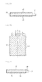
- FIGS. 2A and 2B are respectively a plan view ( 2 A) and a side sectional view ( 2 B) illustrating a cathode including a cathode tab which protrudes from a typical cathode current collector;
- FIGS. 3A and 3B are respectively a plan view ( 3 A) and a side sectional view ( 3 B) illustrating a cathode including an insulation layer on a cathode tab that is composed of a non-coating portion, according to an embodiment of the present invention
- FIGS. 4 to 6 are side sectional views respectively illustrating cathodes including an insulation layer on a cathode tab including a cathode active material coating portion, according to an embodiment of the present invention.
- FIG. 7 is a schematic view illustrating a secondary battery including a cathode tab which includes an insulation layer, according to an embodiment of the present invention.
- a cathode according to an embodiment of the present invention may include a cathode current collector, a cathode tab protruding from the cathode current collector, and an insulation layer coated with an insulating material on the cathode tab.
- the cathode including the insulation layer on the cathode tab may significantly reduce a preparation process of a battery, the cathode may eventually reduce preparation costs of the battery and may further improve the safety of the battery by enlarging an insulation area.
- limitations which may occur when using a typical insulating film or tape, that is, the possibility of exfoliation during the bending of the cathode tab for the attachment to the corresponding portion may be very low and an increase in the thickness of an electrode assembly may not be induced.
- the cathode tab according to an embodiment of the present invention may be formed in a structure in which at least one side of the cathode tab is coated with an electrically insulating material (hereinafter, simply referred to as “insulating material”).
- insulating material an electrically insulating material
- the insulating material may include any one selected from The group consisting of butyl acrylate, styrene, acrylic acid, hydroxyethyl acrylate, and a styrene-butadiene rubber (SBR), or a mixture of two or more thereof.
- the insulating material may be an aqueous solution in which the insulating material is dispersed in an amount of 10 wt % to 90 wt % in water.
- the cathode tab and the cathode current collector are formed. in one piece and the cathode tab may be any one selected from the group consisting of an aluminum foil, an aluminum mesh, or equivalents thereof.
- FIG. 2A and FIG. 2B are respectively examples of a plan view ( 2 A) and a side sectional view ( 2 B) illustrating a cathode including a cathode tab which protrudes from a typical cathode current collector.
- the cathode includes a cathode active material coating portion 10 on one side or both sides of a cathode current collector 30 , and a cathode tab 20 , as a non-coating portion which does not include the cathode active material coating portion, may be formed at one end of the cathode current collector 30 .
- the cathode tab according to an embodiment of the present invention may be formed by notching a continuous cathode sheet, in which the one side or both sides of the cathode current collector are coated with an active material, at a spacing of a unit electrode using dies.
- the cathode tab formed after the notching may be formed as the non-coating portion which does not include the cathode active material coating portion as illustrated in FIGS. 2A, 2B, 3A and 3B , and may include a portion of the cathode active material coating portion as illustrated in FIGS. 4 to 6 .
- the coating portion of the insulation layer according to an embodiment of the present invention may be changed according to various factors such as a structure of the battery. However, the present invention is not limited thereto. Examples of the coating portion will be described with reference to FIGS. 3 to 6 as follows:
- FIGS. 3A and 3B are respectively a plan view ( 3 A) and a side sectional view ( 3 B) illustrating a cathode including a cathode tab that is composed of a non-coating portion, according to an embodiment of the present invention.
- the cathode includes a cathode active material coating portion 10 on one side or both sides of a cathode current collector 30 , and a cathode tab 20 , which is formed at one end of the cathode current collector 30 as a non-coating portion that does not include the cathode active material coating portion, may include an insulation layer 40 coated with an insulating material on one side or both sides thereof.
- the insulation layer 40 may be coated in an amount of 10% to 90% of a total length (d+l) of the cathode tab 20 in a protruding direction L of the cathode tab 20 , and for example, a length l of the insulation layer may be in a range of 1 mm to 10 mm.
- the insulation layer 40 may be coated to have the same width as a width w of the cathode tab 20 which is perpendicular to the protruding direction L of the cathode tab 20 .
- the present invention is not limited thereto.
- the cathode tab 20 may include a portion of a cathode active material coating portion 10 as illustrated in FIGS. 4 to 6 .
- the cathode may include the cathode active material coating portion 10 on one side or both sides of a cathode current collector 30 , and the cathode tab 20 protruding from the current collector 30 may include a portion of the cathode active material coating portion 10 .
- the cathode active material coating portion 10 may include an inclined portion in which the thickness thereof is decreased along a protruding direction of the cathode tab 20 .
- the cathode active material coating portion formed on the cathode tab may further include a flat portion between the cathode current collector and the inclined portion, for example, between the cathode active material coating portion formed on the cathode current collector and the inclined portion.
- an insulation layer 40 may be coated on the cathode tab 20 while including the cathode active material coating portion 10 .
- the cathode active material coating portion 10 formed on the cathode tab 20 may be a portion of the cathode active material coating portion 10 formed on the cathode current collector 30 which extends onto the cathode tab 20 . Therefore, the cathode active material coating portion 10 formed on the cathode tab 20 may have the same material as the cathode active material coating portion 10 formed. on the cathode current collector 30 .
- the insulation layer 40 may include a portion (see FIGS. 4 and 6 ) or all (see FIG. 5 ) of an inclined surface of the inclined portion of the cathode active material, coating portion 10 , and may be formed by being coated in an amount of 10% to 90% of a total length (d+l) of the cathode tab 20 in the protruding direction of the cathode tab 20 .
- a length l of the insulation layer may be in a range of 1 mm to 10 mm, and the insulation layer 40 may be coated to have the same width as a width of the cathode tab 20 which is perpendicular to the protruding direction of the cathode tab 20 .
- the present invention is not limited thereto.
- the insulation layer 40 may be coated in an amount of 10% to 90% of the total length (d+l) of the cathode tab in the protruding direction of the cathode tab from 1 ⁇ 2 of an inclined length S of the inclined portion of the cathode active material coating portion 10 on the cathode tab 20 .
- the insulation layer 40 may be coated in an amount of 10% to 90% of the total length (d+l) of the cathode tab in the protruding direction of the cathode tab while including the entire inclined surface (entire inclined length S) of the inclined portion of the cathode active material coating portion 10 on the cathode tab 20 .
- the insulation layer 40 may be coated to a thickness T of 50% to 100% of a thickness of the cathode active material coating portion 10 on the cathode tab 20 , and for example, the thickness T of the insulation layer 40 may be in a range of 1 ⁇ m to 100 ⁇ m.
- the coating thickness T of the insulation layer is excessively thin, desired electrical insulating properties may be difficult to be obtained.
- the coating thickness T of the insulation layer is excessively thick, it may be undesirable because solidification time of the coating layer may increase or an increase in the thickness of the coating layer may be induced.
- the insulation layer 40 includes a portion of the cathode active material coating portion 10 is for preventing the occurrence of a gap, in which the insulation layer is not formed between the cathode active material coating portion 10 and the cathode tab 20 .
- a coating method of the insulation layer that is formed on the one side or both sides of the cathode tab may also vary.
- the insulation layer may be formed by spray coating an aqueous solution including an insulating material, on the cathode tab.
- the coating of the insulating material on the cathode tab may be performed in any step of the preparation process of the secondary battery.
- the present invention is not limited thereto.
- a cathode current collector For example, one side or both sides of a cathode current collector are coated with a cathode active material, and a non-coating portion of the cathode current collector or a non-coating portion as well as a portion of a cathode active material coating portion is then coated with an insulating material to form an insulation layer. Then, a cathode tab including the insulation layer may be obtained by notching the product thus obtained into a desired shape of the cathode tab using dies.
- a cathode tab is formed by notching a continuous cathode sheet, in which one side or both sides of a cathode current collector are coated with a cathode active material, into a desired shape of the cathode tab at a spacing of a unit electrode using dies, and a cathode tab including an insulation layer may then be obtained by coating the cathode tab thus formed with an insulating material.
- Moisture in the cathode coated with the insulating material may be removed by completely drying the coating layer using a drying method typically known in the art.
- the drying may be performed using a hot air method, a direct heating method, and an induction heating method at a temperature at which moisture is entirely evaporated.
- the present invention is not limited thereto.
- the present invention may provide a secondary battery including the cathode, an anode, and a separator disposed between the cathode and the anode.
- FIG. 7 is a schematic view illustrating a secondary battery according to an embodiment of the present invention.
- the secondary battery according to the embodiment of the present invention may include a cathode 100 including a cathode active material coating portion 10 on a cathode current collector 30 ; an anode 200 including an anode active material coating portion 70 on an anode current collector 60 ; and a separator 300 disposed between the cathode 100 and the anode 200 , wherein a cathode tab 20 including an insulation layer 40 , which is coated with an insulating material, extends in the cathode.
- a cathode active material used may be any one selected from the group consisting of lithium-containing transition metal oxides or equivalents thereof.
- the cathode active material for example, may include a manganese-based spinel active material, lithium metal oxide, or a mixture thereof.
- any one selected from the group consisting of an aluminum foil, an aluminum, mesh, or equivalents thereof may be used as the cathode current collector.
- the present invention is not limited thereto.
- Copper may be used as the anode current collector according to an embodiment of the present invention.
- a carbon-based anode active material such as crystalline carbon, amorphous carbon, or a carbon. composite, may be used alone or in combination of two or more thereof.
- the present invention is not limited thereto.
- Thicknesses of the cathode and the anode may be in a range of about 10 ⁇ m to about 100 ⁇ m, and thicknesses of the active materials coated on the current collectors may be in a range of about 50 ⁇ m to about 200 ⁇ m.
- the present invention is not limited thereto.
- an anode may be prepared to be larger than a cathode in order to prevent a physical short circuit between the cathode and the anode.
- a separator may be inserted between the cathode and the anode in order to prevent a physical short circuit between the cathode and the anode.
- a porous polymer film for example, a porous polymer film prepared from a polyolefin-based polymer, such as an ethylene homopolymer, a propylene homopolymer, an ethylene/butene copolymer, an ethylene/hexene copolymer, and an ethylene/methacrylate copolymer, may be used alone or in a lamination of two or more thereof as the separator.
- a typical porous nonwoven fabric for example, a nonwoven fabric formed of high melting point glass fibers or polyethylene terephthalate fibers may be used.
- the separator is not limited thereto.
- a shape of a battery case accommodating the secondary battery according to the present invention is not particularly limited, and for example, the battery case may be a cylindrical type using a can, a prismatic type, or a pouch type.
- the present invention may be used in a prismatic type battery having significant side effects due to the attachment of an insulating film.
- the cathode tab on which an insulation layer including an insulating material is coated according to an embodiment of present invention, may prevent an internal short circuit which may occur due to cell deformation or sharp edges of electrodes, which are formed during cutting of the electrodes in a preparation process of the battery, when the electrodes are stacked, or may prevent a physical short circuit between the cathode and the anode due to shrinkage of a separator in a high-temperature atmosphere.
- a battery having significantly improved safety and reliability may be prepared, and furthermore, commercialization of the secondary battery may be facilitated.
- the present invention may reduce the possibility a physical short circuit between a cathode and an anode due to cell deformation or shrinkage of a separator in a high-temperature atmosphere. In addition, safety and reliability in battery performance may be significantly improved.
Landscapes
- Chemical & Material Sciences (AREA)
- Chemical Kinetics & Catalysis (AREA)
- Electrochemistry (AREA)
- General Chemical & Material Sciences (AREA)
- Engineering & Computer Science (AREA)
- Manufacturing & Machinery (AREA)
- Materials Engineering (AREA)
- Secondary Cells (AREA)
- Connection Of Batteries Or Terminals (AREA)
- Battery Electrode And Active Subsutance (AREA)
- Cell Electrode Carriers And Collectors (AREA)
- Composite Materials (AREA)
Applications Claiming Priority (3)
| Application Number | Priority Date | Filing Date | Title |
|---|---|---|---|
| KR1020130025785A KR101586530B1 (ko) | 2013-03-11 | 2013-03-11 | 양극 탭 상에 절연층을 포함하는 양극 및 이를 포함하는 이차 전지 |
| KR10-2013-0025785 | 2013-03-11 | ||
| PCT/KR2014/001759 WO2014142458A1 (ko) | 2013-03-11 | 2014-03-04 | 양극 탭 상에 절연층을 포함하는 양극 및 이를 포함하는 이차 전지 |
Related Parent Applications (1)
| Application Number | Title | Priority Date | Filing Date |
|---|---|---|---|
| PCT/KR2014/001759 Continuation WO2014142458A1 (ko) | 2013-03-11 | 2014-03-04 | 양극 탭 상에 절연층을 포함하는 양극 및 이를 포함하는 이차 전지 |
Publications (2)
| Publication Number | Publication Date |
|---|---|
| US20140255778A1 US20140255778A1 (en) | 2014-09-11 |
| US9755213B2 true US9755213B2 (en) | 2017-09-05 |
Family
ID=51537055
Family Applications (1)
| Application Number | Title | Priority Date | Filing Date |
|---|---|---|---|
| US14/283,559 Active US9755213B2 (en) | 2013-03-11 | 2014-05-21 | Cathode including insulation layer on cathode tab and secondary battery including the cathode |
Country Status (8)
| Country | Link |
|---|---|
| US (1) | US9755213B2 (pl) |
| EP (1) | EP2802029B1 (pl) |
| JP (1) | JP6296569B2 (pl) |
| KR (1) | KR101586530B1 (pl) |
| CN (1) | CN104170126A (pl) |
| PL (1) | PL2802029T3 (pl) |
| TW (1) | TWI589055B (pl) |
| WO (1) | WO2014142458A1 (pl) |
Cited By (3)
| Publication number | Priority date | Publication date | Assignee | Title |
|---|---|---|---|---|
| US20230174832A1 (en) * | 2021-12-06 | 2023-06-08 | Aph Epower Co., Ltd. | Current collector protective glue |
| US12040451B2 (en) | 2019-02-01 | 2024-07-16 | Lg Energy Solution, Ltd. | Stack-type electrode assembly comprising electrode with insulation layer and lithium secondary battery comprising the same |
| US12126025B2 (en) | 2019-02-01 | 2024-10-22 | Lg Energy Solution, Ltd. | Electrode with insulation film, manufacturing method thereof, and lithium secondary battery comprising the same |
Families Citing this family (66)
| Publication number | Priority date | Publication date | Assignee | Title |
|---|---|---|---|---|
| CN104885289B (zh) * | 2013-10-29 | 2018-10-09 | 株式会社Lg化学 | 凝胶聚合物电解质和包含其的锂二次电池 |
| EP3073552B1 (en) * | 2014-10-16 | 2021-01-13 | LG Chem, Ltd. | Electrode tab coated with electrical insulating layer and secondary battery comprising same |
| JPWO2016067706A1 (ja) * | 2014-10-27 | 2017-08-31 | Necエナジーデバイス株式会社 | 二次電池用電極の製造方法、二次電池用電極、および二次電池 |
| CN105655540A (zh) * | 2014-11-12 | 2016-06-08 | 宁德时代新能源科技股份有限公司 | 电极极片及锂离子电池 |
| KR102063582B1 (ko) | 2016-08-09 | 2020-01-09 | 주식회사 엘지화학 | 전극 조립체 |
| JP6696692B2 (ja) | 2016-09-20 | 2020-05-20 | 株式会社東芝 | 電極、非水電解質電池、電池パック及び車両 |
| JP6640690B2 (ja) | 2016-09-21 | 2020-02-05 | 株式会社東芝 | 電極構造体、二次電池、電池パック及び車両 |
| JP7002094B2 (ja) * | 2016-10-31 | 2022-01-20 | 株式会社エンビジョンAescジャパン | 電気化学デバイス用の電極と、電気化学デバイスと、それらの製造方法 |
| JP7024723B2 (ja) | 2016-11-04 | 2022-02-24 | 株式会社Gsユアサ | 蓄電素子用電極、蓄電素子、及び蓄電素子用電極の製造方法 |
| US10804571B2 (en) * | 2016-11-24 | 2020-10-13 | Lg Chem, Ltd. | Method of manufacturing battery cell comprising electrode having aperture |
| KR102431281B1 (ko) * | 2017-01-12 | 2022-08-11 | 주식회사 엘지에너지솔루션 | 양극 및 이를 포함하는 이차전지 |
| KR102890540B1 (ko) | 2017-02-22 | 2025-11-26 | 삼성에스디아이 주식회사 | 멀티탭 쇼트 억제 구조를 갖는 이차 전지 |
| JP7060008B2 (ja) * | 2017-03-13 | 2022-04-26 | 株式会社Gsユアサ | 電極及び蓄電素子 |
| US11404682B2 (en) * | 2017-07-05 | 2022-08-02 | Apple Inc. | Non-rectangular shaped electrodes utilizing complex shaped insulation |
| KR102529492B1 (ko) * | 2017-11-17 | 2023-05-04 | 현대자동차주식회사 | 전고체 전지의 제조 방법 및 이에 의해 제조된 전고체 전지 |
| WO2019135640A1 (ko) | 2018-01-04 | 2019-07-11 | 주식회사 엘지화학 | 절연 코팅층이 구비된 전극탭을 포함하는 이차전지 |
| US12057566B2 (en) * | 2018-02-01 | 2024-08-06 | Lg Energy Solution, Ltd. | Electrode for lithium secondary battery, method of preparing the same and lithium secondary battery including the same |
| CN111937218B (zh) * | 2018-04-06 | 2024-08-09 | 松下新能源株式会社 | 非水电解质二次电池 |
| CN111883740B (zh) * | 2018-06-22 | 2021-09-21 | 宁德时代新能源科技股份有限公司 | 一种极片及二次电池 |
| CN109449478A (zh) | 2018-11-05 | 2019-03-08 | 宁德新能源科技有限公司 | 电化学装置 |
| US10511059B1 (en) * | 2018-11-15 | 2019-12-17 | ZAF Energy Systems, Incorporated | Alkaline pouch cell with coated terminals |
| JP6983147B2 (ja) * | 2018-12-26 | 2021-12-17 | 本田技研工業株式会社 | 固体電池用電極および固体電池 |
| CN116093337A (zh) * | 2019-03-29 | 2023-05-09 | 宁德新能源科技有限公司 | 电池 |
| JP7425586B2 (ja) * | 2019-12-03 | 2024-01-31 | 株式会社Aescジャパン | 正極電極、リチウムイオン二次電池及び正極電極シートの製造方法 |
| KR102839855B1 (ko) * | 2019-12-12 | 2025-07-29 | 주식회사 엘지에너지솔루션 | 전극조립체 및 이차전지 및 그의 제조방법 |
| WO2021125337A1 (ja) * | 2019-12-19 | 2021-06-24 | 株式会社村田製作所 | 固体電池 |
| JP7264077B2 (ja) * | 2020-01-31 | 2023-04-25 | トヨタ自動車株式会社 | 全固体電池 |
| KR102917236B1 (ko) | 2020-02-27 | 2026-01-22 | 주식회사 엘지에너지솔루션 | 탭 상에 형성된 절연필름을 포함하는 전극 조립체, 이의 제조방법, 및 이를 포함하는 리튬 이차전지 |
| KR102852580B1 (ko) * | 2020-04-16 | 2025-08-28 | 주식회사 엘지에너지솔루션 | 이차 전지용 전극 |
| CN111554877A (zh) * | 2020-06-10 | 2020-08-18 | 湖北亿纬动力有限公司 | 一种正极片及其制备方法、电芯和锂离子电池 |
| CN214313441U (zh) * | 2020-08-19 | 2021-09-28 | 广东微电新能源有限公司 | 储能装置的电芯以及储能装置 |
| JP7385816B2 (ja) | 2020-09-16 | 2023-11-24 | トヨタ自動車株式会社 | 非水電解液二次電池 |
| CN118738778A (zh) | 2020-09-30 | 2024-10-01 | 宁德时代新能源科技股份有限公司 | 圆柱型电池单体、电池、用电装置、制造方法及制造系统 |
| KR102834995B1 (ko) * | 2020-10-29 | 2025-07-16 | 에스케이온 주식회사 | 이차전지용 양극 및 그 제조방법 |
| CN114447282A (zh) * | 2020-10-30 | 2022-05-06 | 北京小米移动软件有限公司 | 极片及其加工方法、锂电池 |
| KR102824735B1 (ko) | 2020-11-02 | 2025-06-24 | 주식회사 엘지에너지솔루션 | 전극리드와 전극탭의 용접성이 우수한 전극 및 이의 제조방법 |
| CN112886066B (zh) * | 2021-01-13 | 2023-02-17 | 上海瑞浦青创新能源有限公司 | 锂离子电池及提高锂离子电池安全性能的防护方法 |
| DE102021106975A1 (de) | 2021-03-22 | 2022-09-22 | Volkswagen Aktiengesellschaft | Batteriezelle |
| CN113193204B (zh) * | 2021-04-27 | 2023-03-07 | 孚能科技(赣州)股份有限公司 | 电极片及其制备方法、电芯结构、电池装置 |
| CN115528201A (zh) * | 2021-06-24 | 2022-12-27 | 宁德时代新能源科技股份有限公司 | 电极组件、电池、电池模块、电池包以及用电装置 |
| CN115555852B (zh) | 2021-06-30 | 2023-06-30 | 宁德时代新能源科技股份有限公司 | 极片成型方法及设备 |
| KR20230012439A (ko) | 2021-07-15 | 2023-01-26 | 주식회사 엘지에너지솔루션 | 전극 |
| US20240145722A1 (en) | 2021-07-15 | 2024-05-02 | Lg Energy Solution, Ltd. | Electrode |
| KR20230061488A (ko) * | 2021-07-30 | 2023-05-08 | 컨템포러리 엠퍼렉스 테크놀로지 씨오., 리미티드 | 배터리 극판, 전극 어셈블리, 배터리 셀, 배터리 및 전기 장치 |
| US20250219272A1 (en) * | 2021-08-05 | 2025-07-03 | Lg Energy Solution, Ltd. | Electrode assembly, battery, and battery pack and vehicle including the same |
| KR102901452B1 (ko) * | 2021-08-19 | 2025-12-18 | 주식회사 엘지에너지솔루션 | 단락 방지용 코팅부가 구비된 전극조립체 |
| CN216015476U (zh) * | 2021-09-30 | 2022-03-11 | 宁德时代新能源科技股份有限公司 | 电池单体及与其相关的电池、用电装置和制备装置 |
| KR102951733B1 (ko) * | 2021-10-13 | 2026-04-14 | 주식회사 엘지에너지솔루션 | 접착코팅부가 부가된 리튬 이차전지용 전극 및 이의 제조방법 |
| US20230117276A1 (en) * | 2021-10-14 | 2023-04-20 | Lg Energy Solution, Ltd. | Lithium secondary battery |
| KR102696063B1 (ko) | 2021-11-01 | 2024-08-19 | 주식회사 엘지에너지솔루션 | 전극 절연 코팅용 조성물 및 이를 이용한 전극 |
| CN219017720U (zh) * | 2021-11-30 | 2023-05-12 | 株式会社Lg新能源 | 电极组件、电池单元 |
| KR102945058B1 (ko) * | 2021-12-03 | 2026-03-26 | 주식회사 엘지에너지솔루션 | 절연 코팅층이 형성된 양극을 포함하는 전극조립체 |
| KR102922136B1 (ko) * | 2021-12-07 | 2026-02-03 | 주식회사 엘지에너지솔루션 | 비정형의 스티커 타입의 보호 테이프가 형성된 전지셀 |
| KR20230085534A (ko) * | 2021-12-07 | 2023-06-14 | 주식회사 엘지에너지솔루션 | 모따기 된 보호 테이프가 형성된 전지셀 |
| EP4293814A4 (en) * | 2021-12-07 | 2025-03-19 | LG Energy Solution Ltd. | BATTERY CELL WITH ATYPICAL STICKER TYPE PROTECTIVE STRIP |
| CA3243080A1 (en) * | 2022-01-19 | 2025-04-09 | Lg Energy Solution, Ltd. | Electrode assembly with a short-circuit prevention structure |
| KR102716579B1 (ko) | 2022-04-04 | 2024-10-15 | 주식회사 엘지화학 | 리튬이차전지용 양극 바인더 또는 양극 절연액의 제조방법 및 이에 따라 제조한 양극 바인더 또는 양극 절연액을 포함하는 리튬이차전지 |
| EP4372867A4 (en) | 2022-04-04 | 2025-12-03 | Lg Chemical Ltd | INSULATING LAYER COMPOSITION FOR LITHIUM SECONDARY BATTERY AND LITHIUM SECONDARY BATTERY INCLUDING IT |
| CN118077084A (zh) | 2022-04-04 | 2024-05-24 | 株式会社Lg化学 | 用于锂二次电池的绝缘层组合物和包含其的锂二次电池 |
| JP2024539673A (ja) * | 2022-04-04 | 2024-10-29 | エルジー・ケム・リミテッド | リチウム二次電池用絶縁層組成物およびそれを含むリチウム二次電池 |
| KR20240005450A (ko) * | 2022-07-05 | 2024-01-12 | 주식회사 엘지에너지솔루션 | 전극 조립체, 전극 조립체 제조방법, 이차 전지, 배터리 팩 및 자동차 |
| KR102922988B1 (ko) * | 2022-07-08 | 2026-02-03 | 삼성에스디아이 주식회사 | 리튬 이차 전지용 전극, 이를 포함하는 전극 조립체 및 리튬 이차 전지 |
| EP4333089A1 (en) * | 2022-09-05 | 2024-03-06 | LG Energy Solution, Ltd. | Battery manufacturing method and system |
| US20240097266A1 (en) * | 2022-09-15 | 2024-03-21 | GM Global Technology Operations LLC | Battery assembly and method therefor |
| JP2025531594A (ja) * | 2022-09-19 | 2025-09-22 | 珠海冠宇電池股分有限公司 | 電池極板、セルおよび電池 |
| KR20260019131A (ko) * | 2024-08-01 | 2026-02-10 | 삼성에스디아이 주식회사 | 전극, 이차전지 및 전극 제조장치 |
Citations (10)
| Publication number | Priority date | Publication date | Assignee | Title |
|---|---|---|---|---|
| JP2004158434A (ja) | 2002-10-15 | 2004-06-03 | Dainippon Printing Co Ltd | リチウム電池 |
| US20040202928A1 (en) * | 2003-01-26 | 2004-10-14 | Sanyo Electric Co., Ltd. | Non-aqueous electrolyte secondary battery and manufacturing methods of an electrode used therein |
| JP2005166581A (ja) | 2003-12-05 | 2005-06-23 | Nissan Motor Co Ltd | 二次電池、及び、該二次電池を用いた組電池の充放電制御方法 |
| US20090111011A1 (en) * | 2007-10-30 | 2009-04-30 | Samsung Sdi Co., Ltd. | Electrode assembly and secondary battery having the same |
| JP2009181899A (ja) | 2008-01-31 | 2009-08-13 | Sanyo Electric Co Ltd | 積層式電池 |
| US20100248026A1 (en) * | 2009-03-25 | 2010-09-30 | Tdk Corporation | Electrode for lithium ion secondary battery and lithium ion secondary battery |
| JP2011081992A (ja) | 2009-10-06 | 2011-04-21 | Sumitomo Electric Ind Ltd | リード部材の製造方法 |
| JP2011216403A (ja) | 2010-04-01 | 2011-10-27 | Hitachi Vehicle Energy Ltd | 角形リチウムイオン二次電池 |
| US20120082891A1 (en) | 2010-10-01 | 2012-04-05 | Samsung Sdi Co., Ltd. | Secondary battery |
| EP2450989A2 (en) * | 2010-11-05 | 2012-05-09 | GS Yuasa International Ltd. | Electrode for electricity-storing device, electricity-storing device employing such electrode, and method of manufacturing electrode for electricity-storing device |
Family Cites Families (1)
| Publication number | Priority date | Publication date | Assignee | Title |
|---|---|---|---|---|
| CN101604737B (zh) * | 2008-06-13 | 2014-03-12 | 深圳市比克电池有限公司 | 一种二次电池 |
-
2013
- 2013-03-11 KR KR1020130025785A patent/KR101586530B1/ko active Active
-
2014
- 2014-03-04 PL PL14741496T patent/PL2802029T3/pl unknown
- 2014-03-04 CN CN201480000768.7A patent/CN104170126A/zh active Pending
- 2014-03-04 EP EP14741496.5A patent/EP2802029B1/en active Active
- 2014-03-04 JP JP2015505669A patent/JP6296569B2/ja active Active
- 2014-03-04 WO PCT/KR2014/001759 patent/WO2014142458A1/ko not_active Ceased
- 2014-03-11 TW TW103108447A patent/TWI589055B/zh active
- 2014-05-21 US US14/283,559 patent/US9755213B2/en active Active
Patent Citations (10)
| Publication number | Priority date | Publication date | Assignee | Title |
|---|---|---|---|---|
| JP2004158434A (ja) | 2002-10-15 | 2004-06-03 | Dainippon Printing Co Ltd | リチウム電池 |
| US20040202928A1 (en) * | 2003-01-26 | 2004-10-14 | Sanyo Electric Co., Ltd. | Non-aqueous electrolyte secondary battery and manufacturing methods of an electrode used therein |
| JP2005166581A (ja) | 2003-12-05 | 2005-06-23 | Nissan Motor Co Ltd | 二次電池、及び、該二次電池を用いた組電池の充放電制御方法 |
| US20090111011A1 (en) * | 2007-10-30 | 2009-04-30 | Samsung Sdi Co., Ltd. | Electrode assembly and secondary battery having the same |
| JP2009181899A (ja) | 2008-01-31 | 2009-08-13 | Sanyo Electric Co Ltd | 積層式電池 |
| US20100248026A1 (en) * | 2009-03-25 | 2010-09-30 | Tdk Corporation | Electrode for lithium ion secondary battery and lithium ion secondary battery |
| JP2011081992A (ja) | 2009-10-06 | 2011-04-21 | Sumitomo Electric Ind Ltd | リード部材の製造方法 |
| JP2011216403A (ja) | 2010-04-01 | 2011-10-27 | Hitachi Vehicle Energy Ltd | 角形リチウムイオン二次電池 |
| US20120082891A1 (en) | 2010-10-01 | 2012-04-05 | Samsung Sdi Co., Ltd. | Secondary battery |
| EP2450989A2 (en) * | 2010-11-05 | 2012-05-09 | GS Yuasa International Ltd. | Electrode for electricity-storing device, electricity-storing device employing such electrode, and method of manufacturing electrode for electricity-storing device |
Non-Patent Citations (3)
| Title |
|---|
| European Office Action dated Mar. 20, 2017 in European Application No. 14741496.5. |
| Extended European Search Report, dated Jan. 26, 2015, issued in European Application No. 14741496.5. |
| International Search Report, dated Jun. 12, 2014, for International Application No. PCT/KR2014/001759. |
Cited By (3)
| Publication number | Priority date | Publication date | Assignee | Title |
|---|---|---|---|---|
| US12040451B2 (en) | 2019-02-01 | 2024-07-16 | Lg Energy Solution, Ltd. | Stack-type electrode assembly comprising electrode with insulation layer and lithium secondary battery comprising the same |
| US12126025B2 (en) | 2019-02-01 | 2024-10-22 | Lg Energy Solution, Ltd. | Electrode with insulation film, manufacturing method thereof, and lithium secondary battery comprising the same |
| US20230174832A1 (en) * | 2021-12-06 | 2023-06-08 | Aph Epower Co., Ltd. | Current collector protective glue |
Also Published As
| Publication number | Publication date |
|---|---|
| CN104170126A (zh) | 2014-11-26 |
| JP6296569B2 (ja) | 2018-03-20 |
| KR101586530B1 (ko) | 2016-01-21 |
| US20140255778A1 (en) | 2014-09-11 |
| WO2014142458A1 (ko) | 2014-09-18 |
| KR20140112609A (ko) | 2014-09-24 |
| TW201508985A (zh) | 2015-03-01 |
| JP2015517189A (ja) | 2015-06-18 |
| PL2802029T3 (pl) | 2019-02-28 |
| EP2802029A4 (en) | 2015-02-25 |
| EP2802029A1 (en) | 2014-11-12 |
| EP2802029B1 (en) | 2018-09-12 |
| TWI589055B (zh) | 2017-06-21 |
Similar Documents
| Publication | Publication Date | Title |
|---|---|---|
| EP2802029B1 (en) | Cathode including insulating layer on cathode tab and secondary battery including cathode | |
| KR102160701B1 (ko) | 천공 구조의 집전체를 포함하는 전극, 이를 포함하는 리튬 이차전지 | |
| CN100440588C (zh) | 锂离子二次电池 | |
| EP3179544B1 (en) | Secondary battery including high-capacity negative electrode and manufacturing method the same | |
| KR102145534B1 (ko) | 점착력이 상이한 점착 코팅부들을 포함하는 분리막 및 이를 포함하는 전극조립체 | |
| JP5499758B2 (ja) | 非水電解質二次電池及びその製造方法 | |
| KR101590217B1 (ko) | 전극조립체의 제조 방법 및 이를 이용하여 제조된 전극조립체 | |
| KR101471795B1 (ko) | 비수 전해액 리튬 2차 전지 | |
| EP3276709B1 (en) | Negative electrode comprising mesh-type current collector, lithium secondary battery comprising the same, and manufacturing method thereof | |
| KR102484265B1 (ko) | 전극 조립체 및 이를 이용한 이차 전지 | |
| KR102417105B1 (ko) | 개선된 전극 탭과 집전체 연결 구조를 갖는 전극 조립체 및 그 제조 방법 | |
| US8715848B2 (en) | Lithium ion secondary battery with insulating member having a broken hollow portion and method for producing the same | |
| JP6936670B2 (ja) | リチウムイオン電池用セパレータ | |
| CN109565069B (zh) | 电极组件及其制造方法 | |
| KR20150051046A (ko) | 전극의 표면에 패턴을 형성하는 방법, 이 방법을 이용해 제조된 전극 및 이 전극을 포함하는 이차전지 | |
| CN207504104U (zh) | 一种集流体及使用该集流体的二次电池 | |
| JP5945401B2 (ja) | リチウムイオン二次電池の正極集電体用箔の製造方法 | |
| KR102148506B1 (ko) | 메쉬 형태의 집전체를 포함하는 음극, 이를 포함하는 리튬 이차전지 및 이의 제조방법 | |
| CN114530670B (zh) | 一种电芯结构以及二次电池 | |
| JP7736541B2 (ja) | 二次電池の製造方法 | |
| CN111066175A (zh) | 非水电解液二次电池 | |
| KR102726786B1 (ko) | 단락 방지를 위한 절연부재를 구비한 전고체 전지 및 이의 제조방법 | |
| KR101519074B1 (ko) | 전극조립체의 제조방법 | |
| KR101586268B1 (ko) | 이차 전지용 음극 활물질의 제조방법 | |
| KR20250084884A (ko) | 원통형 리튬 이차 전지 |
Legal Events
| Date | Code | Title | Description |
|---|---|---|---|
| AS | Assignment |
Owner name: LG CHEM, LTD., KOREA, REPUBLIC OF Free format text: ASSIGNMENT OF ASSIGNORS INTEREST;ASSIGNORS:HUH, JUN WOO;KIM, HYUK SU;KU, DAE GEUN;AND OTHERS;REEL/FRAME:033029/0117 Effective date: 20140528 |
|
| STCF | Information on status: patent grant |
Free format text: PATENTED CASE |
|
| MAFP | Maintenance fee payment |
Free format text: PAYMENT OF MAINTENANCE FEE, 4TH YEAR, LARGE ENTITY (ORIGINAL EVENT CODE: M1551); ENTITY STATUS OF PATENT OWNER: LARGE ENTITY Year of fee payment: 4 |
|
| AS | Assignment |
Owner name: LG ENERGY SOLUTION, LTD., KOREA, REPUBLIC OF Free format text: ASSIGNMENT OF ASSIGNORS INTEREST;ASSIGNOR:LG CHEM, LTD.;REEL/FRAME:058295/0068 Effective date: 20211027 |
|
| MAFP | Maintenance fee payment |
Free format text: PAYMENT OF MAINTENANCE FEE, 8TH YEAR, LARGE ENTITY (ORIGINAL EVENT CODE: M1552); ENTITY STATUS OF PATENT OWNER: LARGE ENTITY Year of fee payment: 8 |