US9718371B2 - Recharging of battery electric vehicles on a smart electrical grid system - Google Patents
Recharging of battery electric vehicles on a smart electrical grid system Download PDFInfo
- Publication number
- US9718371B2 US9718371B2 US13/174,227 US201113174227A US9718371B2 US 9718371 B2 US9718371 B2 US 9718371B2 US 201113174227 A US201113174227 A US 201113174227A US 9718371 B2 US9718371 B2 US 9718371B2
- Authority
- US
- United States
- Prior art keywords
- battery electric
- recharging
- electric vehicle
- control module
- stations
- Prior art date
- Legal status (The legal status is an assumption and is not a legal conclusion. Google has not performed a legal analysis and makes no representation as to the accuracy of the status listed.)
- Active, expires
Links
- 230000003466 anti-cipated effect Effects 0.000 claims abstract description 36
- 238000004590 computer program Methods 0.000 claims abstract description 19
- 238000004891 communication Methods 0.000 claims description 28
- 238000003860 storage Methods 0.000 claims description 12
- 230000007613 environmental effect Effects 0.000 claims description 6
- 238000009826 distribution Methods 0.000 claims description 4
- 230000004044 response Effects 0.000 claims description 3
- 238000000034 method Methods 0.000 description 9
- 238000010586 diagram Methods 0.000 description 8
- 238000012545 processing Methods 0.000 description 6
- 230000006870 function Effects 0.000 description 4
- 230000003287 optical effect Effects 0.000 description 4
- 230000011218 segmentation Effects 0.000 description 4
- 238000007792 addition Methods 0.000 description 2
- 230000005540 biological transmission Effects 0.000 description 2
- 238000012986 modification Methods 0.000 description 2
- 230000004048 modification Effects 0.000 description 2
- 239000013307 optical fiber Substances 0.000 description 2
- 230000002093 peripheral effect Effects 0.000 description 2
- 230000008569 process Effects 0.000 description 2
- 230000000644 propagated effect Effects 0.000 description 2
- 229930091051 Arenine Natural products 0.000 description 1
- 238000013459 approach Methods 0.000 description 1
- 239000003990 capacitor Substances 0.000 description 1
- 238000002485 combustion reaction Methods 0.000 description 1
- 230000003247 decreasing effect Effects 0.000 description 1
- 230000005611 electricity Effects 0.000 description 1
- RGNPBRKPHBKNKX-UHFFFAOYSA-N hexaflumuron Chemical compound C1=C(Cl)C(OC(F)(F)C(F)F)=C(Cl)C=C1NC(=O)NC(=O)C1=C(F)C=CC=C1F RGNPBRKPHBKNKX-UHFFFAOYSA-N 0.000 description 1
- 229930195733 hydrocarbon Natural products 0.000 description 1
- 150000002430 hydrocarbons Chemical class 0.000 description 1
- 230000006698 induction Effects 0.000 description 1
- 230000003993 interaction Effects 0.000 description 1
- 238000004519 manufacturing process Methods 0.000 description 1
- 230000007246 mechanism Effects 0.000 description 1
- 239000004065 semiconductor Substances 0.000 description 1
Images


Classifications
-
- B60L11/1837—
-
- H—ELECTRICITY
- H02—GENERATION; CONVERSION OR DISTRIBUTION OF ELECTRIC POWER
- H02J—CIRCUIT ARRANGEMENTS OR SYSTEMS FOR SUPPLYING OR DISTRIBUTING ELECTRIC POWER; SYSTEMS FOR STORING ELECTRIC ENERGY
- H02J13/00—Circuit arrangements for providing remote indication of network conditions, e.g. an instantaneous record of the open or closed condition of each circuitbreaker in the network; Circuit arrangements for providing remote control of switching means in a power distribution network, e.g. switching in and out of current consumers by using a pulse code signal carried by the network
- H02J13/00006—Circuit arrangements for providing remote indication of network conditions, e.g. an instantaneous record of the open or closed condition of each circuitbreaker in the network; Circuit arrangements for providing remote control of switching means in a power distribution network, e.g. switching in and out of current consumers by using a pulse code signal carried by the network characterised by information or instructions transport means between the monitoring, controlling or managing units and monitored, controlled or operated power network element or electrical equipment
- H02J13/00016—Circuit arrangements for providing remote indication of network conditions, e.g. an instantaneous record of the open or closed condition of each circuitbreaker in the network; Circuit arrangements for providing remote control of switching means in a power distribution network, e.g. switching in and out of current consumers by using a pulse code signal carried by the network characterised by information or instructions transport means between the monitoring, controlling or managing units and monitored, controlled or operated power network element or electrical equipment using a wired telecommunication network or a data transmission bus
-
- B60L11/1842—
-
- B60L11/1844—
-
- B60L11/1861—
-
- B—PERFORMING OPERATIONS; TRANSPORTING
- B60—VEHICLES IN GENERAL
- B60L—PROPULSION OF ELECTRICALLY-PROPELLED VEHICLES; SUPPLYING ELECTRIC POWER FOR AUXILIARY EQUIPMENT OF ELECTRICALLY-PROPELLED VEHICLES; ELECTRODYNAMIC BRAKE SYSTEMS FOR VEHICLES IN GENERAL; MAGNETIC SUSPENSION OR LEVITATION FOR VEHICLES; MONITORING OPERATING VARIABLES OF ELECTRICALLY-PROPELLED VEHICLES; ELECTRIC SAFETY DEVICES FOR ELECTRICALLY-PROPELLED VEHICLES
- B60L53/00—Methods of charging batteries, specially adapted for electric vehicles; Charging stations or on-board charging equipment therefor; Exchange of energy storage elements in electric vehicles
- B60L53/30—Constructional details of charging stations
- B60L53/32—Constructional details of charging stations by charging in short intervals along the itinerary, e.g. during short stops
-
- B—PERFORMING OPERATIONS; TRANSPORTING
- B60—VEHICLES IN GENERAL
- B60L—PROPULSION OF ELECTRICALLY-PROPELLED VEHICLES; SUPPLYING ELECTRIC POWER FOR AUXILIARY EQUIPMENT OF ELECTRICALLY-PROPELLED VEHICLES; ELECTRODYNAMIC BRAKE SYSTEMS FOR VEHICLES IN GENERAL; MAGNETIC SUSPENSION OR LEVITATION FOR VEHICLES; MONITORING OPERATING VARIABLES OF ELECTRICALLY-PROPELLED VEHICLES; ELECTRIC SAFETY DEVICES FOR ELECTRICALLY-PROPELLED VEHICLES
- B60L53/00—Methods of charging batteries, specially adapted for electric vehicles; Charging stations or on-board charging equipment therefor; Exchange of energy storage elements in electric vehicles
- B60L53/60—Monitoring or controlling charging stations
- B60L53/63—Monitoring or controlling charging stations in response to network capacity
-
- B—PERFORMING OPERATIONS; TRANSPORTING
- B60—VEHICLES IN GENERAL
- B60L—PROPULSION OF ELECTRICALLY-PROPELLED VEHICLES; SUPPLYING ELECTRIC POWER FOR AUXILIARY EQUIPMENT OF ELECTRICALLY-PROPELLED VEHICLES; ELECTRODYNAMIC BRAKE SYSTEMS FOR VEHICLES IN GENERAL; MAGNETIC SUSPENSION OR LEVITATION FOR VEHICLES; MONITORING OPERATING VARIABLES OF ELECTRICALLY-PROPELLED VEHICLES; ELECTRIC SAFETY DEVICES FOR ELECTRICALLY-PROPELLED VEHICLES
- B60L55/00—Arrangements for supplying energy stored within a vehicle to a power network, i.e. vehicle-to-grid [V2G] arrangements
-
- B—PERFORMING OPERATIONS; TRANSPORTING
- B60—VEHICLES IN GENERAL
- B60L—PROPULSION OF ELECTRICALLY-PROPELLED VEHICLES; SUPPLYING ELECTRIC POWER FOR AUXILIARY EQUIPMENT OF ELECTRICALLY-PROPELLED VEHICLES; ELECTRODYNAMIC BRAKE SYSTEMS FOR VEHICLES IN GENERAL; MAGNETIC SUSPENSION OR LEVITATION FOR VEHICLES; MONITORING OPERATING VARIABLES OF ELECTRICALLY-PROPELLED VEHICLES; ELECTRIC SAFETY DEVICES FOR ELECTRICALLY-PROPELLED VEHICLES
- B60L58/00—Methods or circuit arrangements for monitoring or controlling batteries or fuel cells, specially adapted for electric vehicles
- B60L58/10—Methods or circuit arrangements for monitoring or controlling batteries or fuel cells, specially adapted for electric vehicles for monitoring or controlling batteries
- B60L58/12—Methods or circuit arrangements for monitoring or controlling batteries or fuel cells, specially adapted for electric vehicles for monitoring or controlling batteries responding to state of charge [SoC]
-
- G—PHYSICS
- G05—CONTROLLING; REGULATING
- G05B—CONTROL OR REGULATING SYSTEMS IN GENERAL; FUNCTIONAL ELEMENTS OF SUCH SYSTEMS; MONITORING OR TESTING ARRANGEMENTS FOR SUCH SYSTEMS OR ELEMENTS
- G05B15/00—Systems controlled by a computer
- G05B15/02—Systems controlled by a computer electric
-
- G—PHYSICS
- G05—CONTROLLING; REGULATING
- G05F—SYSTEMS FOR REGULATING ELECTRIC OR MAGNETIC VARIABLES
- G05F5/00—Systems for regulating electric variables by detecting deviations in the electric input to the system and thereby controlling a device within the system to obtain a regulated output
-
- G—PHYSICS
- G06—COMPUTING; CALCULATING OR COUNTING
- G06Q—INFORMATION AND COMMUNICATION TECHNOLOGY [ICT] SPECIALLY ADAPTED FOR ADMINISTRATIVE, COMMERCIAL, FINANCIAL, MANAGERIAL OR SUPERVISORY PURPOSES; SYSTEMS OR METHODS SPECIALLY ADAPTED FOR ADMINISTRATIVE, COMMERCIAL, FINANCIAL, MANAGERIAL OR SUPERVISORY PURPOSES, NOT OTHERWISE PROVIDED FOR
- G06Q10/00—Administration; Management
- G06Q10/02—Reservations, e.g. for tickets, services or events
-
- G—PHYSICS
- G06—COMPUTING; CALCULATING OR COUNTING
- G06Q—INFORMATION AND COMMUNICATION TECHNOLOGY [ICT] SPECIALLY ADAPTED FOR ADMINISTRATIVE, COMMERCIAL, FINANCIAL, MANAGERIAL OR SUPERVISORY PURPOSES; SYSTEMS OR METHODS SPECIALLY ADAPTED FOR ADMINISTRATIVE, COMMERCIAL, FINANCIAL, MANAGERIAL OR SUPERVISORY PURPOSES, NOT OTHERWISE PROVIDED FOR
- G06Q10/00—Administration; Management
- G06Q10/06—Resources, workflows, human or project management; Enterprise or organisation planning; Enterprise or organisation modelling
- G06Q10/063—Operations research, analysis or management
- G06Q10/0631—Resource planning, allocation, distributing or scheduling for enterprises or organisations
-
- G—PHYSICS
- G06—COMPUTING; CALCULATING OR COUNTING
- G06Q—INFORMATION AND COMMUNICATION TECHNOLOGY [ICT] SPECIALLY ADAPTED FOR ADMINISTRATIVE, COMMERCIAL, FINANCIAL, MANAGERIAL OR SUPERVISORY PURPOSES; SYSTEMS OR METHODS SPECIALLY ADAPTED FOR ADMINISTRATIVE, COMMERCIAL, FINANCIAL, MANAGERIAL OR SUPERVISORY PURPOSES, NOT OTHERWISE PROVIDED FOR
- G06Q50/00—Information and communication technology [ICT] specially adapted for implementation of business processes of specific business sectors, e.g. utilities or tourism
- G06Q50/06—Energy or water supply
-
- H02J13/0062—
-
- H02J3/005—
-
- H—ELECTRICITY
- H02—GENERATION; CONVERSION OR DISTRIBUTION OF ELECTRIC POWER
- H02J—CIRCUIT ARRANGEMENTS OR SYSTEMS FOR SUPPLYING OR DISTRIBUTING ELECTRIC POWER; SYSTEMS FOR STORING ELECTRIC ENERGY
- H02J3/00—Circuit arrangements for ac mains or ac distribution networks
- H02J3/007—Arrangements for selectively connecting the load or loads to one or several among a plurality of power lines or power sources
- H02J3/0075—Arrangements for selectively connecting the load or loads to one or several among a plurality of power lines or power sources for providing alternative feeding paths between load and source according to economic or energy efficiency considerations, e.g. economic dispatch
-
- H—ELECTRICITY
- H02—GENERATION; CONVERSION OR DISTRIBUTION OF ELECTRIC POWER
- H02J—CIRCUIT ARRANGEMENTS OR SYSTEMS FOR SUPPLYING OR DISTRIBUTING ELECTRIC POWER; SYSTEMS FOR STORING ELECTRIC ENERGY
- H02J7/00—Circuit arrangements for charging or depolarising batteries or for supplying loads from batteries
- H02J7/0013—Circuit arrangements for charging or depolarising batteries or for supplying loads from batteries acting upon several batteries simultaneously or sequentially
-
- H02J7/0027—
-
- B—PERFORMING OPERATIONS; TRANSPORTING
- B60—VEHICLES IN GENERAL
- B60L—PROPULSION OF ELECTRICALLY-PROPELLED VEHICLES; SUPPLYING ELECTRIC POWER FOR AUXILIARY EQUIPMENT OF ELECTRICALLY-PROPELLED VEHICLES; ELECTRODYNAMIC BRAKE SYSTEMS FOR VEHICLES IN GENERAL; MAGNETIC SUSPENSION OR LEVITATION FOR VEHICLES; MONITORING OPERATING VARIABLES OF ELECTRICALLY-PROPELLED VEHICLES; ELECTRIC SAFETY DEVICES FOR ELECTRICALLY-PROPELLED VEHICLES
- B60L2200/00—Type of vehicles
- B60L2200/26—Rail vehicles
-
- B—PERFORMING OPERATIONS; TRANSPORTING
- B60—VEHICLES IN GENERAL
- B60L—PROPULSION OF ELECTRICALLY-PROPELLED VEHICLES; SUPPLYING ELECTRIC POWER FOR AUXILIARY EQUIPMENT OF ELECTRICALLY-PROPELLED VEHICLES; ELECTRODYNAMIC BRAKE SYSTEMS FOR VEHICLES IN GENERAL; MAGNETIC SUSPENSION OR LEVITATION FOR VEHICLES; MONITORING OPERATING VARIABLES OF ELECTRICALLY-PROPELLED VEHICLES; ELECTRIC SAFETY DEVICES FOR ELECTRICALLY-PROPELLED VEHICLES
- B60L2240/00—Control parameters of input or output; Target parameters
- B60L2240/60—Navigation input
- B60L2240/62—Vehicle position
-
- B—PERFORMING OPERATIONS; TRANSPORTING
- B60—VEHICLES IN GENERAL
- B60L—PROPULSION OF ELECTRICALLY-PROPELLED VEHICLES; SUPPLYING ELECTRIC POWER FOR AUXILIARY EQUIPMENT OF ELECTRICALLY-PROPELLED VEHICLES; ELECTRODYNAMIC BRAKE SYSTEMS FOR VEHICLES IN GENERAL; MAGNETIC SUSPENSION OR LEVITATION FOR VEHICLES; MONITORING OPERATING VARIABLES OF ELECTRICALLY-PROPELLED VEHICLES; ELECTRIC SAFETY DEVICES FOR ELECTRICALLY-PROPELLED VEHICLES
- B60L2260/00—Operating Modes
- B60L2260/40—Control modes
- B60L2260/50—Control modes by future state prediction
- B60L2260/54—Energy consumption estimation
-
- H—ELECTRICITY
- H02—GENERATION; CONVERSION OR DISTRIBUTION OF ELECTRIC POWER
- H02J—CIRCUIT ARRANGEMENTS OR SYSTEMS FOR SUPPLYING OR DISTRIBUTING ELECTRIC POWER; SYSTEMS FOR STORING ELECTRIC ENERGY
- H02J13/00—Circuit arrangements for providing remote indication of network conditions, e.g. an instantaneous record of the open or closed condition of each circuitbreaker in the network; Circuit arrangements for providing remote control of switching means in a power distribution network, e.g. switching in and out of current consumers by using a pulse code signal carried by the network
- H02J13/00006—Circuit arrangements for providing remote indication of network conditions, e.g. an instantaneous record of the open or closed condition of each circuitbreaker in the network; Circuit arrangements for providing remote control of switching means in a power distribution network, e.g. switching in and out of current consumers by using a pulse code signal carried by the network characterised by information or instructions transport means between the monitoring, controlling or managing units and monitored, controlled or operated power network element or electrical equipment
- H02J13/00016—Circuit arrangements for providing remote indication of network conditions, e.g. an instantaneous record of the open or closed condition of each circuitbreaker in the network; Circuit arrangements for providing remote control of switching means in a power distribution network, e.g. switching in and out of current consumers by using a pulse code signal carried by the network characterised by information or instructions transport means between the monitoring, controlling or managing units and monitored, controlled or operated power network element or electrical equipment using a wired telecommunication network or a data transmission bus
- H02J13/00017—Circuit arrangements for providing remote indication of network conditions, e.g. an instantaneous record of the open or closed condition of each circuitbreaker in the network; Circuit arrangements for providing remote control of switching means in a power distribution network, e.g. switching in and out of current consumers by using a pulse code signal carried by the network characterised by information or instructions transport means between the monitoring, controlling or managing units and monitored, controlled or operated power network element or electrical equipment using a wired telecommunication network or a data transmission bus using optical fiber
-
- H—ELECTRICITY
- H02—GENERATION; CONVERSION OR DISTRIBUTION OF ELECTRIC POWER
- H02J—CIRCUIT ARRANGEMENTS OR SYSTEMS FOR SUPPLYING OR DISTRIBUTING ELECTRIC POWER; SYSTEMS FOR STORING ELECTRIC ENERGY
- H02J2310/00—The network for supplying or distributing electric power characterised by its spatial reach or by the load
- H02J2310/40—The network being an on-board power network, i.e. within a vehicle
- H02J2310/48—The network being an on-board power network, i.e. within a vehicle for electric vehicles [EV] or hybrid vehicles [HEV]
-
- Y—GENERAL TAGGING OF NEW TECHNOLOGICAL DEVELOPMENTS; GENERAL TAGGING OF CROSS-SECTIONAL TECHNOLOGIES SPANNING OVER SEVERAL SECTIONS OF THE IPC; TECHNICAL SUBJECTS COVERED BY FORMER USPC CROSS-REFERENCE ART COLLECTIONS [XRACs] AND DIGESTS
- Y02—TECHNOLOGIES OR APPLICATIONS FOR MITIGATION OR ADAPTATION AGAINST CLIMATE CHANGE
- Y02B—CLIMATE CHANGE MITIGATION TECHNOLOGIES RELATED TO BUILDINGS, e.g. HOUSING, HOUSE APPLIANCES OR RELATED END-USER APPLICATIONS
- Y02B70/00—Technologies for an efficient end-user side electric power management and consumption
- Y02B70/30—Systems integrating technologies related to power network operation and communication or information technologies for improving the carbon footprint of the management of residential or tertiary loads, i.e. smart grids as climate change mitigation technology in the buildings sector, including also the last stages of power distribution and the control, monitoring or operating management systems at local level
-
- Y02B70/3216—
-
- Y—GENERAL TAGGING OF NEW TECHNOLOGICAL DEVELOPMENTS; GENERAL TAGGING OF CROSS-SECTIONAL TECHNOLOGIES SPANNING OVER SEVERAL SECTIONS OF THE IPC; TECHNICAL SUBJECTS COVERED BY FORMER USPC CROSS-REFERENCE ART COLLECTIONS [XRACs] AND DIGESTS
- Y02—TECHNOLOGIES OR APPLICATIONS FOR MITIGATION OR ADAPTATION AGAINST CLIMATE CHANGE
- Y02B—CLIMATE CHANGE MITIGATION TECHNOLOGIES RELATED TO BUILDINGS, e.g. HOUSING, HOUSE APPLIANCES OR RELATED END-USER APPLICATIONS
- Y02B90/00—Enabling technologies or technologies with a potential or indirect contribution to GHG emissions mitigation
- Y02B90/20—Smart grids as enabling technology in buildings sector
-
- Y02B90/2638—
-
- Y—GENERAL TAGGING OF NEW TECHNOLOGICAL DEVELOPMENTS; GENERAL TAGGING OF CROSS-SECTIONAL TECHNOLOGIES SPANNING OVER SEVERAL SECTIONS OF THE IPC; TECHNICAL SUBJECTS COVERED BY FORMER USPC CROSS-REFERENCE ART COLLECTIONS [XRACs] AND DIGESTS
- Y02—TECHNOLOGIES OR APPLICATIONS FOR MITIGATION OR ADAPTATION AGAINST CLIMATE CHANGE
- Y02E—REDUCTION OF GREENHOUSE GAS [GHG] EMISSIONS, RELATED TO ENERGY GENERATION, TRANSMISSION OR DISTRIBUTION
- Y02E60/00—Enabling technologies; Technologies with a potential or indirect contribution to GHG emissions mitigation
-
- Y02E60/721—
-
- Y02E60/7838—
-
- Y—GENERAL TAGGING OF NEW TECHNOLOGICAL DEVELOPMENTS; GENERAL TAGGING OF CROSS-SECTIONAL TECHNOLOGIES SPANNING OVER SEVERAL SECTIONS OF THE IPC; TECHNICAL SUBJECTS COVERED BY FORMER USPC CROSS-REFERENCE ART COLLECTIONS [XRACs] AND DIGESTS
- Y02—TECHNOLOGIES OR APPLICATIONS FOR MITIGATION OR ADAPTATION AGAINST CLIMATE CHANGE
- Y02T—CLIMATE CHANGE MITIGATION TECHNOLOGIES RELATED TO TRANSPORTATION
- Y02T10/00—Road transport of goods or passengers
- Y02T10/60—Other road transportation technologies with climate change mitigation effect
- Y02T10/70—Energy storage systems for electromobility, e.g. batteries
-
- Y02T10/7005—
-
- Y02T10/7044—
-
- Y02T10/705—
-
- Y02T10/7055—
-
- Y—GENERAL TAGGING OF NEW TECHNOLOGICAL DEVELOPMENTS; GENERAL TAGGING OF CROSS-SECTIONAL TECHNOLOGIES SPANNING OVER SEVERAL SECTIONS OF THE IPC; TECHNICAL SUBJECTS COVERED BY FORMER USPC CROSS-REFERENCE ART COLLECTIONS [XRACs] AND DIGESTS
- Y02—TECHNOLOGIES OR APPLICATIONS FOR MITIGATION OR ADAPTATION AGAINST CLIMATE CHANGE
- Y02T—CLIMATE CHANGE MITIGATION TECHNOLOGIES RELATED TO TRANSPORTATION
- Y02T10/00—Road transport of goods or passengers
- Y02T10/60—Other road transportation technologies with climate change mitigation effect
- Y02T10/7072—Electromobility specific charging systems or methods for batteries, ultracapacitors, supercapacitors or double-layer capacitors
-
- Y—GENERAL TAGGING OF NEW TECHNOLOGICAL DEVELOPMENTS; GENERAL TAGGING OF CROSS-SECTIONAL TECHNOLOGIES SPANNING OVER SEVERAL SECTIONS OF THE IPC; TECHNICAL SUBJECTS COVERED BY FORMER USPC CROSS-REFERENCE ART COLLECTIONS [XRACs] AND DIGESTS
- Y02—TECHNOLOGIES OR APPLICATIONS FOR MITIGATION OR ADAPTATION AGAINST CLIMATE CHANGE
- Y02T—CLIMATE CHANGE MITIGATION TECHNOLOGIES RELATED TO TRANSPORTATION
- Y02T10/00—Road transport of goods or passengers
- Y02T10/60—Other road transportation technologies with climate change mitigation effect
- Y02T10/72—Electric energy management in electromobility
-
- Y02T10/7291—
-
- Y—GENERAL TAGGING OF NEW TECHNOLOGICAL DEVELOPMENTS; GENERAL TAGGING OF CROSS-SECTIONAL TECHNOLOGIES SPANNING OVER SEVERAL SECTIONS OF THE IPC; TECHNICAL SUBJECTS COVERED BY FORMER USPC CROSS-REFERENCE ART COLLECTIONS [XRACs] AND DIGESTS
- Y02—TECHNOLOGIES OR APPLICATIONS FOR MITIGATION OR ADAPTATION AGAINST CLIMATE CHANGE
- Y02T—CLIMATE CHANGE MITIGATION TECHNOLOGIES RELATED TO TRANSPORTATION
- Y02T90/00—Enabling technologies or technologies with a potential or indirect contribution to GHG emissions mitigation
- Y02T90/10—Technologies relating to charging of electric vehicles
- Y02T90/12—Electric charging stations
-
- Y02T90/121—
-
- Y02T90/128—
-
- Y—GENERAL TAGGING OF NEW TECHNOLOGICAL DEVELOPMENTS; GENERAL TAGGING OF CROSS-SECTIONAL TECHNOLOGIES SPANNING OVER SEVERAL SECTIONS OF THE IPC; TECHNICAL SUBJECTS COVERED BY FORMER USPC CROSS-REFERENCE ART COLLECTIONS [XRACs] AND DIGESTS
- Y02—TECHNOLOGIES OR APPLICATIONS FOR MITIGATION OR ADAPTATION AGAINST CLIMATE CHANGE
- Y02T—CLIMATE CHANGE MITIGATION TECHNOLOGIES RELATED TO TRANSPORTATION
- Y02T90/00—Enabling technologies or technologies with a potential or indirect contribution to GHG emissions mitigation
- Y02T90/10—Technologies relating to charging of electric vehicles
- Y02T90/14—Plug-in electric vehicles
-
- Y—GENERAL TAGGING OF NEW TECHNOLOGICAL DEVELOPMENTS; GENERAL TAGGING OF CROSS-SECTIONAL TECHNOLOGIES SPANNING OVER SEVERAL SECTIONS OF THE IPC; TECHNICAL SUBJECTS COVERED BY FORMER USPC CROSS-REFERENCE ART COLLECTIONS [XRACs] AND DIGESTS
- Y02—TECHNOLOGIES OR APPLICATIONS FOR MITIGATION OR ADAPTATION AGAINST CLIMATE CHANGE
- Y02T—CLIMATE CHANGE MITIGATION TECHNOLOGIES RELATED TO TRANSPORTATION
- Y02T90/00—Enabling technologies or technologies with a potential or indirect contribution to GHG emissions mitigation
- Y02T90/10—Technologies relating to charging of electric vehicles
- Y02T90/16—Information or communication technologies improving the operation of electric vehicles
-
- Y02T90/162—
-
- Y02T90/163—
-
- Y—GENERAL TAGGING OF NEW TECHNOLOGICAL DEVELOPMENTS; GENERAL TAGGING OF CROSS-SECTIONAL TECHNOLOGIES SPANNING OVER SEVERAL SECTIONS OF THE IPC; TECHNICAL SUBJECTS COVERED BY FORMER USPC CROSS-REFERENCE ART COLLECTIONS [XRACs] AND DIGESTS
- Y02—TECHNOLOGIES OR APPLICATIONS FOR MITIGATION OR ADAPTATION AGAINST CLIMATE CHANGE
- Y02T—CLIMATE CHANGE MITIGATION TECHNOLOGIES RELATED TO TRANSPORTATION
- Y02T90/00—Enabling technologies or technologies with a potential or indirect contribution to GHG emissions mitigation
- Y02T90/10—Technologies relating to charging of electric vehicles
- Y02T90/16—Information or communication technologies improving the operation of electric vehicles
- Y02T90/167—Systems integrating technologies related to power network operation and communication or information technologies for supporting the interoperability of electric or hybrid vehicles, i.e. smartgrids as interface for battery charging of electric vehicles [EV] or hybrid vehicles [HEV]
-
- Y02T90/168—
-
- Y—GENERAL TAGGING OF NEW TECHNOLOGICAL DEVELOPMENTS; GENERAL TAGGING OF CROSS-SECTIONAL TECHNOLOGIES SPANNING OVER SEVERAL SECTIONS OF THE IPC; TECHNICAL SUBJECTS COVERED BY FORMER USPC CROSS-REFERENCE ART COLLECTIONS [XRACs] AND DIGESTS
- Y04—INFORMATION OR COMMUNICATION TECHNOLOGIES HAVING AN IMPACT ON OTHER TECHNOLOGY AREAS
- Y04S—SYSTEMS INTEGRATING TECHNOLOGIES RELATED TO POWER NETWORK OPERATION, COMMUNICATION OR INFORMATION TECHNOLOGIES FOR IMPROVING THE ELECTRICAL POWER GENERATION, TRANSMISSION, DISTRIBUTION, MANAGEMENT OR USAGE, i.e. SMART GRIDS
- Y04S10/00—Systems supporting electrical power generation, transmission or distribution
- Y04S10/12—Monitoring or controlling equipment for energy generation units, e.g. distributed energy generation [DER] or load-side generation
- Y04S10/126—Monitoring or controlling equipment for energy generation units, e.g. distributed energy generation [DER] or load-side generation the energy generation units being or involving electric vehicles [EV] or hybrid vehicles [HEV], i.e. power aggregation of EV or HEV, vehicle to grid arrangements [V2G]
-
- Y—GENERAL TAGGING OF NEW TECHNOLOGICAL DEVELOPMENTS; GENERAL TAGGING OF CROSS-SECTIONAL TECHNOLOGIES SPANNING OVER SEVERAL SECTIONS OF THE IPC; TECHNICAL SUBJECTS COVERED BY FORMER USPC CROSS-REFERENCE ART COLLECTIONS [XRACs] AND DIGESTS
- Y04—INFORMATION OR COMMUNICATION TECHNOLOGIES HAVING AN IMPACT ON OTHER TECHNOLOGY AREAS
- Y04S—SYSTEMS INTEGRATING TECHNOLOGIES RELATED TO POWER NETWORK OPERATION, COMMUNICATION OR INFORMATION TECHNOLOGIES FOR IMPROVING THE ELECTRICAL POWER GENERATION, TRANSMISSION, DISTRIBUTION, MANAGEMENT OR USAGE, i.e. SMART GRIDS
- Y04S20/00—Management or operation of end-user stationary applications or the last stages of power distribution; Controlling, monitoring or operating thereof
- Y04S20/20—End-user application control systems
- Y04S20/221—General power management systems
-
- Y—GENERAL TAGGING OF NEW TECHNOLOGICAL DEVELOPMENTS; GENERAL TAGGING OF CROSS-SECTIONAL TECHNOLOGIES SPANNING OVER SEVERAL SECTIONS OF THE IPC; TECHNICAL SUBJECTS COVERED BY FORMER USPC CROSS-REFERENCE ART COLLECTIONS [XRACs] AND DIGESTS
- Y04—INFORMATION OR COMMUNICATION TECHNOLOGIES HAVING AN IMPACT ON OTHER TECHNOLOGY AREAS
- Y04S—SYSTEMS INTEGRATING TECHNOLOGIES RELATED TO POWER NETWORK OPERATION, COMMUNICATION OR INFORMATION TECHNOLOGIES FOR IMPROVING THE ELECTRICAL POWER GENERATION, TRANSMISSION, DISTRIBUTION, MANAGEMENT OR USAGE, i.e. SMART GRIDS
- Y04S30/00—Systems supporting specific end-user applications in the sector of transportation
- Y04S30/10—Systems supporting the interoperability of electric or hybrid vehicles
- Y04S30/12—Remote or cooperative charging
-
- Y—GENERAL TAGGING OF NEW TECHNOLOGICAL DEVELOPMENTS; GENERAL TAGGING OF CROSS-SECTIONAL TECHNOLOGIES SPANNING OVER SEVERAL SECTIONS OF THE IPC; TECHNICAL SUBJECTS COVERED BY FORMER USPC CROSS-REFERENCE ART COLLECTIONS [XRACs] AND DIGESTS
- Y04—INFORMATION OR COMMUNICATION TECHNOLOGIES HAVING AN IMPACT ON OTHER TECHNOLOGY AREAS
- Y04S—SYSTEMS INTEGRATING TECHNOLOGIES RELATED TO POWER NETWORK OPERATION, COMMUNICATION OR INFORMATION TECHNOLOGIES FOR IMPROVING THE ELECTRICAL POWER GENERATION, TRANSMISSION, DISTRIBUTION, MANAGEMENT OR USAGE, i.e. SMART GRIDS
- Y04S40/00—Systems for electrical power generation, transmission, distribution or end-user application management characterised by the use of communication or information technologies, or communication or information technology specific aspects supporting them
- Y04S40/12—Systems for electrical power generation, transmission, distribution or end-user application management characterised by the use of communication or information technologies, or communication or information technology specific aspects supporting them characterised by data transport means between the monitoring, controlling or managing units and monitored, controlled or operated electrical equipment
- Y04S40/124—Systems for electrical power generation, transmission, distribution or end-user application management characterised by the use of communication or information technologies, or communication or information technology specific aspects supporting them characterised by data transport means between the monitoring, controlling or managing units and monitored, controlled or operated electrical equipment using wired telecommunication networks or data transmission busses
Definitions
- Embodiments of the inventive subject matter generally relate to the field of electrical power, and, more particularly, to recharging of battery electric vehicles.
- Battery electric vehicles use electric motors powered by rechargeable battery packs for propulsion. Battery electric vehicles are in contrast to the conventional vehicles that use internal combustion engines for propulsion. Recharging stations are becoming more prevalent to enable operators of these battery electric vehicles to recharge their rechargeable battery packs. The recharging stations can be coupled to an electrical grid system.
- the electrical grid systems could be strained if battery electric vehicles are plugged in en masse at times of peak electricity demand. Utilities are likely to offer discounted rates to encourage off-peak charging, especially overnight. However in a system where most vehicles can be battery electric vehicles (BEVs), charging demand will be high even during peak hours. Also, because these devices (unlike houses) are mobile, the location of the electrical need is not as predictable.
- BEVs battery electric vehicles
- Some example embodiments include a computer program product for recharging a number of battery electric vehicles.
- the computer program product includes a computer readable storage medium having computer usable program code embodied therewith.
- the computer usable program code includes a computer usable program code configured to receive from the number of battery electric vehicles that are to recharge at a number of recharging stations of an electrical grid system usage data.
- the usage data includes a current charge level, a current location, and a planned itinerary that includes a destination.
- the computer usable program code is configured to determine anticipated electrical loads at the number of recharging stations of the electrical grid system based on the usage data of the number of battery electric vehicles.
- the computer usable program code is configured to deny access to at least one recharging station of the number of recharging stations by at least one battery electric vehicle of the number of battery electric vehicles based on the anticipated electrical loads in the number of sectors of the electrical grid system.
- FIG. 1 depicts a system for recharging a battery electric vehicle, according to some example embodiments.
- FIG. 2 depicts a segmentation of a geographical location having recharging stations for recharging battery electric vehicles, according to some example embodiments.
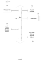
- FIG. 3 depicts a system for recharging mass transit battery electric vehicles at passenger stops, according to some example embodiments.
- FIG. 4 depicts a flowchart of operations for recharging battery electric vehicles, according to some example embodiments.
- FIG. 5 depicts a flowchart of operations for enhanced usage and pricing for recharging battery electric vehicles, according to some example embodiments.
- FIG. 6 depicts a flowchart of operations for recharging mass transit battery electric vehicles at passenger stops, according to some example embodiments.
- FIG. 7 depicts a computer system, according to some example embodiments.
- an electrical grid system supplies electrical power of a network to a number of recharging stations that can be used by operators of battery electric vehicles to recharges their vehicles.
- the electrical grid system collects usage data from the different battery electric vehicles.
- the electrical grid system can receive this data based on different types of network communications (wired and wireless). For example, the system can receive this data wireless from an onboard computer of the battery electric vehicle, a smart phone of the operator that is communicatively coupled to the onboard computer of the battery electric vehicle, etc.
- a battery electric vehicle provides its usage data (including remaining charge, current location, etc.).
- a control module of the electrical grid system can determine vehicle current charge needs and provide the driver of the battery electric vehicle with optimal recharge locations.
- the optimal recharge location can be the location having the least impact on the electrical grid, the location that is least expensive, the location that can recharge the quickest (the recharge time), the location have the least environmental impact, etc.
- GPSs Global Positioning Systems
- these conventional systems do not provide the driver with suggestions of a recharging location based on knowledge of vehicle density, price, recharge time, etc. (as described herein).
- some example embodiments provide an integrated approach for recharging of battery electric vehicles that includes providing information to the electrical grid system regarding a driver's potential recharging needs for their vehicle based on their location.
- the control module of the electrical grid system can use this data to distribute load to other parts of the electrical grid that has more capacity.
- the control module can distribute the load by suggesting alternative recharging locations for a vehicle and/or by denying recharging at particular recharging stations.
- the drivers can provide their battery electric vehicle's current charge level and destination.
- the control module of the electrical grid system can dynamically shift electrical supply on the grid to anticipate localized demand. For example, if a certain number of vehicles will require recharge in certain recharging stations and the current electrical supply for these recharging stations is insufficient, the control module can shift electrical supply from other parts of its system that will be underused during this time to these recharging stations (thereby satisfying this demand that is to occur because of upcoming recharges of these vehicles). Accordingly, because these battery electrical vehicles transmit their current charge level and proposed destination, the control module of the electrical grid system is able to more accurately predict the likelihood of the need for a recharging session at particular recharging stations.
- the drivers of the battery electric vehicles can rely on a device (e.g., onboard computer) within their vehicle or a separate device (e.g., a driver's mobile device, such as a smart phone) to determine and enter the following information about the vehicle into the electrical grid system—1) current charge level, 2) current location, and 3) planned itinerary.
- a device e.g., onboard computer
- a separate device e.g., a driver's mobile device, such as a smart phone
- the control module of the electrical grid system determines if the driver will be unable to complete the trip defined by their planned itinerary. If the driver is unable, the control module can provide an alternative itinerary, different optimal recharging locations to recharge the vehicle, etc.
- control module provides suggested recharging stations based on one or more of the following: 1) price, 2) density of vehicles at the recharging station, 3) traffic near the recharging station, 4) learned patterns established from typically-used recharging stations, 5) changes in elevations on the route, etc.
- some example embodiments incorporate dynamic pricing for power supplied at the charging stations.
- the pricing can be based on both demand and other service oriented needs.
- some example embodiments have application to mass transit battery electric vehicles (e.g., buses, trains, etc.).
- FIG. 1 depicts a system for recharging a battery electric vehicle, according to some example embodiments.
- FIG. 1 depicts a system 100 that illustrates a single battery electric vehicle (a battery electric vehicle 102 ) and a single recharging station (a recharging station 106 ).
- the system 100 can be expanded to cover any number of battery electric vehicles and recharging stations.
- the system 100 also includes public utility services 114 , private utility services 112 , a Global Positioning System (GPS) satellite 110 , and a power generator 108 .
- a mobile device 104 can be owned by an operator of the battery electric vehicle 102 and can be various types of devices (e.g., smart phone, Personal Digital Assistant (PDA), tablet computer, notebook computer, etc.).
- PDA Personal Digital Assistant
- the public utility services 114 include a server 116
- the private utility services 112 include a server 118 .
- These services can include other types of devices and computers for receiving and transmitting network communications and providing control of different parts of the system 100 (as further described below). While shown as being separate, the operations provided by the private utility services 112 and the public utility services 114 can be combined.
- the server 118 includes a control module 120 .
- the control module 120 can be software, firmware, hardware or a combination thereof.
- the control module 120 can be software that is loaded into a processor for execution therein.
- the GPS satellite 110 transmits a GPS signal 122 to at least one of the battery electric vehicle 102 and the mobile device 104 .
- the battery electric vehicle 102 can have an onboard computer.
- the onboard computer and the mobile device 104 can determine a global position of the battery electric vehicle 102 based on the GPS signal 122 .
- At least one of the battery electric vehicle 102 and the onboard computer is also communicatively coupled to the server 116 (wireless communication 124 ).
- the server 116 is communicatively coupled to the server 118 .
- the server 118 is communicatively coupled to the power generator 108 .
- the power generator 108 is communicatively coupled to the recharging station 106 to provide power to the recharging station 106 that is to be used for recharging battery electric vehicles.
- the communications between the server 116 and the server 118 , the server 118 and the power generator 108 can be wired or wireless.
- the battery electric vehicle 102 is a distance 150 from the recharging station 106 .
- the driver of the battery electric vehicle 102 provides their battery electric vehicle's current charge level and destination to the control module 120 .
- the control module 120 can dynamically shift electrical supply on the grid to anticipate localized demand. For example, if a certain number of vehicles will require recharge at the recharging station 106 and the current electrical supply for the recharging station 106 is insufficient, the control module 120 can shift electrical supply from other parts of its system that will be underused during this time to the recharging station 106 (thereby satisfying this demand that is to occur because of upcoming recharges of these vehicles).
- the power generator 108 can be supplying power to multiple recharging stations (not shown in FIG. 1 ).
- the control module 120 can transmit instructions to the power generator 108 to supply additional power to the recharging station 106 and supply less power to the other recharging stations. Accordingly, because these battery electrical vehicles transmit their current charge level and proposed destination, the control module 120 is able to more accurately predict the likelihood of the need for a recharging session at particular recharging stations.
- the driver of the battery electric vehicle 102 uses at least one the mobile device 104 and an integrated device (e.g., onboard computer) of the battery electric vehicle 102 .
- the driver of the battery electric vehicle 102 provides, to the control module 120 (through the communication 124 ) one or more of the following: 1) current charge level, 2) current location, and 3) planned itinerary.
- the control module 120 determines if the driver will be unable to complete the trip defined by their planned itinerary. If the driver is unable, the control module 102 provides an alternative itinerary, different optimal recharging locations to recharge the vehicle, etc.
- control module 120 provides, to the driver, suggested recharging stations based on one or more of the following: 1) price, 2) density of vehicles at the recharging station, 3) traffic near the recharging station, 4) learned patterns established from typically-used recharging stations, 5) changes in elevations on the route, etc.
- the control module 120 determines future charging needs of multiple battery electric vehicles (BEVs). For example, the battery electric vehicles can transmit their charging needs prior to arriving at a recharging station for a recharge session. The battery electric vehicles can also transmit an indication that a charging session is needed at a recharging station. The charging needs can be based on the current location and current charge of the battery electric vehicle and the location of a selected recharging station.
- BEVs battery electric vehicles
- the driver of the battery electric vehicle 102 is provided with an interface to interact with the electrical grid system.
- a web service or Software as a Solution (SaaS) implementation can allow for this interaction with the control module 120 , the recharging station 106 , etc. from any location.
- This interface can be provided through any type of device (e.g., smart phone, onboard computer on the battery electric vehicle, etc.).
- the control module 120 determines a charge rate for a charge station for the battery electric vehicle 102 prior to arrival. The control module 120 can then provide this charge rate to the battery electric vehicle 102 prior to arrival. The control module 120 can make this determination of the charge rate based on the number of battery electric vehicles and amount of power needed for such vehicles currently charging at the recharging station 106 , the number of battery electric vehicles and amount of power needed for such vehicles that are to arrive for charging at the recharging station 106 , the time of day, the location of the recharging station 106 , etc.
- the recharging station 106 can vary the amount of power output provided to the battery electric vehicle 102 .
- a larger power output for a given time T can cost more than a lesser power output for the same time T.
- this variable power output is used to provide power to the battery electric vehicle 102 in a charge time (t charge ) that satisfies a required time to reach the desired recharging station or final destination (T total ).
- t charge charge time
- the power output at the recharging station 106 can be increased to lower the charge time so that the total time can be met. Conversely, if the time of the commute is less, the power output at the recharging station 106 can be decreased to increase the charge time so that the total time can be met.
- control module 120 provides the driver of the battery electric vehicle 102 with environmental impact feedback information for a charging request for a selected charge session and projected impact at alternative times or recharging locations. For example, power being provided at a recharging station from solar or wind would have less environmental impact than power being provided by a different recharging station that is derived from traditional power sources (e.g., hydrocarbons).
- traditional power sources e.g., hydrocarbons
- the control module 120 incorporate dynamic pricing for power supplied at the recharging stations.
- the pricing can be based on both demand and other service oriented needs.
- Two common denominators for drivers of battery electric vehicles include 1) locations available for recharging, and 2) the time required to recharge.
- a pricing model can be based on these two denominators.
- the control module 120 enables a driver of a battery electric vehicle to reserve a spot at a particular recharging station for a specific time and for a specific time period.
- a driver of a battery electric vehicle can reserve a spot at a particular charging station for a specific time period (independent of a specific time).
- a driver of a battery electric vehicle can also reserve a spot at for a specific time period (independent of a specific time and independent of a particular charging station).
- the driver can charge their battery electric vehicle for a set time period (e.g., one hour) at any recharging location at any time.
- the driver of a battery vehicle can purchases these different types of recharges and be provided with some type of electronic token that is presented for redemption.
- the driver can transmit the electronic token to the control module 120 for redemption through a wireless communication using their smart phone, the onboard computer of the battery electric vehicle, etc.
- This electronic token communication can also be performed in real time, directly or indirectly through an intermediary service (e.g., electronic advertisements).
- the control module 120 varies the pricing for power based on willingness of the driver to accept an indeterminate charge time.
- the driver of the battery electric vehicle 102 can purchase an 80% recharge of their battery electric vehicle 102 at the recharging station 106 .
- the time period required to charge to 80% is indeterminate but within a certain range.
- Charge time can vary. For example, charge time can increase or decrease dynamically based on real time demand. Charge time can also increase or decrease dynamically based on the driver's willingness to pay a premium for preferential or unrestricted service.
- FIG. 2 depicts a segmentation of a geographical location having recharging stations for recharging battery electric vehicles, according to some example embodiments.
- a segmentation 200 can be of any type of geographical location having recharging stations therein.
- the geographical location can be a part of a city, an entire city, a county, a state, a country, etc.
- the segmentation 200 includes four different sectors—a sector A 202 , a sector B 204 , a sector C 206 , and a sector D 208 .
- the different sectors have varying density of recharging locations and battery electric vehicles.
- the battery electric vehicles are not constrained to a given sector and can travel among any of the sectors.
- the sector A 202 includes two recharging stations—a recharging station 210 and a recharging station 212 .
- there are six battery electric vehicles in the sector A 202 a battery electric vehicle 240 , a battery electric vehicle 242 , a battery electric vehicle 246 , a battery electric vehicle 248 , a battery electric vehicle 250 , and a battery electric vehicle 252 .
- the sector B 204 includes one recharging station—a recharging station 214 .
- there are two battery electric vehicles in the sector B 204 a battery electric vehicle 254 and a battery electric vehicle 256 .
- the sector C 206 includes five recharging stations—a recharging station 216 , a recharging station 218 , a recharging station 220 , a recharging station 222 , and a recharging station 224 .
- there are nine battery electric vehicles in the sector C 206 a battery electric vehicle 258 , a battery electric vehicle 260 , a battery electric vehicle 262 , a battery electric vehicle 264 , a battery electric vehicle 266 , a battery electric vehicle 268 , a battery electric vehicle 270 , a battery electric vehicle 272 , and a battery electric vehicle 274 .
- the sector D 208 includes three recharging stations—a recharging station 226 , a recharging station 228 , and a recharging station 230 .
- there are two battery electric vehicles in the sector D 208 —a battery electric vehicle 276 and a battery electric vehicle 278 .
- the control module 120 (shown in FIG. 1 ) dynamically distributes the power to the different recharging stations based on usage data that is received from the battery electric vehicles in real time.
- the control module 120 leverages the knowledge of the future charging needs and locations of the battery electric vehicles to accurately project power needs some time in the future in variable increments of time. Based on this knowledge, the control module 120 redistributes power on the electrical grid that supplies power to the various recharging stations used by the battery electric vehicles. The control module 120 provides more power to specific recharging stations, sectors, etc. on the power grid or increase associated generating capacity (based on anticipation of the need rather than being reactive to power needs on the power grid). For example, based on usage data received from the different battery electric vehicles, the control module 120 shifts power being supplied to the recharging stations 226 - 230 in the sector D to the recharging stations 210 - 210 in the sector A.
- the control module 120 (see FIG. 1 ) provides a location based service that determines the current power needs of a battery electric vehicle at location X and the calculated power needs of the battery electric vehicle once the destination of the desired charging station is reached (location X+ ⁇ X).
- the control module 120 determines the most desirable charging station for a battery electric vehicle based on a number of factors (e.g., current charging needs, current location, environmental conditions, cost basis, etc.). For example, for the battery electric vehicle 256 , the recharging station 214 is close but requires the battery electric vehicle 256 is travel up a hill, while the recharging station 226 can be farther and not require the battery electric vehicle 256 to travel up a hill. In such a situation, the control module 120 can recommend the recharging station 226 can be the most desirable recharging station for the battery electric vehicle 256 .
- control module 120 leverages the information about the charge time (t charge ) and the time of the compute (t commute ) for the different battery electric vehicles that use the electrical grid in order to redistribute the power at the different charging stations.
- control module 120 can determine the power output at each of a selected series of recharging stations in order to fulfill the charge level requirements of itineraries of the different battery electric vehicles (taking into consideration the charge times at each station).
- the power output at the recharging stations affects the price. For example, power output X per unit of time costs more than power output Y per same unit of time (where X is greater than Y).
- the pricing for power supplied at recharging stations can also be based on congestion relative to the recharging stations. The higher congestion for usage of power at the recharging station causes the price of the power supplied to increase.
- FIG. 3 depicts a system for recharging mass transit battery electric vehicles at passenger stops, according to some example embodiments.
- FIG. 3 depicts a system 300 for recharging a mass transit battery electric vehicle 302 .
- the system 300 includes utility services 304 that include a server 306 . These services can include other types of devices and computers for receiving and transmitting network communications and providing control of different parts of the system 300 (as further described below).
- the server 306 includes a control module 308 .
- the control module 308 can be software, firmware, hardware or a combination thereof.
- the control module 308 can be software that is loaded into a processor for execution therein.
- the system 300 also includes a GPS satellite 310 transmits a GPS signal 322 to the mass transit battery electric vehicle 302 .
- the mass transit battery electric vehicle 302 can have an onboard computer.
- the onboard computer determines a global position of the mass transit battery electric vehicle 302 based on the GPS signal 322 .
- the onboard computer of the mass transit battery electric vehicle 302 is also communicatively coupled to the server 306 (wireless communication 324 ).
- the mass transit battery electric vehicle 302 has a route that includes a number of passenger stops that also serve as recharging stations for recharging the mass transit battery electric vehicle 302 —a passenger stop 310 , a passenger stop 312 , a passenger stop 314 , a passenger stop 316 , a passenger stop 318 , and a passenger stop 320 .
- the mass transit battery electric vehicle 302 has a circular route. The circular route is configured such that the order of the passenger stops are the passenger stop 310 , the passenger stop 312 , the passenger stop 314 , the passenger stop 316 , the passenger stop 318 , the passenger stop 320 , and returning to the passenger stop 310 .
- the server 306 is communicatively coupled to each of the passenger stops. In FIG. 3 , these communications are shown as a wireless communication. However, such communications can also be wired.
- the server 306 is communicatively coupled to the passenger stop 310 through a communication 326 .
- the server 306 is communicatively coupled to the passenger stop 312 through a communication 328 .
- the server 306 is communicatively coupled to the passenger stop 314 through a communication 330 .
- the server 306 is communicatively coupled to the passenger stop 316 through a communication 332 .
- the server 306 is communicatively coupled to the passenger stop 318 through a communication 334 .
- the server 306 is communicatively coupled to the passenger stop 320 through a communication 336 .
- the mass transit battery electric vehicle 302 needs to maintain a certain charge level to be able to arrive at the next stop in its route.
- the control module 308 determines the amount of time that the mass transit battery electric vehicle 302 is to be at a passenger stop and the amount of power needed to deliver the required minimum level of charge in the time that the mass transit battery electric vehicle 302 is at the stop.
- the minimum level of charge would be the amount of charge needed to reach the next stop.
- This minimum level of charge can include some reserve and can be based on various factors (e.g., traffic, weather, number of passengers, amount of power to be expended, etc.).
- the power output for a same vehicle can vary among the different stops (e.g., stop A requires 1000 volts, stop B requires 220 volts, stop C requires 750 volts, etc.).
- the passenger stops transmit to the control module 308 various data to enable the control module 308 to determine this minimum level of charge for the mass transit battery electric vehicle 302 at the next passenger stop. For example, all, some or only the next passenger stop transmits to the control module 308 the number of waiting passengers, the average load time for the stop, power output options, etc.
- a given passenger stop can transmit its data when the passenger stop is the next stop for the mass transit battery electric vehicle 302 .
- the passenger stop transmits its data (through the communication 328 ) to the control module 308 .
- the passenger stops provide average load time, number of waiting passengers, etc. based on past stops at this particular passenger stop for a particular day, time of day, etc.
- the passenger stops can provide the number of actual passengers waiting to board.
- the passenger can register with a device (e.g., a scanner) that is communicatively coupled to the control module 208 while waiting to board.
- the control module 208 can then receive the number of register passengers. This number can be update each time a new passenger is registered.
- the control module 308 also receives data from the mass transit battery electric vehicle 302 (the communication 324 ) to enable the control module 308 to determine this minimum level of charge for the mass transit battery electric vehicle 302 at the next passenger stop.
- the mass transit battery electric vehicle 302 transmits its current charge, charge capacity and distance to the next stop in the route.
- the control module 308 can then determine the power output at the next and subsequent recharging stations to satisfy the required charge level in a specified amount of time (the load time).
- the control module 308 can transmit this information to at least one the mass transit battery electric vehicle 302 and the next passenger stop. For the scenario where no scheduled stops are planned for a certain number of stops, the control module 308 would configure the route such that the current or previous recharging sessions would need to deliver the appropriate amount of power to at least maintain power to the next scheduled stop.
- the control module 308 would configure the passenger stop 312 to recharge the mass transit battery electric vehicle 302 for a longer period of time. Accordingly, the control module 308 can configure recharge times for an upcoming stop based on anticipated stop times for one or more passenger stops thereafter.
- system 300 is illustrated in reference to a bus, some example embodiments are applicable to any type mass transit vehicle that includes stops for passenger pickup and drop-off (e.g., trains, trolleys, etc.).
- electrified trains and trolleys would no longer need continuous contact with a power source.
- strategically placed charging stations can be positioned to maintain a certain charge level for these trains and trolleys.
- an electrified third rail would not be required.
- trolleys there would be no need for the supporting infrastructure for overhead electrified wires.
- these systems for trains and trolleys can be based on power on demand (where power is supplied at the recharging stations when required and not a constant supply of power like conventional systems.
- the recharging station deliver power to the mass transit battery electric vehicles through a contact-less mechanism (e.g., using induction).
- the recharging station can also determine if power needs to be delivered when a battery electric vehicle is in a position where charge can be delivered.
- Such embodiments are useful for mass transit where the recharging stations are the passenger stops. In such situations, requiring delivery of power through corded charge equipment can take too much time at each passenger stop where power is needed.
- Such embodiments for contact-less delivery of power are also applicable to non-mass transit battery electric vehicles.
- the operations can be performed by logic not described in the block diagrams.
- the operations can be performed by executing instructions residing on machine-readable media (e.g., software), while in other embodiments, the operations can be performed by hardware and/or other logic (e.g., firmware).
- the operations can be performed in series, while in other embodiments, one or more of the operations can be performed in parallel.
- some embodiments can perform less than all the operations shown in any flowchart.
- FIG. 4 depicts a flowchart of operations for recharging battery electric vehicles, according to some example embodiments.
- FIG. 4 depicts a flowchart 400 that can be performed by the control module 120 of FIG. 1 .
- the operations of the flowchart 400 are described in reference to FIGS. 1 and 2 .
- the operations of the flowchart 400 begin at block 402 .
- the control module 120 receives from a number of battery electric vehicles usage data that comprises a current charge level, a current location, and a planned itinerary that includes a destination. For example with reference to FIG. 2 , the control module 120 receives this usage data from some or all of the battery electric vehicles 240 - 278 . Operations of the flowchart 400 continue at block 404 .
- the control module 120 determines anticipated electrical loads in the number of sectors of the electrical grid system based on the usage data of the number of battery electric vehicles. In particular, the control module 120 can determine that the sector A 202 will require more power from the electrical grid for the recharging stations 210 - 212 in the next hour for at least two hours. Similarly, the control module 120 can determine that the sector D 208 will require less power from the electrical grid for the recharging stations 226 - 230 during the same time period.
- the usage data can include current charge level, charge capacity, location, and planned itinerary.
- the control module 120 determines that a given battery electric vehicle is required to use a given recharging station because this is the only recharging station close enough to enable the driver to recharge their vehicle prior to the charge levels being depleted.
- the control module 120 receives the usage data from the battery electric vehicle 278 . Based on this data, the control module 120 determines that the battery electric vehicle 178 is headed west to a final destination beyond the sector C 206 .
- the control module 120 can receive this usage data from multiple battery electric vehicles to determine amount of usage, time period of use, amount of power needed, etc, at the different recharging stations. Based on these anticipated electrical loads, the control module 120 can perform one or more of the operations at blocks 406 - 412 (described below). For example, in some scenarios, the control module 120 performs the operations at block 406 and 412 . In another scenario, the control module 120 performs the operations at blocks 406 , 408 , 410 , and 412 . Operations of the flowchart 400 continue at block 406 .
- the control module 120 redistributes the electrical supply on an electrical grid system to at least one sector of the number of sectors based on the anticipated electrical loads, prior to actual usage defined by the usage data by the number of battery electrical vehicles. For example, with reference to FIG. 2 , the control module 120 can shift power being supplied to the recharging stations 210 - 212 in the sector A 202 to the recharging stations 216 - 224 in the sector C 206 for the next six hours because the usage data of the battery electric vehicles indicate that more power is needed in the sector C 206 to meet demand for those vehicles planning to recharge in the recharging stations therein for the next six hours. Operations of the flowchart 400 continue at block 408 .
- the control module 120 transmits to a battery electric vehicle a recommended recharging station among the number of recharging stations for actual usage by the battery electric vehicle.
- the control module 120 can recommend a recharging station to a battery electric vehicle based on its own usage data and other vehicles' usage data.
- the control module 120 can send a communication to the battery electric vehicle 252 to recharge at the recharging station 210 instead of the recharging station 212 because all of the spots are being used in the recharging station 212 , the cost is higher at the recharging station 212 , etc.
- Operations of the flowchart 400 continue at block 410 .
- the control module 120 denies access to at least one recharging station of the number of recharging stations by at least one battery electric vehicle of the number of battery electric vehicles based on the anticipated electrical loads in the number of sectors of the electrical grid system.
- the control module 120 can deny access because there would be insufficient power to accommodate the anticipated electrical load.
- the control module 120 can deny access to the recharging station 210 by the battery electric vehicle 240 because the battery electric vehicles 250 and 242 are about to access the recharging station 210 and use the available power to recharge.
- the control module 120 can provide a recommendation to the battery electric vehicle 240 to use the recharging station 212 (as described at block 408 ). Operations of the flowchart 400 continue at block 412 .
- the control module 120 dynamically varies charge rates for recharging at the number of recharging stations based on the anticipated electrical loads in the number of sectors of the electrical grid system, wherein the charge rates are variable across the number of recharging stations. For example with reference to FIG. 2 , the control module 120 can increase the charge rates for the recharging stations 216 - 224 because of level of anticipated demand. Alternatively, the control module 120 can decrease the charge rates for the recharging station 228 because of a lack of anticipated demand. Operations of the flowchart 400 are complete.
- FIG. 5 depicts a flowchart of operations for enhanced usage and pricing for recharging battery electric vehicles, according to some example embodiments.
- FIG. 5 depicts a flowchart 500 that can be performed by the control module 120 of FIG. 1 .
- the operations of the flowchart 500 are described in reference to FIG. 1 .
- the operations of the flowchart 500 begin at block 502 .
- the control module 120 presents an electronic token for purchase to a driver of a battery electric vehicle.
- the control module 120 can transmit an offer to purchase the electronic token based on an advertisements, email, text message, direct message, etc. to the mobile device of the driver, the onboard computer of the battery electric vehicle associated with the driver, etc.
- the electronic token can represent a given recharge time.
- the electronic token can enable the driver of a battery electric vehicle to reserve a spot at a particular recharging station for a specific time and for a specific time period.
- the electronic token enables the driver to reserve a spot at a particular recharging station for a specific time period (independent of a specific time).
- the electronic token enables the driver to reserve a spot for a specific time period (independent of a specific time and independent of a particular recharging station).
- the driver can charge their battery electric vehicle for a set time period (e.g., one hour) at any charging location at any time. Operations of the flowchart 500 continue at block 504 .
- the control module 120 determines whether the driver has purchased the electronic token.
- the control module 120 can receive a transmission from the driver's mobile device or onboard computer of their battery electric vehicle that confirms purchase. For example, the driver can provide their credit card number, debit card number, etc. through the electronic transmission. If the driver does not purchases the electronic token, operations of the flowchart return to block 502 , where the electronic token can again be presented to the driver. If the driver does purchase the electronic token, operations of the flowchart 500 continue at block 506 .
- the control module 120 transmits the electronic token to at least one of a mobile device of the driver and a device associated with the battery electric vehicle.
- the control module 120 can send the electronic token through the wireless communication 124 to the mobile device 104 or the device (e.g., onboard computer) of the battery electric vehicle 102 for storage in a nonvolatile machine readable medium. Operations of the flowchart 500 continue at block 508 .
- the control module 120 receives the purchased electronic token from at least one of a mobile device of the driver and a device associated with the battery electric vehicle. With reference to FIG. 1 , the control module 120 receives the purchased electronic token through the wireless communication 124 from the mobile device of the driver and the device associated with the battery electric vehicle. Operations of the flowchart 500 continue at block 510 .
- the control module 120 reserves a reserve spot at the number of recharging stations to recharge the battery electric vehicle based on the electronic token.
- the reserving of the spot is for a guaranteed time period based on a monetary value of the electronic token and is unrestricted with regard to a recharging station and a time or day restriction. Accordingly, the driver can arrive at any recharging station and is guaranteed a spot for recharging (without having to wait).
- the value of the electronic token can vary depending on its usage.
- the control module 120 can present an option to a driver having the electronic token to redeem the token at the closest recharging station within a defined time period (e.g., one hour). In return, the electronic token retains a percentage of its value. To illustrate, the driver can recharge now for one hour (the value of the token) and retain 30 minutes of recharge time anywhere and anytime else. Operations of the flowchart 500 are complete.
- FIG. 6 depicts a flowchart of operations for recharging mass transit battery electric vehicles at passenger stops, according to some example embodiments.
- FIG. 6 depicts a flowchart 600 that can be performed by the control module 308 of FIG. 3 .
- the operations of the flowchart 600 are described in reference to FIG. 3 .
- the operations of the flowchart 600 begin at block 602 .
- the control module 308 receives, from a mass transit battery electric vehicle while in transit along a route having a number of stops for passenger pickup, a charge capacity, a current charge level and a current location. With reference to FIG. 3 , the control module 308 receives this data from the mass transit battery electric vehicle 302 through the wireless communication 324 . Operations of the flowchart 600 continue at block 604 .
- the control module 308 receives, from a next stop along the route for the mass transit battery electric vehicle, an anticipated stop time at the next stop for the mass transit battery electric vehicle.
- the control module 308 receives the anticipated stop time from the passenger stop 312 .
- the anticipated stop time can be based on the number of passengers registered to get on and get off the mass transit battery electric vehicle 302 at the passenger stop 312 . Operations of the flowchart 600 continue at block 606 .
- the control module 308 determines a required power output to be supplied to the mass transit battery electric vehicle by the recharging station at the next stop based on the current charge level.
- the required power output includes an amount of power to be supplied within the anticipated stop time at the next stop and includes the amount of power needed to satisfy a minimum amount of charge to enable the mass transit battery electric vehicle to arrive at a subsequent stop after the next stop.
- the control module 308 can determine the minimum amount of charge needed at the passenger stop 312 to enable the mass transit battery electric vehicle 302 to arrive at the passenger stop 314 (assuming that the mass transit battery electric vehicle 302 stops at the passenger stop 314 ). Operations of the flowchart 600 continue at block 608 .
- the control module 308 transmits, to the recharging station at the next stop, the required power output to be supplied to the mass transit battery electric vehicle by the recharging station.
- the control module 308 transmits, to the recharging station 312 , the required power output (including the amount of power and time) to be supplied to the mass transit battery electric vehicle 302 at the recharging station 312 . Operations of the flowchart 600 are complete.
- aspects of the present inventive subject matter may be embodied as a system, method or computer program product. Accordingly, aspects of the present inventive subject matter may take the form of an entirely hardware embodiment, an entirely software embodiment (including firmware, resident software, micro-code, etc.) or an embodiment combining software and hardware aspects that may all generally be referred to herein as a “circuit,” “module” or “system.” Furthermore, aspects of the present inventive subject matter may take the form of a computer program product embodied in one or more computer readable medium(s) having computer readable program code embodied thereon.
- the computer readable medium may be a computer readable signal medium or a computer readable storage medium.
- a computer readable storage medium may be, for example, but not limited to, an electronic, magnetic, optical, electromagnetic, infrared, or semiconductor system, apparatus, or device, or any suitable combination of the foregoing.
- a computer readable storage medium may be any tangible medium that can contain, or store a program for use by or in connection with an instruction execution system, apparatus, or device.
- a computer readable signal medium may include a propagated data signal with computer readable program code embodied therein, for example, in baseband or as part of a carrier wave. Such a propagated signal may take any of a variety of forms, including, but not limited to, electro-magnetic, optical, or any suitable combination thereof.
- a computer readable signal medium may be any computer readable medium that is not a computer readable storage medium and that can communicate, propagate, or transport a program for use by or in connection with an instruction execution system, apparatus, or device.
- Program code embodied on a computer readable medium may be transmitted using any appropriate medium, including but not limited to wireless, wireline, optical fiber cable, RF, etc., or any suitable combination of the foregoing.
- Computer program code for carrying out operations for aspects of the present inventive subject matter may be written in any combination of one or more programming languages, including an object oriented programming language such as Java, Smalltalk, C++ or the like and conventional procedural programming languages, such as the “C” programming language or similar programming languages.
- the program code may execute entirely on the user's computer, partly on the user's computer, as a stand-alone software package, partly on the user's computer and partly on a remote computer or entirely on the remote computer or server.
- the remote computer may be connected to the user's computer through any type of network, including a local area network (LAN) or a wide area network (WAN), or the connection may be made to an external computer (for example, through the Internet using an Internet Service Provider).
- LAN local area network
- WAN wide area network
- Internet Service Provider for example, AT&T, MCI, Sprint, EarthLink, MSN, GTE, etc.
- These computer program instructions may also be stored in a computer readable medium that can direct a computer, other programmable data processing apparatus, or other devices to function in a particular manner, such that the instructions stored in the computer readable medium produce an article of manufacture including instructions which implement the function/act specified in the flowchart and/or block diagram block or blocks.
- the computer program instructions may also be loaded onto a computer, other programmable data processing apparatus, or other devices to cause a series of operational steps to be performed on the computer, other programmable apparatus or other devices to produce a computer implemented process such that the instructions which execute on the computer or other programmable apparatus provide processes for implementing the functions/acts specified in the flowchart and/or block diagram block or blocks.
- FIG. 7 depicts a computer system, according to some example embodiments.
- a computer system 700 can be representative of a node that is coupled to one or more link-local zones (as described herein).
- the computer system 700 includes a processor unit 701 (possibly including multiple processors, multiple cores, multiple nodes, and/or implementing multi-threading, etc.).
- the computer system 700 includes a volatile machine readable medium 707 .
- the volatile machine readable medium 707 can be system memory (e.g., one or more of cache, SRAM, DRAM, zero capacitor RAM, Twin Transistor RAM, eDRAM, EDO RAM, DDR RAM, EEPROM, NRAM, RRAM, SONOS, PRAM, etc.) or any one or more of the above already described possible realizations of machine-readable media.
- system memory e.g., one or more of cache, SRAM, DRAM, zero capacitor RAM, Twin Transistor RAM, eDRAM, EDO RAM, DDR RAM, EEPROM, NRAM, RRAM, SONOS, PRAM, etc.
- the computer system 700 also includes a bus 703 (e.g., PCI, ISA, PCI-Express, HyperTransport®, InfiniBand®, NuBus, etc.), a network interface 705 (e.g., an ATM interface, an Ethernet interface, a Frame Relay interface, SONET interface, wireless interface, etc.), and a nonvolatile machine-readable medium 709 (e.g., optical storage, magnetic storage, etc.).
- the computer system 700 includes a control module 725 that can be representative of the control module 120 of FIG. 1 and the control module 308 of FIG. 3 and can perform the operations for control power distribution and the battery electric vehicles (as described herein).
- any one of these functionalities may be partially (or entirely) implemented in hardware and/or on the processing unit 701 .
- the functionality may be implemented with an application specific integrated circuit, in logic implemented in the processing unit 701 , in a co-processor on a peripheral device or card, etc.
- realizations may include fewer or additional components not illustrated in FIG. 7 (e.g., video cards, audio cards, additional network interfaces, peripheral devices, etc.).
- the processor unit 701 , the nonvolatile machine readable medium 709 , the volatile machine-readable medium 707 , the network interface 705 , and the interface configuration module 725 are coupled to the bus 703 . Although illustrated as being coupled to the bus 703 , the volatile machine-readable medium 707 can be coupled to the processor unit 701 .
Landscapes
- Engineering & Computer Science (AREA)
- Power Engineering (AREA)
- Business, Economics & Management (AREA)
- Transportation (AREA)
- Mechanical Engineering (AREA)
- Physics & Mathematics (AREA)
- General Physics & Mathematics (AREA)
- Human Resources & Organizations (AREA)
- Economics (AREA)
- Strategic Management (AREA)
- Tourism & Hospitality (AREA)
- Automation & Control Theory (AREA)
- General Business, Economics & Management (AREA)
- Theoretical Computer Science (AREA)
- Entrepreneurship & Innovation (AREA)
- Marketing (AREA)
- Radar, Positioning & Navigation (AREA)
- Electromagnetism (AREA)
- Development Economics (AREA)
- Life Sciences & Earth Sciences (AREA)
- Quality & Reliability (AREA)
- Operations Research (AREA)
- Sustainable Development (AREA)
- Health & Medical Sciences (AREA)
- Sustainable Energy (AREA)
- Computer Networks & Wireless Communication (AREA)
- General Engineering & Computer Science (AREA)
- Primary Health Care (AREA)
- General Health & Medical Sciences (AREA)
- Educational Administration (AREA)
- Game Theory and Decision Science (AREA)
- Public Health (AREA)
- Water Supply & Treatment (AREA)
- Charge And Discharge Circuits For Batteries Or The Like (AREA)
- Electric Propulsion And Braking For Vehicles (AREA)
- Supply And Distribution Of Alternating Current (AREA)
- Remote Monitoring And Control Of Power-Distribution Networks (AREA)
Priority Applications (10)
| Application Number | Priority Date | Filing Date | Title |
|---|---|---|---|
| US13/174,227 US9718371B2 (en) | 2011-06-30 | 2011-06-30 | Recharging of battery electric vehicles on a smart electrical grid system |
| EP12729439.5A EP2627532B1 (en) | 2011-06-30 | 2012-06-11 | Recharging of battery electric vehicles on a smart electrical grid system |
| CA2836001A CA2836001C (en) | 2011-06-30 | 2012-06-11 | Recharging of battery electric vehicles on a smart electrical grid system |
| PCT/EP2012/060964 WO2013000687A1 (en) | 2011-06-30 | 2012-06-11 | Recharging of battery electric vehicles on a smart electrical grid system |
| CN201280025500.XA CN103562001B (zh) | 2011-06-30 | 2012-06-11 | 电池电动车辆在智能电网系统上的再充电 |
| SG2013046636A SG191209A1 (en) | 2011-06-30 | 2012-06-11 | Recharging of battery electric vehicles on a smart electrical grid system |
| JP2014517565A JP2014525225A (ja) | 2011-06-30 | 2012-06-11 | 電池式電気自動車を再充電するための方法、装置、コンピュータ・プログラム |
| US13/777,088 US9274540B2 (en) | 2011-06-30 | 2013-02-26 | Recharging of battery electric vehicles on a smart electrical grid system |
| US15/001,926 US10513192B2 (en) | 2011-06-30 | 2016-01-20 | Recharging of battery electric vehicles on a smart electrical grid system |
| US15/610,044 US11159043B2 (en) | 2011-06-30 | 2017-05-31 | Recharging of battery electric vehicles on a smart electrical grid system |
Applications Claiming Priority (1)
| Application Number | Priority Date | Filing Date | Title |
|---|---|---|---|
| US13/174,227 US9718371B2 (en) | 2011-06-30 | 2011-06-30 | Recharging of battery electric vehicles on a smart electrical grid system |
Related Child Applications (2)
| Application Number | Title | Priority Date | Filing Date |
|---|---|---|---|
| US13/777,088 Continuation US9274540B2 (en) | 2011-06-30 | 2013-02-26 | Recharging of battery electric vehicles on a smart electrical grid system |
| US15/610,044 Continuation US11159043B2 (en) | 2011-06-30 | 2017-05-31 | Recharging of battery electric vehicles on a smart electrical grid system |
Publications (2)
| Publication Number | Publication Date |
|---|---|
| US20130006677A1 US20130006677A1 (en) | 2013-01-03 |
| US9718371B2 true US9718371B2 (en) | 2017-08-01 |
Family
ID=46354208
Family Applications (4)
| Application Number | Title | Priority Date | Filing Date |
|---|---|---|---|
| US13/174,227 Active 2033-01-30 US9718371B2 (en) | 2011-06-30 | 2011-06-30 | Recharging of battery electric vehicles on a smart electrical grid system |
| US13/777,088 Active US9274540B2 (en) | 2011-06-30 | 2013-02-26 | Recharging of battery electric vehicles on a smart electrical grid system |
| US15/001,926 Active 2034-03-06 US10513192B2 (en) | 2011-06-30 | 2016-01-20 | Recharging of battery electric vehicles on a smart electrical grid system |
| US15/610,044 Active 2033-01-01 US11159043B2 (en) | 2011-06-30 | 2017-05-31 | Recharging of battery electric vehicles on a smart electrical grid system |
Family Applications After (3)
| Application Number | Title | Priority Date | Filing Date |
|---|---|---|---|
| US13/777,088 Active US9274540B2 (en) | 2011-06-30 | 2013-02-26 | Recharging of battery electric vehicles on a smart electrical grid system |
| US15/001,926 Active 2034-03-06 US10513192B2 (en) | 2011-06-30 | 2016-01-20 | Recharging of battery electric vehicles on a smart electrical grid system |
| US15/610,044 Active 2033-01-01 US11159043B2 (en) | 2011-06-30 | 2017-05-31 | Recharging of battery electric vehicles on a smart electrical grid system |
Country Status (7)
| Country | Link |
|---|---|
| US (4) | US9718371B2 (ja) |
| EP (1) | EP2627532B1 (ja) |
| JP (1) | JP2014525225A (ja) |
| CN (1) | CN103562001B (ja) |
| CA (1) | CA2836001C (ja) |
| SG (1) | SG191209A1 (ja) |
| WO (1) | WO2013000687A1 (ja) |
Cited By (9)
| Publication number | Priority date | Publication date | Assignee | Title |
|---|---|---|---|---|
| US20200070665A1 (en) * | 2018-08-28 | 2020-03-05 | Ii-Vi Delaware, Inc. | Adaptive Reservoir Charging Station |
| US11091055B2 (en) | 2019-05-10 | 2021-08-17 | GM Global Technology Operations LLC | Intelligent motor vehicles, charging systems, and control logic for governing vehicle grid integration operations |
| US11127056B2 (en) | 2017-11-30 | 2021-09-21 | Honda Motor Co., Ltd. | System and method for determining at least one demand response overhead percentage |
| US11152814B2 (en) | 2019-11-22 | 2021-10-19 | GM Global Technology Operations LLC | Mobile charging stations with fuel-cell generators for electric-drive vehicles |
| US11159043B2 (en) | 2011-06-30 | 2021-10-26 | International Business Machines Corporation | Recharging of battery electric vehicles on a smart electrical grid system |
| US11210751B2 (en) | 2020-01-14 | 2021-12-28 | International Business Machines Corporation | Targeting energy units in a blockchain |
| WO2022159952A1 (en) * | 2021-01-20 | 2022-07-28 | Enel X S.R.L. | Electric vehicle charging systems, methods, and techniques |
| US11827117B2 (en) | 2021-11-05 | 2023-11-28 | GM Global Technology Operations LLC | Intelligent charging systems and control logic for crowdsourced vehicle energy transfer |
| US11945329B2 (en) | 2022-05-02 | 2024-04-02 | GM Global Technology Operations LLC | Intelligent vehicle systems and control logic for battery charge control and information display |
Families Citing this family (88)
| Publication number | Priority date | Publication date | Assignee | Title |
|---|---|---|---|---|
| US8996212B2 (en) | 2011-07-26 | 2015-03-31 | Gogoro Inc. | Apparatus, method and article for providing vehicle diagnostic data |
| TWI537860B (zh) * | 2011-07-26 | 2016-06-11 | 英屬開曼群島商睿能創意公司 | 用於在一預訂電力儲存器件收集、充電及分配機器處預訂電力儲存器件之裝置、方法及物品 |
| US20150039391A1 (en) * | 2011-08-16 | 2015-02-05 | Better Place GmbH | Estimation and management of loads in electric vehicle networks |
| US9348381B2 (en) | 2011-10-19 | 2016-05-24 | Zeco Systems Pte Ltd | Methods and apparatuses for charging of electric vehicles |
| US8515865B1 (en) * | 2012-05-26 | 2013-08-20 | At&T Intellectual Property I, L.P. | Methods, systems, and products for charging batteries |
| CN104981958B (zh) * | 2012-07-23 | 2018-01-19 | 康奈尔大学 | 电动车辆系统的大规模充电 |
| US10256631B2 (en) * | 2013-03-04 | 2019-04-09 | University of Vemont and State Agricultural College | Systems and methods for random-access power management using packetization |
| US8862404B2 (en) * | 2013-03-13 | 2014-10-14 | Ford Global Technologies, Llc | Electric vehicle emergency recharge assistance |
| US10279697B2 (en) | 2013-08-29 | 2019-05-07 | Honda Motor Co., Ltd. | System and method for estimating a charge load |
| US20150165915A1 (en) * | 2013-12-16 | 2015-06-18 | Honda Motor Co., Ltd. | Vehicle charging system |
| JP6081941B2 (ja) * | 2014-02-28 | 2017-02-15 | 三菱重工業株式会社 | 電力需要予測装置、電力供給システム、電力需要予測方法及びプログラム |
| WO2015160937A1 (en) * | 2014-04-15 | 2015-10-22 | Shant Hovnanian | Mobile system for generation, storage, and provision of electrical power |
| US9409492B2 (en) | 2014-04-21 | 2016-08-09 | Honda Motor Co., Ltd. | Method for precise demand response and control, and a system thereof |
| US20170036560A1 (en) * | 2014-04-22 | 2017-02-09 | Nec Europe Ltd. | Method for load balancing of charging stations for mobile loads within a charging stations network and a charging stations network |
| PL3134342T3 (pl) * | 2014-04-22 | 2021-01-11 | Prysmian S.P.A. | Kontener transportowy do przewozu kabli |
| US10552923B2 (en) * | 2014-05-08 | 2020-02-04 | Honda Motor Co., Ltd. | Electric vehicle charging control system |
| US10845822B2 (en) * | 2014-10-31 | 2020-11-24 | Clearpath Robotics Inc. | Systems and methods for utilizing fleets of robots |
| CN104505822A (zh) * | 2014-11-20 | 2015-04-08 | 国家电网公司 | 供电配置方法及装置 |
| US11038361B2 (en) * | 2015-03-16 | 2021-06-15 | Lenovo (Singapore) Pte. Ltd. | Battery with cathode materials for charging at different rates |
| US10611251B2 (en) * | 2015-11-13 | 2020-04-07 | Nio Usa, Inc. | Distributed processing network for rechargeable electric vehicle tracking and routing |
| US10160339B2 (en) | 2015-11-13 | 2018-12-25 | Nio Usa, Inc. | Smart grid management |
| US10131238B2 (en) | 2015-11-13 | 2018-11-20 | Nio Usa, Inc. | Charging transmission line under roadway for moving electric vehicle |
| US20170169366A1 (en) * | 2015-12-14 | 2017-06-15 | Google Inc. | Systems and Methods for Adjusting Ride-Sharing Schedules and Routes |
| US11214157B2 (en) * | 2015-12-30 | 2022-01-04 | Proterra Inc. | Electric vehicle charging to reduce utility cost |
| US20170308948A1 (en) * | 2016-04-25 | 2017-10-26 | Ford Global Technologies, Llc | Electrified vehicle activity center ranking |
| DE112016006782T5 (de) * | 2016-05-25 | 2019-01-24 | Ford Global Technologies, Llc | Verfahren und Vorrichtungen zum Aufladen von Elektrofahrzeugen |
| US10733810B2 (en) | 2016-06-28 | 2020-08-04 | Conduent Business Services, Llc | Method and system for managing parking violations by vehicles in parking areas in real-time |
| DE102016212026A1 (de) * | 2016-07-01 | 2018-01-04 | Bayerische Motoren Werke Aktiengesellschaft | Verfahren und Steuereinheit zur Stabilisierung eines Versorgungsnetzes |
| US20190228351A1 (en) | 2018-01-23 | 2019-07-25 | Erik M. Simpson | Electronic forward market exchange for transportation seats and capacity in transportation spaces and vehicles |
| US11823090B2 (en) | 2016-09-15 | 2023-11-21 | Circlesx Llc | Transportation and freight and parking and tolling and curb capacity unit IPO method and system |
| US11215466B2 (en) | 2016-09-15 | 2022-01-04 | Circlesx Llc | Route community objects with price-time priority queues for transformed transportation units |
| US10460520B2 (en) | 2017-01-13 | 2019-10-29 | Simpsx Technologies Llc | Computer ball device for mixed reality, virtual reality, or augmented reality |
| US12039585B2 (en) | 2017-04-10 | 2024-07-16 | Circlesx Llc | System and method for blood and saliva optimized food consumption and delivery |
| US11810023B2 (en) | 2018-10-22 | 2023-11-07 | Circlesx Llc | System and method for a transportation or freight capacity exchange for one or more transportation or freight capacity units |
| US11861527B2 (en) | 2018-11-07 | 2024-01-02 | Circlesx Llc | Financial swap payment structure method and system on transportation capacity unit assets |
| US20190272589A1 (en) | 2016-09-15 | 2019-09-05 | Erik M. Simpson | Securitization of transportation units |
| FR3055840B1 (fr) * | 2016-09-15 | 2018-10-05 | Alstom Transp Tech | Reseau de transport public a gestion d'energie electrique optimisee |
| US12001999B2 (en) | 2016-09-15 | 2024-06-04 | Circlesx Llc | Price based navigation |
| US11790382B2 (en) | 2016-09-15 | 2023-10-17 | Circlesx Llc | Method to transmit geolocation exchange based markets |
| US11880883B2 (en) | 2016-09-15 | 2024-01-23 | Circlesx Llc | Systems and methods for geolocation portfolio exchanges |
| US20190333166A1 (en) * | 2016-09-15 | 2019-10-31 | Erik M Simpson | Renewable energy community objects with price-time priority queues for transformed renewable energy units |
| US11740777B2 (en) | 2016-09-15 | 2023-08-29 | Circlesx Llc | Multi-dimension information service helmet method and system |
| US11138827B2 (en) | 2016-09-15 | 2021-10-05 | Simpsx Technologies Llc | Implementations of a computerized business transaction exchange for various users |
| CN106961134B (zh) * | 2016-09-18 | 2019-10-22 | 蔚来汽车有限公司 | 充换电设施安全用电控制方法和系统 |
| US11150618B2 (en) | 2016-09-21 | 2021-10-19 | University Of Vermont And State Agricultural College | Packetized energy management control systems and methods of using the same |
| AU2017330374C1 (en) | 2016-09-21 | 2022-10-27 | University Of Vermont And State Agricultural College | Systems and methods for randomized, packet-based power management of conditionally-controlled loads and bi-directional distributed energy storage systems |
| JP6551424B2 (ja) * | 2017-01-10 | 2019-07-31 | トヨタ自動車株式会社 | 充電制御装置及び充電制御方法 |
| US10585440B1 (en) | 2017-01-23 | 2020-03-10 | Clearpath Robotics Inc. | Systems and methods for using human-operated material-transport vehicles with fleet-management systems |
| US10936035B2 (en) * | 2017-02-13 | 2021-03-02 | The Government Of The United States Of America, As Represented By The Secretary Of The Navy | Method for estimating the time-varying energy balance of a collection of energy sinks, harvesters, and storage devices |
| US10946762B2 (en) | 2017-03-04 | 2021-03-16 | Storedgeai Llc | System, apparatus and methods of electricity generation to end-use for fast charging of electric vehicle |
| US10930089B1 (en) | 2017-04-05 | 2021-02-23 | State Farm Mutual Automobile Insurance Company | Systems and methods for sensor recalibration via blockchain |
| US10737585B2 (en) * | 2017-11-28 | 2020-08-11 | International Business Machines Corporation | Electric vehicle charging infrastructure |
| JP2019118219A (ja) * | 2017-12-27 | 2019-07-18 | トヨタ自動車株式会社 | 走行エネルギー分配システム、走行エネルギー分配方法および走行エネルギー分配プログラム |
| WO2019140536A1 (en) | 2018-01-22 | 2019-07-25 | Clearpath Robotics Inc. | Systems and methods for measuring fleets of self-driving industrial vehicles |
| US11235778B2 (en) | 2018-01-24 | 2022-02-01 | Clearpath Robotics Inc. | Systems and methods for maintaining vehicle state information |
| WO2019153082A1 (en) | 2018-02-07 | 2019-08-15 | Clearpath Robotics Inc. | Communication systems for self-driving vehicles, and methods of providing thereof |
| US11502525B2 (en) * | 2018-02-28 | 2022-11-15 | Hubbell Incorporated | Distributed charging station and method of managing the same |
| DE102018104577B4 (de) * | 2018-02-28 | 2019-11-14 | Bender Gmbh & Co. Kg | Verfahren zur Laststeuerung einer Ladestation für ein Elektrofahrzeug |
| GB2572962A (en) * | 2018-04-16 | 2019-10-23 | Morgan Brown Consultancy Ltd | Vehicle Routing |
| DE102018207043A1 (de) * | 2018-05-07 | 2019-11-07 | Audi Ag | Verfahren und Koordinationseinrichtung zum Koordinieren von Ladevorgängen mehrerer Kraftfahrzeuge zur Optimierung der Energieverfügbarkeit und der Stromkosten |
| DE102018207048A1 (de) * | 2018-05-07 | 2019-11-07 | Audi Ag | Verfahren zum Verbessern einer Nutzung in einem elektrischen Versorgungsnetz bereitstellbarer elektrischer Energie und Servereinrichtung |
| JP6516905B1 (ja) * | 2018-06-15 | 2019-05-22 | 株式会社A−スタイル | 電気自動車充電システム |
| GB201814092D0 (en) * | 2018-08-30 | 2018-10-17 | Crowd Charge Ltd | Crowd Charge |
| EP3774438A4 (en) | 2018-09-20 | 2021-12-01 | Cummins, Inc. | POWER CHARGE CONTROL SYSTEMS AND PROCEDURES FOR ELECTRIC VEHICLES |
| US11374421B2 (en) | 2018-12-05 | 2022-06-28 | Neutron Holdings, Inc. | Rechargeable battery kiosk that dynamically alters a charging rate of rechargeable batteries based on usage data |
| US11247579B2 (en) * | 2018-12-20 | 2022-02-15 | Bombardier Transportation Gmbh | System and method for modulating a charging rate for charging a battery of a vehicle as a function of an expected passenger load |
| CN109835207B (zh) * | 2019-01-08 | 2020-09-25 | 恒大智慧充电科技有限公司 | 充电车位引导方法、计算机设备及存储介质 |
| JP6913114B2 (ja) * | 2019-01-17 | 2021-08-04 | 本田技研工業株式会社 | 制御装置及びプログラム |
| JP7192569B2 (ja) * | 2019-02-26 | 2022-12-20 | トヨタ自動車株式会社 | 運行支援装置及び車両 |
| WO2020208652A1 (en) * | 2019-04-11 | 2020-10-15 | Panasonic India Pvt. Ltd. | Improved utilization of electric vehicles |
| CN112298290B (zh) * | 2019-07-31 | 2021-12-07 | 比亚迪股份有限公司 | 列车运行控制方法、装置及非临时性计算机可读存储介质 |
| US11571983B2 (en) | 2020-03-17 | 2023-02-07 | Toyota Motor North America, Inc. | Distance-based energy transfer from a transport |
| US11618329B2 (en) | 2020-03-17 | 2023-04-04 | Toyota Motor North America, Inc. | Executing an energy transfer directive for an idle transport |
| US11552507B2 (en) | 2020-03-17 | 2023-01-10 | Toyota Motor North America, Inc. | Wirelessly notifying a transport to provide a portion of energy |
| US11890952B2 (en) | 2020-03-17 | 2024-02-06 | Toyot Motor North America, Inc. | Mobile transport for extracting and depositing energy |
| US11685283B2 (en) | 2020-03-17 | 2023-06-27 | Toyota Motor North America, Inc. | Transport-based energy allocation |
| US11427094B2 (en) | 2020-03-26 | 2022-08-30 | Kyndryl, Inc. | Prioritization for charging electric vehicles while driving on the road |
| US11719547B2 (en) | 2020-03-26 | 2023-08-08 | Kyndryl, Inc. | Charging regulation model for electric vehicles on the road |
| US11571984B2 (en) | 2020-04-21 | 2023-02-07 | Toyota Motor North America, Inc. | Load effects on transport energy |
| EP3936376A1 (en) * | 2020-07-07 | 2022-01-12 | Honeywell International Inc. | System and method for a mission-based battery status display for electric vehicles |
| US11845351B2 (en) | 2020-07-07 | 2023-12-19 | Honeywell International Inc. | System and method for a mission-based battery status display for electric vehicles |
| DE102020005262A1 (de) * | 2020-08-27 | 2022-03-03 | Joynext Gmbh | Verfahren und Fahrerassistenzsystem zum Vorhersagen der Verfügbarkeit einer Ladestation für ein Fahrzeug |
| US11919419B2 (en) * | 2020-09-30 | 2024-03-05 | GM Global Technology Operations LLC | Method and system to manage thermal propagation in an energy storage device of a battery electric vehicle |
| CN113097998A (zh) * | 2021-03-26 | 2021-07-09 | 苏州斯瑞威新能源科技有限公司 | 充电站智能化控制方法、装置及存储介质 |
| KR102467920B1 (ko) * | 2021-11-19 | 2022-11-16 | 이브이파킹서비스 주식회사 | 사용자의 위치 정보를 기반으로 주변 전기차 충전소에 대한 정보를 매칭시켜 제공할 수 있는 전기차 충전소 매칭 플랫폼 서버 및 그 동작 방법 |
| JP2024019978A (ja) * | 2022-08-01 | 2024-02-14 | トヨタ自動車株式会社 | サーバおよびシステム |
| CN115489378B (zh) * | 2022-11-16 | 2023-04-07 | 国网浙江省电力有限公司宁波供电公司 | 一种电动汽车充电预测方法、装置、系统和可读存储介质 |
| DE202023101828U1 (de) | 2023-04-12 | 2023-06-19 | Sarfraj Hamidullah Ansari | Ein auf künstlicher Intelligenz basierendes Brennstoffzellen-Hybrid-Elektrofahrzeugsystem |
Citations (26)
| Publication number | Priority date | Publication date | Assignee | Title |
|---|---|---|---|---|
| US5790976A (en) | 1995-05-24 | 1998-08-04 | Mercedes-Benz Ag | Route selection apparatus for a motor vehicle |
| EP1162586A1 (de) | 2000-06-09 | 2001-12-12 | Nokia Mobile Phones Ltd. | Verfahren zum Auswerten von Verkehrsinformationen |
| EP1275936A2 (en) | 2001-07-09 | 2003-01-15 | Nissan Motor Company, Limited | Information display system for vehicle |
| WO2008070163A2 (en) | 2006-12-06 | 2008-06-12 | Marvell World Trade Ltd. | Plug-in vehicle |
| US20080203973A1 (en) | 2007-02-27 | 2008-08-28 | Gale Allan R | Interactive battery charger for electric vehicle |
| US20090210357A1 (en) | 2007-10-04 | 2009-08-20 | General Motors Corporation | Remote power usage management for plug-in vehicles |
| US20100039067A1 (en) | 2008-07-01 | 2010-02-18 | Dale Hill | Charging stations for electric vehicles |
| US20100082464A1 (en) | 2008-10-01 | 2010-04-01 | Keefe Robert A | System and Method for Managing the Consumption and Discharging of Power of Electric Vehicles |
| DE102008053141A1 (de) | 2008-10-24 | 2010-04-29 | Volkswagen Ag | Verfahren und Steuerung zum Aufladen einer Batterie eines Fahrzeugs |
| US20100106401A1 (en) * | 2008-10-28 | 2010-04-29 | Aisin Aw Co., Ltd. | Traveling guidance system, traveling guidance method, and computer program |
| US20100106641A1 (en) | 2008-09-29 | 2010-04-29 | Battelle Memorial Institute | Using one-way communications in a market-based resource allocation system |
| US20100141205A1 (en) | 2008-12-05 | 2010-06-10 | Tyler Richard M | Dynamic load management for use in recharging vehicles equipped with electrically powered propulsion systems |
| US20100169008A1 (en) | 2007-07-24 | 2010-07-01 | Toyota Jidosha Kabushiki Kaisha | Navigation device presenting information regarding charging and vehicle including same device |
| US20100207772A1 (en) | 2009-02-16 | 2010-08-19 | Denso Corporation | Remote monitoring system for plug-in vehicle |
| CN101811446A (zh) | 2009-01-06 | 2010-08-25 | 通用汽车环球科技运作公司 | 带控制器的充电电缆 |
| US20100256846A1 (en) * | 2009-04-07 | 2010-10-07 | Cisco Technology, Inc. | System and method for managing electric vehicle travel |
| US20100280675A1 (en) | 2009-04-30 | 2010-11-04 | Gm Global Technology Operations, Inc. | Method for managing electric vehicle charging loads on a local electric power infrastructure |
| US20110025556A1 (en) | 2006-08-10 | 2011-02-03 | Gridpoint, Inc. | Connection locator in a power aggregation system for distributed electric resources |
| US20110025267A1 (en) | 2009-07-31 | 2011-02-03 | Deka Products Limited Partnership | Systems, methods and apparatus for vehicle battery charging |
| US20110035073A1 (en) | 2009-01-14 | 2011-02-10 | Integral Analytics, Inc. | Optimization of microgrid energy use and distribution |
| US20110032110A1 (en) | 2009-08-07 | 2011-02-10 | Denso Corporation | Electric power amount information output device and system |
| US20110050168A1 (en) | 2009-08-27 | 2011-03-03 | Electronics And Telecommunications Research Institute | Charge control method for vehicle and device thereof |
| CN1595066B (zh) | 2003-09-09 | 2011-04-06 | 哈曼贝克自动系统股份有限公司 | 提供费用信息的导航设备和方法 |
| US20110191265A1 (en) * | 2010-01-29 | 2011-08-04 | Richard Lowenthal | Electric vehicle charging station host definable pricing |
| US20120185105A1 (en) * | 2011-01-18 | 2012-07-19 | General Electric Company | Dynamic load profiling |
| US20120233077A1 (en) * | 2011-03-07 | 2012-09-13 | GM Global Technology Operations LLC | Electric charging station reservation system and method |
Family Cites Families (73)
| Publication number | Priority date | Publication date | Assignee | Title |
|---|---|---|---|---|
| JPS51151215A (en) | 1975-06-21 | 1976-12-25 | Kawasaki Steel Corp | Process for manufacturing non-oriented silicon steel plate with low co re loss and high magnetic flux density |
| US4335847A (en) | 1980-05-27 | 1982-06-22 | Levine Michael R | Electronic thermostat with repetitive operation cycle |
| US4469274A (en) | 1980-05-27 | 1984-09-04 | Levine Michael R | Electronic thermostat with repetitive operation cycle |
| US5400246A (en) | 1989-05-09 | 1995-03-21 | Ansan Industries, Ltd. | Peripheral data acquisition, monitor, and adaptive control system via personal computer |
| JPH04358950A (ja) * | 1991-05-31 | 1992-12-11 | Honda Motor Co Ltd | 電動式車両 |
| US5259445A (en) | 1992-07-13 | 1993-11-09 | The Detroit Edison Company | Control for dual heating system including a heat pump and furnace |
| US5481481A (en) | 1992-11-23 | 1996-01-02 | Architectural Engergy Corporation | Automated diagnostic system having temporally coordinated wireless sensors |
| CA2124053C (en) | 1993-05-24 | 1999-03-30 | Henry Petrie Mcnair | Remote temperature control system |
| US5566879A (en) | 1993-12-06 | 1996-10-22 | Comptel Domotique Inc. | System for centralized controlling of a plurality of temperature regulating devices |
| US5742516A (en) | 1994-03-17 | 1998-04-21 | Olcerst; Robert | Indoor air quality and ventilation assessment monitoring device |
| US5632614A (en) | 1995-07-07 | 1997-05-27 | Atwood Industries , Inc. | Gas fired appliance igntion and combustion monitoring system |
| US5793296A (en) | 1996-04-30 | 1998-08-11 | Lewkowicz; Mike | Apparatus for carbon monoxide detection and automatic shutoff of a heating system |
| US5781024A (en) | 1996-07-26 | 1998-07-14 | Diametrics Medical, Inc. | Instrument performance verification system |
| US6062482A (en) | 1997-09-19 | 2000-05-16 | Pentech Energy Solutions, Inc. | Method and apparatus for energy recovery in an environmental control system |
| US5911747A (en) | 1997-09-19 | 1999-06-15 | Pentech Energy Solutions, Inc. | HVAC system control incorporating humidity and carbon monoxide measurement |
| WO2001088651A1 (fr) | 2000-05-16 | 2001-11-22 | Sanyo Electric Co., Ltd. | Systeme de detection d'equipement et dispositif de commande d'equipement |
| US7651034B2 (en) | 2000-08-04 | 2010-01-26 | Tjernlund Products, Inc. | Appliance room controller |
| WO2003084022A1 (en) | 2002-03-28 | 2003-10-09 | Robertshaw Controls Company | Energy management system and method |
| US6578770B1 (en) | 2002-04-09 | 2003-06-17 | Howard B. Rosen | Thermostat incorporating a carbon dioxide sensor suitable for reading using potentiostat techniques, and environmental control system incorporating such thermostat |
| US6958709B2 (en) * | 2002-08-08 | 2005-10-25 | General Electric Company | Method, system, and storage medium for integrating vehicle management, transportation and communications functions |
| KR100769741B1 (ko) * | 2003-05-29 | 2007-10-23 | 교세라 가부시키가이샤 | 무선 통신 시스템, 무선 통신 장치, 무선 통신 단말, 및 이동 무선 통신 장치 |
| US7036559B2 (en) | 2003-07-08 | 2006-05-02 | Daniel Stanimirovic | Fully articulated and comprehensive air and fluid distribution, metering, and control method and apparatus for primary movers, heat exchangers, and terminal flow devices |
| US20070043478A1 (en) | 2003-07-28 | 2007-02-22 | Ehlers Gregory A | System and method of controlling an HVAC system |
| US10156959B2 (en) | 2005-03-16 | 2018-12-18 | Icontrol Networks, Inc. | Cross-client sensor user interface in an integrated security network |
| US7183933B2 (en) | 2004-03-23 | 2007-02-27 | Northcoast Innovations | Garage carbon monoxide detector with automatic garage door opening command |
| US20060038672A1 (en) | 2004-07-02 | 2006-02-23 | Optimal Licensing Corporation | System and method for delivery and management of end-user services |
| US7643912B2 (en) | 2004-11-01 | 2010-01-05 | Hypertech, Inc. | Programmable automotive computer method and apparatus with accelerometer input |
| WO2006050380A2 (en) | 2004-11-01 | 2006-05-11 | Heffington, Mark | Programmable automotive computer system |
| US8689572B2 (en) | 2004-12-22 | 2014-04-08 | Emerson Electric Co. | Climate control system including responsive controllers |
| US7647895B2 (en) | 2005-02-07 | 2010-01-19 | Emerson Electric Co. | Systems and methods for controlling a water heater |
| US8550368B2 (en) | 2005-02-23 | 2013-10-08 | Emerson Electric Co. | Interactive control system for an HVAC system |
| US7250870B1 (en) | 2005-03-21 | 2007-07-31 | John Viner | Back draft alarm assembly for combustion heating device |
| US8333584B2 (en) | 2005-10-28 | 2012-12-18 | Beckett Gas, Inc. | Burner control |
| US7581946B2 (en) | 2005-11-02 | 2009-09-01 | Emerson Electric Co. | Ignition control with integral carbon monoxide sensor |
| US7746240B2 (en) | 2005-11-29 | 2010-06-29 | Co Guardian Llc | Sensing system and components for detecting and remotely monitoring carbon monoxide in a space of concern |
| US7434744B2 (en) | 2005-12-12 | 2008-10-14 | Emerson Electric Co. | Low voltage power line communication for climate control system |
| US7693590B2 (en) | 2005-12-21 | 2010-04-06 | Panasonic Electric Works Co., Ltd. | Systems and methods for notifying of persistent states of monitored systems using distributed monitoring devices |
| EP1999833B1 (en) | 2006-02-09 | 2015-05-27 | Hayward Industries, Inc. | Programmable temperature control system for pools and spas |
| US20080048046A1 (en) | 2006-08-24 | 2008-02-28 | Ranco Inc. Of Delaware | Networked appliance information display apparatus and network incorporating same |
| US20080099570A1 (en) | 2006-10-04 | 2008-05-01 | Steve Krebs | System and method for estimating temperature drift and drive curves |
| US20080182506A1 (en) | 2007-01-29 | 2008-07-31 | Mark Jackson | Method for controlling multiple indoor air quality parameters |
| US8286603B2 (en) | 2007-01-31 | 2012-10-16 | Fumes Safety Llc | System and method for controlling toxic gas |
| US7683794B2 (en) | 2007-05-15 | 2010-03-23 | David Contreras | Carbon monoxide safety system for preventing entry into a dwelling containing toxic gases |
| US20080290183A1 (en) | 2007-05-22 | 2008-11-27 | Honeywell International Inc. | Special purpose controller interface with instruction area |
| US7740081B2 (en) | 2007-05-25 | 2010-06-22 | Tsm Corporation | Hazard detection and suppression apparatus |
| US9830804B2 (en) | 2007-06-19 | 2017-11-28 | At & T Intellectual Property, I, L.P. | Methods, apparatuses, and computer program products for implementing situational control processes |
| US20090067363A1 (en) | 2007-07-31 | 2009-03-12 | Johnson Controls Technology Company | System and method for communicating information from wireless sources to locations within a building |
| US8154398B2 (en) | 2007-10-23 | 2012-04-10 | La Crosse Technology | Remote location monitoring |
| US20090134993A1 (en) | 2007-11-28 | 2009-05-28 | Ranco Incorporated Of Delaware | Thermostat With Audible Interconnect To Threat Detectors |
| US8138690B2 (en) | 2008-04-14 | 2012-03-20 | Digital Lumens Incorporated | LED-based lighting methods, apparatus, and systems employing LED light bars, occupancy sensing, local state machine, and meter circuit |
| US20090302996A1 (en) | 2008-06-10 | 2009-12-10 | Millennial Net, Inc. | System and method for a management server |
| US9948872B2 (en) | 2009-03-02 | 2018-04-17 | Flir Systems, Inc. | Monitor and control systems and methods for occupant safety and energy efficiency of structures |
| US8645495B2 (en) | 2009-11-12 | 2014-02-04 | Bank Of America Corporation | Facility maintenance and management system |
| US8090477B1 (en) | 2010-08-20 | 2012-01-03 | Ecofactor, Inc. | System and method for optimizing use of plug-in air conditioners and portable heaters |
| US20120095614A1 (en) | 2010-10-14 | 2012-04-19 | Delayo Richard | Electronic control device and method for boiler system |
| US20120109519A1 (en) * | 2010-10-27 | 2012-05-03 | Honda Motor Co., Ltd. | System and method for routing bev to charging station |
| US9256230B2 (en) | 2010-11-19 | 2016-02-09 | Google Inc. | HVAC schedule establishment in an intelligent, network-connected thermostat |
| US9851728B2 (en) | 2010-12-31 | 2017-12-26 | Google Inc. | Inhibiting deleterious control coupling in an enclosure having multiple HVAC regions |
| EP3764191A1 (en) | 2010-12-31 | 2021-01-13 | Google LLC | Climate control system |
| CA2735614A1 (en) | 2011-04-04 | 2012-10-04 | Ecobee Inc. | Programming simulator for an hvac controller |
| US20120296678A1 (en) * | 2011-05-20 | 2012-11-22 | General Electric Company | Systems and Methods for Reservations of Charging Stations for Electric Vehicles |
| CA2742894A1 (en) | 2011-05-31 | 2012-11-30 | Ecobee Inc. | Hvac controller with predictive set-point control |
| US9718371B2 (en) | 2011-06-30 | 2017-08-01 | International Business Machines Corporation | Recharging of battery electric vehicles on a smart electrical grid system |
| US9016593B2 (en) | 2011-07-11 | 2015-04-28 | Ecobee, Inc. | HVAC controller with dynamic temperature compensation |
| US10505751B2 (en) | 2011-08-25 | 2019-12-10 | Siemens Industry, Inc. | Synergistic interface system for a building network |
| US8870087B2 (en) | 2011-09-12 | 2014-10-28 | Siemens Industry, Inc. | Thermostat control device with integrated feedback and notification capability |
| US8930030B2 (en) | 2011-09-30 | 2015-01-06 | Siemens Industry, Inc. | Method and system for improving energy efficiency in an HVAC system |
| CN103890667B (zh) | 2011-10-21 | 2017-02-15 | 谷歌公司 | 用户友好、网络连接的学习型恒温器及相关系统和方法 |
| US20130123991A1 (en) | 2011-11-16 | 2013-05-16 | Robert Charles Richmond | Thermostat and irrigation controller with removable user interface |
| AU2013318020B2 (en) | 2012-09-21 | 2017-05-04 | Rosemount Inc. | Flame instability monitoring with draft pressure and process variable |
| US9810442B2 (en) | 2013-03-15 | 2017-11-07 | Google Inc. | Controlling an HVAC system in association with a demand-response event with an intelligent network-connected thermostat |
| US9332040B2 (en) | 2013-10-07 | 2016-05-03 | Google Inc. | Hazard detection unit facilitating convenient setup of plural instances thereof in the smart home |
| WO2015054278A1 (en) | 2013-10-07 | 2015-04-16 | Google Inc. | Smart-home hazard detector providing useful follow up communications to detection events |
-
2011
- 2011-06-30 US US13/174,227 patent/US9718371B2/en active Active
-
2012
- 2012-06-11 CA CA2836001A patent/CA2836001C/en active Active
- 2012-06-11 CN CN201280025500.XA patent/CN103562001B/zh active Active
- 2012-06-11 EP EP12729439.5A patent/EP2627532B1/en active Active
- 2012-06-11 JP JP2014517565A patent/JP2014525225A/ja active Pending
- 2012-06-11 WO PCT/EP2012/060964 patent/WO2013000687A1/en active Application Filing
- 2012-06-11 SG SG2013046636A patent/SG191209A1/en unknown
-
2013
- 2013-02-26 US US13/777,088 patent/US9274540B2/en active Active
-
2016
- 2016-01-20 US US15/001,926 patent/US10513192B2/en active Active
-
2017
- 2017-05-31 US US15/610,044 patent/US11159043B2/en active Active
Patent Citations (30)
| Publication number | Priority date | Publication date | Assignee | Title |
|---|---|---|---|---|
| US5790976A (en) | 1995-05-24 | 1998-08-04 | Mercedes-Benz Ag | Route selection apparatus for a motor vehicle |
| EP1162586A1 (de) | 2000-06-09 | 2001-12-12 | Nokia Mobile Phones Ltd. | Verfahren zum Auswerten von Verkehrsinformationen |
| EP1275936A2 (en) | 2001-07-09 | 2003-01-15 | Nissan Motor Company, Limited | Information display system for vehicle |
| CN1595066B (zh) | 2003-09-09 | 2011-04-06 | 哈曼贝克自动系统股份有限公司 | 提供费用信息的导航设备和方法 |
| US20110025556A1 (en) | 2006-08-10 | 2011-02-03 | Gridpoint, Inc. | Connection locator in a power aggregation system for distributed electric resources |
| WO2008070163A2 (en) | 2006-12-06 | 2008-06-12 | Marvell World Trade Ltd. | Plug-in vehicle |
| US20080203973A1 (en) | 2007-02-27 | 2008-08-28 | Gale Allan R | Interactive battery charger for electric vehicle |
| US20100169008A1 (en) | 2007-07-24 | 2010-07-01 | Toyota Jidosha Kabushiki Kaisha | Navigation device presenting information regarding charging and vehicle including same device |
| US20090210357A1 (en) | 2007-10-04 | 2009-08-20 | General Motors Corporation | Remote power usage management for plug-in vehicles |
| US20100039067A1 (en) | 2008-07-01 | 2010-02-18 | Dale Hill | Charging stations for electric vehicles |
| US20100106641A1 (en) | 2008-09-29 | 2010-04-29 | Battelle Memorial Institute | Using one-way communications in a market-based resource allocation system |
| US20100082464A1 (en) | 2008-10-01 | 2010-04-01 | Keefe Robert A | System and Method for Managing the Consumption and Discharging of Power of Electric Vehicles |
| DE102008053141A1 (de) | 2008-10-24 | 2010-04-29 | Volkswagen Ag | Verfahren und Steuerung zum Aufladen einer Batterie eines Fahrzeugs |
| US20100106401A1 (en) * | 2008-10-28 | 2010-04-29 | Aisin Aw Co., Ltd. | Traveling guidance system, traveling guidance method, and computer program |
| US20100141205A1 (en) | 2008-12-05 | 2010-06-10 | Tyler Richard M | Dynamic load management for use in recharging vehicles equipped with electrically powered propulsion systems |
| CN101811446A (zh) | 2009-01-06 | 2010-08-25 | 通用汽车环球科技运作公司 | 带控制器的充电电缆 |
| WO2010081141A2 (en) | 2009-01-12 | 2010-07-15 | General Motors Llc | Remote power usage management for plug-in vehicles |
| DE112010000433T5 (de) | 2009-01-12 | 2012-08-30 | General Motors Llc | Entferntes Leistungsverbrauchsmanagement für Einsteckfahrzeuge |
| CN102271959A (zh) | 2009-01-12 | 2011-12-07 | 通用汽车有限责任公司 | 插入式车辆的远程功率使用管理 |
| US20110035073A1 (en) | 2009-01-14 | 2011-02-10 | Integral Analytics, Inc. | Optimization of microgrid energy use and distribution |
| US20100207772A1 (en) | 2009-02-16 | 2010-08-19 | Denso Corporation | Remote monitoring system for plug-in vehicle |
| US20100256846A1 (en) * | 2009-04-07 | 2010-10-07 | Cisco Technology, Inc. | System and method for managing electric vehicle travel |
| US20100280675A1 (en) | 2009-04-30 | 2010-11-04 | Gm Global Technology Operations, Inc. | Method for managing electric vehicle charging loads on a local electric power infrastructure |
| US20110025267A1 (en) | 2009-07-31 | 2011-02-03 | Deka Products Limited Partnership | Systems, methods and apparatus for vehicle battery charging |
| US20110032110A1 (en) | 2009-08-07 | 2011-02-10 | Denso Corporation | Electric power amount information output device and system |
| US20110050168A1 (en) | 2009-08-27 | 2011-03-03 | Electronics And Telecommunications Research Institute | Charge control method for vehicle and device thereof |
| US20110191265A1 (en) * | 2010-01-29 | 2011-08-04 | Richard Lowenthal | Electric vehicle charging station host definable pricing |
| US20120185105A1 (en) * | 2011-01-18 | 2012-07-19 | General Electric Company | Dynamic load profiling |
| CN102693458A (zh) | 2011-01-18 | 2012-09-26 | 通用电气公司 | 动态负荷轮廓化 |
| US20120233077A1 (en) * | 2011-03-07 | 2012-09-13 | GM Global Technology Operations LLC | Electric charging station reservation system and method |
Non-Patent Citations (14)
| Title |
|---|
| "Assessment of Plug-in Electric Vehicle Integration with ISO/RTO Systems", IRC ISO/RTO Council http://www.isorto.org/atf/cf/%7B5B4E85C6-7EAC-40A0-8DC3-003829518EBD%7D/IRC-Report-Assessment-of-Plug-in-Electric-Vehicle-Integration-with-ISO-RTO-Systems-03232010.pdf Mar. 2010 , 121 pages. |
| "Chinese Application No. 201280025500.X Search Report and Written Opinion", Oct. 28, 2015, 6 pages. |
| "CN Application No. 201280025500.X IDS", Apr. 3, 2015, 5 pages. |
| "EP Application No. 2012060964 International Search Report", Oct. 23, 2012 , 8 pages. |
| "Nissan Introduces Its Own Level III EV Quick Charger in Japan", Green Car Congress http://www.greencarcongress.com/2010/05/nissan-20100521.html Date Obtained from the Internet: Jun. 29, 2011 May 21, 2010 , 3 pages. |
| "Open, Standard Smart Grid Communication Networks", Trilliant http://www.trilliantinc.com/ Date Obtained from the Internet: Jun. 29, 2011 2010 , 3 pages. |
| "Transist and Congestion Pricing", U.S. Department of Transportation, Federal Highway Administration http://www.ops.fhwa.dot.gov/publications/fhwahop09015/fhwahop09015.pdf Apr. 2009 , 24 pages. |
| "U.S. Appl. No. 13/777,088 Final Office Action", Jun. 25, 2015, 9 pages. |
| "With Electric Cars soon to Arrive, Where is Charging Headed?", SunPluggers http://sunpluggers.com/news/with-electric-cars-soon-to-arrive-where-is-charging-headed-0908 Sep. 10, 2010. |
| "Assessment of Plug-in Electric Vehicle Integration with ISO/RTO Systems", IRC ISO/RTO Council http://www.isorto.org/atf/cf/%7B5B4E85C6-7EAC-40A0-8DC3-003829518EBD%7D/IRC—Report—Assessment—of—Plug-in—Electric—Vehicle—Integration—with—ISO-RTO—Systems—03232010.pdf Mar. 2010 , 121 pages. |
| Garthwaite, Josie , "10 Electric Car Smart Charging Players to Watch", GIGAOM http://gigaom.com/cleantech/13-electric-car-smart-charging-players-to-watch/ Date Obtained from the Internet: Jun. 30, 2011 Aug. 31, 2009 , 10 pages. |
| Gartner, John , "Fast Electric Car Charging Is Slowly Picking Up Speed", plugincars http://www.plugincars.com/fast-dc-charging-picking-speed-107026.html Date obtained from the Internet: Jul. 6, 2011 Apr. 13, 2011 , 8 pages. |
| Stevens, Tim , "Coulomb begins worldwide EV domination with ChargePoint expansion to Australia and Poland", Engadget http://www.engadget.com/2010/05/29/coulomb-begins-worldwide-ev-domination-with-charge-expansio/ Date Obtained from the Internet: Jun. 29, 2011 May 29, 2010 , 4 pages. |
| Stevens, Tim , "JFE Engineering's quick auto charger does 50% charge in three minutes, hits parking lots in March", Engadget http://www.engadget.com/2010/07/06/jfe-engineerings-quick-auto-charger-does-50-charge-in-three-mi/ Date Obtained from the Internet: Jun. 29, 2011 Jul. 6, 2010 , 3 pages. |
Cited By (9)
| Publication number | Priority date | Publication date | Assignee | Title |
|---|---|---|---|---|
| US11159043B2 (en) | 2011-06-30 | 2021-10-26 | International Business Machines Corporation | Recharging of battery electric vehicles on a smart electrical grid system |
| US11127056B2 (en) | 2017-11-30 | 2021-09-21 | Honda Motor Co., Ltd. | System and method for determining at least one demand response overhead percentage |
| US20200070665A1 (en) * | 2018-08-28 | 2020-03-05 | Ii-Vi Delaware, Inc. | Adaptive Reservoir Charging Station |
| US11091055B2 (en) | 2019-05-10 | 2021-08-17 | GM Global Technology Operations LLC | Intelligent motor vehicles, charging systems, and control logic for governing vehicle grid integration operations |
| US11152814B2 (en) | 2019-11-22 | 2021-10-19 | GM Global Technology Operations LLC | Mobile charging stations with fuel-cell generators for electric-drive vehicles |
| US11210751B2 (en) | 2020-01-14 | 2021-12-28 | International Business Machines Corporation | Targeting energy units in a blockchain |
| WO2022159952A1 (en) * | 2021-01-20 | 2022-07-28 | Enel X S.R.L. | Electric vehicle charging systems, methods, and techniques |
| US11827117B2 (en) | 2021-11-05 | 2023-11-28 | GM Global Technology Operations LLC | Intelligent charging systems and control logic for crowdsourced vehicle energy transfer |
| US11945329B2 (en) | 2022-05-02 | 2024-04-02 | GM Global Technology Operations LLC | Intelligent vehicle systems and control logic for battery charge control and information display |
Also Published As
| Publication number | Publication date |
|---|---|
| US20130006677A1 (en) | 2013-01-03 |
| US20130173326A1 (en) | 2013-07-04 |
| JP2014525225A (ja) | 2014-09-25 |
| CA2836001A1 (en) | 2013-01-03 |
| SG191209A1 (en) | 2013-07-31 |
| US9274540B2 (en) | 2016-03-01 |
| EP2627532A1 (en) | 2013-08-21 |
| US20170259681A1 (en) | 2017-09-14 |
| CN103562001A (zh) | 2014-02-05 |
| EP2627532B1 (en) | 2015-03-04 |
| CN103562001B (zh) | 2016-05-25 |
| US10513192B2 (en) | 2019-12-24 |
| WO2013000687A1 (en) | 2013-01-03 |
| US20160137085A1 (en) | 2016-05-19 |
| CA2836001C (en) | 2019-05-07 |
| US11159043B2 (en) | 2021-10-26 |
Similar Documents
| Publication | Publication Date | Title |
|---|---|---|
| US11159043B2 (en) | Recharging of battery electric vehicles on a smart electrical grid system | |
| US9718370B2 (en) | Methods and systems for electric vehicle (EV) charging and cloud remote access and user notifications | |
| US8457821B2 (en) | System and method for managing electric vehicle travel | |
| CN101952137A (zh) | 电动车辆网络 | |
| RU2675293C2 (ru) | Самоуправляемые зарядные стойки | |
| CN111291960A (zh) | 基于需求的能源资源预分配与输送 | |
| US20190139130A1 (en) | Fee setting device, method and system | |
| JP2019015711A (ja) | 自律走行車、走行制御装置、走行制御方法、及び制御プログラム | |
| WO2017154341A1 (ja) | カーシェアリングサービスの運用システム | |
| CN112529608A (zh) | 信息处理系统以及程序 | |
| Qureshi et al. | Scheduling and routing of mobile charging stations to charge electric vehicles in a smart-city | |
| US20200403419A1 (en) | Power management system, power management method, and storage medium | |
| KR102028378B1 (ko) | 전기차 충전 예약 시스템 및 그 관리 방법 | |
| WO2023148620A1 (en) | Techniques for charging electric vehicles for ridesharing | |
| Csiszár et al. | Concept of an integrated mobile application aiding electromobility | |
| JP2024019805A (ja) | サーバおよび電力調整システム | |
| Zhang et al. | Online Joint Ride-Sharing and Dynamic Vehicle-to-Grid Coordination for Connected Electric Vehicle System | |
| Sourkounis et al. | Smart charge management of electric vehicles in decentralized power supply systems | |
| JP2022113620A (ja) | 複数のステーション別の移動式充電バッテリープールを管理する方法及びサーバ | |
| Csonka et al. | Integrated information service for plug-in electric vehicle users including smart grid functions | |
| US20240217387A1 (en) | Strategic Opportunity Charging for On-Route Electric Vehicles | |
| CN107910942B (zh) | 在大型客车上为移动设备充电的方法 | |
| WO2024145517A1 (en) | Strategic opportunity charging for on-route electric vehicles | |
| CZ2016563A3 (cs) | Systém propojení vozidlové navigační jednotky se zejména decentralizovanými zdroji elektrické energie pro vyhrazení přístupu k nabíjení pro vozy s elektrickou pohonnou jednotkou | |
| JP2021068115A (ja) | 料金システム |
Legal Events
| Date | Code | Title | Description |
|---|---|---|---|
| AS | Assignment |
Owner name: INTERNATIONAL BUSINESS MACHINES CORPORATION, NEW Y Free format text: ASSIGNMENT OF ASSIGNORS INTEREST;ASSIGNORS:ANGLIN, HOWARD N.;MEJIA, IRGELKHA;RUEGGER, NICHOLAS J.;AND OTHERS;SIGNING DATES FROM 20110630 TO 20110727;REEL/FRAME:026665/0662 |
|
| STCF | Information on status: patent grant |
Free format text: PATENTED CASE |
|
| MAFP | Maintenance fee payment |
Free format text: PAYMENT OF MAINTENANCE FEE, 4TH YEAR, LARGE ENTITY (ORIGINAL EVENT CODE: M1551); ENTITY STATUS OF PATENT OWNER: LARGE ENTITY Year of fee payment: 4 |