US9506862B2 - Welded portion inspection apparatus and inspection method thereof - Google Patents
Welded portion inspection apparatus and inspection method thereof Download PDFInfo
- Publication number
- US9506862B2 US9506862B2 US14/780,584 US201414780584A US9506862B2 US 9506862 B2 US9506862 B2 US 9506862B2 US 201414780584 A US201414780584 A US 201414780584A US 9506862 B2 US9506862 B2 US 9506862B2
- Authority
- US
- United States
- Prior art keywords
- welding
- laser beam
- workpieces
- inspection
- welded portion
- Prior art date
- Legal status (The legal status is an assumption and is not a legal conclusion. Google has not performed a legal analysis and makes no representation as to the accuracy of the status listed.)
- Active
Links
Images


Classifications
-
- G—PHYSICS
- G01—MEASURING; TESTING
- G01N—INVESTIGATING OR ANALYSING MATERIALS BY DETERMINING THEIR CHEMICAL OR PHYSICAL PROPERTIES
- G01N21/00—Investigating or analysing materials by the use of optical means, i.e. using sub-millimetre waves, infrared, visible or ultraviolet light
- G01N21/17—Systems in which incident light is modified in accordance with the properties of the material investigated
- G01N21/55—Specular reflectivity
-
- B—PERFORMING OPERATIONS; TRANSPORTING
- B23—MACHINE TOOLS; METAL-WORKING NOT OTHERWISE PROVIDED FOR
- B23K—SOLDERING OR UNSOLDERING; WELDING; CLADDING OR PLATING BY SOLDERING OR WELDING; CUTTING BY APPLYING HEAT LOCALLY, e.g. FLAME CUTTING; WORKING BY LASER BEAM
- B23K26/00—Working by laser beam, e.g. welding, cutting or boring
- B23K26/02—Positioning or observing the workpiece, e.g. with respect to the point of impact; Aligning, aiming or focusing the laser beam
- B23K26/03—Observing, e.g. monitoring, the workpiece
- B23K26/032—Observing, e.g. monitoring, the workpiece using optical means
-
- B—PERFORMING OPERATIONS; TRANSPORTING
- B23—MACHINE TOOLS; METAL-WORKING NOT OTHERWISE PROVIDED FOR
- B23K—SOLDERING OR UNSOLDERING; WELDING; CLADDING OR PLATING BY SOLDERING OR WELDING; CUTTING BY APPLYING HEAT LOCALLY, e.g. FLAME CUTTING; WORKING BY LASER BEAM
- B23K26/00—Working by laser beam, e.g. welding, cutting or boring
- B23K26/08—Devices involving relative movement between laser beam and workpiece
- B23K26/082—Scanning systems, i.e. devices involving movement of the laser beam relative to the laser head
-
- B—PERFORMING OPERATIONS; TRANSPORTING
- B23—MACHINE TOOLS; METAL-WORKING NOT OTHERWISE PROVIDED FOR
- B23K—SOLDERING OR UNSOLDERING; WELDING; CLADDING OR PLATING BY SOLDERING OR WELDING; CUTTING BY APPLYING HEAT LOCALLY, e.g. FLAME CUTTING; WORKING BY LASER BEAM
- B23K26/00—Working by laser beam, e.g. welding, cutting or boring
- B23K26/20—Bonding
- B23K26/21—Bonding by welding
- B23K26/22—Spot welding
-
- G—PHYSICS
- G01—MEASURING; TESTING
- G01N—INVESTIGATING OR ANALYSING MATERIALS BY DETERMINING THEIR CHEMICAL OR PHYSICAL PROPERTIES
- G01N33/00—Investigating or analysing materials by specific methods not covered by groups G01N1/00 - G01N31/00
- G01N33/20—Metals
- G01N33/205—Metals in liquid state, e.g. molten metals
-
- G01N33/206—
-
- B—PERFORMING OPERATIONS; TRANSPORTING
- B23—MACHINE TOOLS; METAL-WORKING NOT OTHERWISE PROVIDED FOR
- B23K—SOLDERING OR UNSOLDERING; WELDING; CLADDING OR PLATING BY SOLDERING OR WELDING; CUTTING BY APPLYING HEAT LOCALLY, e.g. FLAME CUTTING; WORKING BY LASER BEAM
- B23K26/00—Working by laser beam, e.g. welding, cutting or boring
- B23K26/02—Positioning or observing the workpiece, e.g. with respect to the point of impact; Aligning, aiming or focusing the laser beam
- B23K26/03—Observing, e.g. monitoring, the workpiece
Definitions
- the present invention relates to a welded portion inspection apparatus and an inspection method thereof, and relates to an inspection apparatus that inspects a welding state of a welded portion formed at the time when a plurality of workpieces is welded by a laser beam, for example, and an inspection method thereof.
- JP 2008-87056 A describes a technique to perform a quality evaluation of laser beam welding by use of reflection light of a laser beam.
- a YAG laser is radiated from a laser torch, for example, and laser reflection light is received by first light receiving output means from a forward-diagonally upward side of a welding proceeding direction. Further, welding light including vapor light (plume) and the laser reflection light is received by second light receiving output means in a direction coaxial to a radiation direction of the laser beam. The laser reflection light and the welding light that are received simultaneously in two predetermined directions are converted into electrical signals according to their respective intensities. This system determines a welding quality based on the signal intensities of the electrical signals or changes thereof.
- the laser reflection light and the welding light are received simultaneously in two predetermined directions different from each other and their respective light receiving signal intensities are compared with a threshold set appropriately.
- weld shrinkage underfill
- unjoined weld in which upper and lower steel sheets are not joined due to an excessively large gap between the steel sheets
- depressed weld in which a bead is depressed similarly due to an excessively large gap between steel sheets
- molten weld in which a bead disappears accidentally due to fluctuation of a thermal balance
- vapor light caused due to melting and evaporation of the workpieces and thermal radiation light emitted from a molten pool of the workpieces change according to a workpiece temperature
- the electrical signals obtained from the received laser reflection light and the welding light and the threshold to determine the quality of the laser beam welding change according to the workpiece temperature. Because of this, in a case where the workpiece temperature largely fluctuates in the laser beam welding, the determination accuracy of the poor welding of the workpieces may further decreases.
- the present invention provides a welded portion inspection apparatus that is able to minutely inspect a welding state of a welded portion of workpieces in remote welding in which welding is performed such that the workpieces are spaced from a laser torch, and an inspection method thereof.
- a first aspect of the invention relates to a welded portion inspection apparatus that inspects a welding state of a welded portion formed at the time when a plurality of workpieces is welded.
- the welded portion inspection apparatus includes: a radiation portion that radiates a welding laser beam along a welding locus set in the workpieces so as to weld the workpieces, or radiates an inspection laser beam along a scanning locus set in a molten pool of the workpieces that are molten by the welding laser beam; a light-receiving portion that receives a returned light beam including at least one of reflection light of the welding laser beam or the inspection laser beam radiated by the radiation portion, the reflection light being reflected from the molten pool of the workpieces, vapor light caused due to melting and evaporation of the workpieces, and thermal radiation light emitted from the molten pool of the workpieces; and an inspection portion that inspects a welding state of the welded portion of the workpieces based on an intensity change
- the welding state of the welded portion of the workpieces is inspected based on the intensity change of the returned light beam received by the light-receiving portion at the time when the welding laser beam is radiated along the welding locus or at the time when the inspection laser beam is radiated along the scanning locus. Accordingly, in a case of remote welding in which welding is performed such that the radiation portion is spaced from the workpieces, for example, even if an electrical signal obtained from the returned light beam received by the light-receiving portion is weak or even if an intensity of the returned light beam received by the light-receiving portion changes according to a change of a workpiece temperature, it is possible to minutely inspect the welding state of the welded portion formed in the workpieces.
- the radiation portion may radiate the welding laser beam several times along the same welding locus or may radiate the inspection laser beam several times along the same scanning locus.
- the inspection portion may inspect the welding state of the welded portion of the workpieces based on a periodicity of the intensity change of the returned light beam at the time when the welding laser beam is radiated along the same welding locus or at the time when the inspection laser beam is radiated along the same scanning locus.
- the welding state of the welded portion of the workpieces is inspected based on the periodicity of the intensity change of the returned light beam at the time when the welding laser beam is radiated several times along the same welding locus or at the time when the inspection laser beam is radiated several times along the same scanning locus. Accordingly, even if an electrical signal obtained from a returned light beam at the time when the welding laser beam is radiated once along the welding locus or at the time when the inspection laser beam is radiated once along the scanning locus is weak or even if the electrical signal obtained from the returned light beam includes noise, it is possible to restrain a decrease of inspection accuracy due to the noise included in the returned light beam or the like. As a result, it is possible to increase the inspection accuracy of the welding state of the welded portion.
- a scanning period of the welding laser beam at the time when the welding laser beam is radiated along the same welding locus, or a scanning period of the inspection laser beam at the time when the inspection laser beam is radiated along the same scanning locus may be the same as an unique period of the intensity change of the returned light beam which is obtained when the welding state of the welded portion is normal.
- the scanning period of the welding laser beam or the inspection laser beam is the same as that unique period of the intensity change of the returned light beam which is obtained when the welding state of the welded portion is normal.
- the scanning period of the welding laser beam or the inspection laser beam is a time during which the welding laser beam or the inspection laser beam scans a welding locus or a scanning locus having a predetermined length once, in a case where the welding laser beam is radiated several times along the same welding locus or the inspection laser beam is radiated several times along the same scanning locus. That is, the scanning period is a time obtained by dividing the length of the welding locus irradiated with the welding laser beam by a scanning speed of the welding laser beam, or a time obtained by dividing the length of the scanning locus irradiated with the inspection laser beam by a scanning speed of the inspection laser beam.
- the inspection portion may inspect the welding state of the welded portion of the workpieces by performing Fourier transform or differentiation on an intensity of the returned light beam.
- Fourier transform or differentiation is performed on that intensity of the returned light beam which includes the periodic intensity change caused due to radiation of the welding laser beam.
- a second aspect of the invention relates to a welded portion inspection method that inspects a welding state of a welded portion formed at the time when a plurality of workpieces is welded.
- the welded portion inspection method includes radiating a welding laser beam along a welding locus set in the workpieces so as to weld the workpieces, or radiating an inspection laser beam along a scanning locus set in a molten pool of the workpieces that are molten by the welding laser beam; receiving a returned light beam including at least one of reflection light of the welding laser beam or the inspection laser beam which is reflected from the molten pool of the workpieces, vapor light caused due to melting and evaporation of the workpieces, and thermal radiation light emitted from the molten pool of the workpieces; and inspecting a welding state of the welded portion of the workpieces based on an intensity change of the returned light beam received at the time when the welding laser beam is radiated along the welding locus or at the time when the inspection laser beam
- the welding state of the welded portion of the workpieces is inspected based on the intensity change of the returned light beam received at the time when the welding laser beam is radiated along the welding locus or at the time when the inspection laser beam is radiated along the scanning locus. Accordingly, in a case of remote welding in which welding is performed such that a laser radiation portion is spaced from the workpieces, for example, even if an electrical signal obtained from a received returned light beam is weak or even if an intensity of a received returned light beam changes according to a change of a workpiece temperature, it is possible to minutely inspect a welding state of a welded portion formed in the workpieces.
- the first and second aspects of the invention have such a simple configuration that in a case where a plurality of workpieces is welded, a welding state of a welded portion of the workpieces is inspected based on an intensity change of a returned light beam received at the time when a welding laser beam is radiated along a welding locus or at the time when an inspection laser beam is radiated along a scanning locus. Accordingly, even if an electrical signal obtained from the returned light beam is weak or even if an intensity of the returned light beam changes according to a change of a workpiece temperature, it is possible to minutely inspect the welding state of the welded portion of the workpieces.
- FIG. 1 is an overall configuration diagram schematically illustrating an overall configuration of Embodiment 1 of a welded portion inspection apparatus of the present invention
- FIG. 2 is a top view to describe a form of radiation of a welding laser beam from a welding radiation portion of the inspection apparatus as illustrated in FIG. 1 ;
- FIG. 3 is a top view to describe a form of radiation of an inspection laser beam from an inspection radiation portion of the inspection apparatus as illustrated in FIG. 1 ;
- FIG. 4 is a view illustrating an example of an intensity of a returned light beam in time series
- FIG. 5A is a top view to describe a relationship between a molten pool and a focal point of the inspection laser beam in a case where a welding state of a welded portion is normal;
- FIG. 5B is a view taken along an arrow VB-VB in FIG. 5A ;
- FIG. 6A a top view to describe a relationship between the molten pool and the focal point of the inspection laser beam in a case where the welding state of the welded portion is poor;
- FIG. 6B is a view taken along an arrow VIB-VIB in FIG. 6A ;
- FIG. 7 is a view illustrating an example of a relationship between frequency and amplitude of the returned light beam
- FIG. 8 is an overall configuration diagram schematically illustrating an overall configuration of Embodiment 2 of the welded portion inspection apparatus of the present invention.
- FIG. 9A is a top view enlarging and illustrating a welded portion of an inspection sample according to Example 1;
- FIG. 9B is a view taken along an arrow IXB-IXB in FIG. 9A ;
- FIG. 9C is a view illustrating an intensity of a returned light beam in the inspection sample according to Example 1 in time series;
- FIG. 10A is a top view enlarging and illustrating a welded portion of an inspection sample according to Example 2;
- FIG. 10B is a view taken along an arrow XB-XB of FIG. 10A ;
- FIG. 10C is a view illustrating an intensity of a returned light beam in the inspection sample according to Example 2 in time series;
- FIG. 11A is a top view enlarging and illustrating a welded portion of an inspection sample according to Example 3;
- FIG. 11B is a view taken along an arrow XIB-XIB of FIG. 11A ;
- FIG. 11C is a view illustrating an intensity of a returned light beam in the inspection sample according to Example 3 in time series;
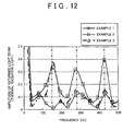
- FIG. 12 is a view illustrating a relationship between frequency and amplitude in the returned light beams of the inspection samples according to Examples 1 to 3;
- FIG. 13 is a view illustrating other examples of the relationship between frequency and amplitude in the returned light beams of the inspection samples according to Examples 1 to 3.
- Embodiment 1 of the welded portion inspection apparatus of the present invention With reference to FIGS. 1 to 3 .
- FIG. 1 is an overall configuration diagram schematically illustrating an overall configuration of Embodiment 1 of the welded portion inspection apparatus of the present invention.
- FIG. 2 is a top view to describe a form of radiation of a welding laser beam from a welding radiation portion of the inspection apparatus as illustrated in FIG. 1
- FIG. 3 is a top view to describe a form of radiation of an inspection laser beam from an inspection radiation portion of the inspection apparatus.
- An inspection apparatus 100 illustrated in FIG. 1 is mainly constituted by a welding radiation portion 1 , an inspection radiation portion 5 , a light-receiving portion 2 , a conversion portion 3 , an amplifier 4 , an inspection portion 6 , and a CRT (Cathode Ray Tube) 7 .
- the welding radiation portion 1 radiates a welding laser beam (e.g., a YAG laser having a predetermined laser wavelength) L 1 to the two workpieces W 1 , W 2 . More specifically, as illustrated in FIG. 2 , the welding radiation portion 1 rotates a focal point F 1 of the welding laser beam L 1 several times along a generally round-shaped welding locus C 11 having a radius R 11 set in the workpiece W 1 , so as to radiate the welding laser beam L 1 several times on the welding locus C 11 .
- a welding laser beam e.g., a YAG laser having a predetermined laser wavelength
- the welding radiation portion 1 moves the focal point F 1 of the welding laser beam L 1 inside the welding locus C 11 , and rotates the focal point F 1 of the welding laser beam L 1 several times along a generally round-shaped welding locus C 12 which has a radius R 12 that is smaller than the radius R 11 and which is coaxial to the welding locus C 11 , so as to radiate the welding laser beam L 1 several times on the welding locus C 12 .
- a generally round-shaped welded portion is formed in the workpieces W 1 , W 2 , thereby joining the workpieces W 1 , W 2 by welding (also referred to as Laser Screw Welding).
- a center C 0 of the welding locus C 11 or the welding locus C 12 is a welding center of the welded portion formed in the workpieces W 1 , W 2 .
- a molten pool Y 1 where the workpieces W 1 , W 2 are molten is formed on right and left sides of the welding laser beam L 1 and behind the welding laser beam L 1 in a traveling direction of the welding laser beam L 1 .
- the welding laser beam L 1 is radiated along the generally round-shaped welding loci C 1 , C 2 as described above, a generally round-shaped molten pool Y 1 is formed in the workpieces W 1 , W 2 .
- the inspection radiation portion 5 radiates an inspection laser beam L 5 to the molten pool Y 1 in a molten state via an optical system 8 and the light-receiving portion 2 . More specifically, as illustrated in FIG. 3 , the inspection radiation portion 5 rotates a focal point F 5 of the inspection laser beam L 5 several times at a generally constant speed along a generally round-shaped scanning locus C 51 having a radius R 51 set inside an outer edge of the molten pool Y 1 , so as to radiate the inspection laser beam L 5 several times on the scanning locus C 51 .
- the inspection radiation portion 5 moves the focal point F 5 of the inspection laser beam L 5 inside the scanning locus C 51 , and rotates the focal point F 5 of the inspection laser beam L 5 several times along a generally round-shaped scanning locus C 52 which has a radius R 52 that is smaller than the radius R 51 and which is coaxial to the scanning locus C 51 , so as to radiate the inspection laser beam L 5 several times on the scanning locus C 52 .
- the inspection radiation portion 5 radiates the inspection laser beam L 5 to a whole of the generally round-shaped molten pool Y 1 formed in the workpieces W 1 , W 2 .
- a center of the scanning loci C 51 , C 52 is set to the aforementioned center C 0 of the welding loci C 11 , C 12 , for example.
- the light-receiving portion 2 receives a returned light beam L 2 including reflection light of the inspection laser light L 5 which is reflected from the molten pool Y 1 of the workpieces W 1 , W 2 , vapor light (plasma light) caused due to melting and evaporation of the workpieces W 1 , W 2 , thermal radiation light (infrared light) emitted from the molten pool Y 1 of the workpieces W 1 , W 2 , and the like.
- a returned light beam L 2 including reflection light of the inspection laser light L 5 which is reflected from the molten pool Y 1 of the workpieces W 1 , W 2 , vapor light (plasma light) caused due to melting and evaporation of the workpieces W 1 , W 2 , thermal radiation light (infrared light) emitted from the molten pool Y 1 of the workpieces W 1 , W 2 , and the like.
- the conversion portion 3 converts, into an electrical signal, the returned light beam L 2 received by the light-receiving portion 2 and condensed via the optical system 8 and a condenser lens 9 , and outputs the electrical signal to the amplifier 4 .
- the amplifier 4 amplifies a signal intensity of the electrical signal output from the conversion portion 3 , and transmits it to the inspection portion 6 .
- the inspection portion 6 performs signal processing on the electrical signal transmitted from the amplifier 4 , and inspects a welding state of the welded portion formed in the workpieces W 1 , W 2 . More specifically, when the inspection laser beam L 5 is radiated to the molten pool Y 1 from the inspection radiation portion 5 several times along the scanning loci C 51 , C 52 , the inspection portion 6 detects an intensity change of the returned light beam L 2 received by the light-receiving portion 2 . Then, the inspection portion 6 inspects the welding state of the welded portion formed in the workpieces W 1 , W 2 based on a periodicity of the intensity change. Further, the inspection portion 6 transmits, to the CRT 7 , a signal processing result on the electrical signal transmitted from the amplifier 4 . The CRT 7 displays the signal processing result transmitted from the inspection portion 6 .
- Embodiment 1 of a welded portion inspection method of the present invention by use of the welded portion inspection apparatus 100 illustrated in FIG. 1 , with reference to FIGS. 4 to 7 .
- FIG. 4 is a view illustrating, in time series, an example of that intensity of the returned light beam which is transmitted to the inspection portion 6 of the inspection apparatus 100 illustrated in FIG. 1 .
- FIG. 5A is a top view to describe a relationship between the molten pool and the focal point of the inspection laser beam in a case where the welding state of the welded portion is normal
- FIG. 5B is a view taken along an arrow VB-VB of FIG. 5A
- FIG. 6A is a top view to describe a relationship between the molten pool and the focal point of the inspection laser beam in a case where the welding state of the welded portion is poor
- FIG. 6B is a view taken along an arrow VIB-VIB of FIG. 6A .
- FIG. 7 is a view illustrating an example of a relationship between frequency and amplitude of the returned light beam on which the signal processing is performed by the inspection portion 6 .
- the intensity of the returned light beam L 2 received by the light-receiving portion 2 and transmitted to the inspection portion 6 via the conversion portion 3 and the amplifier 4 changes in part of one scanning period (e.g., a period during which the inspection laser beam L 5 goes around a scanning period C 5 once) of the inspection laser beam L 5 , and periodically changes every scanning period of the inspection laser beam L 5 .
- the inspection method of Embodiment 1 such a periodicity of the intensity change of the returned light beam L 2 is detected by the inspection portion 6 .
- the inspection laser beam L 5 is radiated to the molten pool Y 1 along the generally round-shaped scanning loci C 51 , C 52 .
- Fourier transform is performed on the intensity (see FIG. 4 ) of the returned light beam L 2 transmitted to the inspection portion 6 .
- an amplitude peak is not detected at a specific frequency (see a broken line in FIG. 7 )
- amplitude peaks are detected at specific frequencies (three frequencies in FIG. 7 ) (see a continuous line in FIG. 7 ).
- By performing Fourier transform on the intensity of the returned light beam L 2 it is possible to easily detect that intensity change of the returned light beam which is caused due to a poor welding state of the welded portion. This makes it possible to more minutely inspect whether or not poor welding occurs in the welded portion formed in the workpieces W 1 , W 2 .
- a liquid level of the molten pool Y 1 formed in the workpieces W 1 , W 2 by radiation of the welding laser beam L 1 vibrates periodically, and it is found by the inventor(s) of the present invention that even in a case where the welding state of the welded portion is normal, the intensity of the returned light beam L 2 changes periodically. That is, it is considered that one of the frequencies at which the amplitude peaks are detected in FIG. 7 is a unique frequency to the intensity change of the returned light beam L 2 which unique frequency is obtained when the welding state of the welded portion is normal.
- a scanning speed of the inspection laser beam L 5 is adjusted, for example, so that the scanning period (e.g., a period during which the inspection laser beam L 5 goes around the scanning locus C 51 or the scanning locus C 52 once) of the inspection laser beam L 5 accords with a unique period of the intensity change of the returned light beam L 2 .
- This allows that intensity change of the returned light beam L 2 transmitted to the inspection portion 6 which is obtained when the welding state of the welded portion is normal, to be in a form of a generally sine curve (a dotted line in FIG. 4 ).
- the inspection laser beam L 5 is radiated along the scanning loci C 51 , C 52 set in the molten pool Y 1 formed by radiation of the welding laser beam L 1 . Then, the welding state of the welded portion is inspected based on the intensity change of the returned light beam L 2 received by the light-receiving portion 2 at the time when the inspection laser beam L 5 is radiated along the scanning loci C 51 , C 52 .
- Embodiment 2 of the welded portion inspection apparatus of the present invention With reference to FIG. 8 .
- FIG. 8 is an overall configuration diagram schematically illustrating an overall configuration of Embodiment 2 of the welded portion inspection apparatus of the present invention.
- An inspection apparatus 100 A of Embodiment 2 as illustrated in FIG. 8 is different from the inspection apparatus 100 of Embodiment 1 as illustrated in FIG. 1 in that a welding state of a welded portion is inspected by use of reflection light of a welding laser beam radiated from a welding radiation portion.
- the other configuration is generally the same as the inspection apparatus 100 of Embodiment 1. Accordingly, constituents similar to those in Embodiment 1 have the same reference signs as those in Embodiment 1 and detailed descriptions thereof are omitted.
- the inspection apparatus 100 A illustrated in the figure is mainly constituted by a welding radiation portion 1 A, a light-receiving portion 2 A, a conversion portion 3 A, an amplifier 4 A, an inspection portion 6 A, and a CRT 7 A.
- the welding radiation portion 1 A radiates a welding laser beam L 1 A to the two workpieces W 1 , W 2 via an optical system 8 A and the light-receiving portion 2 A.
- a molten pool Y 1 where the workpieces W 1 , W 2 are molten is formed on right and left sides of the welding laser beam L 1 A and behind the welding laser beam L 1 A in a traveling direction of the welding laser beam L 1 A.
- the light-receiving portion 2 A receives a returned light beam L 2 A including reflection light of the welding laser light L 1 A radiated from the welding radiation portion 1 A, the reflection light being reflected from the molten pool Y 1 of the workpieces W 1 , W 2 , vapor light (plasma light) caused due to melting and evaporation of the workpieces W 1 , W 2 , thermal radiation light (infrared light) emitted from the molten pool Y 1 of the workpieces W 1 , W 2 , and the like.
- the conversion portion 3 A converts, into an electrical signal, the returned light beam L 2 A received by the light-receiving portion 2 A and condensed via the optical system 8 A and a condenser lens 9 A, and outputs the electrical signal to the amplifier 4 A.
- the amplifier 4 A amplifies a signal intensity of the electrical signal output from the conversion portion 3 A, and transmits it to the inspection portion 6 A.
- the inspection portion 6 A performs signal processing on the electrical signal transmitted from the amplifier 4 A, and inspects a welding state of the welded portion formed in the workpieces W 1 , W 2 . More specifically, the inspection portion 6 A detects an intensity change of the returned light beam L 2 A received by the light-receiving portion 2 A at the time when the welding laser beam L 1 A is radiated from the welding radiation portion 1 A along a welding locus. Then, the inspection portion 6 A inspects the welding state of the welded portion formed in the workpieces W 1 , W 2 based on a periodicity of the intensity change. Further, the inspection portion 6 A transmits, to the CRT 7 A, a signal processing result on the electrical signal transmitted from the amplifier 4 A. The CRT 7 A displays the signal processing result transmitted from the inspection portion 6 A.
- Embodiment 2 in a case where the welding state of the welded portion is normal, the intensity change of the returned light beam L 2 A received by the light-receiving portion 2 A at the time when the welding laser beam L 1 A is radiated along the welding locus is relatively small, and in a case where the welding state of the welded portion is poor, the intensity change is relatively large. According to Embodiment 2, such a periodicity of the intensity change of the returned light beam L 2 A is detected by the inspection portion 6 A.
- the welding laser beam L 1 A is radiated along the welding locus at that unique period of the intensity change of the returned light beam L 2 A which is obtained when the welding state of the welded portion of the workpieces W 1 , W 2 is normal. Accordingly, it is possible to specify that unique frequency of the intensity change of the returned light beam L 2 A which is obtained when the welding state of the welded portion is normal, from specific frequencies at which amplitude peaks are detected by performing Fourier transform on the intensity of the returned light beam L 2 A, thereby making it possible to extract only a frequency caused due to a poor welding state of the welded portion, for example.
- Embodiment 1 described above deals with an embodiment in which the center of the scanning locus of the inspection laser beam is set to the center of the welding locus of the welding laser beam. However, it is possible to set the center of the scanning locus of the inspection laser beam to an appropriate position in the molten pool formed by radiation of the welding laser beam.
- the embodiments described above deal with an embodiment in which the welding locus of the welding laser beam and the scanning locus of the inspection laser beam have a generally round shape.
- the welding locus of the welding laser beam and the scanning locus of the inspection laser beam may have a closed loop shape such as an elliptical shape or a polygonal shape, a curved or linear shape having a predetermined length, or the like.
- the welding locus of the welding laser beam and the scanning locus of the inspection laser beam be set to pass through that part.
- the above embodiments deal with an embodiment in which the welding laser beam and the inspection laser beam are radiated to workpieces fixed to a predetermined position.
- focal positions of the welding laser beam and the inspection laser beam may be fixed and laser beam welding may be performed on the workpieces while the workpieces are being moved appropriately.
- laser beam welding may be performed on the workpieces such that the workpieces and the focal positions of the welding laser beam and the inspection laser beam are moved relative to each other.
- the inventor(s) of the present invention manufactured three types of inspection samples (Examples 1 to 3) having different welding states, and performed intensity measurement of a returned light beam from each of the inspection samples so as to evaluate a relationship between an intensity change of the returned light beam and a welding state of a welded portion thereof.
- the following generally describes a manufacturing method of an inspection sample and a measurement method of an intensity of a returned light beam from an inspection sample.
- Two workpieces each made from SCGA440 having a thickness of 0.7 mm were put on top of one another, and a welding laser beam (with an output of 1000 W and at a scanning speed of 80 m/min) was radiated several times to the workpieces along a generally round-shaped welding locus so as to form a generally round-shaped welded portion having a radius of about 2.2 mm.
- an inspection laser beam (with an output of 1000 W and at a scanning speed of 80 m/min) was radiated to go around six times along a generally round-shaped scanning locus having a radius of about 1.5 mm so as to pass through a molten pool formed in the workpieces by radiation of the welding laser beam. Then, a focal point of the inspection laser beam was moved only by about 0.5 mm, and the inspection laser beam was radiated to go around ten times along a generally round-shaped scanning locus having a radius of about 1.0 mm.
- a returned light beam including reflection light of the welding laser beam which was reflected from the molten pool of the workpieces, vapor light caused due to melting and evaporation of the workpieces, thermal radiation light emitted from the molten pool of the workpieces, and the like was received, and a returned light beam including reflection light of the inspection laser light which was reflected from the molten pool of the workpieces, vapor light, thermal radiation light, and the like was received.
- the returned light beam thus received was converted into an electrical signal, and a signal intensity thereof was measured. Note that, in the returned light beam, particularly a signal intensity of the vapor light (plasma light) caused due to melting and evaporation of the workpieces was measured in this experiment.
- FIG. 9A is a top view enlarging and illustrating a welded portion of the inspection sample according to Example 1
- FIG. 9B is a view taken along an arrow IXB-IXB in FIG. 9A
- FIG. 9C is a view illustrating an intensity of a returned light beam in the inspection sample according to Example 1 in time series.
- FIG. 10A is a top view enlarging and illustrating a welded portion of the inspection sample according to Example 2
- FIG. 10B is a view taken along an arrow XB-XB in FIG. 10A
- FIG. 10C is a view illustrating an intensity of a returned light beam in the inspection sample according to Example 2 in time series.
- FIG. 10A is a top view enlarging and illustrating a welded portion of the inspection sample according to Example 1
- FIG. 10A is a top view enlarging and illustrating a welded portion of the inspection sample according to Example 2
- FIG. 10C is a view
- FIG. 11A is a top view enlarging and illustrating a welded portion of the inspection sample according to Example 3
- FIG. 11B is a view taken along an arrow XIB-XIB in FIG. 11A
- FIG. 11C is a view illustrating an intensity of a returned light beam of the inspection sample according to Example 3 in time series.
- FIG. 12 is a view illustrating a relationship between frequency and amplitude at the time when fast Fourier transform was performed on an intensity of the returned light beam measured in the zone R 2 (about 0.41 to about 0.46 sec) in which the inspection laser beam was radiated to the inspection sample according to each of Examples 1 to 3.
- Example 12 in the inspection sample of Example 1 (the welding state is normal), a large amplitude peak was not found. However, in the inspection sample of Example 2 (holed weld), large amplitude peaks were found at frequencies of integral multiples of about 141 Hz, and in the inspection sample of Example 3 (one-piece depressed weld), a large amplitude peak was found at a frequency of about 141 Hz.
- the frequency (about 141 Hz) at which the amplitude peaks were found in the inspection samples of Examples 2 and 3 generally corresponds to a scanning frequency (1/(1.5 mm ⁇ 2 ⁇ 3.14/(80000 mm/60 sec)) Hz) of an inspection laser beam of a scanning speed of 80 m/min at the time when the inspection laser beam was radiated along the scanning locus having a radius of about 1.5 mm.
- a liquid level of a molten pool formed in the workpieces by radiation of the welding laser beam vibrates periodically, and even in a case where the welding state of the welded portion is normal, the intensities of the returned light beams measured in the zone R 1 in which the welding laser beam is radiated and in the zones R 2 , R 3 in which the inspection laser beam is radiated periodically change.
- the inventor(s) of the present invention calculated an unique frequency of the molten pool based on a surface tension and a density of the workpieces in a molten state, a magnitude and a thickness of the molten pool formed in the workpieces, etc.
- the scanning speed of the inspection laser beam was adjusted so that the scanning period of the inspection laser beam accorded with an unique period of the intensity changes of the returned light beams which is calculated from the unique frequency of the molten pool, and the inspection laser beam was radiated to the workpieces.
- FIG. 13 is a view illustrating a relationship between frequency and amplitude at the time when the inspection laser beam was radiated to the molten pool in Example 1 (the welding state is normal) at the unique period of the intensity change of the returned light beam and fast Fourier transform was performed on the intensity of the returned light beam (particularly, thermal radiation light emitted from the molten pool of the workpieces) measured in the zone R 2 .
Landscapes
- Physics & Mathematics (AREA)
- Engineering & Computer Science (AREA)
- Optics & Photonics (AREA)
- Mechanical Engineering (AREA)
- Plasma & Fusion (AREA)
- Health & Medical Sciences (AREA)
- Life Sciences & Earth Sciences (AREA)
- Chemical & Material Sciences (AREA)
- General Health & Medical Sciences (AREA)
- Analytical Chemistry (AREA)
- Biochemistry (AREA)
- General Physics & Mathematics (AREA)
- Immunology (AREA)
- Pathology (AREA)
- Medicinal Chemistry (AREA)
- Food Science & Technology (AREA)
- Laser Beam Processing (AREA)
- Investigating Materials By The Use Of Optical Means Adapted For Particular Applications (AREA)
- Quality & Reliability (AREA)
Applications Claiming Priority (3)
| Application Number | Priority Date | Filing Date | Title |
|---|---|---|---|
| JP2013-073202 | 2013-03-29 | ||
| JP2013073202A JP5947740B2 (ja) | 2013-03-29 | 2013-03-29 | 溶接部の検査装置とその検査方法 |
| PCT/IB2014/000451 WO2014155191A2 (en) | 2013-03-29 | 2014-03-28 | Welded portion inspection apparatus and inspection method thereof |
Publications (2)
| Publication Number | Publication Date |
|---|---|
| US20160061727A1 US20160061727A1 (en) | 2016-03-03 |
| US9506862B2 true US9506862B2 (en) | 2016-11-29 |
Family
ID=50489352
Family Applications (1)
| Application Number | Title | Priority Date | Filing Date |
|---|---|---|---|
| US14/780,584 Active US9506862B2 (en) | 2013-03-29 | 2014-03-28 | Welded portion inspection apparatus and inspection method thereof |
Country Status (13)
| Country | Link |
|---|---|
| US (1) | US9506862B2 (enExample) |
| EP (1) | EP2978560B1 (enExample) |
| JP (1) | JP5947740B2 (enExample) |
| KR (1) | KR101731750B1 (enExample) |
| CN (1) | CN105102173B (enExample) |
| BR (1) | BR112015024617A2 (enExample) |
| CA (1) | CA2908424C (enExample) |
| ES (1) | ES2727634T3 (enExample) |
| MX (1) | MX347097B (enExample) |
| RU (1) | RU2635588C2 (enExample) |
| TR (1) | TR201907253T4 (enExample) |
| WO (1) | WO2014155191A2 (enExample) |
| ZA (1) | ZA201507198B (enExample) |
Cited By (3)
| Publication number | Priority date | Publication date | Assignee | Title |
|---|---|---|---|---|
| US11229973B2 (en) | 2016-03-18 | 2022-01-25 | Trumpf Laser- Und Systemtechnik Gmbh | Detection of hot cracks in laser welding |
| US20220276135A1 (en) * | 2021-03-01 | 2022-09-01 | Saudi Arabian Oil Company | Method of testing longitudinal submerged arc welded pipe susceptibility through-thickness hydrogen cracking |
| US20240293897A1 (en) * | 2018-06-05 | 2024-09-05 | Electro Scientific Industries, Inc. | Laser-processing apparatus, methods of operating the same, and methods of processing workpieces using the same |
Families Citing this family (27)
| Publication number | Priority date | Publication date | Assignee | Title |
|---|---|---|---|---|
| JP5947741B2 (ja) | 2013-03-29 | 2016-07-06 | トヨタ自動車株式会社 | 溶接部の検査装置とその検査方法 |
| JP5842851B2 (ja) | 2013-03-29 | 2016-01-13 | トヨタ自動車株式会社 | 溶接部の検査装置とその検査方法 |
| JP5849985B2 (ja) | 2013-04-15 | 2016-02-03 | トヨタ自動車株式会社 | 溶接部の検査装置とその検査方法 |
| CN108463716A (zh) * | 2016-01-14 | 2018-08-28 | 日产自动车株式会社 | 激光焊接部的孔检测方法以及激光焊接装置 |
| CN105458459B (zh) * | 2016-01-15 | 2017-05-17 | 兰州理工大学 | 一种检测脉冲钨极氩弧焊熔池振荡频率的方法及装置 |
| JP6885088B2 (ja) * | 2016-02-29 | 2021-06-09 | 日本製鉄株式会社 | 溶接継手を有する鋼部材及びその製造方法 |
| JP6500831B2 (ja) * | 2016-05-11 | 2019-04-17 | トヨタ自動車株式会社 | 溶接判定装置 |
| JP6729192B2 (ja) * | 2016-08-31 | 2020-07-22 | 日本製鉄株式会社 | 溶接継手及びその製造方法 |
| JP6524992B2 (ja) * | 2016-12-22 | 2019-06-05 | トヨタ自動車株式会社 | レーザ溶接方法およびレーザ溶接装置 |
| US20200114469A1 (en) * | 2017-02-09 | 2020-04-16 | GM Global Technology Operations LLC | Method for laser welding light metal workpieces that include a surface oxide coating |
| JP6579400B2 (ja) * | 2017-10-26 | 2019-09-25 | パナソニックIpマネジメント株式会社 | レーザ溶接装置及びレーザ溶接方法 |
| JP7063083B2 (ja) * | 2018-04-25 | 2022-05-09 | トヨタ自動車株式会社 | レーザ溶接方法 |
| US11400544B2 (en) | 2018-06-08 | 2022-08-02 | Hewlett-Packard Development Company, L.P. | Selective laser melting (SLM) additive manufacturing |
| JP7121911B2 (ja) * | 2019-01-29 | 2022-08-19 | トヨタ自動車株式会社 | 溶接品質検査方法および溶接品質検査装置 |
| CN110095416B (zh) * | 2019-04-29 | 2021-10-08 | 西北核技术研究所 | 一种金属熔池激光吸收率分布在线测量系统和方法 |
| JP6835151B2 (ja) * | 2019-06-28 | 2021-02-24 | 株式会社安川電機 | 評価装置、評価方法、評価システムおよび評価プログラム |
| JP7445879B2 (ja) * | 2019-08-06 | 2024-03-08 | パナソニックIpマネジメント株式会社 | デュアル波長レーザシステム及びそのシステムを用いた材料加工 |
| JP6751902B2 (ja) * | 2019-08-14 | 2020-09-09 | パナソニックIpマネジメント株式会社 | レーザ溶接装置及びレーザ溶接方法 |
| KR102235761B1 (ko) * | 2019-12-31 | 2021-04-02 | 한국과학기술원 | 3d 프린팅 공정의 펨토초 레이저 기반 초음파 계측 장치 및 이를 구비한 3d 프린팅 시스템 |
| CN111380872B (zh) * | 2020-03-18 | 2022-12-09 | 深圳科瑞技术股份有限公司 | 终端中框的等距轨迹规划方法、系统及控制器 |
| WO2022004610A1 (ja) * | 2020-06-29 | 2022-01-06 | パナソニックIpマネジメント株式会社 | レーザ溶接装置およびレーザ溶接方法 |
| JP7539084B2 (ja) * | 2020-11-24 | 2024-08-23 | パナソニックIpマネジメント株式会社 | レーザ加工システム及び治具 |
| JP7542422B2 (ja) * | 2020-12-11 | 2024-08-30 | 株式会社東芝 | 溶接状態の検出方法、および溶接装置 |
| WO2022181061A1 (ja) * | 2021-02-25 | 2022-09-01 | パナソニックIpマネジメント株式会社 | 推定モデル生成装置および加工状態推定装置 |
| DE102021122892A1 (de) * | 2021-09-03 | 2023-03-09 | Te Connectivity Germany Gmbh | Mit einem Fenster zum Laserschweißen versehenes Halbfabrikat zur Herstellung eines elektrischen Kontaktelements sowie Verfahren zur Herstellung eines elektrischen Kontaktelements und elektrisches Kontaktelement |
| JP7540449B2 (ja) * | 2022-02-10 | 2024-08-27 | トヨタ自動車株式会社 | スポット溶接打痕の中心座標の検出方法、レーザー溶接方法、および接合方法 |
| JP7843458B2 (ja) * | 2022-05-17 | 2026-04-10 | パナソニックIpマネジメント株式会社 | レーザ出力評価方法及びレーザ出力評価装置 |
Citations (10)
| Publication number | Priority date | Publication date | Assignee | Title |
|---|---|---|---|---|
| US4572941A (en) | 1983-06-27 | 1986-02-25 | Sciaky, S.A. | Method of and installation for spot-welding by laser beam |
| US5155329A (en) * | 1990-01-08 | 1992-10-13 | Mitsubishi Jukogyo Kabushiki Kaisha | Monitoring method and system for laser beam welding |
| US5651903A (en) | 1995-10-12 | 1997-07-29 | Trw Inc. | Method and apparatus for evaluating laser welding |
| US20020158053A1 (en) | 2001-04-25 | 2002-10-31 | Berthold Kessler | Method and sensor device for monitoring a laser machining operation to be performed on a work piece as well as laser machining head with a sensor device of the kind |
| US6937329B2 (en) | 2000-07-06 | 2005-08-30 | Aerospatiale Matra Ccr | Method for detecting and identifying defects in a laser beam weld seam |
| JP2008087056A (ja) | 2006-10-03 | 2008-04-17 | Toyota Motor Corp | レーザ溶接品質判定システムおよび品質判定方法 |
| JP2008272767A (ja) | 2007-04-26 | 2008-11-13 | Kanto Auto Works Ltd | レーザ溶接装置及びレーザ溶接の品質管理方法 |
| US20110215074A1 (en) * | 2008-11-27 | 2011-09-08 | Panasonic Corporation | Hybrid welding method and hybrid welding apparatus |
| US8506872B2 (en) * | 2009-05-29 | 2013-08-13 | Stanley Electric Co., Ltd. | Method for manufacturing resin mold assembly |
| WO2014155190A2 (en) | 2013-03-29 | 2014-10-02 | Toyota Jidosha Kabushiki Kaisha | Welded portion inspection apparatus and inspection method thereof |
Family Cites Families (14)
| Publication number | Priority date | Publication date | Assignee | Title |
|---|---|---|---|---|
| US5681490A (en) * | 1995-09-18 | 1997-10-28 | Chang; Dale U. | Laser weld quality monitoring system |
| RU2155653C2 (ru) * | 1998-06-08 | 2000-09-10 | Курский государственный технический университет | Видеосенсорное устройство |
| DE19852302A1 (de) * | 1998-11-12 | 2000-05-25 | Fraunhofer Ges Forschung | Verfahren und Vorrichtung zum Bearbeiten von Werkstücken mit Hochenergiestrahlung |
| JP3154177B2 (ja) | 1998-11-19 | 2001-04-09 | 住友重機械工業株式会社 | レーザ溶接の溶接状態判定方法および溶接状態判定装置 |
| DE19957163C1 (de) * | 1999-11-27 | 2001-08-09 | Thyssenkrupp Stahl Ag | Verfahren und Vorrichtung zur Qualitätskontrolle der Naht an mit einem Laser stumpf geschweißten Blechen oder Bändern |
| DE10103255B4 (de) * | 2001-01-25 | 2004-12-30 | Robert Bosch Gmbh | Verfahren zur automatischen Beurteilung von Laserbearbeitungsprozessen |
| EP2355270A3 (en) * | 2001-10-16 | 2012-05-09 | Kataoka Corporation | Pulse oscillating type solid laser unit and laser process unit |
| SE521787C2 (sv) * | 2002-04-05 | 2003-12-09 | Volvo Aero Corp | Anordning och förfarande för kontroll av ett svetsområde, inrättning och förfarande för styrning av en svetsoperation, datorprogram och datorprogramprodukt |
| JP4026404B2 (ja) * | 2002-05-02 | 2007-12-26 | 日産自動車株式会社 | レーザー溶接部の品質モニタリング方法およびその装置 |
| JP4688423B2 (ja) | 2004-02-27 | 2011-05-25 | 独立行政法人物質・材料研究機構 | レーザ溶接方法 |
| JP2007098464A (ja) * | 2005-10-07 | 2007-04-19 | Nissan Motor Co Ltd | レーザー加工ロボット制御装置、レーザー加工ロボット制御方法およびレーザー加工ロボット制御プログラム |
| JP4818029B2 (ja) | 2006-08-29 | 2011-11-16 | 東急車輛製造株式会社 | レーザ溶接評価方法 |
| JP5609595B2 (ja) * | 2010-12-01 | 2014-10-22 | トヨタ自動車株式会社 | レーザ溶接方法 |
| JP5902400B2 (ja) * | 2011-04-26 | 2016-04-13 | トヨタ自動車株式会社 | レーザ溶接装置、レーザ溶接方法、鋼板積層体の製造方法及び積層体のレーザ溶接による溶接構造 |
-
2013
- 2013-03-29 JP JP2013073202A patent/JP5947740B2/ja not_active Expired - Fee Related
-
2014
- 2014-03-28 US US14/780,584 patent/US9506862B2/en active Active
- 2014-03-28 EP EP14717863.6A patent/EP2978560B1/en active Active
- 2014-03-28 TR TR2019/07253T patent/TR201907253T4/tr unknown
- 2014-03-28 CA CA2908424A patent/CA2908424C/en not_active Expired - Fee Related
- 2014-03-28 CN CN201480018967.0A patent/CN105102173B/zh active Active
- 2014-03-28 KR KR1020157026788A patent/KR101731750B1/ko not_active Expired - Fee Related
- 2014-03-28 RU RU2015140714A patent/RU2635588C2/ru not_active IP Right Cessation
- 2014-03-28 WO PCT/IB2014/000451 patent/WO2014155191A2/en not_active Ceased
- 2014-03-28 BR BR112015024617A patent/BR112015024617A2/pt not_active Application Discontinuation
- 2014-03-28 ES ES14717863T patent/ES2727634T3/es active Active
- 2014-03-28 MX MX2015013690A patent/MX347097B/es active IP Right Grant
-
2015
- 2015-09-29 ZA ZA2015/07198A patent/ZA201507198B/en unknown
Patent Citations (12)
| Publication number | Priority date | Publication date | Assignee | Title |
|---|---|---|---|---|
| US4572941A (en) | 1983-06-27 | 1986-02-25 | Sciaky, S.A. | Method of and installation for spot-welding by laser beam |
| JPH0380596B2 (enExample) | 1983-06-27 | 1991-12-25 | Shiakii Sa | |
| US5155329A (en) * | 1990-01-08 | 1992-10-13 | Mitsubishi Jukogyo Kabushiki Kaisha | Monitoring method and system for laser beam welding |
| US5651903A (en) | 1995-10-12 | 1997-07-29 | Trw Inc. | Method and apparatus for evaluating laser welding |
| US6937329B2 (en) | 2000-07-06 | 2005-08-30 | Aerospatiale Matra Ccr | Method for detecting and identifying defects in a laser beam weld seam |
| US20020158053A1 (en) | 2001-04-25 | 2002-10-31 | Berthold Kessler | Method and sensor device for monitoring a laser machining operation to be performed on a work piece as well as laser machining head with a sensor device of the kind |
| JP2008087056A (ja) | 2006-10-03 | 2008-04-17 | Toyota Motor Corp | レーザ溶接品質判定システムおよび品質判定方法 |
| JP2008272767A (ja) | 2007-04-26 | 2008-11-13 | Kanto Auto Works Ltd | レーザ溶接装置及びレーザ溶接の品質管理方法 |
| US20110215074A1 (en) * | 2008-11-27 | 2011-09-08 | Panasonic Corporation | Hybrid welding method and hybrid welding apparatus |
| US8506872B2 (en) * | 2009-05-29 | 2013-08-13 | Stanley Electric Co., Ltd. | Method for manufacturing resin mold assembly |
| WO2014155190A2 (en) | 2013-03-29 | 2014-10-02 | Toyota Jidosha Kabushiki Kaisha | Welded portion inspection apparatus and inspection method thereof |
| JP2014198345A (ja) | 2013-03-29 | 2014-10-23 | トヨタ自動車株式会社 | 溶接部の検査装置とその検査方法 |
Cited By (4)
| Publication number | Priority date | Publication date | Assignee | Title |
|---|---|---|---|---|
| US11229973B2 (en) | 2016-03-18 | 2022-01-25 | Trumpf Laser- Und Systemtechnik Gmbh | Detection of hot cracks in laser welding |
| US20240293897A1 (en) * | 2018-06-05 | 2024-09-05 | Electro Scientific Industries, Inc. | Laser-processing apparatus, methods of operating the same, and methods of processing workpieces using the same |
| US20220276135A1 (en) * | 2021-03-01 | 2022-09-01 | Saudi Arabian Oil Company | Method of testing longitudinal submerged arc welded pipe susceptibility through-thickness hydrogen cracking |
| US11747241B2 (en) * | 2021-03-01 | 2023-09-05 | Saudi Arabian Oil Company | Method of testing longitudinal submerged arc welded pipe susceptibility through-thickness hydrogen cracking |
Also Published As
| Publication number | Publication date |
|---|---|
| EP2978560A2 (en) | 2016-02-03 |
| CN105102173A (zh) | 2015-11-25 |
| KR101731750B1 (ko) | 2017-04-28 |
| MX347097B (es) | 2017-04-12 |
| JP2014195822A (ja) | 2014-10-16 |
| RU2015140714A (ru) | 2017-05-05 |
| WO2014155191A3 (en) | 2014-12-04 |
| EP2978560B1 (en) | 2019-04-24 |
| WO2014155191A2 (en) | 2014-10-02 |
| US20160061727A1 (en) | 2016-03-03 |
| KR20150119961A (ko) | 2015-10-26 |
| ES2727634T3 (es) | 2019-10-17 |
| RU2635588C2 (ru) | 2017-11-14 |
| CA2908424A1 (en) | 2014-10-02 |
| WO2014155191A8 (en) | 2015-07-23 |
| TR201907253T4 (tr) | 2019-06-21 |
| BR112015024617A2 (pt) | 2017-07-18 |
| CA2908424C (en) | 2017-06-20 |
| JP5947740B2 (ja) | 2016-07-06 |
| MX2015013690A (es) | 2016-02-26 |
| ZA201507198B (en) | 2016-12-21 |
| CN105102173B (zh) | 2016-11-30 |
Similar Documents
| Publication | Publication Date | Title |
|---|---|---|
| US9506862B2 (en) | Welded portion inspection apparatus and inspection method thereof | |
| US9517533B2 (en) | Welded portion inspection apparatus and inspection method thereof, with inspection in different zones of the molten pool | |
| US9527166B2 (en) | Welding portion inspection device and inspection method therefore, with extracting portion for extracting evaporation luminescence and thermal radiation | |
| US9452496B2 (en) | Welding portion inspection device and inspection method therefor | |
| EP2915619B1 (en) | Welded portion inspection method | |
| JP2009520984A (ja) | 鋼板溶接部オンライン検出装置及び方法 | |
| CN114535787A (zh) | 激光加工系统以及夹具 | |
| JP5472380B2 (ja) | 溶着状態検出装置および溶着状態検出方法 | |
| JP2009148795A (ja) | 溶着状態検出装置および溶着状態検出方法 |
Legal Events
| Date | Code | Title | Description |
|---|---|---|---|
| AS | Assignment |
Owner name: TOYOTA JIDOSHA KABUSHIKI KAISHA, JAPAN Free format text: ASSIGNMENT OF ASSIGNORS INTEREST;ASSIGNORS:KOBAYASHI, HIROOMI;FURUKAWA, MASASHI;UCHIDA, KEISUKE;AND OTHERS;SIGNING DATES FROM 20150630 TO 20150910;REEL/FRAME:036666/0054 |
|
| STCF | Information on status: patent grant |
Free format text: PATENTED CASE |
|
| MAFP | Maintenance fee payment |
Free format text: PAYMENT OF MAINTENANCE FEE, 4TH YEAR, LARGE ENTITY (ORIGINAL EVENT CODE: M1551); ENTITY STATUS OF PATENT OWNER: LARGE ENTITY Year of fee payment: 4 |
|
| MAFP | Maintenance fee payment |
Free format text: PAYMENT OF MAINTENANCE FEE, 8TH YEAR, LARGE ENTITY (ORIGINAL EVENT CODE: M1552); ENTITY STATUS OF PATENT OWNER: LARGE ENTITY Year of fee payment: 8 |