US9482292B2 - Piston-integrated seal - Google Patents
Piston-integrated seal Download PDFInfo
- Publication number
- US9482292B2 US9482292B2 US14/892,305 US201314892305A US9482292B2 US 9482292 B2 US9482292 B2 US 9482292B2 US 201314892305 A US201314892305 A US 201314892305A US 9482292 B2 US9482292 B2 US 9482292B2
- Authority
- US
- United States
- Prior art keywords
- hydraulic chamber
- clutch
- edge portion
- seal
- piston
- Prior art date
- Legal status (The legal status is an assumption and is not a legal conclusion. Google has not performed a legal analysis and makes no representation as to the accuracy of the status listed.)
- Active
Links
- 241001135931 Anolis Species 0.000 claims 1
- 230000002093 peripheral effect Effects 0.000 description 21
- 230000008859 change Effects 0.000 description 9
- 230000004044 response Effects 0.000 description 5
- 230000009471 action Effects 0.000 description 4
- 239000000463 material Substances 0.000 description 4
- 230000005540 biological transmission Effects 0.000 description 2
- 239000013013 elastic material Substances 0.000 description 2
- 238000005461 lubrication Methods 0.000 description 2
- 230000009467 reduction Effects 0.000 description 2
- 230000035939 shock Effects 0.000 description 2
- 229920003002 synthetic resin Polymers 0.000 description 2
- 239000000057 synthetic resin Substances 0.000 description 2
- 238000005452 bending Methods 0.000 description 1
- 238000006073 displacement reaction Methods 0.000 description 1
- 230000000694 effects Effects 0.000 description 1
- 239000000446 fuel Substances 0.000 description 1
- 230000006872 improvement Effects 0.000 description 1
- 239000002184 metal Substances 0.000 description 1
- 238000012856 packing Methods 0.000 description 1
Images


Classifications
-
- F—MECHANICAL ENGINEERING; LIGHTING; HEATING; WEAPONS; BLASTING
- F16—ENGINEERING ELEMENTS AND UNITS; GENERAL MEASURES FOR PRODUCING AND MAINTAINING EFFECTIVE FUNCTIONING OF MACHINES OR INSTALLATIONS; THERMAL INSULATION IN GENERAL
- F16D—COUPLINGS FOR TRANSMITTING ROTATION; CLUTCHES; BRAKES
- F16D25/00—Fluid-actuated clutches
- F16D25/12—Details not specific to one of the before-mentioned types
-
- F—MECHANICAL ENGINEERING; LIGHTING; HEATING; WEAPONS; BLASTING
- F16—ENGINEERING ELEMENTS AND UNITS; GENERAL MEASURES FOR PRODUCING AND MAINTAINING EFFECTIVE FUNCTIONING OF MACHINES OR INSTALLATIONS; THERMAL INSULATION IN GENERAL
- F16D—COUPLINGS FOR TRANSMITTING ROTATION; CLUTCHES; BRAKES
- F16D25/00—Fluid-actuated clutches
- F16D25/06—Fluid-actuated clutches in which the fluid actuates a piston incorporated in, i.e. rotating with the clutch
- F16D25/062—Fluid-actuated clutches in which the fluid actuates a piston incorporated in, i.e. rotating with the clutch the clutch having friction surfaces
- F16D25/063—Fluid-actuated clutches in which the fluid actuates a piston incorporated in, i.e. rotating with the clutch the clutch having friction surfaces with clutch members exclusively moving axially
- F16D25/0635—Fluid-actuated clutches in which the fluid actuates a piston incorporated in, i.e. rotating with the clutch the clutch having friction surfaces with clutch members exclusively moving axially with flat friction surfaces, e.g. discs
- F16D25/0638—Fluid-actuated clutches in which the fluid actuates a piston incorporated in, i.e. rotating with the clutch the clutch having friction surfaces with clutch members exclusively moving axially with flat friction surfaces, e.g. discs with more than two discs, e.g. multiple lamellae
-
- F—MECHANICAL ENGINEERING; LIGHTING; HEATING; WEAPONS; BLASTING
- F16—ENGINEERING ELEMENTS AND UNITS; GENERAL MEASURES FOR PRODUCING AND MAINTAINING EFFECTIVE FUNCTIONING OF MACHINES OR INSTALLATIONS; THERMAL INSULATION IN GENERAL
- F16J—PISTONS; CYLINDERS; SEALINGS
- F16J15/00—Sealings
- F16J15/16—Sealings between relatively-moving surfaces
- F16J15/32—Sealings between relatively-moving surfaces with elastic sealings, e.g. O-rings
- F16J15/3204—Sealings between relatively-moving surfaces with elastic sealings, e.g. O-rings with at least one lip
- F16J15/3232—Sealings between relatively-moving surfaces with elastic sealings, e.g. O-rings with at least one lip having two or more lips
-
- F—MECHANICAL ENGINEERING; LIGHTING; HEATING; WEAPONS; BLASTING
- F16—ENGINEERING ELEMENTS AND UNITS; GENERAL MEASURES FOR PRODUCING AND MAINTAINING EFFECTIVE FUNCTIONING OF MACHINES OR INSTALLATIONS; THERMAL INSULATION IN GENERAL
- F16D—COUPLINGS FOR TRANSMITTING ROTATION; CLUTCHES; BRAKES
- F16D2300/00—Special features for couplings or clutches
- F16D2300/08—Details or arrangements of sealings not provided for in group F16D3/84
Definitions
- the present invention relates to a piston-integrated seal which is used in a hydraulic clutch of an automatic transmission in a vehicle.
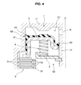
- FIG. 4 shows a hydraulic clutch which employs a conventional piston-integrated seal
- FIG. 5 shows an outline structure of the conventional piston-integrated seal.
- reference numeral 1 denotes an annular clutch cylinder which rotates together with a drive shaft (not shown)
- reference numeral 2 denotes a clutch piston which is arranged within the clutch cylinder 1 so as to be movable in an axial direction, and defines a hydraulic chamber S 1 between the clutch piston and an end plate portion 11 of the clutch cylinder 1
- reference numeral 3 denotes a spring holder which is arranged in a space S 2 in an opposite side to the hydraulic chamber S 1 as seen from the clutch piston 2 and is locked its inner diameter to an inner tube portion 13 of the clutch cylinder 1
- reference numeral 4 denotes a return spring which is interposed between the clutch piston 2 and the spring holder 3 in an appropriately compressed state
- reference numeral 5 denotes a multiple disc clutch constructed by a plurality of drive plates 51 which are locked to the clutch cylinder 1 side in a circumferential direction under a movable state in an axial direction, and a plurality of driven plates 52 which
- This kind of hydraulic clutch is structured such that the piston 2 displaces in an axial direction within the clutch cylinder 1 by applying a hydraulic pressure to the hydraulic chamber S 1 via a pressure guide port 14 which is provided in the inner tube portion 13 of the clutch cylinder 1 or releasing the hydraulic pressure, thereby friction fastening the drive plate 51 and the driven plate 52 of the multiple disc clutch 5 or canceling the friction fastening so as to carry out a clutch connection and disconnection motion.
- a packing such as an O-ring has been conventionally used as a seal means for inner and outer peripheries of the clutch piston 2 , however, the clutch piston 2 is desired to be lowered its friction in order to achieve an improvement of fuel consumption and a reduction of shift shock (a shock generated at the friction fastening time of the clutch).
- shift shock a shock generated at the friction fastening time of the clutch.
- a piston-integrated seal 100 having seal lips 101 and 101 has been a mainstream, the seal lips 101 and 101 being slidably brought into close contact with the outer tube portion 12 and the inner tube portion 13 of the clutch cylinder 1 while being directed to the hydraulic chamber S 1 side.
- the piston-integrated seal 100 is integrally formed in the clutch piston 2 by a rubber-like elastic material (a rubber material or a synthetic resin material having a rubber-like elasticity) (refer, for example, to Japanese Unexamined Patent Publication No. 2001-241467).
- a rubber-like elastic material a rubber material or a synthetic resin material having a rubber-like elasticity
- the seal lip 101 is generally structured such that an angle ⁇ of an inclined surface closer to the hydraulic chamber S 1 side than the seal edge portion where a contact pressure P (an interference L) in relation to the other sliding surface shown by a two-dot chain line in the drawing is the greatest is larger than an angle ⁇ of an inclined surface in an opposite side, and a length Ha in an axial direction from the seal edge portion to the root portion in the opposite side to the hydraulic chamber S 1 is comparatively long.
- the friction can be reduced by forming a desired number of lubrication grooves in the sliding surface of the seal lip 101 (refer, for example, to Japanese Unexamined Patent Publication No. 9-210088). However, it has been insufficient to reduce the friction difference caused by the directionality of the seal lip 101 .
- the present invention is made by taking the above points into consideration, and a technical object of the present invention is to improve a shift change response of a hydraulic clutch by reducing a difference in friction due to a sliding direction caused by a directionality of a seal lip.
- a piston-integrated seal according to the invention of a first aspect has a seal lip which is integrally provided in a clutch piston of a hydraulic clutch and is directed to a hydraulic chamber side, the seal lip is structured such that a main seal edge portion in a hydraulic chamber side and a sub seal edge portion in an anti-hydraulic chamber side are formed in a sliding portion in relation to the other sliding surface, and the main seal edge portion and the sub seal edge portion are structured such that an angle of an inclined surface in the hydraulic chamber side is smaller than an angle of an inclined surface in the anti-hydraulic chamber side in a un-installed state, and the angle of the inclined surface in the hydraulic chamber side in relation to the other sliding surface is approximately equal to the angle of the inclined surface in the anti-hydraulic chamber side in an installed state.
- a piston-integrated seal according to the invention of a second aspect is the structure described in the first aspect, wherein an interference of the sub seal edge portion is smaller than an interference of the main seal edge portion.
- a piston-integrated seal according to the invention of a third aspect is the structure described in the first or second aspect, wherein the sub seal edge portion is positioned closer to the anti-hydraulic chamber side than a surface of a base portion in the hydraulic chamber side of the seal lip.
- the contact area with the other sliding surface is smaller by forming the main seal edge portion in the hydraulic chamber side and the sub seal edge portion in the anti-hydraulic chamber side, in the sliding portion of the seal lip, the friction can be reduced.
- the angle of the inclined surface in the hydraulic chamber side in relation to the other sliding surface is approximately equal to the angle of the inclined surface in the anti-hydraulic chamber side in the installed state (the contact state with the other sliding surface), it is possible to reduce the difference between the friction at the stroking time to the hydraulic chamber side and the friction at the stroking time to the anti-hydraulic chamber side. As a result, it is possible to improve the shift change response of the hydraulic clutch.
- the interference of the sub seal edge portion is smaller than the interference of the main seal edge portion, since the deformation of the main seal edge portion can be absorbed by the sub seal edge portion, change in contact load of the main seal edge portion in relation to the other sliding surface can be suppressed regardless of change of the hydraulic pressure acting on the seal lip. As a result, it is possible to reduce the difference between the friction at the stroking time to the hydraulic chamber side and the friction at the stroking time to the anti-hydraulic chamber side.
- the sub seal edge portion is positioned closer to the anti-hydraulic chamber side than the surface of the base portion in the hydraulic chamber side of the seal lip, since the deformation of the sub seal edge portion caused by applying the hydraulic pressure is suppressed, a seal lip deformation suppressing action by the sub seal edge portion is enhanced, and it is possible to improve the pressure resistance of the seal lip.
- FIG. 1 is a one-side cross sectional view showing a preferable embodiment of a piston-integrated seal according to the present invention together with a part of a hydraulic clutch by cutting along a plane passing through an axis O;
- FIG. 2 is an explanatory view showing a substantial part of the preferable embodiment of the piston-integrated seal according to the present invention
- FIG. 3 is an explanatory view showing angles of included surface in a un-installed state and an installed state in the substantial part of the preferable embodiment of the piston-integrated seal according to the present invention
- FIG. 4 is a one-side cross sectional view showing a conventional piston-integrated seal together with a part of a hydraulic clutch by cutting along a plane passing through an axis O;
- FIG. 5 is an explanatory view showing a part of the conventional piston-integrated seal.
- FIG. 1 is a one-side cross sectional view showing the piston-integrated seal according to the embodiment together with a part of a hydraulic clutch
- reference numeral 1 denotes a clutch cylinder
- reference numeral 2 denotes a clutch piston which is arranged within the clutch cylinder 1 so as to be movable in an axial direction and defines a hydraulic chamber S 1 between the clutch piston and the clutch cylinder 1
- reference numeral 1 denotes a spring holder which is arranged in a space (hereinafter, refer to as an anti-hydraulic chamber side space) S 2 in an opposite side to the hydraulic chamber S 1 as seen from the piston 2 and is locked to an inner tube portion 13 of the clutch cylinder 1 in its inner diameter portion
- reference numeral 4 denotes a return spring which is interposed in an appropriately compressed state between the clutch piston 2 and the spring holder 3
- reference numeral 5 denotes a multiple disc
- the clutch cylinder 1 has an end plate portion 11 , and an outer tube portion 12 and an inner tube portion 13 which extend from an outer diameter and an inner diameter of the end plate portion, and is rotated around an axis O together with a drive shaft (not shown). Further, the inner tube portion 13 of the clutch cylinder 1 is provided with a pressure introduction port 14 for introducing a hydraulic pressure by an oil (ATF) to the hydraulic chamber S 1 .
- ATF oil
- the clutch piston 2 is a metal press molded product, and has a pressure receiving portion 21 which is faced to the end plate portion 11 of the clutch cylinder 1 in an axial direction, an outer tube portion 22 which extends from an outer diameter portion of the pressure receiving portion 21 to the anti-hydraulic chamber side space S 2 side and faces to the outer tube portion 12 of the clutch cylinder 1 in a radial direction, and an inner tube portion 23 which extends from an inner diameter portion of the pressure receiving portion 21 to an opposite side to the hydraulic chamber S 1 and faces to the inner tube portion 13 of the clutch cylinder 1 in a radial direction.
- a clutch pressing portion 24 is formed in a leading end portion of the outer tube portion 22 of the clutch piston 2
- an inward collar portion 25 is formed in a leading end portion of the inner tube portion 13 of the clutch piston 2 .
- the return spring 4 is structured such as to always energize the clutch piston 2 in a direction of reducing a cubic capacity of the hydraulic chamber S 1 and is constructed by a coil spring. A plurality of return springs 4 are arranged at predetermined intervals in a circumferential direction.
- the multiple disc clutch 5 is structured such that a plurality of drive plates 51 and a plurality of driven plates 52 are arranged alternately in an axial direction.
- the drive plates 51 are locked to the outer tube portion of the clutch cylinder 1 in a circumferential direction in a state in which the drive plates 51 can move in an axial direction
- the driven plates 52 are locked to a clutch hub 53 provided in a driven shaft side (not shown) in a circumferential direction in a state in which the driven shaft can move in an axial direction.
- a piston-integrated seal 6 made of a rubber-like elastic material (a rubber material or a synthetic resin material having a rubber-like elasticity) is integrally provided in the clutch piston 2 .
- the piston-integrated seal 6 has a base portion 61 which extends so as to cover an outer peripheral surface of the outer tube portion 22 , a surface in the hydraulic chamber S 1 side of the pressure receiving portion 21 , an inner peripheral surface of the inner tube portion 23 and the inward collar portion 25 in the clutch piston 2 , and seal lips 62 and 62 which are respectively positioned in the vicinity of an outer diameter portion of the pressure receiving portion 21 and an inner diameter of the inward collar portion 25 and are formed so as to extend from the base portion 61 to the hydraulic chamber S 1 side.
- the seal 62 lip in the outer peripheral side is slidably brought into close contact with the inner peripheral surface of the outer tube portion 12 in the clutch cylinder 1
- the seal lip 62 in the inner peripheral side is slidably brought into close contact with the outer peripheral surface of the inner tube portion 13 in the clutch cylinder 1 .
- a plurality of projections 63 are formed at uniform intervals in a circumferential direction in a portion which is bonded to the pressure receiving portion 21 of the clutch piston 2 , in the base portion 61 of the piston-integrated seal 6 .
- the projections 63 prevent occlusion of the hydraulic chamber S 1 by the close contact of the base portion 61 with the end plate portion 11 of the clutch cylinder 1 when the clutch piston 2 moves to its top dead center position.
- the seal lip 62 is structured, as shown in FIG. 2 in an enlarged manner, such that a main seal edge portion 62 a in the hydraulic chamber S 1 side and a sub seal edge portion 62 b in the anti-hydraulic chamber side space S 2 side are formed in a sliding portion with an inner peripheral surface of the outer tube portion 12 of the clutch cylinder 1 or an outer peripheral surface of the inner tube portion 13 .
- a protruding height of the sub seal edge portion 62 b is lower than a protruding height of the main seal edge portion 62 a .
- an interference L 2 of the sub seal edge portion 62 b is set smaller than an interference L 1 of the main seal edge portion 62 a in relation to the inner peripheral surface of the outer tube portion 12 or the outer peripheral surface of the inner tube portion 13 of the clutch cylinder shown by a two-dot chain line in FIG. 2 .
- the protruding height of the sub seal edge portion 62 b is formed to be lower than the inner peripheral surface of the conventionally shaped seal lip shown by a broken line in FIG. 2 .
- a length Ha 0 from the main seal edge portion 62 a to the root portion in the anti-hydraulic chamber side space S 2 side is shorter than a length Ha in an axial direction from the seal edge portion of the seal lip 101 according to the prior art shown in FIG. 5 which is previously described to the root portion in the anti-hydraulic chamber side space S 2 side.
- a length Hal in an axial direction between the main seal edge portion 62 a and the sub seal edge portion 62 b is shorter than a length Ha 2 in an axial direction from the sub seal edge portion 62 b to the root portion.
- the main seal edge portion 62 a exists only a distance Hb 1 in an axial direction closer to the hydraulic chamber S 1 side than a base portion surface 61 a in the hydraulic chamber S 1 side of the seal lip 62 in the base portion 61 , however, the sub seal edge portion 62 b exists only a distance Hb 2 in an axial direction closer to an opposite side (the space S 2 side) to the hydraulic chamber S 1 than the base portion surface 61 a .
- the main seal edge portion 62 a is formed so that an angle ⁇ 1 of an inclined surface corresponding to the hydraulic chamber S 1 side is smaller than an angle ⁇ 1 of an inclined surface corresponding to the opposite side (the space S 2 side) to the hydraulic chamber S 1 ( ⁇ 1 ⁇ 1 ) under a un-installed state
- the sub seal edge portion 62 b is formed so that an angle ⁇ 2 of an inclined surface corresponding to the hydraulic chamber S 1 side is smaller than an angle ⁇ 2 of an inclined surface corresponding to the opposite side (the space S 2 side) to the hydraulic chamber S 1 ( ⁇ 2 ⁇ 2 ) under a un-installed state.
- the hydraulic clutch having the structure mentioned above applies the hydraulic pressure to the hydraulic chamber S 1 via the pressure introduction port 14 or releases the hydraulic pressure, the clutch piston 2 displaces in the axial direction within the clutch cylinder 1 , and the hydraulic clutch makes the multiple disc clutch 5 carry out a connecting action or a disconnecting action.
- the clutch piston 2 displaces to a downward side in FIG. 1 (the anti-hydraulic chamber side space S 2 side) while compressing the return spring 4 , and the clutch pressing portion 24 of the clutch piston 2 presses the multiple disc clutch 5 so as to engage frictionally the drive plate 51 and the driven plate 52 .
- the multiple disc clutch 5 comes to a connected state, and a driving torque from the drive shaft (not shown) side is transmitted to the driven shaft (not shown) via the clutch cylinder 1 , and the drive plate 51 , the driven plate 52 and the clutch hub 53 of the multiple disc clutch 5 .
- the clutch piston 2 displaces upward in FIG. 1 on the basis of the elongation of the compressed return spring 4 so as to reduce the cubic capacity of the hydraulic chamber S 1 , and cancels the pressure application to the multiple disc clutch 5 .
- the friction engagement between the drive plate 51 and the driven plate 52 of the multiple disc clutch 5 is canceled, and the transmission of the driving torque from the drive shaft to the driven shaft is disconnected.
- the seal lips 62 in its inner and outer peripheries come into close contact with and slides along the inner peripheral surface of the outer tube portion 12 and the outer peripheral surface of the inner tube portion 13 of the clutch cylinder 1 .
- the main seal edge portion 62 a in the hydraulic chamber S 1 side and the sub seal edge portion 62 b in the anti-hydraulic chamber side space S 2 side are formed in the sliding portion, the contact area with the outer tube portion 12 and the inner tube portion 13 of the clutch cylinder 1 becomes smaller.
- the thickness of the seal lip 62 is reduced as a whole in comparison with the conventional shape shown by a broken line in FIG.
- the angle ⁇ 1 ′ of the inclined surface in the hydraulic chamber S 1 side of the main seal edge portion 62 a is approximately equal to the angle ⁇ 1 ′ of the inclined surface in the anti-hydraulic chamber side space S 2 side
- the angle ⁇ 2 ′ of the inclined surface in the hydraulic chamber S 1 side of the sub seal edge portion 62 b is approximately equal to the angle ⁇ 2 ′ of the inclined surface in the anti-hydraulic chamber side space S 2 side.
- the contact pressures P 1 and P 2 of the main seal edge portion 62 a and the sub seal edge portion 62 b in relation to the inner peripheral surface of the outer tube portion 12 or the outer peripheral surface of the inner tube portion 13 in the clutch cylinder distribute respectively approximately and symmetrically with each other in the hydraulic chamber S 1 side and the anti-hydraulic chamber side space S 2 side. Therefore, it is possible to effectively reduce the difference between the friction at the stroking time of the clutch piston 2 to the anti-hydraulic chamber side space S 2 side (the direction of pressing the multiple disc clutch 5 ), and the friction at the stroking time of the clutch piston 2 to the hydraulic chamber S 1 side (the direction of canceling the pressure application to the multiple disc clutch 5 ). As a result, it is possible to improve the shift change response of the hydraulic clutch.
- the interference L 2 of the sub seal edge portion 62 b is set to be smaller than the interference L 1 of the main seal edge portion 62 a in relation to the inner peripheral surface of the outer tube portion 12 or the outer peripheral surface of the inner tube portion 13 in the clutch cylinder, as shown in FIG. 2 , the deformation of the main seal edge portion 62 a can be absorbed by the sub seal edge portion 62 b . As a result, the change of the contact load of the main seal edge portion 62 a can be suppressed regardless of the change of the hydraulic pressure of the hydraulic chamber S 1 applied to the seal lip 62 , and the difference in friction mentioned above can be reduced thereby.
- the sub seal edge portion 62 b is positioned only the distance Hb 2 in the axial direction closer to the anti-hydraulic chamber side space S 2 side than the base portion surface 61 a in the hydraulic chamber S 1 side of the seal lip 62 in the base portion 61 , the deformation of the sub seal edge portion 62 b caused by applying the hydraulic pressure to the hydraulic chamber S 1 is suppressed. As a result, a deformation suppressing action of the seal lip 62 by the sub seal edge portion 62 b is enhanced. Further, since the length Ha 0 itself from the main seal edge portion 62 a to the root portion in the anti-hydraulic chamber side space S 2 side is made shorter than the conventional one shown in FIG. 5 , it is possible to improve the pressure resistance in spite of the matter that the thickness of the seal lip 62 is smaller than the conventional one.
Applications Claiming Priority (3)
| Application Number | Priority Date | Filing Date | Title |
|---|---|---|---|
| JP2013109509A JP6117000B2 (ja) | 2013-05-24 | 2013-05-24 | ピストン一体シール |
| JP2013-109509 | 2013-05-24 | ||
| PCT/JP2013/079187 WO2014188616A1 (ja) | 2013-05-24 | 2013-10-29 | ピストン一体シール |
Publications (2)
| Publication Number | Publication Date |
|---|---|
| US20160091033A1 US20160091033A1 (en) | 2016-03-31 |
| US9482292B2 true US9482292B2 (en) | 2016-11-01 |
Family
ID=51933195
Family Applications (1)
| Application Number | Title | Priority Date | Filing Date |
|---|---|---|---|
| US14/892,305 Active US9482292B2 (en) | 2013-05-24 | 2013-10-29 | Piston-integrated seal |
Country Status (6)
| Country | Link |
|---|---|
| US (1) | US9482292B2 (ja) |
| EP (1) | EP3006762B1 (ja) |
| JP (1) | JP6117000B2 (ja) |
| KR (1) | KR102080668B1 (ja) |
| CN (1) | CN105247234B (ja) |
| WO (1) | WO2014188616A1 (ja) |
Cited By (2)
| Publication number | Priority date | Publication date | Assignee | Title |
|---|---|---|---|---|
| US11592108B2 (en) * | 2019-09-19 | 2023-02-28 | Aktiebolaget Skf | Seal having a lip optimized for low temperature applications |
| FR3129998A1 (fr) * | 2021-12-03 | 2023-06-09 | Valeo Embrayages | Embrayage humide |
Families Citing this family (3)
| Publication number | Priority date | Publication date | Assignee | Title |
|---|---|---|---|---|
| JP2019203524A (ja) * | 2018-05-21 | 2019-11-28 | Nok株式会社 | クラッチピストン |
| JP2020076478A (ja) * | 2018-11-09 | 2020-05-21 | Nok株式会社 | 自動変速機用ピストンシール |
| IT201900016034A1 (it) | 2019-09-11 | 2021-03-11 | Skf Ab | Dispositivo di tenuta in particolare per steli ammortizzatore |
Citations (20)
| Publication number | Priority date | Publication date | Assignee | Title |
|---|---|---|---|---|
| GB2156481A (en) | 1984-03-30 | 1985-10-09 | Kugelfischer G Schaefer & Co | Rocking piston structure for hydraulic system |
| US5172793A (en) * | 1990-06-21 | 1992-12-22 | Allied-Signal Inc. | Vehicle brake with brake cylinder bore insert |
| JPH08184377A (ja) | 1994-11-04 | 1996-07-16 | Nok Corp | 往復動用密封装置 |
| JPH09210088A (ja) | 1996-01-29 | 1997-08-12 | Nok Corp | 密封装置 |
| JPH09292031A (ja) | 1996-04-24 | 1997-11-11 | Nok Corp | 往復動用密封装置 |
| US5865442A (en) * | 1996-06-12 | 1999-02-02 | Kurashiki Kako Co., Ltd. | Lip-like seal |
| DE19839502A1 (de) | 1998-08-29 | 2000-03-09 | Freudenberg Carl Fa | Dichtring |
| US6039160A (en) * | 1998-08-31 | 2000-03-21 | General Motors Corporation | Friction torque transmitter with a one-way actuator |
| JP2001241467A (ja) | 2000-02-29 | 2001-09-07 | Mitsubishi Cable Ind Ltd | キャンセルプレート |
| US6543783B1 (en) | 1997-02-26 | 2003-04-08 | Firma Carl Freudenberg | Sealing ring with sloping support body |
| DE10222933A1 (de) | 2002-05-24 | 2003-12-04 | Zf Sachs Ag | Hydraulisch betätigte Kupplungseinrichtung mit wenigstens einem entlüftbaren bzw. spülbaren hydraulischen Nehmerzylinder und entsprechende hydraulische Nehmerzylinderanordnung |
| WO2004023007A1 (ja) | 2002-09-09 | 2004-03-18 | Nok Corporation | 密封装置 |
| US20040251107A1 (en) | 2003-03-25 | 2004-12-16 | Sefcik Michael C. | Clutch housing with multi-function hydraulic sleeve |
| US7156399B2 (en) * | 2002-07-02 | 2007-01-02 | Koyo Seiko Co., Ltd. | Sealing device and sliding member |
| WO2007102411A1 (ja) | 2006-03-07 | 2007-09-13 | Dynax Corporation | 湿式クラッチのキャンセラのシール構造 |
| US20070251380A1 (en) * | 2004-03-19 | 2007-11-01 | Nok Corporation | Piston |
| US20100025937A1 (en) * | 2008-07-31 | 2010-02-04 | Toyota Jidosha Kabushiki Kaisha | Sealing device |
| JP2011149512A (ja) | 2010-01-22 | 2011-08-04 | Koyo Sealing Techno Co Ltd | 流体式変速機用クラッチピストン |
| WO2012024470A1 (en) | 2010-08-18 | 2012-02-23 | Skf Usa Inc. | Seal with pressure-actuatable sealing bead |
| JP2013096503A (ja) | 2011-11-01 | 2013-05-20 | Kyb Co Ltd | 密封装置及びこの密封装置を備える緩衝器 |
Family Cites Families (1)
| Publication number | Priority date | Publication date | Assignee | Title |
|---|---|---|---|---|
| JPH1151197A (ja) * | 1997-07-31 | 1999-02-23 | Koyo Seiko Co Ltd | 流体式変速機のクラッチピストン |
-
2013
- 2013-05-24 JP JP2013109509A patent/JP6117000B2/ja active Active
- 2013-10-29 CN CN201380076807.7A patent/CN105247234B/zh active Active
- 2013-10-29 WO PCT/JP2013/079187 patent/WO2014188616A1/ja active Application Filing
- 2013-10-29 US US14/892,305 patent/US9482292B2/en active Active
- 2013-10-29 KR KR1020157034793A patent/KR102080668B1/ko active IP Right Grant
- 2013-10-29 EP EP13885064.9A patent/EP3006762B1/en active Active
Patent Citations (23)
| Publication number | Priority date | Publication date | Assignee | Title |
|---|---|---|---|---|
| GB2156481A (en) | 1984-03-30 | 1985-10-09 | Kugelfischer G Schaefer & Co | Rocking piston structure for hydraulic system |
| US5172793A (en) * | 1990-06-21 | 1992-12-22 | Allied-Signal Inc. | Vehicle brake with brake cylinder bore insert |
| JPH08184377A (ja) | 1994-11-04 | 1996-07-16 | Nok Corp | 往復動用密封装置 |
| JPH09210088A (ja) | 1996-01-29 | 1997-08-12 | Nok Corp | 密封装置 |
| US5899461A (en) | 1996-01-29 | 1999-05-04 | Nok Corporation | Sealing apparatus |
| JPH09292031A (ja) | 1996-04-24 | 1997-11-11 | Nok Corp | 往復動用密封装置 |
| US5865442A (en) * | 1996-06-12 | 1999-02-02 | Kurashiki Kako Co., Ltd. | Lip-like seal |
| US6543783B1 (en) | 1997-02-26 | 2003-04-08 | Firma Carl Freudenberg | Sealing ring with sloping support body |
| DE19839502A1 (de) | 1998-08-29 | 2000-03-09 | Freudenberg Carl Fa | Dichtring |
| US6039160A (en) * | 1998-08-31 | 2000-03-21 | General Motors Corporation | Friction torque transmitter with a one-way actuator |
| JP2001241467A (ja) | 2000-02-29 | 2001-09-07 | Mitsubishi Cable Ind Ltd | キャンセルプレート |
| DE10222933A1 (de) | 2002-05-24 | 2003-12-04 | Zf Sachs Ag | Hydraulisch betätigte Kupplungseinrichtung mit wenigstens einem entlüftbaren bzw. spülbaren hydraulischen Nehmerzylinder und entsprechende hydraulische Nehmerzylinderanordnung |
| US7156399B2 (en) * | 2002-07-02 | 2007-01-02 | Koyo Seiko Co., Ltd. | Sealing device and sliding member |
| US20050272508A1 (en) | 2002-09-09 | 2005-12-08 | Hiroki Matsui | Sealing device |
| WO2004023007A1 (ja) | 2002-09-09 | 2004-03-18 | Nok Corporation | 密封装置 |
| US20040251107A1 (en) | 2003-03-25 | 2004-12-16 | Sefcik Michael C. | Clutch housing with multi-function hydraulic sleeve |
| US20070251380A1 (en) * | 2004-03-19 | 2007-11-01 | Nok Corporation | Piston |
| WO2007102411A1 (ja) | 2006-03-07 | 2007-09-13 | Dynax Corporation | 湿式クラッチのキャンセラのシール構造 |
| US20100025937A1 (en) * | 2008-07-31 | 2010-02-04 | Toyota Jidosha Kabushiki Kaisha | Sealing device |
| JP2011149512A (ja) | 2010-01-22 | 2011-08-04 | Koyo Sealing Techno Co Ltd | 流体式変速機用クラッチピストン |
| WO2012024470A1 (en) | 2010-08-18 | 2012-02-23 | Skf Usa Inc. | Seal with pressure-actuatable sealing bead |
| US9194496B2 (en) * | 2010-08-18 | 2015-11-24 | Aktiebolaget Skf | Seal with pressure-actuatable sealing bead |
| JP2013096503A (ja) | 2011-11-01 | 2013-05-20 | Kyb Co Ltd | 密封装置及びこの密封装置を備える緩衝器 |
Non-Patent Citations (1)
| Title |
|---|
| Extended European Search Report for EP Application No. 13885064.9 dated Mar. 21, 2016 (8 pages). |
Cited By (2)
| Publication number | Priority date | Publication date | Assignee | Title |
|---|---|---|---|---|
| US11592108B2 (en) * | 2019-09-19 | 2023-02-28 | Aktiebolaget Skf | Seal having a lip optimized for low temperature applications |
| FR3129998A1 (fr) * | 2021-12-03 | 2023-06-09 | Valeo Embrayages | Embrayage humide |
Also Published As
| Publication number | Publication date |
|---|---|
| JP2014228089A (ja) | 2014-12-08 |
| US20160091033A1 (en) | 2016-03-31 |
| CN105247234A (zh) | 2016-01-13 |
| CN105247234B (zh) | 2018-08-31 |
| WO2014188616A1 (ja) | 2014-11-27 |
| KR20160011646A (ko) | 2016-02-01 |
| EP3006762A4 (en) | 2016-04-20 |
| EP3006762B1 (en) | 2018-07-04 |
| KR102080668B1 (ko) | 2020-02-24 |
| JP6117000B2 (ja) | 2017-04-19 |
| EP3006762A1 (en) | 2016-04-13 |
Similar Documents
| Publication | Publication Date | Title |
|---|---|---|
| US9482292B2 (en) | Piston-integrated seal | |
| US20090235815A1 (en) | Piston with built-in seal | |
| WO2015151643A1 (ja) | 変速機のブレーキ装置 | |
| JP6197743B2 (ja) | 変速機のブレーキ装置 | |
| US20070251380A1 (en) | Piston | |
| JP2004084676A (ja) | 摺動部材および密封装置 | |
| JP2013194884A (ja) | 密封装置 | |
| JP2013532093A (ja) | 液圧ブレーキシステム用シール部材 | |
| JP5574090B2 (ja) | 往復動用シールリング | |
| JP2010133511A (ja) | 密封装置 | |
| US20140346737A1 (en) | Piston seal assembly | |
| US9677625B2 (en) | Concentric slave cylinder including one-way clutch | |
| US10100881B2 (en) | Clutch seal | |
| US20090038906A1 (en) | Seal integral type piston | |
| US9068604B2 (en) | Friction clutch and plate with partially raised segment joints | |
| KR101208885B1 (ko) | 자동변속기 다판 클러치 시스템의 클러치 피스톤용 고무링 | |
| JP4507116B2 (ja) | 摺動部材および密封装置 | |
| CN217355024U (zh) | 重载液压油缸活塞密封结构 | |
| CN210344268U (zh) | 一种重载同轴活塞密封圈 | |
| CN201982550U (zh) | 双重密封液压制动后分泵 | |
| WO2020230466A1 (ja) | 油圧アクチュエータの密封装置 | |
| JP2006144901A (ja) | 往復動シール | |
| JP2006177501A (ja) | 密封装置 | |
| JP2022082258A (ja) | シールリング及び密封装置 | |
| CN201925463U (zh) | 柱塞式主缸快进液主皮碗 |
Legal Events
| Date | Code | Title | Description |
|---|---|---|---|
| AS | Assignment |
Owner name: NOK CORPORATION, JAPAN Free format text: ASSIGNMENT OF ASSIGNORS INTEREST;ASSIGNORS:OZAWA, KENTARO;GOTO, KIICHIRO;REEL/FRAME:037087/0222 Effective date: 20151008 |
|
| STCF | Information on status: patent grant |
Free format text: PATENTED CASE |
|
| MAFP | Maintenance fee payment |
Free format text: PAYMENT OF MAINTENANCE FEE, 4TH YEAR, LARGE ENTITY (ORIGINAL EVENT CODE: M1551); ENTITY STATUS OF PATENT OWNER: LARGE ENTITY Year of fee payment: 4 |
|
| MAFP | Maintenance fee payment |
Free format text: PAYMENT OF MAINTENANCE FEE, 8TH YEAR, LARGE ENTITY (ORIGINAL EVENT CODE: M1552); ENTITY STATUS OF PATENT OWNER: LARGE ENTITY Year of fee payment: 8 |