US9482292B2 - Piston-integrated seal - Google Patents

Piston-integrated seal Download PDF

Info

Publication number
US9482292B2
US9482292B2 US14/892,305 US201314892305A US9482292B2 US 9482292 B2 US9482292 B2 US 9482292B2 US 201314892305 A US201314892305 A US 201314892305A US 9482292 B2 US9482292 B2 US 9482292B2
Authority
US
United States
Prior art keywords
hydraulic chamber
clutch
edge portion
seal
piston
Prior art date
Legal status (The legal status is an assumption and is not a legal conclusion. Google has not performed a legal analysis and makes no representation as to the accuracy of the status listed.)
Active
Application number
US14/892,305
Other versions
US20160091033A1 (en
Inventor
Kentaro Ozawa
Kiichiro Goto
Current Assignee (The listed assignees may be inaccurate. Google has not performed a legal analysis and makes no representation or warranty as to the accuracy of the list.)
Nok Corp
Original Assignee
Nok Corp
Priority date (The priority date is an assumption and is not a legal conclusion. Google has not performed a legal analysis and makes no representation as to the accuracy of the date listed.)
Filing date
Publication date
Application filed by Nok Corp filed Critical Nok Corp
Assigned to NOK CORPORATION reassignment NOK CORPORATION ASSIGNMENT OF ASSIGNORS INTEREST (SEE DOCUMENT FOR DETAILS). Assignors: GOTO, KIICHIRO, OZAWA, KENTARO
Publication of US20160091033A1 publication Critical patent/US20160091033A1/en
Application granted granted Critical
Publication of US9482292B2 publication Critical patent/US9482292B2/en
Active legal-status Critical Current
Anticipated expiration legal-status Critical

Links

Images

Classifications

    • FMECHANICAL ENGINEERING; LIGHTING; HEATING; WEAPONS; BLASTING
    • F16ENGINEERING ELEMENTS AND UNITS; GENERAL MEASURES FOR PRODUCING AND MAINTAINING EFFECTIVE FUNCTIONING OF MACHINES OR INSTALLATIONS; THERMAL INSULATION IN GENERAL
    • F16DCOUPLINGS FOR TRANSMITTING ROTATION; CLUTCHES; BRAKES
    • F16D25/00Fluid-actuated clutches
    • F16D25/12Details not specific to one of the before-mentioned types
    • FMECHANICAL ENGINEERING; LIGHTING; HEATING; WEAPONS; BLASTING
    • F16ENGINEERING ELEMENTS AND UNITS; GENERAL MEASURES FOR PRODUCING AND MAINTAINING EFFECTIVE FUNCTIONING OF MACHINES OR INSTALLATIONS; THERMAL INSULATION IN GENERAL
    • F16DCOUPLINGS FOR TRANSMITTING ROTATION; CLUTCHES; BRAKES
    • F16D25/00Fluid-actuated clutches
    • F16D25/06Fluid-actuated clutches in which the fluid actuates a piston incorporated in, i.e. rotating with the clutch
    • F16D25/062Fluid-actuated clutches in which the fluid actuates a piston incorporated in, i.e. rotating with the clutch the clutch having friction surfaces
    • F16D25/063Fluid-actuated clutches in which the fluid actuates a piston incorporated in, i.e. rotating with the clutch the clutch having friction surfaces with clutch members exclusively moving axially
    • F16D25/0635Fluid-actuated clutches in which the fluid actuates a piston incorporated in, i.e. rotating with the clutch the clutch having friction surfaces with clutch members exclusively moving axially with flat friction surfaces, e.g. discs
    • F16D25/0638Fluid-actuated clutches in which the fluid actuates a piston incorporated in, i.e. rotating with the clutch the clutch having friction surfaces with clutch members exclusively moving axially with flat friction surfaces, e.g. discs with more than two discs, e.g. multiple lamellae
    • FMECHANICAL ENGINEERING; LIGHTING; HEATING; WEAPONS; BLASTING
    • F16ENGINEERING ELEMENTS AND UNITS; GENERAL MEASURES FOR PRODUCING AND MAINTAINING EFFECTIVE FUNCTIONING OF MACHINES OR INSTALLATIONS; THERMAL INSULATION IN GENERAL
    • F16JPISTONS; CYLINDERS; SEALINGS
    • F16J15/00Sealings
    • F16J15/16Sealings between relatively-moving surfaces
    • F16J15/32Sealings between relatively-moving surfaces with elastic sealings, e.g. O-rings
    • F16J15/3204Sealings between relatively-moving surfaces with elastic sealings, e.g. O-rings with at least one lip
    • F16J15/3232Sealings between relatively-moving surfaces with elastic sealings, e.g. O-rings with at least one lip having two or more lips
    • FMECHANICAL ENGINEERING; LIGHTING; HEATING; WEAPONS; BLASTING
    • F16ENGINEERING ELEMENTS AND UNITS; GENERAL MEASURES FOR PRODUCING AND MAINTAINING EFFECTIVE FUNCTIONING OF MACHINES OR INSTALLATIONS; THERMAL INSULATION IN GENERAL
    • F16DCOUPLINGS FOR TRANSMITTING ROTATION; CLUTCHES; BRAKES
    • F16D2300/00Special features for couplings or clutches
    • F16D2300/08Details or arrangements of sealings not provided for in group F16D3/84

Definitions

  • the present invention relates to a piston-integrated seal which is used in a hydraulic clutch of an automatic transmission in a vehicle.
  • FIG. 4 shows a hydraulic clutch which employs a conventional piston-integrated seal
  • FIG. 5 shows an outline structure of the conventional piston-integrated seal.
  • reference numeral 1 denotes an annular clutch cylinder which rotates together with a drive shaft (not shown)
  • reference numeral 2 denotes a clutch piston which is arranged within the clutch cylinder 1 so as to be movable in an axial direction, and defines a hydraulic chamber S 1 between the clutch piston and an end plate portion 11 of the clutch cylinder 1
  • reference numeral 3 denotes a spring holder which is arranged in a space S 2 in an opposite side to the hydraulic chamber S 1 as seen from the clutch piston 2 and is locked its inner diameter to an inner tube portion 13 of the clutch cylinder 1
  • reference numeral 4 denotes a return spring which is interposed between the clutch piston 2 and the spring holder 3 in an appropriately compressed state
  • reference numeral 5 denotes a multiple disc clutch constructed by a plurality of drive plates 51 which are locked to the clutch cylinder 1 side in a circumferential direction under a movable state in an axial direction, and a plurality of driven plates 52 which
  • This kind of hydraulic clutch is structured such that the piston 2 displaces in an axial direction within the clutch cylinder 1 by applying a hydraulic pressure to the hydraulic chamber S 1 via a pressure guide port 14 which is provided in the inner tube portion 13 of the clutch cylinder 1 or releasing the hydraulic pressure, thereby friction fastening the drive plate 51 and the driven plate 52 of the multiple disc clutch 5 or canceling the friction fastening so as to carry out a clutch connection and disconnection motion.
  • a packing such as an O-ring has been conventionally used as a seal means for inner and outer peripheries of the clutch piston 2 , however, the clutch piston 2 is desired to be lowered its friction in order to achieve an improvement of fuel consumption and a reduction of shift shock (a shock generated at the friction fastening time of the clutch).
  • shift shock a shock generated at the friction fastening time of the clutch.
  • a piston-integrated seal 100 having seal lips 101 and 101 has been a mainstream, the seal lips 101 and 101 being slidably brought into close contact with the outer tube portion 12 and the inner tube portion 13 of the clutch cylinder 1 while being directed to the hydraulic chamber S 1 side.
  • the piston-integrated seal 100 is integrally formed in the clutch piston 2 by a rubber-like elastic material (a rubber material or a synthetic resin material having a rubber-like elasticity) (refer, for example, to Japanese Unexamined Patent Publication No. 2001-241467).
  • a rubber-like elastic material a rubber material or a synthetic resin material having a rubber-like elasticity
  • the seal lip 101 is generally structured such that an angle ⁇ of an inclined surface closer to the hydraulic chamber S 1 side than the seal edge portion where a contact pressure P (an interference L) in relation to the other sliding surface shown by a two-dot chain line in the drawing is the greatest is larger than an angle ⁇ of an inclined surface in an opposite side, and a length Ha in an axial direction from the seal edge portion to the root portion in the opposite side to the hydraulic chamber S 1 is comparatively long.
  • the friction can be reduced by forming a desired number of lubrication grooves in the sliding surface of the seal lip 101 (refer, for example, to Japanese Unexamined Patent Publication No. 9-210088). However, it has been insufficient to reduce the friction difference caused by the directionality of the seal lip 101 .
  • the present invention is made by taking the above points into consideration, and a technical object of the present invention is to improve a shift change response of a hydraulic clutch by reducing a difference in friction due to a sliding direction caused by a directionality of a seal lip.
  • a piston-integrated seal according to the invention of a first aspect has a seal lip which is integrally provided in a clutch piston of a hydraulic clutch and is directed to a hydraulic chamber side, the seal lip is structured such that a main seal edge portion in a hydraulic chamber side and a sub seal edge portion in an anti-hydraulic chamber side are formed in a sliding portion in relation to the other sliding surface, and the main seal edge portion and the sub seal edge portion are structured such that an angle of an inclined surface in the hydraulic chamber side is smaller than an angle of an inclined surface in the anti-hydraulic chamber side in a un-installed state, and the angle of the inclined surface in the hydraulic chamber side in relation to the other sliding surface is approximately equal to the angle of the inclined surface in the anti-hydraulic chamber side in an installed state.
  • a piston-integrated seal according to the invention of a second aspect is the structure described in the first aspect, wherein an interference of the sub seal edge portion is smaller than an interference of the main seal edge portion.
  • a piston-integrated seal according to the invention of a third aspect is the structure described in the first or second aspect, wherein the sub seal edge portion is positioned closer to the anti-hydraulic chamber side than a surface of a base portion in the hydraulic chamber side of the seal lip.
  • the contact area with the other sliding surface is smaller by forming the main seal edge portion in the hydraulic chamber side and the sub seal edge portion in the anti-hydraulic chamber side, in the sliding portion of the seal lip, the friction can be reduced.
  • the angle of the inclined surface in the hydraulic chamber side in relation to the other sliding surface is approximately equal to the angle of the inclined surface in the anti-hydraulic chamber side in the installed state (the contact state with the other sliding surface), it is possible to reduce the difference between the friction at the stroking time to the hydraulic chamber side and the friction at the stroking time to the anti-hydraulic chamber side. As a result, it is possible to improve the shift change response of the hydraulic clutch.
  • the interference of the sub seal edge portion is smaller than the interference of the main seal edge portion, since the deformation of the main seal edge portion can be absorbed by the sub seal edge portion, change in contact load of the main seal edge portion in relation to the other sliding surface can be suppressed regardless of change of the hydraulic pressure acting on the seal lip. As a result, it is possible to reduce the difference between the friction at the stroking time to the hydraulic chamber side and the friction at the stroking time to the anti-hydraulic chamber side.
  • the sub seal edge portion is positioned closer to the anti-hydraulic chamber side than the surface of the base portion in the hydraulic chamber side of the seal lip, since the deformation of the sub seal edge portion caused by applying the hydraulic pressure is suppressed, a seal lip deformation suppressing action by the sub seal edge portion is enhanced, and it is possible to improve the pressure resistance of the seal lip.
  • FIG. 1 is a one-side cross sectional view showing a preferable embodiment of a piston-integrated seal according to the present invention together with a part of a hydraulic clutch by cutting along a plane passing through an axis O;
  • FIG. 2 is an explanatory view showing a substantial part of the preferable embodiment of the piston-integrated seal according to the present invention
  • FIG. 3 is an explanatory view showing angles of included surface in a un-installed state and an installed state in the substantial part of the preferable embodiment of the piston-integrated seal according to the present invention
  • FIG. 4 is a one-side cross sectional view showing a conventional piston-integrated seal together with a part of a hydraulic clutch by cutting along a plane passing through an axis O;
  • FIG. 5 is an explanatory view showing a part of the conventional piston-integrated seal.
  • FIG. 1 is a one-side cross sectional view showing the piston-integrated seal according to the embodiment together with a part of a hydraulic clutch
  • reference numeral 1 denotes a clutch cylinder
  • reference numeral 2 denotes a clutch piston which is arranged within the clutch cylinder 1 so as to be movable in an axial direction and defines a hydraulic chamber S 1 between the clutch piston and the clutch cylinder 1
  • reference numeral 1 denotes a spring holder which is arranged in a space (hereinafter, refer to as an anti-hydraulic chamber side space) S 2 in an opposite side to the hydraulic chamber S 1 as seen from the piston 2 and is locked to an inner tube portion 13 of the clutch cylinder 1 in its inner diameter portion
  • reference numeral 4 denotes a return spring which is interposed in an appropriately compressed state between the clutch piston 2 and the spring holder 3
  • reference numeral 5 denotes a multiple disc
  • the clutch cylinder 1 has an end plate portion 11 , and an outer tube portion 12 and an inner tube portion 13 which extend from an outer diameter and an inner diameter of the end plate portion, and is rotated around an axis O together with a drive shaft (not shown). Further, the inner tube portion 13 of the clutch cylinder 1 is provided with a pressure introduction port 14 for introducing a hydraulic pressure by an oil (ATF) to the hydraulic chamber S 1 .
  • ATF oil
  • the clutch piston 2 is a metal press molded product, and has a pressure receiving portion 21 which is faced to the end plate portion 11 of the clutch cylinder 1 in an axial direction, an outer tube portion 22 which extends from an outer diameter portion of the pressure receiving portion 21 to the anti-hydraulic chamber side space S 2 side and faces to the outer tube portion 12 of the clutch cylinder 1 in a radial direction, and an inner tube portion 23 which extends from an inner diameter portion of the pressure receiving portion 21 to an opposite side to the hydraulic chamber S 1 and faces to the inner tube portion 13 of the clutch cylinder 1 in a radial direction.
  • a clutch pressing portion 24 is formed in a leading end portion of the outer tube portion 22 of the clutch piston 2
  • an inward collar portion 25 is formed in a leading end portion of the inner tube portion 13 of the clutch piston 2 .
  • the return spring 4 is structured such as to always energize the clutch piston 2 in a direction of reducing a cubic capacity of the hydraulic chamber S 1 and is constructed by a coil spring. A plurality of return springs 4 are arranged at predetermined intervals in a circumferential direction.
  • the multiple disc clutch 5 is structured such that a plurality of drive plates 51 and a plurality of driven plates 52 are arranged alternately in an axial direction.
  • the drive plates 51 are locked to the outer tube portion of the clutch cylinder 1 in a circumferential direction in a state in which the drive plates 51 can move in an axial direction
  • the driven plates 52 are locked to a clutch hub 53 provided in a driven shaft side (not shown) in a circumferential direction in a state in which the driven shaft can move in an axial direction.
  • a piston-integrated seal 6 made of a rubber-like elastic material (a rubber material or a synthetic resin material having a rubber-like elasticity) is integrally provided in the clutch piston 2 .
  • the piston-integrated seal 6 has a base portion 61 which extends so as to cover an outer peripheral surface of the outer tube portion 22 , a surface in the hydraulic chamber S 1 side of the pressure receiving portion 21 , an inner peripheral surface of the inner tube portion 23 and the inward collar portion 25 in the clutch piston 2 , and seal lips 62 and 62 which are respectively positioned in the vicinity of an outer diameter portion of the pressure receiving portion 21 and an inner diameter of the inward collar portion 25 and are formed so as to extend from the base portion 61 to the hydraulic chamber S 1 side.
  • the seal 62 lip in the outer peripheral side is slidably brought into close contact with the inner peripheral surface of the outer tube portion 12 in the clutch cylinder 1
  • the seal lip 62 in the inner peripheral side is slidably brought into close contact with the outer peripheral surface of the inner tube portion 13 in the clutch cylinder 1 .
  • a plurality of projections 63 are formed at uniform intervals in a circumferential direction in a portion which is bonded to the pressure receiving portion 21 of the clutch piston 2 , in the base portion 61 of the piston-integrated seal 6 .
  • the projections 63 prevent occlusion of the hydraulic chamber S 1 by the close contact of the base portion 61 with the end plate portion 11 of the clutch cylinder 1 when the clutch piston 2 moves to its top dead center position.
  • the seal lip 62 is structured, as shown in FIG. 2 in an enlarged manner, such that a main seal edge portion 62 a in the hydraulic chamber S 1 side and a sub seal edge portion 62 b in the anti-hydraulic chamber side space S 2 side are formed in a sliding portion with an inner peripheral surface of the outer tube portion 12 of the clutch cylinder 1 or an outer peripheral surface of the inner tube portion 13 .
  • a protruding height of the sub seal edge portion 62 b is lower than a protruding height of the main seal edge portion 62 a .
  • an interference L 2 of the sub seal edge portion 62 b is set smaller than an interference L 1 of the main seal edge portion 62 a in relation to the inner peripheral surface of the outer tube portion 12 or the outer peripheral surface of the inner tube portion 13 of the clutch cylinder shown by a two-dot chain line in FIG. 2 .
  • the protruding height of the sub seal edge portion 62 b is formed to be lower than the inner peripheral surface of the conventionally shaped seal lip shown by a broken line in FIG. 2 .
  • a length Ha 0 from the main seal edge portion 62 a to the root portion in the anti-hydraulic chamber side space S 2 side is shorter than a length Ha in an axial direction from the seal edge portion of the seal lip 101 according to the prior art shown in FIG. 5 which is previously described to the root portion in the anti-hydraulic chamber side space S 2 side.
  • a length Hal in an axial direction between the main seal edge portion 62 a and the sub seal edge portion 62 b is shorter than a length Ha 2 in an axial direction from the sub seal edge portion 62 b to the root portion.
  • the main seal edge portion 62 a exists only a distance Hb 1 in an axial direction closer to the hydraulic chamber S 1 side than a base portion surface 61 a in the hydraulic chamber S 1 side of the seal lip 62 in the base portion 61 , however, the sub seal edge portion 62 b exists only a distance Hb 2 in an axial direction closer to an opposite side (the space S 2 side) to the hydraulic chamber S 1 than the base portion surface 61 a .
  • the main seal edge portion 62 a is formed so that an angle ⁇ 1 of an inclined surface corresponding to the hydraulic chamber S 1 side is smaller than an angle ⁇ 1 of an inclined surface corresponding to the opposite side (the space S 2 side) to the hydraulic chamber S 1 ( ⁇ 1 ⁇ 1 ) under a un-installed state
  • the sub seal edge portion 62 b is formed so that an angle ⁇ 2 of an inclined surface corresponding to the hydraulic chamber S 1 side is smaller than an angle ⁇ 2 of an inclined surface corresponding to the opposite side (the space S 2 side) to the hydraulic chamber S 1 ( ⁇ 2 ⁇ 2 ) under a un-installed state.
  • the hydraulic clutch having the structure mentioned above applies the hydraulic pressure to the hydraulic chamber S 1 via the pressure introduction port 14 or releases the hydraulic pressure, the clutch piston 2 displaces in the axial direction within the clutch cylinder 1 , and the hydraulic clutch makes the multiple disc clutch 5 carry out a connecting action or a disconnecting action.
  • the clutch piston 2 displaces to a downward side in FIG. 1 (the anti-hydraulic chamber side space S 2 side) while compressing the return spring 4 , and the clutch pressing portion 24 of the clutch piston 2 presses the multiple disc clutch 5 so as to engage frictionally the drive plate 51 and the driven plate 52 .
  • the multiple disc clutch 5 comes to a connected state, and a driving torque from the drive shaft (not shown) side is transmitted to the driven shaft (not shown) via the clutch cylinder 1 , and the drive plate 51 , the driven plate 52 and the clutch hub 53 of the multiple disc clutch 5 .
  • the clutch piston 2 displaces upward in FIG. 1 on the basis of the elongation of the compressed return spring 4 so as to reduce the cubic capacity of the hydraulic chamber S 1 , and cancels the pressure application to the multiple disc clutch 5 .
  • the friction engagement between the drive plate 51 and the driven plate 52 of the multiple disc clutch 5 is canceled, and the transmission of the driving torque from the drive shaft to the driven shaft is disconnected.
  • the seal lips 62 in its inner and outer peripheries come into close contact with and slides along the inner peripheral surface of the outer tube portion 12 and the outer peripheral surface of the inner tube portion 13 of the clutch cylinder 1 .
  • the main seal edge portion 62 a in the hydraulic chamber S 1 side and the sub seal edge portion 62 b in the anti-hydraulic chamber side space S 2 side are formed in the sliding portion, the contact area with the outer tube portion 12 and the inner tube portion 13 of the clutch cylinder 1 becomes smaller.
  • the thickness of the seal lip 62 is reduced as a whole in comparison with the conventional shape shown by a broken line in FIG.
  • the angle ⁇ 1 ′ of the inclined surface in the hydraulic chamber S 1 side of the main seal edge portion 62 a is approximately equal to the angle ⁇ 1 ′ of the inclined surface in the anti-hydraulic chamber side space S 2 side
  • the angle ⁇ 2 ′ of the inclined surface in the hydraulic chamber S 1 side of the sub seal edge portion 62 b is approximately equal to the angle ⁇ 2 ′ of the inclined surface in the anti-hydraulic chamber side space S 2 side.
  • the contact pressures P 1 and P 2 of the main seal edge portion 62 a and the sub seal edge portion 62 b in relation to the inner peripheral surface of the outer tube portion 12 or the outer peripheral surface of the inner tube portion 13 in the clutch cylinder distribute respectively approximately and symmetrically with each other in the hydraulic chamber S 1 side and the anti-hydraulic chamber side space S 2 side. Therefore, it is possible to effectively reduce the difference between the friction at the stroking time of the clutch piston 2 to the anti-hydraulic chamber side space S 2 side (the direction of pressing the multiple disc clutch 5 ), and the friction at the stroking time of the clutch piston 2 to the hydraulic chamber S 1 side (the direction of canceling the pressure application to the multiple disc clutch 5 ). As a result, it is possible to improve the shift change response of the hydraulic clutch.
  • the interference L 2 of the sub seal edge portion 62 b is set to be smaller than the interference L 1 of the main seal edge portion 62 a in relation to the inner peripheral surface of the outer tube portion 12 or the outer peripheral surface of the inner tube portion 13 in the clutch cylinder, as shown in FIG. 2 , the deformation of the main seal edge portion 62 a can be absorbed by the sub seal edge portion 62 b . As a result, the change of the contact load of the main seal edge portion 62 a can be suppressed regardless of the change of the hydraulic pressure of the hydraulic chamber S 1 applied to the seal lip 62 , and the difference in friction mentioned above can be reduced thereby.
  • the sub seal edge portion 62 b is positioned only the distance Hb 2 in the axial direction closer to the anti-hydraulic chamber side space S 2 side than the base portion surface 61 a in the hydraulic chamber S 1 side of the seal lip 62 in the base portion 61 , the deformation of the sub seal edge portion 62 b caused by applying the hydraulic pressure to the hydraulic chamber S 1 is suppressed. As a result, a deformation suppressing action of the seal lip 62 by the sub seal edge portion 62 b is enhanced. Further, since the length Ha 0 itself from the main seal edge portion 62 a to the root portion in the anti-hydraulic chamber side space S 2 side is made shorter than the conventional one shown in FIG. 5 , it is possible to improve the pressure resistance in spite of the matter that the thickness of the seal lip 62 is smaller than the conventional one.

Landscapes

  • Engineering & Computer Science (AREA)
  • General Engineering & Computer Science (AREA)
  • Mechanical Engineering (AREA)
  • Hydraulic Clutches, Magnetic Clutches, Fluid Clutches, And Fluid Joints (AREA)
  • Sealing With Elastic Sealing Lips (AREA)

Abstract

A piston-integrated seal has a seal lip integrally provided in a clutch piston of a hydraulic clutch and directed to a hydraulic chamber side. In the seal lip, a main seal edge portion in a hydraulic chamber side and a sub seal edge portion in an anti-hydraulic chamber side are formed in a sliding portion in relation to the other sliding surface. In the main seal edge portion and the sub seal edge portion, an angle of an inclined surface in the hydraulic chamber side is smaller than an angle of an inclined surface in the anti-hydraulic chamber side in a un-installed state, and the angle of the inclined surface in the hydraulic chamber side in relation to the other sliding surface is approximately equal to the angle of the inclined surface in the anti-hydraulic chamber side in an installed state, thereby reducing friction difference in a sliding direction.

Description

CROSS-REFERENCE TO RELATED APPLICATIONS
This application is a U.S. National Stage Application of International Application No. PCT/JP2013/079187, filed on Oct. 29, 2013, and published in Japanese as WO 2014/188616 A1 on Nov. 27, 2014. This application claims priority to Japanese Application No. 2013-109509, filed on May 24, 2013. The entire disclosures of the above applications are incorporated herein by reference.
BACKGROUND OF THE INVENTION
1. Field of the Invention
The present invention relates to a piston-integrated seal which is used in a hydraulic clutch of an automatic transmission in a vehicle.
2. Description of the Conventional Art
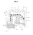
FIG. 4 shows a hydraulic clutch which employs a conventional piston-integrated seal, and FIG. 5 shows an outline structure of the conventional piston-integrated seal.
First of all, in the hydraulic clutch shown in FIG. 4, reference numeral 1 denotes an annular clutch cylinder which rotates together with a drive shaft (not shown), reference numeral 2 denotes a clutch piston which is arranged within the clutch cylinder 1 so as to be movable in an axial direction, and defines a hydraulic chamber S1 between the clutch piston and an end plate portion 11 of the clutch cylinder 1, reference numeral 3 denotes a spring holder which is arranged in a space S2 in an opposite side to the hydraulic chamber S1 as seen from the clutch piston 2 and is locked its inner diameter to an inner tube portion 13 of the clutch cylinder 1, reference numeral 4 denotes a return spring which is interposed between the clutch piston 2 and the spring holder 3 in an appropriately compressed state, and reference numeral 5 denotes a multiple disc clutch constructed by a plurality of drive plates 51 which are locked to the clutch cylinder 1 side in a circumferential direction under a movable state in an axial direction, and a plurality of driven plates 52 which are locked to a clutch hub 53 provided in a driven shaft side in a circumferential direction under a movable state in an axial direction.
This kind of hydraulic clutch is structured such that the piston 2 displaces in an axial direction within the clutch cylinder 1 by applying a hydraulic pressure to the hydraulic chamber S1 via a pressure guide port 14 which is provided in the inner tube portion 13 of the clutch cylinder 1 or releasing the hydraulic pressure, thereby friction fastening the drive plate 51 and the driven plate 52 of the multiple disc clutch 5 or canceling the friction fastening so as to carry out a clutch connection and disconnection motion.
A packing such as an O-ring has been conventionally used as a seal means for inner and outer peripheries of the clutch piston 2, however, the clutch piston 2 is desired to be lowered its friction in order to achieve an improvement of fuel consumption and a reduction of shift shock (a shock generated at the friction fastening time of the clutch). In recent years, a piston-integrated seal 100 having seal lips 101 and 101 has been a mainstream, the seal lips 101 and 101 being slidably brought into close contact with the outer tube portion 12 and the inner tube portion 13 of the clutch cylinder 1 while being directed to the hydraulic chamber S1 side. In other words, the piston-integrated seal 100 is integrally formed in the clutch piston 2 by a rubber-like elastic material (a rubber material or a synthetic resin material having a rubber-like elasticity) (refer, for example, to Japanese Unexamined Patent Publication No. 2001-241467).
As shown in FIG. 5, the seal lip 101 is generally structured such that an angle α of an inclined surface closer to the hydraulic chamber S1 side than the seal edge portion where a contact pressure P (an interference L) in relation to the other sliding surface shown by a two-dot chain line in the drawing is the greatest is larger than an angle β of an inclined surface in an opposite side, and a length Ha in an axial direction from the seal edge portion to the root portion in the opposite side to the hydraulic chamber S1 is comparatively long.
SUMMARY OF THE INVENTION Problem to be Solved by the Invention
However, according to the conventional piston-integrated seal 100, since the seal lip 101 has a directionality, a distribution of the contact pressure P is asymmetrical to each other in both sides of the maximum portion, and there is a tendency that the friction becomes greater at the stroking time of the clutch piston 2 to the clutch fastening canceling side (the hydraulic chamber S1 side) due to an energizing force of the return spring 4 when the hydraulic pressure of the hydraulic chamber S1 is released, in comparison with the stroking time of the clutch piston 2 to the clutch fastening side caused by applying the hydraulic pressure to the hydraulic chamber S1. As a result, it is hard to hydraulically control the hydraulic clutch, and there is a risk that a delay in shift change response is generated.
In order to improve the shift change response mentioned above, it is necessary to make a friction difference between the stroke to the clutch fastening canceling side (the hydraulic chamber S1 side) and the stroke to the clutch fastening side (the opposite side to the hydraulic chamber S1) small. Accordingly, reduction of the interference L and the rigidity of the seal lip 101 has been considered, however, there is a new problem that the pressure resistance and the durability of the seal lip 101 are lowered in this case.
Further, the friction can be reduced by forming a desired number of lubrication grooves in the sliding surface of the seal lip 101 (refer, for example, to Japanese Unexamined Patent Publication No. 9-210088). However, it has been insufficient to reduce the friction difference caused by the directionality of the seal lip 101.
The present invention is made by taking the above points into consideration, and a technical object of the present invention is to improve a shift change response of a hydraulic clutch by reducing a difference in friction due to a sliding direction caused by a directionality of a seal lip.
Means for Solving the Problem
As a means for effectively achieving the technical object mentioned above, a piston-integrated seal according to the invention of a first aspect has a seal lip which is integrally provided in a clutch piston of a hydraulic clutch and is directed to a hydraulic chamber side, the seal lip is structured such that a main seal edge portion in a hydraulic chamber side and a sub seal edge portion in an anti-hydraulic chamber side are formed in a sliding portion in relation to the other sliding surface, and the main seal edge portion and the sub seal edge portion are structured such that an angle of an inclined surface in the hydraulic chamber side is smaller than an angle of an inclined surface in the anti-hydraulic chamber side in a un-installed state, and the angle of the inclined surface in the hydraulic chamber side in relation to the other sliding surface is approximately equal to the angle of the inclined surface in the anti-hydraulic chamber side in an installed state.
A piston-integrated seal according to the invention of a second aspect is the structure described in the first aspect, wherein an interference of the sub seal edge portion is smaller than an interference of the main seal edge portion.
A piston-integrated seal according to the invention of a third aspect is the structure described in the first or second aspect, wherein the sub seal edge portion is positioned closer to the anti-hydraulic chamber side than a surface of a base portion in the hydraulic chamber side of the seal lip.
Effect of the Invention
On the basis of the piston-integrated seal according to the present invention, since the contact area with the other sliding surface is smaller by forming the main seal edge portion in the hydraulic chamber side and the sub seal edge portion in the anti-hydraulic chamber side, in the sliding portion of the seal lip, the friction can be reduced. Further, since the angle of the inclined surface in the hydraulic chamber side in relation to the other sliding surface is approximately equal to the angle of the inclined surface in the anti-hydraulic chamber side in the installed state (the contact state with the other sliding surface), it is possible to reduce the difference between the friction at the stroking time to the hydraulic chamber side and the friction at the stroking time to the anti-hydraulic chamber side. As a result, it is possible to improve the shift change response of the hydraulic clutch.
Further, according to the structure in which the interference of the sub seal edge portion is smaller than the interference of the main seal edge portion, since the deformation of the main seal edge portion can be absorbed by the sub seal edge portion, change in contact load of the main seal edge portion in relation to the other sliding surface can be suppressed regardless of change of the hydraulic pressure acting on the seal lip. As a result, it is possible to reduce the difference between the friction at the stroking time to the hydraulic chamber side and the friction at the stroking time to the anti-hydraulic chamber side.
Further, according to the structure in which the sub seal edge portion is positioned closer to the anti-hydraulic chamber side than the surface of the base portion in the hydraulic chamber side of the seal lip, since the deformation of the sub seal edge portion caused by applying the hydraulic pressure is suppressed, a seal lip deformation suppressing action by the sub seal edge portion is enhanced, and it is possible to improve the pressure resistance of the seal lip.
BRIEF EXPLANATION OF THE DRAWINGS
FIG. 1 is a one-side cross sectional view showing a preferable embodiment of a piston-integrated seal according to the present invention together with a part of a hydraulic clutch by cutting along a plane passing through an axis O;
FIG. 2 is an explanatory view showing a substantial part of the preferable embodiment of the piston-integrated seal according to the present invention;
FIG. 3 is an explanatory view showing angles of included surface in a un-installed state and an installed state in the substantial part of the preferable embodiment of the piston-integrated seal according to the present invention;
FIG. 4 is a one-side cross sectional view showing a conventional piston-integrated seal together with a part of a hydraulic clutch by cutting along a plane passing through an axis O; and
FIG. 5 is an explanatory view showing a part of the conventional piston-integrated seal.
DETAILED DESCRIPTION OF PREFERRED EMBODIMENT
A description will be given of a preferable embodiment of a piston-integrated seal according to the present invention with reference to the accompanying drawings. FIG. 1 is a one-side cross sectional view showing the piston-integrated seal according to the embodiment together with a part of a hydraulic clutch, reference numeral 1 denotes a clutch cylinder, reference numeral 2 denotes a clutch piston which is arranged within the clutch cylinder 1 so as to be movable in an axial direction and defines a hydraulic chamber S1 between the clutch piston and the clutch cylinder 1, reference numeral 1 denotes a spring holder which is arranged in a space (hereinafter, refer to as an anti-hydraulic chamber side space) S2 in an opposite side to the hydraulic chamber S1 as seen from the piston 2 and is locked to an inner tube portion 13 of the clutch cylinder 1 in its inner diameter portion, reference numeral 4 denotes a return spring which is interposed in an appropriately compressed state between the clutch piston 2 and the spring holder 3, and reference numeral 5 denotes a multiple disc clutch.
The clutch cylinder 1 has an end plate portion 11, and an outer tube portion 12 and an inner tube portion 13 which extend from an outer diameter and an inner diameter of the end plate portion, and is rotated around an axis O together with a drive shaft (not shown). Further, the inner tube portion 13 of the clutch cylinder 1 is provided with a pressure introduction port 14 for introducing a hydraulic pressure by an oil (ATF) to the hydraulic chamber S1.
The clutch piston 2 is a metal press molded product, and has a pressure receiving portion 21 which is faced to the end plate portion 11 of the clutch cylinder 1 in an axial direction, an outer tube portion 22 which extends from an outer diameter portion of the pressure receiving portion 21 to the anti-hydraulic chamber side space S2 side and faces to the outer tube portion 12 of the clutch cylinder 1 in a radial direction, and an inner tube portion 23 which extends from an inner diameter portion of the pressure receiving portion 21 to an opposite side to the hydraulic chamber S1 and faces to the inner tube portion 13 of the clutch cylinder 1 in a radial direction. A clutch pressing portion 24 is formed in a leading end portion of the outer tube portion 22 of the clutch piston 2, and an inward collar portion 25 is formed in a leading end portion of the inner tube portion 13 of the clutch piston 2.
The return spring 4 is structured such as to always energize the clutch piston 2 in a direction of reducing a cubic capacity of the hydraulic chamber S1 and is constructed by a coil spring. A plurality of return springs 4 are arranged at predetermined intervals in a circumferential direction.
The multiple disc clutch 5 is structured such that a plurality of drive plates 51 and a plurality of driven plates 52 are arranged alternately in an axial direction. The drive plates 51 are locked to the outer tube portion of the clutch cylinder 1 in a circumferential direction in a state in which the drive plates 51 can move in an axial direction, and the driven plates 52 are locked to a clutch hub 53 provided in a driven shaft side (not shown) in a circumferential direction in a state in which the driven shaft can move in an axial direction.
A piston-integrated seal 6 made of a rubber-like elastic material (a rubber material or a synthetic resin material having a rubber-like elasticity) is integrally provided in the clutch piston 2. The piston-integrated seal 6 has a base portion 61 which extends so as to cover an outer peripheral surface of the outer tube portion 22, a surface in the hydraulic chamber S1 side of the pressure receiving portion 21, an inner peripheral surface of the inner tube portion 23 and the inward collar portion 25 in the clutch piston 2, and seal lips 62 and 62 which are respectively positioned in the vicinity of an outer diameter portion of the pressure receiving portion 21 and an inner diameter of the inward collar portion 25 and are formed so as to extend from the base portion 61 to the hydraulic chamber S1 side. The seal 62 lip in the outer peripheral side is slidably brought into close contact with the inner peripheral surface of the outer tube portion 12 in the clutch cylinder 1, and the seal lip 62 in the inner peripheral side is slidably brought into close contact with the outer peripheral surface of the inner tube portion 13 in the clutch cylinder 1.
Further, a plurality of projections 63 are formed at uniform intervals in a circumferential direction in a portion which is bonded to the pressure receiving portion 21 of the clutch piston 2, in the base portion 61 of the piston-integrated seal 6. The projections 63 prevent occlusion of the hydraulic chamber S1 by the close contact of the base portion 61 with the end plate portion 11 of the clutch cylinder 1 when the clutch piston 2 moves to its top dead center position.
The seal lip 62 is structured, as shown in FIG. 2 in an enlarged manner, such that a main seal edge portion 62 a in the hydraulic chamber S1 side and a sub seal edge portion 62 b in the anti-hydraulic chamber side space S2 side are formed in a sliding portion with an inner peripheral surface of the outer tube portion 12 of the clutch cylinder 1 or an outer peripheral surface of the inner tube portion 13.
Describing in detail, a protruding height of the sub seal edge portion 62 b is lower than a protruding height of the main seal edge portion 62 a. As a result, an interference L2 of the sub seal edge portion 62 b is set smaller than an interference L1 of the main seal edge portion 62 a in relation to the inner peripheral surface of the outer tube portion 12 or the outer peripheral surface of the inner tube portion 13 of the clutch cylinder shown by a two-dot chain line in FIG. 2. Further, the protruding height of the sub seal edge portion 62 b is formed to be lower than the inner peripheral surface of the conventionally shaped seal lip shown by a broken line in FIG. 2.
As shown in FIG. 2, a length Ha0 from the main seal edge portion 62 a to the root portion in the anti-hydraulic chamber side space S2 side is shorter than a length Ha in an axial direction from the seal edge portion of the seal lip 101 according to the prior art shown in FIG. 5 which is previously described to the root portion in the anti-hydraulic chamber side space S2 side. Further, a length Hal in an axial direction between the main seal edge portion 62 a and the sub seal edge portion 62 b is shorter than a length Ha2 in an axial direction from the sub seal edge portion 62 b to the root portion.
The main seal edge portion 62 a exists only a distance Hb1 in an axial direction closer to the hydraulic chamber S1 side than a base portion surface 61 a in the hydraulic chamber S1 side of the seal lip 62 in the base portion 61, however, the sub seal edge portion 62 b exists only a distance Hb2 in an axial direction closer to an opposite side (the space S2 side) to the hydraulic chamber S1 than the base portion surface 61 a. An expression Hb1+Hb2=Ha1 is established.
Further, as shown in FIG. 3, the main seal edge portion 62 a is formed so that an angle α1 of an inclined surface corresponding to the hydraulic chamber S1 side is smaller than an angle β1 of an inclined surface corresponding to the opposite side (the space S2 side) to the hydraulic chamber S111) under a un-installed state, and the sub seal edge portion 62 b is formed so that an angle α2 of an inclined surface corresponding to the hydraulic chamber S1 side is smaller than an angle β2 of an inclined surface corresponding to the opposite side (the space S2 side) to the hydraulic chamber S122) under a un-installed state. Further, an expression α12 and an expression β12 are established.
As a result, since the seal lip 62 is exposed to a bending deformation around its root under the installed state, an angle α1′ which the inclined surface in the hydraulic chamber S1 side of the main seal edge portion 62 a forms in relation to the inner peripheral surface of the outer tube portion 12 or the outer peripheral surface of the inner tube portion 13 in the clutch cylinder is increased somewhat in relation to α1, and an angle β1′ which the inclined surface in the anti-hydraulic chamber side space S2 side forms is inversely reduced somewhat in relation to β1. As a result, an expression α1′≅β1′ is established. Same applies to the sub seal edge portion 62 b, an angle α2′ which the inclined surface in the hydraulic chamber S1 side forms is increased somewhat in relation to α2 under the installed state, and an angle β2′ which the inclined surface in the anti-hydraulic chamber side space S2 side forms is inversely reduced somewhat in relation to β2. As a result, an expression α2′≅β2′ is established.
Since the hydraulic clutch having the structure mentioned above applies the hydraulic pressure to the hydraulic chamber S1 via the pressure introduction port 14 or releases the hydraulic pressure, the clutch piston 2 displaces in the axial direction within the clutch cylinder 1, and the hydraulic clutch makes the multiple disc clutch 5 carry out a connecting action or a disconnecting action.
More specifically, in the case that the hydraulic chamber S1 is pressurized by feeding the oil (ATF), the clutch piston 2 displaces to a downward side in FIG. 1 (the anti-hydraulic chamber side space S2 side) while compressing the return spring 4, and the clutch pressing portion 24 of the clutch piston 2 presses the multiple disc clutch 5 so as to engage frictionally the drive plate 51 and the driven plate 52. As a result, the multiple disc clutch 5 comes to a connected state, and a driving torque from the drive shaft (not shown) side is transmitted to the driven shaft (not shown) via the clutch cylinder 1, and the drive plate 51, the driven plate 52 and the clutch hub 53 of the multiple disc clutch 5.
Further, in the case that the hydraulic pressure of the hydraulic chamber S1 is released from the connected state, the clutch piston 2 displaces upward in FIG. 1 on the basis of the elongation of the compressed return spring 4 so as to reduce the cubic capacity of the hydraulic chamber S1, and cancels the pressure application to the multiple disc clutch 5. As a result, the friction engagement between the drive plate 51 and the driven plate 52 of the multiple disc clutch 5 is canceled, and the transmission of the driving torque from the drive shaft to the driven shaft is disconnected.
In the displacement of the clutch piston 2 mentioned above, in the piston-integrated seal 6 integrally provided in the clutch piston 2, the seal lips 62 in its inner and outer peripheries come into close contact with and slides along the inner peripheral surface of the outer tube portion 12 and the outer peripheral surface of the inner tube portion 13 of the clutch cylinder 1. Further, since the main seal edge portion 62 a in the hydraulic chamber S1 side and the sub seal edge portion 62 b in the anti-hydraulic chamber side space S2 side are formed in the sliding portion, the contact area with the outer tube portion 12 and the inner tube portion 13 of the clutch cylinder 1 becomes smaller. In addition, since the thickness of the seal lip 62 is reduced as a whole in comparison with the conventional shape shown by a broken line in FIG. 2, the rigidity is lowered. As a result, the contact pressures P1 and P2 by the main seal edge portion 62 a and the sub seal edge portion 62 b shown in FIG. 3 become smaller as a whole in comparison with the conventional contact pressure shown by the broken line. Further, since the portion between both the seal edge portions 62 a and 62 b serves as the lubrication groove, the friction can be effectively reduced.
Further, in a state in which the seal lip 62 comes into contact with the inner peripheral surface of the outer tube portion 12 or the outer peripheral surface of the inner tube portion 13 in the clutch cylinder as shown by [installed state] in FIG. 3, the angle α1′ of the inclined surface in the hydraulic chamber S1 side of the main seal edge portion 62 a is approximately equal to the angle β1′ of the inclined surface in the anti-hydraulic chamber side space S2 side, and the angle α2′ of the inclined surface in the hydraulic chamber S1 side of the sub seal edge portion 62 b is approximately equal to the angle β2′ of the inclined surface in the anti-hydraulic chamber side space S2 side. As a result, the contact pressures P1 and P2 of the main seal edge portion 62 a and the sub seal edge portion 62 b in relation to the inner peripheral surface of the outer tube portion 12 or the outer peripheral surface of the inner tube portion 13 in the clutch cylinder distribute respectively approximately and symmetrically with each other in the hydraulic chamber S1 side and the anti-hydraulic chamber side space S2 side. Therefore, it is possible to effectively reduce the difference between the friction at the stroking time of the clutch piston 2 to the anti-hydraulic chamber side space S2 side (the direction of pressing the multiple disc clutch 5), and the friction at the stroking time of the clutch piston 2 to the hydraulic chamber S1 side (the direction of canceling the pressure application to the multiple disc clutch 5). As a result, it is possible to improve the shift change response of the hydraulic clutch.
Further, since the interference L2 of the sub seal edge portion 62 b is set to be smaller than the interference L1 of the main seal edge portion 62 a in relation to the inner peripheral surface of the outer tube portion 12 or the outer peripheral surface of the inner tube portion 13 in the clutch cylinder, as shown in FIG. 2, the deformation of the main seal edge portion 62 a can be absorbed by the sub seal edge portion 62 b. As a result, the change of the contact load of the main seal edge portion 62 a can be suppressed regardless of the change of the hydraulic pressure of the hydraulic chamber S1 applied to the seal lip 62, and the difference in friction mentioned above can be reduced thereby.
Further, since the sub seal edge portion 62 b is positioned only the distance Hb2 in the axial direction closer to the anti-hydraulic chamber side space S2 side than the base portion surface 61 a in the hydraulic chamber S1 side of the seal lip 62 in the base portion 61, the deformation of the sub seal edge portion 62 b caused by applying the hydraulic pressure to the hydraulic chamber S1 is suppressed. As a result, a deformation suppressing action of the seal lip 62 by the sub seal edge portion 62 b is enhanced. Further, since the length Ha0 itself from the main seal edge portion 62 a to the root portion in the anti-hydraulic chamber side space S2 side is made shorter than the conventional one shown in FIG. 5, it is possible to improve the pressure resistance in spite of the matter that the thickness of the seal lip 62 is smaller than the conventional one.

Claims (4)

What is claimed is:
1. A piston-integrated seal comprising:
a seal lip which is integrally provided in a clutch piston of a hydraulic clutch and is directed to a hydraulic chamber side,
wherein the seal lip is structured such that a main seal edge portion on a hydraulic chamber side of the seal lip and a sub seal edge portion on an anti-hydraulic chamber side of the seal lip are formed in a sliding portion in relation to another sliding surface,
wherein the main seal edge portion has a first inclined surface on the hydraulic chamber side and a second inclined surface on the anti-hydraulic chamber side and is structured such that;
in an un-installed state, an angle α1 of the first inclined surface is smaller than an angle β1 of the second inclined surface, and
in an installed state, an angle α1′ of the first inclined surface in relation to the other sliding surface is approximately equal to an angle β1′ of the second inclined surface in relation to the other sliding surface , and
wherein the sub seal edge portion has a third inclined surface on the hydraulic chamber side and a fourth inclined surface on the anti-hydraulic chamber side and is structured such that:
in an un-installed state, an angle α2 of the third inclined surface is smaller than an angle β2 of the fourth inclined surface, and
in an installed state, an anole α2′ of the third inclined surface in relation to the other sliding surface is approximately equal to an angle β2′ of the fourth inclined surface in relation to the other sliding surface.
2. The piston-integrated seal according to claim 1, wherein an interference of the sub seal edge portion is smaller than an interference of the main seal edge portion.
3. The piston-integrated seal according to claim 1, wherein the sub seal edge portion is positioned closer to the anti-hydraulic chamber side than a surface of a base portion in the hydraulic chamber side of the seal lip.
4. The piston-integrated seal according to claim 2, wherein the sub seal edge portion is positioned closer to the anti-hydraulic chamber side than a surface of a base portion in the hydraulic chamber side of the seal lip.
US14/892,305 2013-05-24 2013-10-29 Piston-integrated seal Active US9482292B2 (en)

Applications Claiming Priority (3)

Application Number Priority Date Filing Date Title
JP2013-109509 2013-05-24
JP2013109509A JP6117000B2 (en) 2013-05-24 2013-05-24 Piston integrated seal
PCT/JP2013/079187 WO2014188616A1 (en) 2013-05-24 2013-10-29 Piston-integrated seal

Publications (2)

Publication Number Publication Date
US20160091033A1 US20160091033A1 (en) 2016-03-31
US9482292B2 true US9482292B2 (en) 2016-11-01

Family

ID=51933195

Family Applications (1)

Application Number Title Priority Date Filing Date
US14/892,305 Active US9482292B2 (en) 2013-05-24 2013-10-29 Piston-integrated seal

Country Status (6)

Country Link
US (1) US9482292B2 (en)
EP (1) EP3006762B1 (en)
JP (1) JP6117000B2 (en)
KR (1) KR102080668B1 (en)
CN (1) CN105247234B (en)
WO (1) WO2014188616A1 (en)

Cited By (2)

* Cited by examiner, † Cited by third party
Publication number Priority date Publication date Assignee Title
US11592108B2 (en) * 2019-09-19 2023-02-28 Aktiebolaget Skf Seal having a lip optimized for low temperature applications
FR3129998A1 (en) * 2021-12-03 2023-06-09 Valeo Embrayages Wet clutch

Families Citing this family (3)

* Cited by examiner, † Cited by third party
Publication number Priority date Publication date Assignee Title
JP2019203524A (en) * 2018-05-21 2019-11-28 Nok株式会社 Clutch piston
JP2020076478A (en) * 2018-11-09 2020-05-21 Nok株式会社 Piston seal for automatic transmission
IT201900016034A1 (en) 2019-09-11 2021-03-11 Skf Ab SEALING DEVICE IN PARTICULAR FOR SHOCK ABSORBER STEMS

Citations (20)

* Cited by examiner, † Cited by third party
Publication number Priority date Publication date Assignee Title
GB2156481A (en) 1984-03-30 1985-10-09 Kugelfischer G Schaefer & Co Rocking piston structure for hydraulic system
US5172793A (en) * 1990-06-21 1992-12-22 Allied-Signal Inc. Vehicle brake with brake cylinder bore insert
JPH08184377A (en) 1994-11-04 1996-07-16 Nok Corp Sealing device for reciprocation
JPH09210088A (en) 1996-01-29 1997-08-12 Nok Corp Sealing device
JPH09292031A (en) 1996-04-24 1997-11-11 Nok Corp Sealing device for reciprocating motion
US5865442A (en) * 1996-06-12 1999-02-02 Kurashiki Kako Co., Ltd. Lip-like seal
DE19839502A1 (en) 1998-08-29 2000-03-09 Freudenberg Carl Fa Sealing ring for rotating shafts and reciprocating bars comprises at least two sealing lips of which only the one next to the medium to be sealed off is made of polytetrafluoroethylene
US6039160A (en) * 1998-08-31 2000-03-21 General Motors Corporation Friction torque transmitter with a one-way actuator
JP2001241467A (en) 2000-02-29 2001-09-07 Mitsubishi Cable Ind Ltd Cancel plate
US6543783B1 (en) 1997-02-26 2003-04-08 Firma Carl Freudenberg Sealing ring with sloping support body
DE10222933A1 (en) 2002-05-24 2003-12-04 Zf Sachs Ag Hydraulically actuated clutch device with at least one bleedable or flushable hydraulic slave cylinder and corresponding hydraulic slave cylinder arrangement
WO2004023007A1 (en) 2002-09-09 2004-03-18 Nok Corporation Sealing device
US20040251107A1 (en) 2003-03-25 2004-12-16 Sefcik Michael C. Clutch housing with multi-function hydraulic sleeve
US7156399B2 (en) * 2002-07-02 2007-01-02 Koyo Seiko Co., Ltd. Sealing device and sliding member
WO2007102411A1 (en) 2006-03-07 2007-09-13 Dynax Corporation Seal structure of canceller in wet clutch
US20070251380A1 (en) * 2004-03-19 2007-11-01 Nok Corporation Piston
US20100025937A1 (en) * 2008-07-31 2010-02-04 Toyota Jidosha Kabushiki Kaisha Sealing device
JP2011149512A (en) 2010-01-22 2011-08-04 Koyo Sealing Techno Co Ltd Clutch piston for torque converter
WO2012024470A1 (en) 2010-08-18 2012-02-23 Skf Usa Inc. Seal with pressure-actuatable sealing bead
JP2013096503A (en) 2011-11-01 2013-05-20 Kyb Co Ltd Sealing device, and damper with sealing device

Family Cites Families (1)

* Cited by examiner, † Cited by third party
Publication number Priority date Publication date Assignee Title
JPH1151197A (en) * 1997-07-31 1999-02-23 Koyo Seiko Co Ltd Clutch piston of fluid type transmission

Patent Citations (23)

* Cited by examiner, † Cited by third party
Publication number Priority date Publication date Assignee Title
GB2156481A (en) 1984-03-30 1985-10-09 Kugelfischer G Schaefer & Co Rocking piston structure for hydraulic system
US5172793A (en) * 1990-06-21 1992-12-22 Allied-Signal Inc. Vehicle brake with brake cylinder bore insert
JPH08184377A (en) 1994-11-04 1996-07-16 Nok Corp Sealing device for reciprocation
JPH09210088A (en) 1996-01-29 1997-08-12 Nok Corp Sealing device
US5899461A (en) 1996-01-29 1999-05-04 Nok Corporation Sealing apparatus
JPH09292031A (en) 1996-04-24 1997-11-11 Nok Corp Sealing device for reciprocating motion
US5865442A (en) * 1996-06-12 1999-02-02 Kurashiki Kako Co., Ltd. Lip-like seal
US6543783B1 (en) 1997-02-26 2003-04-08 Firma Carl Freudenberg Sealing ring with sloping support body
DE19839502A1 (en) 1998-08-29 2000-03-09 Freudenberg Carl Fa Sealing ring for rotating shafts and reciprocating bars comprises at least two sealing lips of which only the one next to the medium to be sealed off is made of polytetrafluoroethylene
US6039160A (en) * 1998-08-31 2000-03-21 General Motors Corporation Friction torque transmitter with a one-way actuator
JP2001241467A (en) 2000-02-29 2001-09-07 Mitsubishi Cable Ind Ltd Cancel plate
DE10222933A1 (en) 2002-05-24 2003-12-04 Zf Sachs Ag Hydraulically actuated clutch device with at least one bleedable or flushable hydraulic slave cylinder and corresponding hydraulic slave cylinder arrangement
US7156399B2 (en) * 2002-07-02 2007-01-02 Koyo Seiko Co., Ltd. Sealing device and sliding member
US20050272508A1 (en) 2002-09-09 2005-12-08 Hiroki Matsui Sealing device
WO2004023007A1 (en) 2002-09-09 2004-03-18 Nok Corporation Sealing device
US20040251107A1 (en) 2003-03-25 2004-12-16 Sefcik Michael C. Clutch housing with multi-function hydraulic sleeve
US20070251380A1 (en) * 2004-03-19 2007-11-01 Nok Corporation Piston
WO2007102411A1 (en) 2006-03-07 2007-09-13 Dynax Corporation Seal structure of canceller in wet clutch
US20100025937A1 (en) * 2008-07-31 2010-02-04 Toyota Jidosha Kabushiki Kaisha Sealing device
JP2011149512A (en) 2010-01-22 2011-08-04 Koyo Sealing Techno Co Ltd Clutch piston for torque converter
WO2012024470A1 (en) 2010-08-18 2012-02-23 Skf Usa Inc. Seal with pressure-actuatable sealing bead
US9194496B2 (en) * 2010-08-18 2015-11-24 Aktiebolaget Skf Seal with pressure-actuatable sealing bead
JP2013096503A (en) 2011-11-01 2013-05-20 Kyb Co Ltd Sealing device, and damper with sealing device

Non-Patent Citations (1)

* Cited by examiner, † Cited by third party
Title
Extended European Search Report for EP Application No. 13885064.9 dated Mar. 21, 2016 (8 pages).

Cited By (2)

* Cited by examiner, † Cited by third party
Publication number Priority date Publication date Assignee Title
US11592108B2 (en) * 2019-09-19 2023-02-28 Aktiebolaget Skf Seal having a lip optimized for low temperature applications
FR3129998A1 (en) * 2021-12-03 2023-06-09 Valeo Embrayages Wet clutch

Also Published As

Publication number Publication date
EP3006762A4 (en) 2016-04-20
KR102080668B1 (en) 2020-02-24
KR20160011646A (en) 2016-02-01
WO2014188616A1 (en) 2014-11-27
CN105247234B (en) 2018-08-31
CN105247234A (en) 2016-01-13
US20160091033A1 (en) 2016-03-31
JP2014228089A (en) 2014-12-08
JP6117000B2 (en) 2017-04-19
EP3006762B1 (en) 2018-07-04
EP3006762A1 (en) 2016-04-13

Similar Documents

Publication Publication Date Title
US9482292B2 (en) Piston-integrated seal
US20100295253A1 (en) Packing and sealing system
WO2015151643A1 (en) Transmission brake device
CN101523072A (en) Piston with built-in seal
JP2015222100A (en) Transmission brake system
US20070251380A1 (en) Piston
US8607689B2 (en) Seal member for a hydraulic braking system
JP2004084676A (en) Sliding member and sealing device
JP2013194884A (en) Sealing device
JP5574090B2 (en) Reciprocating seal ring
JP2010133511A (en) Sealing device
US9447878B2 (en) Piston seal assembly
US9677625B2 (en) Concentric slave cylinder including one-way clutch
KR20160128300A (en) Center bearing of adapter plate comprising rubber and rigid plastic members developed for spring brake actuators
US10100881B2 (en) Clutch seal
US20090038906A1 (en) Seal integral type piston
US9068604B2 (en) Friction clutch and plate with partially raised segment joints
KR101208885B1 (en) Rubber Ring for Clutch Piston of Multi-plate Clutch System of Auto Transmission
JP4507116B2 (en) Sliding member and sealing device
CN217355024U (en) Heavy-duty hydraulic oil cylinder piston sealing structure
CN210344268U (en) Heavy-load coaxial piston sealing ring
CN201982550U (en) Dual-sealing hydraulic rear wheel cylinder
WO2020230466A1 (en) Hydraulic actuator sealing device
JP2006144901A (en) Reciprocation seal
JP2006177501A (en) Sealing device

Legal Events

Date Code Title Description
AS Assignment

Owner name: NOK CORPORATION, JAPAN

Free format text: ASSIGNMENT OF ASSIGNORS INTEREST;ASSIGNORS:OZAWA, KENTARO;GOTO, KIICHIRO;REEL/FRAME:037087/0222

Effective date: 20151008

STCF Information on status: patent grant

Free format text: PATENTED CASE

MAFP Maintenance fee payment

Free format text: PAYMENT OF MAINTENANCE FEE, 4TH YEAR, LARGE ENTITY (ORIGINAL EVENT CODE: M1551); ENTITY STATUS OF PATENT OWNER: LARGE ENTITY

Year of fee payment: 4

MAFP Maintenance fee payment

Free format text: PAYMENT OF MAINTENANCE FEE, 8TH YEAR, LARGE ENTITY (ORIGINAL EVENT CODE: M1552); ENTITY STATUS OF PATENT OWNER: LARGE ENTITY

Year of fee payment: 8