US9446907B2 - Zone controller and conveyor device - Google Patents
Zone controller and conveyor device Download PDFInfo
- Publication number
- US9446907B2 US9446907B2 US14/386,180 US201314386180A US9446907B2 US 9446907 B2 US9446907 B2 US 9446907B2 US 201314386180 A US201314386180 A US 201314386180A US 9446907 B2 US9446907 B2 US 9446907B2
- Authority
- US
- United States
- Prior art keywords
- signal
- zone
- zone controller
- node number
- abnormality alarm
- Prior art date
- Legal status (The legal status is an assumption and is not a legal conclusion. Google has not performed a legal analysis and makes no representation as to the accuracy of the status listed.)
- Active
Links
- 230000005856 abnormality Effects 0.000 claims abstract description 193
- 238000012545 processing Methods 0.000 claims abstract description 79
- 230000008054 signal transmission Effects 0.000 claims abstract description 33
- 238000000034 method Methods 0.000 claims description 8
- 230000008569 process Effects 0.000 claims description 8
- 230000008859 change Effects 0.000 claims description 4
- 230000002950 deficient Effects 0.000 abstract description 6
- 230000007547 defect Effects 0.000 abstract description 3
- 230000006870 function Effects 0.000 description 65
- 238000001514 detection method Methods 0.000 description 10
- 230000007274 generation of a signal involved in cell-cell signaling Effects 0.000 description 6
- 238000012360 testing method Methods 0.000 description 6
- 238000011144 upstream manufacturing Methods 0.000 description 4
- 230000002159 abnormal effect Effects 0.000 description 3
- 230000005540 biological transmission Effects 0.000 description 3
- 238000004891 communication Methods 0.000 description 2
- 238000009825 accumulation Methods 0.000 description 1
- 230000008901 benefit Effects 0.000 description 1
- 229910002056 binary alloy Inorganic materials 0.000 description 1
- 230000000694 effects Effects 0.000 description 1
- 238000009434 installation Methods 0.000 description 1
- 238000012423 maintenance Methods 0.000 description 1
- 230000008439 repair process Effects 0.000 description 1
Images


Classifications
-
- B—PERFORMING OPERATIONS; TRANSPORTING
- B65—CONVEYING; PACKING; STORING; HANDLING THIN OR FILAMENTARY MATERIAL
- B65G—TRANSPORT OR STORAGE DEVICES, e.g. CONVEYORS FOR LOADING OR TIPPING, SHOP CONVEYOR SYSTEMS OR PNEUMATIC TUBE CONVEYORS
- B65G43/00—Control devices, e.g. for safety, warning or fault-correcting
- B65G43/10—Sequence control of conveyors operating in combination
-
- G—PHYSICS
- G05—CONTROLLING; REGULATING
- G05B—CONTROL OR REGULATING SYSTEMS IN GENERAL; FUNCTIONAL ELEMENTS OF SUCH SYSTEMS; MONITORING OR TESTING ARRANGEMENTS FOR SUCH SYSTEMS OR ELEMENTS
- G05B19/00—Programme-control systems
- G05B19/02—Programme-control systems electric
- G05B19/04—Programme control other than numerical control, i.e. in sequence controllers or logic controllers
- G05B19/042—Programme control other than numerical control, i.e. in sequence controllers or logic controllers using digital processors
-
- G—PHYSICS
- G05—CONTROLLING; REGULATING
- G05B—CONTROL OR REGULATING SYSTEMS IN GENERAL; FUNCTIONAL ELEMENTS OF SUCH SYSTEMS; MONITORING OR TESTING ARRANGEMENTS FOR SUCH SYSTEMS OR ELEMENTS
- G05B19/00—Programme-control systems
- G05B19/02—Programme-control systems electric
- G05B19/418—Total factory control, i.e. centrally controlling a plurality of machines, e.g. direct or distributed numerical control [DNC], flexible manufacturing systems [FMS], integrated manufacturing systems [IMS], computer integrated manufacturing [CIM]
- G05B19/4185—Total factory control, i.e. centrally controlling a plurality of machines, e.g. direct or distributed numerical control [DNC], flexible manufacturing systems [FMS], integrated manufacturing systems [IMS], computer integrated manufacturing [CIM] characterised by the network communication
-
- G—PHYSICS
- G05—CONTROLLING; REGULATING
- G05B—CONTROL OR REGULATING SYSTEMS IN GENERAL; FUNCTIONAL ELEMENTS OF SUCH SYSTEMS; MONITORING OR TESTING ARRANGEMENTS FOR SUCH SYSTEMS OR ELEMENTS
- G05B2219/00—Program-control systems
- G05B2219/20—Pc systems
- G05B2219/24—Pc safety
- G05B2219/24033—Failure, fault detection and isolation
-
- G—PHYSICS
- G05—CONTROLLING; REGULATING
- G05B—CONTROL OR REGULATING SYSTEMS IN GENERAL; FUNCTIONAL ELEMENTS OF SUCH SYSTEMS; MONITORING OR TESTING ARRANGEMENTS FOR SUCH SYSTEMS OR ELEMENTS
- G05B2219/00—Program-control systems
- G05B2219/30—Nc systems
- G05B2219/33—Director till display
- G05B2219/33145—Count clock pulses to determine address of node, module
-
- G—PHYSICS
- G05—CONTROLLING; REGULATING
- G05B—CONTROL OR REGULATING SYSTEMS IN GENERAL; FUNCTIONAL ELEMENTS OF SUCH SYSTEMS; MONITORING OR TESTING ARRANGEMENTS FOR SUCH SYSTEMS OR ELEMENTS
- G05B2219/00—Program-control systems
- G05B2219/30—Nc systems
- G05B2219/33—Director till display
- G05B2219/33226—Daisy chain
-
- G—PHYSICS
- G05—CONTROLLING; REGULATING
- G05B—CONTROL OR REGULATING SYSTEMS IN GENERAL; FUNCTIONAL ELEMENTS OF SUCH SYSTEMS; MONITORING OR TESTING ARRANGEMENTS FOR SUCH SYSTEMS OR ELEMENTS
- G05B2219/00—Program-control systems
- G05B2219/30—Nc systems
- G05B2219/45—Nc applications
- G05B2219/45054—Handling, conveyor
-
- Y—GENERAL TAGGING OF NEW TECHNOLOGICAL DEVELOPMENTS; GENERAL TAGGING OF CROSS-SECTIONAL TECHNOLOGIES SPANNING OVER SEVERAL SECTIONS OF THE IPC; TECHNICAL SUBJECTS COVERED BY FORMER USPC CROSS-REFERENCE ART COLLECTIONS [XRACs] AND DIGESTS
- Y02—TECHNOLOGIES OR APPLICATIONS FOR MITIGATION OR ADAPTATION AGAINST CLIMATE CHANGE
- Y02P—CLIMATE CHANGE MITIGATION TECHNOLOGIES IN THE PRODUCTION OR PROCESSING OF GOODS
- Y02P90/00—Enabling technologies with a potential contribution to greenhouse gas [GHG] emissions mitigation
- Y02P90/02—Total factory control, e.g. smart factories, flexible manufacturing systems [FMS] or integrated manufacturing systems [IMS]
-
- Y02P90/10—
-
- Y02P90/18—
-
- Y02P90/28—
Definitions
- the present invention relates to a conveyor device of a distributed control type and, more particularly, to a conveyor device which is capable of easily identifying an abnormal part when an abnormality such as a failure occurs, and easily performing communication with a host controller.
- the present invention also relates to a zone controller used for the distributed control type conveyor device.
- a conveyor device is used in a delivery center of a home delivery company or a post office.
- the conveyor device there are known a roller conveyor device in which cylindrical conveying rollers are arranged along a conveyance line, a belt conveyor device in which a conveying belt is mounted in a stretched state, and the like.
- a distributed control system (Patent Document 1).
- a plurality of zone conveyors are arranged in series to form a continuous conveying path.
- Each zone conveyor is provided with an independent motor.
- each zone conveyor is provided with a zone controller, and the zone controller manages/controls the corresponding zone conveyor.
- the zone controller outputs a motor drive signal and receives a signal from a load presence sensor provided in each zone.
- the zone controller is provided with a communication function and exchanges a signal with the adjacent zone controllers.
- information indicating an ON/OFF state of the load presence sensor or information indicating whether or not the motor is activated is exchanged between adjacent zone controllers.
- the zone controller activates the motor of the corresponding zone to convey the conveying object to the downstream side zone.
- the distributed control type conveyor device has an advantage that a layout can easily be changed. For example, when an overall length of the conveyor device is to be extended, a new zone conveyor is mounted to an end or middle portion of the existing conveyor device. On the other hand, when the overall length of the conveyor device is to be reduced, any of the zone conveyors may be removed, and a generated space may be eliminated.
- Patent Document 1 JP 2005-231745 A
- the distributed control type conveyor device has drawback in that, when a failure or the like occurs, a failure part cannot be easily identified. Further, it is difficult to identify a defective part in a test run.
- the conveyor device is provided with a large number of motors and sensors, which increases a failure occurrence frequency. Further, while the motors or sensors need to be subjected to wiring one by one at installation of the conveyor device, erroneous wiring may occur.
- the defective part needs to be identified so as to repair or correct the failure.
- the distributed control type conveyor device does not originally have a central controller or, even if it has the central controller, the function thereof is restrictive. That is, even if there is the central controller, individual motors or sensors are not directly connected to the central controller, and thus the central controller cannot grasp which component in which zone has the defect.
- the distributed control type conveyor device power supply to the motor in each zone or input/output of a signal of the sensor in each zone is performed through the zone controller that manages/controls the corresponding zone conveyor.
- the zone controller that manages/controls the corresponding zone conveyor.
- the present invention has been made in view of the above conventional problems, and an object thereof is to provide a zone controller and a conveyor device capable of easily identifying a defective part such as a failure part.
- a zone controller which is used for a conveyor device in which a plurality of zone conveyors are arranged in series, which manages one or a plurality of the zone conveyors to control an operation thereof, and which is configured to receive a signal from a different zone controller and transmit a signal to an outside
- the zone controller including: a signal creation function that creates a predetermined abnormality alarm signal and transmits the created abnormality alarm signal to the outside when an abnormality occurs in a zone managed by the zone controller itself; a signal reception function that receives the abnormality alai in signal from the different zone controller; a signal processing function that applies certain processing to the received abnormality alarm signal; and a processed signal transmission function that transmits the signal processed by the signal processing function to the outside as the abnormality alarm signal.
- the zone controller according to the present aspect is used for a conveyor device in which a plurality of zone conveyors are arranged in series, and controls the conveyor device in a distributed manner.
- the zone controller can receive a signal from another zone controller and can transmit a signal to the outside, thereby allowing signal exchange with adjacent zone controllers. For example, information indicating an ON/OFF state of the load presence sensor in the adjacent zones or information indicating whether or not the motor in the adjacent zones is activated is exchanged between adjacent zone controllers, thereby allowing a conveying object to be conveyed to the adjacent zone.
- the zone controller includes the signal creation function, and creates a predetermined abnormality alarm signal and transmits the created abnormality alarm signal to the outside when an abnormality occurs in a zone managed by the zone controller itself.
- the abnormality alarm signal is received by an adjacent zone controller.
- certain processing is applied to the received abnormality alarm signal.
- the adjacent zone controller transmits the signal processed using the signal processing function to the outside as the abnormality alarm signal.
- a zone controller adjacently disposed to the adjacent zone controller receives the abnormality alarm signal after processing, and again applies processing to the processed abnormality alarm signal.
- the abnormality alarm signal transmitted from such a zone controller is a signal that has been processed twice. In this manner, the abnormality alarm signal sequentially passes through the adjacent zone controllers while being subjected to processing. That is, reception, processing, and transmission of the abnormality alarm signal are performed in the zone controllers in a successive manner.
- the abnormality alarm signal reaches a specific (e.g., endmost) zone controller. Then, the abnormality alarm signal transmitted from this specific (e.g., endmost) zone controller is analyzed to examine a processed state, whereby a zone controller that has first created the abnormality alarm signal can be identified.
- a specific zone controller e.g., endmost
- the abnormality alarm signal transmitted from a zone controller of a zone in which an abnormality has actually occurred is a signal that has not been subjected to processing at all.
- the abnormality alarm signal transmitted from the adjacent zone controller is a signal that has been subjected to processing once.
- the abnormality alarm signal transmitted from the next adjacent zone controller is a signal that has been subjected to processing twice
- the abnormality alarm signal transmitted from the further adjacent zone controller is a signal that has been subjected to processing three times. That is, by going back along a signal transmission path by the number of times of processing, a zone controller of a zone in which an abnormality has actually occurred can be identified.
- the abnormality alarm signal created by the signal creation function is a pulse signal having a fixed time length, and the signal processing function increases or reduces a pulse width of the pulse signal.
- the present aspect there is a correlation between the number of the zone controllers through which the abnormality alarm signal passes along a signal transmission path and a pulse width (time length of the abnormality alarm signal).
- a zone controller of a zone in which an abnormality has actually occurred can be retrieved.
- the predetermined signal created by the signal creation function is a pulse signal having a fixed time length
- the signal processing function adds or subtracts a new pulse to or from the pulse signal to increase or reduce the number of pulses.
- the present aspect there is a correlation between the number of the zone controllers through which the abnormality alarm signal passes along a signal transmission path and the number of pulses of the abnormality alarm signal.
- a zone controller of a zone in which an abnormality has actually occurred can be retrieved.
- a zone controller which is used for a conveyor device in which a plurality of zone conveyors are arranged in series, which manages one or a plurality of the zone conveyors to control an operation thereof, and which is configured to receive a signal from a different zone controller and transmit a signal to an outside
- the zone controller including: a signal reception function that receives a pulse signal from the different zone controller; a signal processing function that applies certain processing to the received pulse signal based on a certain function; and a processed signal transmission function that transmits the signal processed by the signal processing function to the outside.
- the zone controller transmits to the outside a signal added with information for identifying the zone controller itself.
- This facilitates exchange of a control signal between a device such as a central controller configured to transmit a control signal to each of the zone controllers constituting the conveyor device and a specific controller of the plurality of zone controllers. This facilitates control with respect to only the specific controller out of the plurality of zone controllers.
- the zone controller further includes a storage unit that stores the signal processed by the zone controller itself or information related to the processed signal.
- signal processing or arithmetic processing for the signal processing need not be performed for each signal transmission, thereby further facilitating exchange of the control signal.
- the zone controller further includes a signal creation function that creates a predetermined abnormality alarm signal and transmits the created abnormality alarm signal to the outside when an abnormality occurs in a zone managed by the zone controller itself, and the zone controller transmits the abnormality alarm signal and a signal based on the information stored in the storage unit.
- a zone controller corresponding to a zone in which an abnormality has occurred may be identified by transmitting the abnormality alarm signal and a signal based on information stored in the storage unit. In this case, it is possible to identify the zone controller without acquiring the number of times of signal processing through calculation or the like.
- the zone controller further includes a node number calculation function that determines a node number of the zone controller itself based on the received pulse signal, and information related to the node number created by the node number determination function is stored in the storage unit.
- the description “determines a node number of the zone controller itself based on the received pulse signal” herein includes both an operation of determining the node number of the zone controller itself based on the received pulse signal and an operation of determining the node number of the zone controller itself based on a signal created by applying certain processing to the received pulse signal by the signal processing function.
- the node number calculation function determines the node number of the zone controller itself based on a pulse width or the number of pulses of the received pulse signal.
- the zone controller further includes a signal creation function that creates a predetermined abnormality alarm signal and transmits the created abnormality alarm signal to the outside when an abnormality occurs in a zone managed by the zone controller itself.
- the storage unit is configured to store information related to the node number, and the processed signal transmission function outputs both a signal indicating the information related to the node number and the abnormality alarm signal.
- the zone controller is configured to output a pseudo abnormality alarm signal.
- a conveyor device in which a plurality of zone conveyors are arranged in series, in which the above-described zone controller is provided for each zone or for each set of a plurality of zones, and in which a signal is exchanged between the adjacent zone controllers, wherein when the zone controller receives the predetermined signal from a zone controller adjacently disposed on one side thereof by the signal reception function, the zone controller transmits a signal processed by the signal processing function, as an abnormality alarm signal, to a zone controller adjacently disposed on the other side thereof.
- a pseudo abnormality alarm signal is created and transmitted to the zone controller, the zone controllers that receive the pseudo abnormality signal perform, in a successive manner, a process of applying processing to the signal by the signal processing function and transmitting the processed signal to zone controllers adjacently disposed on the other side thereof by the processed signal transmission function, and each of the zone controllers is configured to store the signal processed by itself or information related to the processed signal.
- each of the zone controllers is allowed to store a position of the zone controller itself on a signal path.
- a pseudo abnormality alarm signal is created and transmitted to the zone controller, and the zone controllers that receive the pseudo abnormality signal perform, in a successive manner, a process of applying processing to the signal by the signal processing function and transmitting the processed signal to zone controllers adjacently disposed on the other side thereof by the processed signal transmission function. Then, the zone controllers receive or transmit the abnormality alarm signal different in the number of times of processing.
- the number of zone controllers interposed between each of the zone controllers and the zone controller that first receives or transmits the pseudo signal is identified and, thus, the position of the each zone controller is indirectly stored. Therefore, in the conveyor device of the present invention, a relative position of each zone controller is stored therein.
- a conveyor device in which a plurality of zone conveyors are arranged in series, in which the above-described zone controller is provided for each zone or for each set of a plurality of zones, and in which a signal is exchanged between the adjacent zone controllers, wherein each of the zone controllers includes a node number calculation function that determines a node number of the zone controller itself based on a pulse width or the number of pulses of a received pulse signal, and a storage unit configured to store the node number, each of the zone controllers configured to execute a node number determination operation of determining the node number based on the received signal, storing the determined node number, processing the signal received by the signal processing function, and transmitting the processed signal to the adjacent zone controller by the processed signal transmission function, and successive execution of the node number determination operation in the zone controllers allows each of the zone controllers to store the node number therein.
- each of the zone controllers is configured to determine and store the node number based on a pseudo abnormality alarm signal or a signal obtained by processing the abnormality alarm signal, and the node number determination operation is executed based on one of a pseudo abnormality alarm signal created by at least one zone controller, a pseudo abnormality alarm signal transmitted from an external device, and a signal obtained by processing the pseudo abnormality alarm signal.
- each of the zone controllers in a state where the node number is stored in each of the zone controllers, each of the zone controllers is configured to execute an individual instruction operation of receiving a signal indicating information related to the node number and a command signal, performing an operation specified by the command signal when the received information related to the node number identifies the node number of the zone controller itself, and transmitting, to the adjacent zone controller, the received signal indicating the information related to the node number and the command signal without processing the signals, and successive execution of the individual instruction operation in the zone controllers allows only a predetermined zone controller to perform an operation specified by the command signal.
- the operation specified by the command signal includes an operation of changing a motor speed, an operation of changing a conveying speed of the zone controller, an operation of starting, stopping, or suspending a conveying operation of the zone controller, and an operation of rewriting a program of the zone controller.
- each of the zone controllers includes a signal creation function that creates a predetermined abnormality alarm signal and transmits the created abnormality alarm signal to the outside when an abnormality occurs in a zone managed by the zone controller itself, and a storage unit that stores the signal processed by the zone controller itself or information related to the processed signal, the storage unit is configured to store information related to the node number, the processed signal transmission function is configured to output both a signal indicating the information related to the node number and the abnormality alarm signal, and each of the zone controllers outputs two signals which are the signal indicating the information related to the node number and the abnormality alarm signal to the adjacent zone controller when an abnormality occurs in a zone managed by the zone controller itself, and the zone controller that receives the two signals from a zone controller adjacently disposed on one side thereof outputs, to a zone controller adjacently disposed on the other side thereof, the two signals without processing the signals.
- the zone controllers execute, in a successive manner, the process of applying processing to the received signal and transmitting the processed signal to the adjacent zone controllers, the signal before the processing and the signal after the processing which are exchanged between the zone controllers have a fixed period but are different in pulse width or the number of pulses.
- zone controller and conveyor device of the present invention it is possible to easily find a defective part such as a failure part, allowing a maintenance work and a test run to be smoothly performed.
- FIG. 1 is a perspective view of a conveyor device according to an embodiment of the present invention.
- FIG. 2 is a perspective view of a zone conveyor of the conveyor device of FIG. 1 .
- FIG. 3 is a conceptual view illustrating a wiring configuration of the conveyor device of FIG. 1 .
- FIG. 4 is a view illustrating a wiring configuration of the zone controller adopted in the conveyor device of FIG. 1 .
- FIG. 5 is an explanatory view illustrating a state where a failure retrieval device is connected to the conveyor device of FIG. 1 .
- FIG. 6 is a view in which an abnormality alarm signal output from each zone controller is additionally illustrated in the explanatory view of FIG. 5 .
- FIG. 7 is an explanatory view illustrating a state where a pseudo signal generation device is connected to the conveyor device of FIG. 1 , in which a node number to be stored in each zone controller is additionally illustrated.
- FIG. 8 is an explanatory view illustrating a state where a failure retrieval device is connected to a position different from that in the configuration of FIG. 6 .
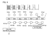
- FIG. 9 is an explanatory view illustrating a state where the failure retrieval device is connected to a conveyor device of another embodiment of the present invention, in which the abnormality alarm signal output from each zone controller is additionally illustrated.
- a conveyor device 1 according to an embodiment of the present invention will be described below.
- the conveyor device 1 includes a plurality of zone conveyors 2 ( 2 a , 2 b , 2 c , . . . ) arranged in series in a conveying direction.
- Each zone conveyor 2 ( 2 a , 2 b , 2 c , . . . ) is a conveying device which mainly includes conveying rollers 5 , a load presence sensor S (Sa, Sb, Sc, . . . ) and a zone controller 10 ( 10 a , 10 b , 10 c , . . . ). Since the zone conveyors 2 ( 2 a , 2 b , 2 c , 2 d . . . ) have the same mechanical configuration and the same size, a structure of the zone conveyor 2 b disposed in the center of the figure will be described in detail as a representative example.
- the zone conveyor 2 b is a device in which a plurality of conveying rollers 5 for conveying a conveying object are axially supported at predetermined interval in the conveying direction between a pair of left and right side frames 3 , 3 disposed in parallel.
- the conveying rollers 5 includes a freely rotatable follower roller 5 b and a motor-incorporated roller 5 a incorporating a drive motor 4 a (not illustrated in FIG. 2 ; see FIG. 3 ).
- there is only one motor-incorporated roller 5 a and all the remaining rollers are follower rollers 5 b.
- a transmission belt 6 is wound around two adjacent conveying rollers 5 in the zone conveyor 2 b . Therefore, a rotary drive force of the motor-incorporated roller 5 a can be transmitted to all the follower rollers 5 b .
- the motor-incorporated roller 5 a is disposed in a center portion.
- the load presence sensor Sb is provided in the zone conveyor 2 b .
- the load presence sensor Sb is provided on a side frame 3 .
- the load presence sensor Sb is positioned near a downstream side end.
- the load presence sensor Sb is a photoelectric sensor and has a light emitting element 20 such as a light-emitting diode or an infrared diode on an opposing side frame 3 .
- a light emitting element 20 such as a light-emitting diode or an infrared diode on an opposing side frame 3 .
- the load presence sensor Sb When a conveying object is present, light from the light-emitting element 20 is shielded by the conveying object, causing the load presence sensor Sb to output an ON (High level) signal; whereas when the conveying object is absent, the load presence sensor Sb outputs an OFF (Low level) signal.
- ON/OF of the photoelectric sensor allows detection of a state where the conveying object has been conveyed to a predetermined position.
- the zone controller 10 b for controlling drive of the drive motor 4 a (see FIG. 3 ) incorporated in the motor-incorporated roller 5 a is mounted to one side frame 3 of the zone conveyor 2 b .
- a known brushless motor is adopted for the drive motor 4 a.
- the zone controllers 10 ( 10 a , . . . 10 c , . . . 10 n ) provided in the two adjacent zone conveyors 2 ( 2 a , 2 b , 2 c , 2 d , . . . ) are connected to each other through a signal line 7 . Further, at least one (in the present embodiment, zone conveyor 2 a ) of the zone controllers 10 ( 10 a , . . . 10 n ) is connected to a host controller 50 through a signal line 8 .
- FIG. 4 illustrates in further detail an internal configuration and a connection state of each of the zone controllers 10 a to 10 n . Since the zone controllers 10 a to 10 n have the same configuration, a configuration of the zone controller 10 b will be described as a representative example.
- the zone controller 10 b receives a signal from the load presence sensor Sb of the corresponding zone. That is, the zone controller 10 b has a sensor signal input terminal 21 .
- the zone controller 10 b can transmit a light-emitting signal to the load presence sensor Sb and a pair of light emitting elements 20 . That is, the zone controller 10 b has a light-emitting element drive terminal 22 .
- the zone controller 10 b includes an arithmetic section 11 , a signal input section 12 , a signal transmission section 13 , a sensor drive circuit 14 , and a motor drive circuit 15 .
- the signal input section 12 is connected to a right-side input terminal 25 and a left-side input terminal 28 , individually processes a signal input from the right-side input terminal 25 and a signal input from the left-side input terminal 28 , and outputs the processed signal to the arithmetic section 11 .
- the signal input section 12 has a signal reception function to receive, in addition to a signal normally used for conveyance, an abnormality alarm signal from adjacent zone controllers 10 a and 10 c.
- the signal transmission section 13 is a circuit that transmits a signal output from the arithmetic section 11 to the outside, and is connected to a right-side output terminal 27 and a left-side output terminal 26 .
- the signal transmission section 13 has a processed signal transmission function to transmit, in addition to a signal normally used for conveyance, a signal processed by a signal processing function to the outside as an abnormality alarm signal.
- the arithmetic section 11 incorporates therein a normal conveyance program for smoothly conveying a conveying object and a program specific to the present embodiment.
- the conveyance program includes an arithmetic circuit configured by a ZPA controller that performs zero-pressure accumulation control (ZPA control).
- ZPA control is a control capable of avoiding collision between the conveying objects.
- the arithmetic section 11 refers to at least one of a signal input to the signal input section 12 and a signal output to the signal transmission section 13 to generate a control signal for driving the drive motor 4 a and transmits the generated control signal to the motor drive circuit 15 .
- the arithmetic section 11 performs an operation of receiving an external input signal such as a RUN/STOP signal from the host controller 50 and generating/transmitting a required control signal to the motor drive circuit 15 .
- the arithmetic section 11 has a node number storage memory (storage unit) that stores a node number (to be described in detail later).
- the signal to be referred to by the arithmetic section 11 is selectively set by a not illustrated switch. That is, in the present embodiment, the conveyance program can be switched between a simultaneous conveyance mode, a separating conveyance mode, and a conveyance prohibiting mode, and the signal to be referred to by the arithmetic section 11 is selected according to the setting. Descriptions of the above conveyance modes are omitted.
- the motor drive circuit 15 drives the drive motor 4 a while receiving the control signal from the arithmetic section 11 and a detection signal from a hall element (magnetic pole position detector, not illustrated) provided in the drive motor 4 a incorporated in the motor-incorporated roller 5 a.
- a hall element magnetic pole position detector, not illustrated
- a desired signal can be transmitted and received between the zone controllers 10 .
- the zone controller 10 receives, through the signal input section 12 , a load presence signal of the zone controller 10 (zone controller 10 a ) disposed adjacent thereto on an upstream side in the conveying direction of the conveying object, a load presence signal of the zone controller 10 (zone controller 10 c ) disposed adjacent thereto on a downstream side, and a drive state signal of the downstream side zone controller 10 .
- the load presence signal and drive state signal output from the arithmetic section 11 of the zone controller 10 b are transmitted to each of the other zone controllers 10 a and 10 c through the signal transmission section 13 .
- the load presence signal is a detection signal of the load presence sensors Sa to Sc (see FIGS. 1 and 3 ) provided in the respective control zones.
- each of the zone controllers 10 can refer to the load presence signals of the respective upstream and downstream side zone controllers and the drive state signal of the downstream side zone controller.
- a command signal from the host controller 50 is transmitted to a predetermined zone controller 10 (zone controller 10 a ) through the signal line 8 , and then transmitted from the predetermined zone controller 10 (zone controller 10 a ) to all the zone controllers constituting the conveyor device 1 (see FIG. 3 ).
- the zone controllers 10 exchange therebetween information on ON/OFF states of the load presence sensors S of adjacent zones and information on whether or not the drive motors 4 a of the adjacent zones are activated.
- the zone controller activates the drive motor 4 a of its corresponding zone when a predetermined condition, for example, that a conveying object is present in the corresponding zone and a conveying object is not present in a zone on the downstream side is satisfied, to convey the conveying object to the zone on the downstream side.
- the zone controller 10 of the present embodiment includes, in addition to the above program (conveyance program) for smoothly conveying a conveying object, a program (hereinafter, referred to as abnormality part detection program) for identifying a zone in which an abnormality has occurred.
- a program hereinafter, referred to as abnormality part detection program
- the abnormality part detection program includes an abnormality detection program (abnormality detection function), a signal creation program (signal creation function), and a signal processing program (signal processing function).
- the abnormality detection program (abnormality detection function) is a program that detects an abnormality that has occurred in the zone managed by itself.
- the abnormality may be arbitrarily determined and include, for example, disconnection of the drive motor 4 a , overcurrent of the drive motor 4 a , temperature abnormality of the drive motor 4 a , disconnection of the sensor, detection abnormality of the sensor, sensor noise, abnormality of the light-emitting element 20 , detection abnormality of a signal input from the zone controller 10 of another zone, signal transmission defect, supply voltage drop, and the like.
- the zone controller 10 b can detect an abnormality of the zone controller 10 itself.
- the signal creation program functions when an abnormality is detected by the abnormality detection program (abnormality detection function), and generates a pulse signal of a fixed time.
- the signal creation program (signal creation function) generates a pulse signal having a fixed time length (reference length) at a fixed period on the condition that an abnormality is detected by the abnormality detection program (abnormality detection function).
- a length of the pulse signal is sufficiently shorter than the pulse period, and is set to, e.g., a length less than 1/20, more desirably, a length less than 1/50 of the pulse period.
- the pulse length is desirably equal to or more than 1/100 of the pulse period.
- the pulse period is set to 6 seconds, and the length (reference length) of the pulse to be generated is set to 0.1 seconds. That is, the period of the pulse signal to be generated is 6 seconds. Of the 6 seconds, ON time is 0.1 seconds, and OFF time is 5.9 seconds.
- the pulse signal created by the signal creation program (signal creation function) is distinguished from other signals and serves as an abnormality alarm signal.
- the abnormality alarm signal is passed through the signal transmission section 13 and is output from one of the output terminals. In the present embodiment, out of the right-side output terminal 27 and the left-side output terminal 26 , the abnormality alarm signal is output from the left-side output terminal 26 .
- the signal processing program functions when the abnormality alarm signal is input to the zone controller 10 b from another zone controller 10 , and extends the width of the pulse signal as the abnormality alarm signal by a fixed time.
- the pulse width is extended up to a length obtained by adding the original pulse length (reference length). Specifically, the length of the input abnormality alarm signal is extended by 0.1 seconds.
- the abnormality alarm signal having a length of 0.1 seconds is input, 0.1 seconds are added thereto to create a pulse having a length of 0.2 seconds, and the resultant signal is output from the left-side output terminal 26 as a new abnormality alarm signal. More specifically, when a pulse signal having a period of 6 seconds in which ON time is 0.1 seconds and OFF time is 5.9 seconds is input, the width of the input pulse signal is increased, and a pulse signal in which ON time is 0.2 seconds and OFF time is 5.8 seconds is output.
- an abnormality alarm signal of 2.5 seconds is input, 0.1 seconds are added thereto to create a pulse having a length of 2.6 seconds, and the resultant signal is output from the left-side output terminal 26 as a new abnormality alarm signal.
- the conveyor device 1 of the present embodiment has a configuration in which the plurality of zone conveyors 2 a , 2 b , 2 c , 2 d , . . . are arranged in series in the conveying direction.
- a failure retrieval device 30 is connected to any zone conveyor 2 (in the present embodiment, zone conveyor 2 a ).
- the failure retrieval device 30 is connected to the zone controller 10 a of the zone conveyor 2 a positioned at the end of the conveyor device 1 .
- the failure retrieval device 30 is a device that receives the abnormality alarm signal output from the zone conveyor 2 and analyzes the received abnormality alarm signal.
- the abnormality alarm signal is output from the left-side output terminal 26 , so that the failure retrieval device 30 is connected to the left-side output terminal 26 of the zone controller 10 a.
- the failure retrieval device 30 detects the pulse length (pulse width) of the abnormality alarm signal and performs an arithmetic operation of dividing the detected pulse length by the reference length.
- the abnormality detection program (abnormality detection function) of the zone controller 10 f that manages the zone in which the abnormality has occurred detects an occurrence of the abnormality.
- a pulse signal having a period of 6 seconds and a reference pulse length of 0.1 seconds (a pulse signal having a period of 6 seconds in which ON time is 0.1 seconds and OFF time is 5.9 seconds) is generated by the function of the signal processing program (signal processing function), and the generated pulse signal is passed through the signal transmission section 13 and is output, as the abnormality alarm signal, from the left-side output terminal 26 (see FIG. 6 ).
- the left-side output terminal 26 of the zone conveyor 2 f is connected to the right-side input terminal 25 of the adjacent zone controller 10 e , so that the abnormality alarm signal having a pulse length of 0.1 seconds created by the zone controller 10 f as an abnormality generation source is input to the zone controller 10 e adjacently disposed to the left side in the figure.
- the signal processing program creates a pulse signal having a pulse length of 0.2 seconds (a pulse signal having a period of 6 seconds in which ON time is 0.2 seconds and OFF time is 5.8 seconds) by adding the reference length to the input pulse signal. Then, the pulse signal having a pulse length of 0.2 seconds is output from the left-side output terminal 26 of the zone controller 10 e as the abnormal alarm signal.
- the left-side output terminal 26 of the zone controller 10 e is connected to the right-side input terminal 25 of the adjacent zone controller 10 d , so that the abnormality alarm signal having a pulse length of 0.2 seconds created by the second zone controller 10 f is input to the zone controller 10 d adjacent to the left side in the figure, and the reference length is further added to create a pulse signal having a pulse length of 0.3 seconds (a pulse signal having a period of 6 seconds in which ON time is 0.3 seconds and OFF time is 5.7 seconds).
- the abnormality alarm signal having a pulse length of 0.3 seconds is input from the left-side output terminal 26 of the zone controller 10 d to the adjacent zone controller 10 c , and the reference length is further added to create a pulse signal having a pulse length of 0.4 seconds (having a period of 6 seconds in which ON time is 0.4 seconds and OFF time is 5.6 seconds).
- a pulse signal having a pulse length of 0.6 seconds (a pulse signal having a period of 6 seconds in which ON time is 0.6 seconds and OFF time is 5.4 seconds) is input from the zone controller 10 a at the end portion to the failure retrieval device 30 .
- the failure retrieval device 30 detects the length of the input pulse of the abnormality alarm signal, and performs an arithmetic operation of dividing the detected pulse length by the reference length.
- an arithmetic value is calculated.
- This arithmetic value coincides with the number of the zone controllers 10 , including the zone controller 10 f as the abnormality generation source, through which the pulse signal passes until it reaches the failure retrieval device 30 .
- the zone controller 10 f as the abnormality generation source is reached.
- the zone conveyor 2 f as the abnormality generation source can be identified.
- each zone controller 10 by inputting a pseudo abnormality alarm signal to a terminal end (most upstream side in the signal transmission direction) zone controller 10 g , it is possible to allow each zone controller 10 to store its node number. This operation is specifically described below.
- a pulse signal (the same pulse signal as the above-described abnormality alai in signal) having a pulse length of 0.1 seconds is input to the right-side input terminal 25 of the terminal end zone controller 10 g .
- a pseudo signal generation device is connected to the right-side input terminal 25 of the terminal end zone controller 10 g .
- a pulse signal having the reference pulse length is created in the pseudo signal generation device, and is input to the terminal end zone controller 10 g as a pseudo abnormality alarm signal.
- the terminal end zone controller 10 g determines the node number thereof in accordance with the pulse length of the input pulse signal, and stores the determined node number in the node number storage memory of the arithmetic section 11 (see FIG. 4 ). Since the pulse length of the pulse signal input to the zone controller 10 g is 0.1 seconds, “1” is stored as the node number.
- the signal processing program adds the reference length to the pulse length of the pulse signal. That is, in the zone controller 10 g , a pulse signal having a pulse length of 0.2 seconds (a pulse signal having a period of 6 seconds in which ON time is 0.2 seconds and OFF time is 5.8 seconds) is created. Then, this pulse signal having a pulse length of 0.2 seconds is input to the zone controller 10 f . That is, similarly to the abnormality alarm signal in the operation of detecting the zone conveyor 2 , the generated pseudo abnormality alarm signal is input to the adjacent zone controller 10 f.
- the zone controller 10 f to which the pulse signal having a pulse length of 0.2 seconds is input determines the node number thereof in accordance with the pulse length of the input pulse signal, and stores the determined node number in the node number storage memory of the arithmetic section 11 . Since the pulse length of the pulse signal input to the zone controller 10 f is 0.2 seconds, “2” is stored as the node number.
- each zone controller 10 has a node number calculation function of calculating the node number from the pulse length of the input pulse signal. Then, the zone controller 10 performs operations of calculating the node number from the input pulse signal, storing the node number, processing the pulse signal, and outputting the processed pulse signal to the adjacent zone controller 10 (or failure retrieval device 30 ). Note that the processing of the pulse signal and the output of the processed pulse signal are performed in the same manner as those in the operation of detecting the zone conveyor 2 as the abnormality generation source.
- the node number is sequentially given to each zone controller 10 and the node number is stored in each zone controller 10 .
- the command signal from the host controller 50 is transmitted to a predetermined zone controller 10 (zone controller 10 a ) through the signal line 8 , and is then transmitted from the predetermined zone controller 10 (zone controller 10 a ) to all the zone controllers constituting the conveyor device 1 (see FIG. 3 ).
- the output signals are output from the predetermined zone controller 10 (zone controller 10 a ) to the adjacent zone controller 10 (zone controller 10 b ), and are thereafter successively output to the adjacent zone controllers 10 .
- each zone controller 10 identifies whether or not the signal indicating the node number output together with the command signal indicates the node number of the zone controller 10 itself.
- the zone controller 10 When the node number coincides with the node number of the zone controller 10 itself, the zone controller 10 performs an operation instructed by the command signal, whereas when the node number does not coincide with the node number of the zone controller itself, the zone controller 10 does not perform an operation instructed by the transmitted command signal but outputs the input signal to the adjacent zone controller 10 as it is. That is, when the conveyor device 1 is operated in a state where the node number is stored in each zone controller 10 , it is necessary for only the predetermined zone controller 10 to perform the operation instructed by the command signal output from the host controller 50 , eliminating the need for all the zone controllers 10 to analyze the command signal. This facilitates signal exchange between the host controller 50 and the predetermined zone controller 10 of the plurality of zone controllers 10 .
- each zone controller 10 simply outputting the command signal from the host controller 50 allows only a predetermined zone controller 10 to perform an operation of changing a motor speed provided in the zone managed by the predetermined zone controller 10 itself. Further, it is possible to allow only a predetermined zone controller 10 to change a conveying speed setting (slow start setting) in the zone conveyor 2 managed by the predetermined zone controller 10 itself. Furthermore, it is possible to allow only a predetermined zone controller 10 to perform program rewriting.
- the conveyor device 1 when the conveyor device 1 is operated in a state where the node number is stored in each zone controller 10 , it is also possible to facilitate identification of the zone conveyor 2 f as the abnormality generation source upon occurrence of any abnormality in the conveyor device 1 .
- the zone controller 10 when an abnormality occurs, and the abnormality detection program of a zone controller 10 that manages the zone in which the abnormality occurs detects the occurrence of the abnormality, the zone controller 10 outputs a signal indicating the node number (or relevant information for identifying the node number) stored in the zone controller 10 itself and the abnormality alarm signal. At this time, another zone controller 10 outputs the input signals to the adjacent zone controller 10 (or failure retrieval device 30 ) as it is.
- the signals transmitted from the zone controller 10 in which the abnormality occurs are output to the failure retrieval device 30 as it is after passing through another zone controller as needed. Since the signal indicating the node number (or relevant information for identifying the node number) is included in the transmitted signal, the failure retrieval device 30 can identify the zone controller 10 of the zone in which the abnormality has occurred. That is, with a configuration in which the conveyor device 1 is operated in a state where the node number is previously stored in each zone controller 10 , it is possible to identify the zone controller 10 of the zone in which the abnormality has occurred without execution of processing for the abnormality alarm signal in each zone controller 10 .
- the pseudo signal generation device is connected to the zone controller 10 , and the pseudo abnormality alarm signal is output from the pseudo signal generation device to the terminal end zone controller 10 g to make each zone controller 10 store its node number.
- the present invention is not limited thereto.
- a configuration may be adopted, in which any of the zone controller 10 outputs the pseudo abnormality alarm signal to make each zone controller store its node number.
- a timing at which each zone controller is made to store its node number is not limited to the test run time.
- the operation of making each zone controller store its node number may be automatically performed when the conveyor device 1 is powered ON.
- the failure retrieval device 30 is connected to the zone controller 10 a at the end portion so as to retrieve the failure part.
- the failure retrieval device 30 may be connected to any position as long as it is located on the downstream side of the failure part in the signal transmission direction. For example, as illustrated in FIG. 8 , when the failure retrieval device 30 is connected to the zone controller 10 c , a pulse signal having a pulse length of 0.4 seconds is input to the failure retrieval device 30 and, thus, the failure retrieval device 30 can identify the failure part.
- the pulse length is increased.
- the number of pulses to be generated may be increased.
- the signal processing program may be configured to add, when the abnormality alarm signal is input from another zone controller, a pulse having a predetermined length (e.g., reference length of 0.1 seconds) to the abnormality alarm signal.
- a pulse having a predetermined length e.g., reference length of 0.1 seconds
- the number of pulses is increased by one every time the abnormality alarm signal passes through the zone controller.
- the pulse length or the number of pulses may be reduced every time the abnormality alai in signal passes through the zone controller.
- the signal processing function may be a function that processes the pulse signal based on a function following a fixed rule.
- one zone conveyor 2 is controlled by one zone controller 10 .
- the conveyor device of the present invention is not limited thereto.
- the conveyor device may be adopted in which a plurality of the zone conveyors may be controlled by one zone controller. Also in this case, by identifying the zone controller that manages the zone conveyor in the zone in which the failure has occurred, it is possible to identify the failure part in the conveyor device.
- a roller conveyor is adopted as the zone conveyor 2 .
- the conveyor device of the present invention is not limited thereto.
- a belt conveyor may be adopted as the zone conveyor.
Applications Claiming Priority (3)
| Application Number | Priority Date | Filing Date | Title |
|---|---|---|---|
| JP2012-062182 | 2012-03-19 | ||
| JP2012062182 | 2012-03-19 | ||
| PCT/JP2013/056692 WO2013141066A1 (ja) | 2012-03-19 | 2013-03-11 | ゾーンコントローラ、並びに、コンベア装置 |
Publications (2)
| Publication Number | Publication Date |
|---|---|
| US20150068871A1 US20150068871A1 (en) | 2015-03-12 |
| US9446907B2 true US9446907B2 (en) | 2016-09-20 |
Family
ID=49222526
Family Applications (1)
| Application Number | Title | Priority Date | Filing Date |
|---|---|---|---|
| US14/386,180 Active US9446907B2 (en) | 2012-03-19 | 2013-03-11 | Zone controller and conveyor device |
Country Status (4)
| Country | Link |
|---|---|
| US (1) | US9446907B2 (ja) |
| EP (1) | EP2829496B1 (ja) |
| JP (1) | JP6142231B2 (ja) |
| WO (1) | WO2013141066A1 (ja) |
Cited By (2)
| Publication number | Priority date | Publication date | Assignee | Title |
|---|---|---|---|---|
| US10322883B2 (en) * | 2014-11-18 | 2019-06-18 | Itoh Denki Co. | Conveyor device, conveyor system, zone controller, CAD device, and method for manufacturing conveyor device |
| WO2022226645A1 (en) * | 2021-04-27 | 2022-11-03 | Stephenson Technologies Inc. | System for controlling a vehicle conveyor, and a vehicle wash having the same |
Families Citing this family (8)
| Publication number | Priority date | Publication date | Assignee | Title |
|---|---|---|---|---|
| JP6217491B2 (ja) * | 2014-03-27 | 2017-10-25 | 村田機械株式会社 | 搬送制御システム及びデータ処理装置 |
| US10222775B2 (en) | 2015-11-30 | 2019-03-05 | Hubbell Incorporated | Interrupt exception window protocol on a data communication bus and methods and apparatuses for using same |
| US10341135B2 (en) * | 2015-12-30 | 2019-07-02 | Nova-Tron Controls Corp. | Zone control system for conveyor system |
| JP7197508B2 (ja) * | 2017-05-19 | 2022-12-27 | スパン テック エルエルシー | 調節可能なコンベヤベルトガイドレールおよび関連方法 |
| US10889451B2 (en) * | 2018-10-17 | 2021-01-12 | Intelligrated Headquarters, Llc | System and method for controlling an accumulation conveyor |
| WO2020203477A1 (ja) * | 2019-04-05 | 2020-10-08 | 伊東電機株式会社 | コンベヤシステム、原因情報報知装置、原因情報報知装置用のプログラム、及び原因情報報知装置用のプログラムを記録したコンピュータ読み取り可能な記録媒体 |
| JP7149607B2 (ja) * | 2019-10-25 | 2022-10-07 | 伊東電機株式会社 | コンベヤシステム |
| CN116915821B (zh) * | 2023-07-25 | 2024-03-12 | 河南省通信建设管理咨询有限公司 | 一种基于5g的工程管理平台 |
Citations (13)
| Publication number | Priority date | Publication date | Assignee | Title |
|---|---|---|---|---|
| JPH0281817A (ja) | 1988-09-16 | 1990-03-22 | Daifuku Co Ltd | 仕分け設備 |
| AU634261B2 (en) | 1989-08-09 | 1993-02-18 | Tasman Cable Company Pty. Limited (Tcc) | Fault location arrangement for digital transmission system |
| JP2002356220A (ja) | 2001-03-28 | 2002-12-10 | Hitachi Ltd | ローラコンベアシステム |
| JP2004026503A (ja) | 2002-05-08 | 2004-01-29 | Ito Denki Kk | 搬送装置 |
| US20040166911A1 (en) | 2003-02-21 | 2004-08-26 | Chen Shui Jung | Pulse data coding method for wireless signal transmitting and receiving devices |
| US20040182684A1 (en) * | 2003-03-19 | 2004-09-23 | Cavanna S.P.A. | Device for conveying products, particularly for automatic packaging machinery, and corresponding method of use |
| JP2004307219A (ja) | 2004-07-26 | 2004-11-04 | Ito Denki Kk | コンベアシステムの制御装置並びに方法、及び、コンベアシステムのモニタリング装置 |
| US6827202B2 (en) * | 2001-12-21 | 2004-12-07 | Balluff, Inc. | Methods and apparatus for controlling conveyor zones |
| JP2005119752A (ja) | 2001-06-20 | 2005-05-12 | Ito Denki Kk | ゾーンコントローラ、コントローラ、並びに、コンベアシステム |
| JP2005231745A (ja) | 2001-06-27 | 2005-09-02 | Ito Denki Kk | ゾーンコントローラ |
| US20050262363A1 (en) | 2004-05-19 | 2005-11-24 | George Claseman | Method for signaling during a transaction and receiving unit and system for use therewith |
| EP2159655A2 (en) | 2008-08-28 | 2010-03-03 | Anywire Corporation Ltd. | Conveyance Control System and Conveyance Control Method |
| US8042681B2 (en) * | 2008-10-30 | 2011-10-25 | Worldwide Logistics Corporation | Drive roller controller for an accumulating conveyor system |
-
2013
- 2013-03-11 JP JP2014506147A patent/JP6142231B2/ja active Active
- 2013-03-11 EP EP13764466.2A patent/EP2829496B1/en active Active
- 2013-03-11 US US14/386,180 patent/US9446907B2/en active Active
- 2013-03-11 WO PCT/JP2013/056692 patent/WO2013141066A1/ja active Application Filing
Patent Citations (13)
| Publication number | Priority date | Publication date | Assignee | Title |
|---|---|---|---|---|
| JPH0281817A (ja) | 1988-09-16 | 1990-03-22 | Daifuku Co Ltd | 仕分け設備 |
| AU634261B2 (en) | 1989-08-09 | 1993-02-18 | Tasman Cable Company Pty. Limited (Tcc) | Fault location arrangement for digital transmission system |
| JP2002356220A (ja) | 2001-03-28 | 2002-12-10 | Hitachi Ltd | ローラコンベアシステム |
| JP2005119752A (ja) | 2001-06-20 | 2005-05-12 | Ito Denki Kk | ゾーンコントローラ、コントローラ、並びに、コンベアシステム |
| JP2005231745A (ja) | 2001-06-27 | 2005-09-02 | Ito Denki Kk | ゾーンコントローラ |
| US6827202B2 (en) * | 2001-12-21 | 2004-12-07 | Balluff, Inc. | Methods and apparatus for controlling conveyor zones |
| JP2004026503A (ja) | 2002-05-08 | 2004-01-29 | Ito Denki Kk | 搬送装置 |
| US20040166911A1 (en) | 2003-02-21 | 2004-08-26 | Chen Shui Jung | Pulse data coding method for wireless signal transmitting and receiving devices |
| US20040182684A1 (en) * | 2003-03-19 | 2004-09-23 | Cavanna S.P.A. | Device for conveying products, particularly for automatic packaging machinery, and corresponding method of use |
| US20050262363A1 (en) | 2004-05-19 | 2005-11-24 | George Claseman | Method for signaling during a transaction and receiving unit and system for use therewith |
| JP2004307219A (ja) | 2004-07-26 | 2004-11-04 | Ito Denki Kk | コンベアシステムの制御装置並びに方法、及び、コンベアシステムのモニタリング装置 |
| EP2159655A2 (en) | 2008-08-28 | 2010-03-03 | Anywire Corporation Ltd. | Conveyance Control System and Conveyance Control Method |
| US8042681B2 (en) * | 2008-10-30 | 2011-10-25 | Worldwide Logistics Corporation | Drive roller controller for an accumulating conveyor system |
Non-Patent Citations (2)
| Title |
|---|
| International Preliminary Report on Patentability and Written Opinion, PCT/JP2013/056692, Sep. 23, 2014. |
| Supplementary European Search Report, dated Dec. 1, 2015, in European Patent Appln. No. EP 13 76 4466. |
Cited By (2)
| Publication number | Priority date | Publication date | Assignee | Title |
|---|---|---|---|---|
| US10322883B2 (en) * | 2014-11-18 | 2019-06-18 | Itoh Denki Co. | Conveyor device, conveyor system, zone controller, CAD device, and method for manufacturing conveyor device |
| WO2022226645A1 (en) * | 2021-04-27 | 2022-11-03 | Stephenson Technologies Inc. | System for controlling a vehicle conveyor, and a vehicle wash having the same |
Also Published As
| Publication number | Publication date |
|---|---|
| US20150068871A1 (en) | 2015-03-12 |
| EP2829496B1 (en) | 2021-05-26 |
| EP2829496A4 (en) | 2016-01-06 |
| EP2829496A1 (en) | 2015-01-28 |
| JPWO2013141066A1 (ja) | 2015-08-03 |
| JP6142231B2 (ja) | 2017-06-07 |
| WO2013141066A1 (ja) | 2013-09-26 |
Similar Documents
| Publication | Publication Date | Title |
|---|---|---|
| US9446907B2 (en) | Zone controller and conveyor device | |
| JP6669776B2 (ja) | ハードウェア検出を備えたコンベヤの制御ユニット | |
| JP6563033B2 (ja) | 搬送装置の設置方法 | |
| JP4122392B2 (ja) | ゾーンコントローラ | |
| CN105189318B (zh) | 辊式输送装置、控制器和机械装置的异常检测方法 | |
| JP6796598B2 (ja) | 搬送装置における制御ユニットを交換する方法 | |
| EP2933662B2 (en) | Multiple optical axis photoelectric sensor | |
| KR101215430B1 (ko) | 운송제어 시스템 및 운송제어 방법 | |
| WO2013191217A1 (ja) | コンベア装置及びコンベア装置による重量検知方法 | |
| JP2013199359A (ja) | コンベア装置、並びに、ゾーンコントローラ | |
| US11365088B2 (en) | Monitoring device for a passenger transport system, testing method and passenger transport system | |
| WO2017050690A1 (en) | Hoistway communication system | |
| JP2012211015A (ja) | コンベア装置、集合型ゾーンコントローラ、並びにゾーンコントローラ | |
| US20220024697A1 (en) | Conveyor System, Cause Information Report Device, and Computer-Readable Recording Medium Recording Program for Cause Information Report Device | |
| JP6211230B2 (ja) | 搬送システム | |
| US20230382654A1 (en) | Non-plc-based conveyor controller | |
| JP3546832B2 (ja) | ゾーン制御方式コンベアシステム、並びに、信号割込装置 | |
| KR20080082325A (ko) | 이송 컨베이어의 개별 제어시스템 | |
| US20210286052A1 (en) | Photoelectric Sensor and Light Emitter | |
| JP6444291B2 (ja) | ディジタル信号入出力装置 | |
| JPH08143133A (ja) | 移送装置制御方法および移送装置 | |
| JP2021131306A (ja) | 検査システム及びそれに用いられる発光コントローラ | |
| EP2674823A1 (en) | Emergency management system |
Legal Events
| Date | Code | Title | Description |
|---|---|---|---|
| AS | Assignment |
Owner name: ITOH DENKI CO., LTD., JAPAN Free format text: ASSIGNMENT OF ASSIGNORS INTEREST;ASSIGNORS:TACHIBANA, TOSHIYUKI;FUKATA, SHIGEKI;ENOKI, TOSHIMASA;REEL/FRAME:033961/0048 Effective date: 20140918 |
|
| STCF | Information on status: patent grant |
Free format text: PATENTED CASE |
|
| MAFP | Maintenance fee payment |
Free format text: PAYMENT OF MAINTENANCE FEE, 4TH YR, SMALL ENTITY (ORIGINAL EVENT CODE: M2551); ENTITY STATUS OF PATENT OWNER: SMALL ENTITY Year of fee payment: 4 |
|
| MAFP | Maintenance fee payment |
Free format text: PAYMENT OF MAINTENANCE FEE, 8TH YR, SMALL ENTITY (ORIGINAL EVENT CODE: M2552); ENTITY STATUS OF PATENT OWNER: SMALL ENTITY Year of fee payment: 8 |