US9440793B2 - Conveyor device for conveying food - Google Patents
Conveyor device for conveying food Download PDFInfo
- Publication number
- US9440793B2 US9440793B2 US14/758,062 US201314758062A US9440793B2 US 9440793 B2 US9440793 B2 US 9440793B2 US 201314758062 A US201314758062 A US 201314758062A US 9440793 B2 US9440793 B2 US 9440793B2
- Authority
- US
- United States
- Prior art keywords
- path
- conveyor belt
- spiral
- guide rail
- disposed
- Prior art date
- Legal status (The legal status is an assumption and is not a legal conclusion. Google has not performed a legal analysis and makes no representation as to the accuracy of the status listed.)
- Active
Links
- 230000008878 coupling Effects 0.000 claims abstract description 29
- 238000010168 coupling process Methods 0.000 claims abstract description 29
- 238000005859 coupling reaction Methods 0.000 claims abstract description 29
- 239000011347 resin Substances 0.000 claims abstract description 23
- 229920005989 resin Polymers 0.000 claims abstract description 23
- 230000001174 ascending effect Effects 0.000 claims description 30
- 230000007246 mechanism Effects 0.000 claims description 30
- 230000000903 blocking effect Effects 0.000 claims description 4
- 238000000034 method Methods 0.000 claims description 2
- 230000008569 process Effects 0.000 claims description 2
- 239000002184 metal Substances 0.000 abstract description 9
- 239000000843 powder Substances 0.000 abstract description 9
- 238000004519 manufacturing process Methods 0.000 abstract description 4
- 238000001514 detection method Methods 0.000 description 11
- 238000007710 freezing Methods 0.000 description 5
- 230000008014 freezing Effects 0.000 description 5
- 239000000463 material Substances 0.000 description 5
- 229910001220 stainless steel Inorganic materials 0.000 description 4
- 239000010935 stainless steel Substances 0.000 description 4
- 230000002411 adverse Effects 0.000 description 3
- 230000005540 biological transmission Effects 0.000 description 3
- 238000001035 drying Methods 0.000 description 3
- 238000010438 heat treatment Methods 0.000 description 3
- 239000004696 Poly ether ether ketone Substances 0.000 description 2
- 239000004952 Polyamide Substances 0.000 description 2
- 238000005299 abrasion Methods 0.000 description 2
- 230000008859 change Effects 0.000 description 2
- 238000010586 diagram Methods 0.000 description 2
- 229920002647 polyamide Polymers 0.000 description 2
- 229920002530 polyetherether ketone Polymers 0.000 description 2
- 239000004677 Nylon Substances 0.000 description 1
- 239000004809 Teflon Substances 0.000 description 1
- 229920006362 Teflon® Polymers 0.000 description 1
- 230000002159 abnormal effect Effects 0.000 description 1
- 230000005856 abnormality Effects 0.000 description 1
- 238000005452 bending Methods 0.000 description 1
- 230000008901 benefit Effects 0.000 description 1
- 238000007796 conventional method Methods 0.000 description 1
- 238000001816 cooling Methods 0.000 description 1
- 230000000593 degrading effect Effects 0.000 description 1
- 238000006073 displacement reaction Methods 0.000 description 1
- 239000000428 dust Substances 0.000 description 1
- 230000000694 effects Effects 0.000 description 1
- 229920006351 engineering plastic Polymers 0.000 description 1
- 230000002349 favourable effect Effects 0.000 description 1
- NBVXSUQYWXRMNV-UHFFFAOYSA-N fluoromethane Chemical compound FC NBVXSUQYWXRMNV-UHFFFAOYSA-N 0.000 description 1
- 238000009434 installation Methods 0.000 description 1
- 229920001778 nylon Polymers 0.000 description 1
- 239000004417 polycarbonate Substances 0.000 description 1
- 229920000515 polycarbonate Polymers 0.000 description 1
- 230000001360 synchronised effect Effects 0.000 description 1
Images


Classifications
-
- B—PERFORMING OPERATIONS; TRANSPORTING
- B65—CONVEYING; PACKING; STORING; HANDLING THIN OR FILAMENTARY MATERIAL
- B65G—TRANSPORT OR STORAGE DEVICES, e.g. CONVEYORS FOR LOADING OR TIPPING, SHOP CONVEYOR SYSTEMS OR PNEUMATIC TUBE CONVEYORS
- B65G21/00—Supporting or protective framework or housings for endless load-carriers or traction elements of belt or chain conveyors
- B65G21/16—Supporting or protective framework or housings for endless load-carriers or traction elements of belt or chain conveyors for conveyors having endless load-carriers movable in curved paths
- B65G21/18—Supporting or protective framework or housings for endless load-carriers or traction elements of belt or chain conveyors for conveyors having endless load-carriers movable in curved paths in three-dimensionally curved paths
-
- A—HUMAN NECESSITIES
- A23—FOODS OR FOODSTUFFS; TREATMENT THEREOF, NOT COVERED BY OTHER CLASSES
- A23L—FOODS, FOODSTUFFS, OR NON-ALCOHOLIC BEVERAGES, NOT COVERED BY SUBCLASSES A21D OR A23B-A23J; THEIR PREPARATION OR TREATMENT, e.g. COOKING, MODIFICATION OF NUTRITIVE QUALITIES, PHYSICAL TREATMENT; PRESERVATION OF FOODS OR FOODSTUFFS, IN GENERAL
- A23L3/00—Preservation of foods or foodstuffs, in general, e.g. pasteurising, sterilising, specially adapted for foods or foodstuffs
- A23L3/02—Preservation of foods or foodstuffs, in general, e.g. pasteurising, sterilising, specially adapted for foods or foodstuffs by heating materials in packages which are progressively transported, continuously or stepwise, through the apparatus
- A23L3/06—Preservation of foods or foodstuffs, in general, e.g. pasteurising, sterilising, specially adapted for foods or foodstuffs by heating materials in packages which are progressively transported, continuously or stepwise, through the apparatus with packages transported along a helical path
-
- A—HUMAN NECESSITIES
- A23—FOODS OR FOODSTUFFS; TREATMENT THEREOF, NOT COVERED BY OTHER CLASSES
- A23L—FOODS, FOODSTUFFS, OR NON-ALCOHOLIC BEVERAGES, NOT COVERED BY SUBCLASSES A21D OR A23B-A23J; THEIR PREPARATION OR TREATMENT, e.g. COOKING, MODIFICATION OF NUTRITIVE QUALITIES, PHYSICAL TREATMENT; PRESERVATION OF FOODS OR FOODSTUFFS, IN GENERAL
- A23L3/00—Preservation of foods or foodstuffs, in general, e.g. pasteurising, sterilising, specially adapted for foods or foodstuffs
- A23L3/36—Freezing; Subsequent thawing; Cooling
- A23L3/361—Freezing; Subsequent thawing; Cooling the materials being transported through or in the apparatus, with or without shaping, e.g. in form of powder, granules, or flakes
-
- B—PERFORMING OPERATIONS; TRANSPORTING
- B65—CONVEYING; PACKING; STORING; HANDLING THIN OR FILAMENTARY MATERIAL
- B65G—TRANSPORT OR STORAGE DEVICES, e.g. CONVEYORS FOR LOADING OR TIPPING, SHOP CONVEYOR SYSTEMS OR PNEUMATIC TUBE CONVEYORS
- B65G17/00—Conveyors having an endless traction element, e.g. a chain, transmitting movement to a continuous or substantially-continuous load-carrying surface or to a series of individual load-carriers; Endless-chain conveyors in which the chains form the load-carrying surface
- B65G17/06—Conveyors having an endless traction element, e.g. a chain, transmitting movement to a continuous or substantially-continuous load-carrying surface or to a series of individual load-carriers; Endless-chain conveyors in which the chains form the load-carrying surface having a load-carrying surface formed by a series of interconnected, e.g. longitudinal, links, plates, or platforms
- B65G17/063—Conveyors having an endless traction element, e.g. a chain, transmitting movement to a continuous or substantially-continuous load-carrying surface or to a series of individual load-carriers; Endless-chain conveyors in which the chains form the load-carrying surface having a load-carrying surface formed by a series of interconnected, e.g. longitudinal, links, plates, or platforms the load carrying surface being formed by profiles, rods, bars, rollers or the like attached to more than one traction element
-
- B—PERFORMING OPERATIONS; TRANSPORTING
- B65—CONVEYING; PACKING; STORING; HANDLING THIN OR FILAMENTARY MATERIAL
- B65G—TRANSPORT OR STORAGE DEVICES, e.g. CONVEYORS FOR LOADING OR TIPPING, SHOP CONVEYOR SYSTEMS OR PNEUMATIC TUBE CONVEYORS
- B65G17/00—Conveyors having an endless traction element, e.g. a chain, transmitting movement to a continuous or substantially-continuous load-carrying surface or to a series of individual load-carriers; Endless-chain conveyors in which the chains form the load-carrying surface
- B65G17/06—Conveyors having an endless traction element, e.g. a chain, transmitting movement to a continuous or substantially-continuous load-carrying surface or to a series of individual load-carriers; Endless-chain conveyors in which the chains form the load-carrying surface having a load-carrying surface formed by a series of interconnected, e.g. longitudinal, links, plates, or platforms
- B65G17/08—Conveyors having an endless traction element, e.g. a chain, transmitting movement to a continuous or substantially-continuous load-carrying surface or to a series of individual load-carriers; Endless-chain conveyors in which the chains form the load-carrying surface having a load-carrying surface formed by a series of interconnected, e.g. longitudinal, links, plates, or platforms the surface being formed by the traction element
- B65G17/086—Conveyors having an endless traction element, e.g. a chain, transmitting movement to a continuous or substantially-continuous load-carrying surface or to a series of individual load-carriers; Endless-chain conveyors in which the chains form the load-carrying surface having a load-carrying surface formed by a series of interconnected, e.g. longitudinal, links, plates, or platforms the surface being formed by the traction element specially adapted to follow a curved path
-
- B—PERFORMING OPERATIONS; TRANSPORTING
- B65—CONVEYING; PACKING; STORING; HANDLING THIN OR FILAMENTARY MATERIAL
- B65G—TRANSPORT OR STORAGE DEVICES, e.g. CONVEYORS FOR LOADING OR TIPPING, SHOP CONVEYOR SYSTEMS OR PNEUMATIC TUBE CONVEYORS
- B65G23/00—Driving gear for endless conveyors; Belt- or chain-tensioning arrangements
- B65G23/02—Belt- or chain-engaging elements
- B65G23/04—Drums, rollers, or wheels
- B65G23/06—Drums, rollers, or wheels with projections engaging abutments on belts or chains, e.g. sprocket wheels
-
- A—HUMAN NECESSITIES
- A23—FOODS OR FOODSTUFFS; TREATMENT THEREOF, NOT COVERED BY OTHER CLASSES
- A23V—INDEXING SCHEME RELATING TO FOODS, FOODSTUFFS OR NON-ALCOHOLIC BEVERAGES AND LACTIC OR PROPIONIC ACID BACTERIA USED IN FOODSTUFFS OR FOOD PREPARATION
- A23V2002/00—Food compositions, function of food ingredients or processes for food or foodstuffs
Definitions
- the present invention relates to a conveyor device for conveying food which can be applied to food processing in a closed space and more particularly can be applied to processing such as cooling, freezing, heating, and drying.
- Patent Document 1 discloses an example of such a conveyor device which is schematically described below with reference to FIG. 14 .
- a spiral endless conveyor device 100 has a spiral endless conveyor belt 104 disposed in a vertical direction in an area surrounded by a plurality of columns 102 .
- An electric motor 106 is disposed in an area around an inlet of the spiral endless conveyor 104 and an auxiliary transmission device 108 is disposed in an interior area of the spiral endless conveyor belt 104 .
- the electric motor 106 drivingly rotates the auxiliary transmission device 108 via a gear 110 .
- a plurality of columns 112 forming the auxiliary transmission device 108 , rotate to apply moving force to the spiral endless conveyor belt 104 .
- the spiral endless conveyor belt 104 includes an inlet path 104 A, a spiral ascending path 104 B disposed in an interior area of the columns 102 , a turning back path 104 C disposed at the upper most portion, a spiral descending path 104 D, and an outlet path 104 E.
- the upper most portion of the spiral ascending path 104 B is connected to the upper most portion of the spiral descending path 104 D via the turning back path 104 C.
- the turning back path 104 C does not involve reversing of the conveyance surface, and turns back with the same conveyance surface always facing upward.
- the spiral ascending path 104 B and the spiral descending path 104 D are alternately arranged in the vertical direction and move in opposite directions.
- Patent Document 2 and Patent Document 3 disclose a configuration of a conveyor belt forming a conveyor device.
- a configuration is disclosed which includes tooth-shaped portions, of an involute form, arranged at an equal interval at an outer side portion of the conveyor belt and a toothed wheel which meshes with the tooth-shaped portions, and which drives the conveyor belt with the toothed wheel.
- Patent Document 3 discloses a configuration in which supported portions, with a U-shaped cross section opening in the horizontal direction, are disposed at both side portions of the conveyor belt and a guide rail loosely fitted to the supported portions is provided, and the guide rail movably supports the conveyor belt.
- Patent Document 2 and 3 disclose a configuration in which an anti-drop plate, which prevents a conveyed product from dropping, protrudes upward from a conveyor belt conveyance surface and is fixedly fitted to two adjacent bars forming the conveyor belt.
- Patent Document 1 Japanese Patent Application Laid-open No. 2007-169059
- Patent Document 2 Japanese Patent Application Laid-open No. 2008-56489 (FIG. 6)
- Patent Document 3 Japanese Utility Model No. 3123226
- the tooth-shaped portions and the tooth-wheel which meshes with the tooth-shaped portions, disclosed in Patent Document 2 are formed of metal such as stainless steel.
- metal powder produced by friction at the meshing portion, might adversely affect the quality of a conveyed product such as food.
- the supported portions having the U-shaped cross section disclosed in Patent Document 3 have the following problems. Specifically, in a low temperature environment such as a freezer, the rail might protrude inward from each of the supported portions due to the difference between a material of the supported portion and a material of the rail supporting the supported portion in a linear expansion coefficient.
- the anti-drop plate disclosed in Patent Documents 2 and 3 is a single anti-drop plate fixedly fitted to the two bars forming the conveyor belt.
- the relative position between the adjacent bars is restricted.
- an intricate curved line shape of the conveyor belt cannot be formed at a curved portion of the conveyor belt.
- the anti-drop plate has fixedly fitted portions for the two bars formed, and thus has a complicated structure and requires a high manufacturing cost.
- an object of the present invention is to prevent the production of the metal powder, and prevent the contact pressure and wearing from increasing at the slide portion between the conveyor belt and the guide rail in the low temperature environment.
- a furthermore object is to enable the slackening of the conveyor belt to be easily fixed, achieve higher design freedom of the conveyor belt by enabling the intricate curved line shape to be formed at the curved portion of the conveyor belt, and simplify the structure of the anti-drop material.
- the present invention is applied to a conveyor device for conveying food which processes food while conveying the food with a spiral conveyor belt disposed in a vertical direction in a closed space and includes a large number of bar members which are arranged in parallel to form the conveyor belt, coupling members which are fixed to both ends of each of the bar members and couple the bar members with each other, a guide rail which slidably supports the conveyor belt including the bar members, and a sprocket which meshes with tooth-shaped portions formed on the coupling members.
- the conveyor device for conveying food includes a slide block fixed to a portion of each bar member at an inner side of one of the coupling members and configured to slide on the guide rail disposed along the conveyor belt, and rollers which form the tooth-shaped portions and mesh with the sprocket, the rollers being rotatably supported by shafts disposed on the coupling members in a direction intersecting with a conveyance surface of the conveyor belt.
- the rollers each include a wear resistant resin member, and a meshing portion of the sprocket which meshes with the rollers includes a wear resistant resin member.
- the guide rail supports the conveyor belt from below via the slide blocks.
- the sprocket applies driving force to move the coupling members in a conveyance direction, the slide block slides on the guide rail while being supported by the guide rail, and the conveyor belt moves in the conveyance direction.
- the rollers can rotate in a rotation direction of the sprocket, whereby slipping between the roller and the sprocket can be reduced.
- the roller and the meshing portion of the sprocket include wear resistant resin, whereby wearing at the meshing portion can be reduced.
- the quality of the food can be prevented from being adversely affected.
- the wear resistant resin used in the present invention is, for example, what is known as engineering plastic such as ultrahigh molecular polycarbonate (PC), polyamide (PA), and polyether ether ketone (PEEK), fluorocarbon resin such as Teflon (registered trademark), nylon resin, or the like.
- engineering plastic such as ultrahigh molecular polycarbonate (PC), polyamide (PA), and polyether ether ketone (PEEK)
- fluorocarbon resin such as Teflon (registered trademark), nylon resin, or the like.
- the slide block has the slide surface which slides on the guide rail and does not surround the rail, as in the case of the supported portion in Patent Document 3.
- the slide block is provided for each bar member, and thus the movement of the adjacent bar members is not restricted by the slide block at a curved portion of the conveyor belt.
- the bar member can form an intricate curved line shape at the curved portion of the conveyor belt, and thus higher design freedom of the conveyor belt can be achieved.
- the slide block can have a simple shape and can be manufactured at a low cost.
- each coupling member has a bent shape with an interior space, has both end portions coupled to a first bar member, and has a pair of slotted holes in which a second bar member which is adjacent to the first bar member is loosely fitted.
- the conveyor belt can be formed with the coupling members provided at both ends of each bar member restricting the two adjacent bar members.
- the coupling members are restricted in series along the conveyance path via the bar members.
- the bar member loosely fitted in the slotted holes of the coupling members can move in the conveyance direction in the slotted holes.
- Curving of the conveyor belt can be achieved by changing the interval between both ends of the bar members.
- each slide block includes: a slide surface which is in slidable contact with the guide rail, and a guide portion which protrudes towards the guide rail from the slide surface and has a guide surface guided by a side surface of the guide rail, and the guide rail supports the spiral conveyor belt from below via the slide surfaces of the slide blocks, and guides the spiral conveyor belt via the guide portions of the slide blocks.
- the conveyor belt can be prevented from falling off from the guide rail with a simple configuration of providing the guide portion.
- the slide surfaces and the guide surfaces of the slide blocks are each formed of a wear resistant resin
- an upper edge of the guide rail is covered with a cover made of a wear resistant resin
- the cover made of the wear resistant resin is in slidable contact with the slide surfaces and the guide surfaces of the slide blocks.
- the slide surface of each slide block includes a pair of slide surfaces which are disposed to be vertically symmetrical with respect to the bar members, and the guide surface of each guide portion includes a pair of guide surfaces which are disposed to be vertically symmetrical with respect to the bar members.
- the conveyor belt can be guided by the guide rail even when the conveyor belt is reversed to be upside down, whereby the conveyor belt can be stably supported.
- the spiral conveyor belt includes an endless conveyor belt including a return path in which the spiral conveyor belt is reversed at a terminating end of the spiral conveyor belt to return to a starting end of the spiral conveyor belt, and the guide rail is disposed over an entire length of the endless conveyor belt.
- the conveyor device includes a tension adjustment mechanism which is disposed in a path of the endless conveyor belt and adjusts tension of the endless conveyor belt.
- the conveyor device also includes a conveyance mechanism including the sprocket and a driving device for the sprocket.
- the tension adjustment mechanism can adjust the slackening of the endless conveyor belt, whereby the knocking phenomenon can be prevented from occurring.
- the conveyor belt In the return path, the conveyor belt is supported by the guide rail and thus can be prevented from slackening.
- the endless conveyor belt includes: an inlet path which is disposed in a horizontal direction, a spiral ascending path which has a lower end portion coupled to the inlet path and spirally ascends towards a downstream side in a conveyance direction, a turning back path turning back from an upper most portion of the spiral ascending path, a spiral descending path coupled to the turning back path and disposed so that stages of the spiral ascending path and stages of the spiral descending path are arranged alternately, the spiral descending path spirally descending, an outlet path which is coupled to a lower most portion of the spiral descending path and is disposed in the horizontal direction, and the return path which turns back at an end of the outlet path toward a lower part of the outlet path and continues to an end of the inlet path.
- the spiral ascending path and the spiral descending path are disposed so that stages of the spiral ascending path and stages of the spiral descending path are arranged alternately as described above.
- the space saving can be achieved.
- the food is put in and taken out from a lower portion, whereby the food can be easily placed on and taken off from the spiral conveyor belt.
- labor saving and higher efficiency can be achieved.
- the conveyor device also includes a blocking plate which is partially suspended from the guide rail so as to extend in the conveyance direction and disposed on an inner side of the guide portions.
- the blocking plate can prevent the food on the conveyor belt from falling off.
- the blocking plate is suspended from the guide rail and thus can be easily attached.
- the conveyor device also includes columns which stand on both sides of the spiral endless conveyor belt, and a supporting structure including: a plurality of arms each of which is connected to a portion of the guide rail at an identical phase, the plurality of arms being arranged in the vertical direction, and a base portion which is integrally formed with the plurality of arms and is fixed to each of the columns.
- the guide rail having multiple stages can be supported by a single supporting structure, whereby a simple and low cost supporting unit for the guide rail can be achieved.
- the roller and the sprocket which mesh each other are made of wear resistant resin, and thus metal powder can be prevented from being produced, and the quality of a conveyed product can be prevented from degrading.
- the conveyor belt is in slidable contact via the slide block which slides on the guide rail.
- contact pressure and wearing of the slide portion between the conveyor belt and the guide rail can be prevented from increasing and the slackening of the conveyor belt can be easily fixed in a low temperature environment such as a freezer.
- FIG. 1 is a perspective view of an entire conveyor device according to a first embodiment of the present invention.
- FIG. 2 is a front view showing an outlet portion of the conveyor device.
- FIG. 3 is a front view showing an inlet portion of the conveyor device.
- FIG. 4 is a front view of a conveyance mechanism of the conveyor device.
- FIG. 5 is a lateral cross-sectional view showing a part of a conveyance path of the conveyor device.
- FIG. 6 is a partial enlarged view of FIG. 5 .
- FIG. 7 is a plan view of the conveyance path.
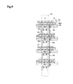
- FIG. 8 is a side view of the conveyance path.
- FIG. 9 is a perspective view showing coupling members of the conveyor device.
- FIG. 10 is a diagram showing a slide block of the conveyor device in which, (A) is a front view thereof and (B) is a side view thereof.
- FIG. 11 is a block line diagram showing a control system for the conveyor device.
- FIG. 12 is a perspective view of an entire conveyor device according to a second embodiment of the present invention.
- FIG. 13 is a perspective view of an entire conveyor device according to a third embodiment of the present invention.
- FIG. 14 is a front view of an entire a conventional spiral endless conveyor device.
- FIG. 1 A conveyor device for conveying food according to a first embodiment of the present invention will be described with reference to FIG. 1 to FIG. 11 .
- a freezer 10 having a closed structure excluding an inlet opening 10 a and an outlet opening 10 b is disposed, and a conveyor device 12 A is disposed in the freezer 10 .
- An endless conveyor path 14 disposed in a spiral endless conveyor device 12 includes: an inlet path 14 A which enters into the freezer 10 through the inlet opening 10 a ; a spiral ascending path 14 B spirally ascending from the inlet path 14 A; a turning back path 14 C turning back from the upper most portion of the spiral ascending path 14 B; a spiral descending path 14 D disposed so that stages of the spiral ascending path 14 B and stages of the spiral descending path 14 D are arranged alternately, the spiral descending path spirally descending from the turning back path 14 C; an outlet path 14 E extending from the lower most stage of the spiral descending path 14 D to the outside of the freezer 10 through an outlet opening 10 b ; and a return path 14 F which is reversed at an end of the outlet path 14 E with a guide sprocket 16 , and then is reversed again with a guide roller 18 to continue to the inlet path 14 A.
- the spiral ascending path 14 B and the spiral descending path 14 D move in opposite directions.
- a drive motor 16 a is provided in the guide sprocket 16 .
- a tension adjustment mechanism 20 for the endless conveyor path 14 is disposed on an outer side of a side wall 10 c of the freezer 10 on which the outlet opening 10 b is formed.
- the tension adjustment mechanism 20 includes a pair of guide sprockets 22 and 22 and a tension roller 24 which face the return path 14 F.
- the tension roller 24 can be moved in a vertical direction by a tension weight 26 .
- the tension of the endless conveyor path 14 is adjusted by the movement of the tension roller 24 .
- a tension detection sensor 28 which detects the tension of the return path 14 F is disposed at an outlet side portion of the tension roller 24 .
- the tension detection sensor 28 may be a contactless sensor or may employ a system of detecting counterforce acting on the tension roller 24 and calculating the tension of the return path 14 F from the detected value.
- the detected value from the tension detection sensor 28 is input to a control device 30 (refer to FIG. 11 ).
- FIG. 3 shows the inlet path 14 A protruding outside from the freezer 10 through the inlet opening 10 a .
- An operator places food on the conveyor belt at the inlet path 14 A.
- a conveyance mechanism 32 which is disposed adjacent to a spiral portion of the endless conveyor path 14 and moves the conveyor belt in a conveyance direction, and a housing 34 , which is vertically long and incorporates the conveyance mechanism 32 , stand in the freezer 10 .
- a configuration of the conveyance mechanism 32 will be described with reference to FIG. 4 .
- an upper portion of the housing 34 is disposed through a ceiling wall 10 d of the freezer 10 to protrude outside from the freezer 10 .
- a drive motor 36 and a decelerator 38 are disposed on a top surface of the housing 34 .
- Two rotational axes 40 and 42 are disposed in parallel in the vertical direction in the housing 34 .
- the rotational axes 40 and 42 are supported in the vertical direction by thrust bearings 44 and 46 supported on the ceiling wall 10 d in a normal temperature area outside the freezer 10 .
- the rotational axes 40 and 42 have a position in the horizontal direction fixed by a plurality of intermediate bearings 47 arranged in the vertical direction and fixed to the housing 34 .
- a plurality of sprockets 48 and 50 are respectively attached to the rotational axes 40 and 42 at positions corresponding to heights of the inlet path 14 A, the spiral ascending path 14 B, the spiral descending path 14 D, the outlet path 14 E, and the return path 14 F.
- the sprockets 48 and 50 are each formed of the above-described wear resistant resin member, mesh with rollers 74 of later-described coupling members 62 forming the conveyance path, and move the endless conveyor path 14 in the conveyance direction.
- Spur gears 51 and 52 are fixed to upper portions of the rotational axes 40 and 42 .
- Teeth counting sensors 54 and 56 which measure the number of teeth of the spur gears 51 and 52 passing through, are disposed at positions, in the housing 34 , facing the spur gears 51 and 52 .
- the rotational axes 40 and 42 are rotated in opposite directions by the drive motor 36 with the spur gears 51 and 52 meshing each other.
- the sprockets 48 mesh with the rollers 74 in the inlet path 14 A and the spiral ascending path 14 B.
- the sprockets 50 mesh with the rollers 74 in the spiral descending path 14 D and the return path 14 F.
- the inlet path 14 A and the return path 14 F as well as the spiral ascending path 14 B and the spiral descending path 14 D move in opposite directions.
- Tension adjustment devices 58 are disposed at outlet ends of the turning back path 14 C and the outlet path 14 E.
- the tension adjustment devices 58 each rotate the sprocket 58 b at a speed slightly faster than the movement speed of the endless conveyor path 14 .
- the slackening of the endless conveyor path 14 at the installed portions can be fixed.
- FIG. 5 to FIG. 8 each show a part of the spiral conveyance path including the spiral ascending path 14 B and the spiral descending path 14 D and show four spiral conveyor belts 15 a , 15 b , 15 c and 15 d disposed in the vertical direction.
- the spiral conveyor belts 15 a and 15 c form a part of the spiral ascending path 14 B
- the spiral conveyor belts 15 b and 15 d form a part of the spiral descending path 14 D.
- the spiral conveyor belts 15 a to 15 d include a large number of round bars 60 disposed in a horizontal direction.
- the coupling members 62 are attached to both ends of each round bar 60 .
- the round bars 60 are coupled to each other through the coupling members 62 to be arranged at a predetermined interval.
- the coupling members 62 are restricted in series in the conveyance direction via the round bars 60 .
- a slide block 78 is fixed to a portion of the round bar 60 on the inner side of the coupling members 62 .
- the spiral conveyor belts 15 a to 15 d are each supported by a spiral guide rail 86 disposed below the slide block 78 via the slide block 78 , and slide on the guide rail 86 .
- FIG. 9 is an enlarged view of the coupling members 62 .
- the coupling members 62 is formed by bending a plate material, made of stainless steel, into a U shape.
- a pair of slotted holes 66 a and 66 b are formed at positions facing each other between both end portions 65 and a top portion 64 .
- a pair of round holes 68 a and 68 b facing both end portions 65 are formed.
- An end portion of the round bar 60 is tightly fitted in the round holes 68 a and 68 b.
- An upper bracket 70 a and a lower bracket 70 b are integrally formed with one of both end portions 65 positioned on the outer side of the round bar 60 .
- the upper and lower brackets 70 a and 70 b are positioned on upper and lower sides of the conveyor belt formed of the round bars 60 , in the height direction of the conveyor belt, and are bent towards the outer side of the conveyor belt formed of the round bars 60 .
- a shaft 72 is attached to the upper and lower brackets 70 a and 70 b .
- the rollers 74 made of the wear resistant resin are rotatably attached to the shaft 72 .
- the shaft 72 is disposed in a direction orthogonal to the conveyance surface of spiral conveyor paths 14 a to 14 d.
- the round bar 60 adjacent to another round bar 60 tightly fitted in the round holes 68 a and 68 b , is inserted in the slotted holes 66 a and 66 b .
- Long sides 67 a and 67 b of the slotted holes 66 a and 66 b are disposed in the conveyance direction of the conveyor belt, and thus the round bars 60 are loosely fitted in the slotted holes 66 a and 66 b to be movable in the conveyance direction.
- an interval between the two adjacent round bars, restricted with a single coupling member 62 , in the conveyance direction can be changed.
- the slide block 78 is made of the above-described wear resistant resin, and includes: a slide portion 80 including slide surfaces 80 a and 80 b which are disposed on upper and lower sides of a semicircular recessed groove 84 , in which the corresponding round bar 60 is tightly fitted, and slide on the upper edge surface of the guide rail 86 ; and a guide portion 82 which is disposed on both sides of a fitted portion for the round bar 60 and protrudes in the vertical directions from the slide surfaces 80 a and 80 b .
- Guide surfaces 82 a and 82 b guided by side surfaces of the later-described guide rail 86 , are formed on inner side surfaces of the guide portion 82 .
- a protrusion 83 which has an arc shaped cross section and reduces friction on the guide rail 86 is formed on each of the guide surfaces 82 a and 82 b.
- the slide portion 80 has rectangular parallelepiped shape.
- the guide portion 82 has a rectangular plate shape protruding upward and downward from the slide portion 80 .
- the recessed groove 84 having a semicircular cross section is formed at the center of one side surface of the slide block 78 .
- the slide block 78 is fixed to the round bar 60 with the round bar 60 tightly fitted in the recessed groove 84 .
- the slide portion 80 and the guide portion 82 of the slide block 78 are each vertically symmetrical with respect to the recessed groove 84 .
- the interior areas of the slide portion 80 and the guide portion 82 have small thicknesses to achieve a light weight.
- the guide rail 86 is disposed over substantially the entire area of the endless conveyor path 14 , except for a certain portion (for example, an area where the tension adjustment mechanism 20 including the guide sprockets 22 and 22 and the tension roller 24 is disposed).
- the slide surfaces 80 a and 80 b of the slide portion 80 form flat surfaces in the horizontal direction.
- the slide surface 80 b is in slidable contact with the guide rail 86 having the flat upper edge surface, and slides on the guide rail 86 .
- the endless conveyor path 14 is vertically reversed, and thus the slide surface 80 a is in slidable contact with the upper edge surface of the guide rail 86 .
- the guide rail 86 has a spiral shape in the spiral ascending path 14 B and the spiral descending path 14 D.
- the guide surfaces 82 a and 82 b of the guide portion 82 are in slidable contact with the side surfaces of the guide rail 86 , and are guided by the guide rail 86 .
- the guide portion 82 guides the guide rail 86 , and prevent the slide surfaces 80 a and 80 b from falling off from the guide rail 86 .
- the guide rail 86 is made of metal such as stainless steel and is disposed below the slide block 78 between the conveyance paths.
- the spiral conveyor belt 15 a to 15 d are supported by the guide rail 86 in such a manner as to be movable in the conveyance direction.
- the guide rail 86 is fixed to supporting structures 88 disposed on both sides of the spiral conveyor belt 15 a to 15 d .
- Each of the supporting structures 88 is made of metal such as stainless steel, and includes: a support plate 88 a bolted to the guide rail 86 ; four arms 88 b which is integrally formed with the support plate 88 a and extends in a direction orthogonal to the support plate 88 a ; and a base portion 88 c in which the arms 88 b are integrally formed and disposed at an equal interval in the vertical direction.
- Columns 90 stand on both sides of the spiral conveyor belt 15 a to 15 d while being apart from each other by an appropriate interval.
- the base portion 88 c of the supporting structure 88 is bolted to the corresponding column 90 .
- An anti-drop plate 92 is bolted to a lower portion of the support plate 88 a .
- the anti-drop plate 92 is partially disposed in the conveyance direction instead of being disposed entirely, whereby flow of cold air between an upper space of the conveyor belt and an exterior space thereof is ensured.
- the anti-drop plate 92 is disposed on the inner side of the guide portion 82 , and prevents the food on the conveyance path from falling off the conveyance surface.
- the guide rail 86 and the support plate 88 a , the base portion 88 c and the columns 90 , and the support plate 88 a and the anti-drop plate 92 are bolted to each other through the slotted holes.
- the relative positions therebetween can be slightly adjusted in the horizontal direction or the vertical direction.
- the upper edge of the guide rail 86 in slidable contact with the slide portion 80 of the slide block 78 is covered with an U-shaped cover 94 made of the above-described wear resistant resin.
- FIG. 11 illustrates a control system for the spiral endless conveyor device 12 . Detection values from the tension detection sensor 28 , the teeth counting sensors 54 and 56 , and the counting sensor 96 are input to the control device 30 .
- the control device 30 controls operations of the drive motor 16 a , the drive motor 36 , the tension adjustment devices 58 , and the like based on these detection values.
- an extremely low temperature atmosphere at ⁇ 35° C. or the like for example is maintained in the freezer 10 .
- the food is placed on the conveyor belt in the inlet path 14 A and is frozen while being conveyed in the extremely low temperature atmosphere.
- the round bars 60 are either tightly fitted in the round holes 68 a and 68 b of one of the adjacent coupling members 62 or loosely fitted in the slotted holes 66 a and 66 b of the other one of the adjacent coupling members 62 .
- the round bars are arranged in parallel to form the conveyance path, while having the interval therebetween restricted with the coupling members 62 .
- the coupling members are coupled to each other in series in the conveyance direction by the round bars 60 .
- the round bar 60 inserted in the slotted holes 66 a and 66 b can move in the conveyance direction, whereby the interval between the round bars 60 can be adjusted.
- the detection value from the tension detection sensor 28 is input to the control device 30 .
- the control device 30 controls operations of the driving device 16 a and the tension adjustment devices 58 in such a manner that the tension of the conveyor belt forming the endless conveyor path 14 is prevented from being an abnormal value.
- the detection values from the teeth counting sensors 54 and 56 and the counting sensor 96 are input to the control device 30 .
- the control device 30 monitors a moving state of the endless conveyor path 14 .
- the shaft 72 of each roller 74 is disposed in the direction orthogonal to the conveyance surface of the spiral conveyor belts 15 a to 15 d , and thus can rotate in the rotation direction of the sprockets 48 and 50 , whereby slipping between the rollers 74 and the sprockets 48 and 50 can be reduced.
- the sprockets 48 and 50 and the rollers 74 are made of the wear resistant resin, and thus the members can be prevented from wearing. All things considered, the metal powder and the like are not produced as in the conventional case, whereby a favorable hygienic environment for the conveyed food can be maintained.
- the slide block 78 is made of the wear resistant resin, and the cover 94 made of the wear resistant resin is provided at the upper edge of the guide rail 86 .
- the powder dust can be prevented from being produced on the slide surface between the slide block 78 and the guide rail 86 .
- the slide block 78 includes the slide portion 80 and the guide portion 82 only.
- the slide portion 80 slides on the guide rail 86 .
- the slide block 78 does not surround the guide rail 86 , as in the case of the supported portion in Patent Document 3.
- the slackening of the conveyor belt can be easily fixed, and the contact pressure and the friction force between the slide block 78 and the guide rail 86 do not increase in the low temperature environment.
- the driving torque of the conveyance mechanism 32 can be prevented from increasing, and abrasion powder can be prevented from being produced on the slide surface on the guide rail 86 . All things considered, the quality of the food on the conveyor belt can be prevented from being adversely affected.
- the slide portion 80 of the slide block 78 includes the slide surfaces 80 a and 80 b in slidable contact with the guide rail 86 , on the upper and lower sides of the round bar 60 .
- the guide portion 82 includes the guide surfaces 82 a and 82 b guided by the guide rail 86 on the upper and lower sides.
- the endless conveyor path 14 can be supported by the guide rail 86 , and the endless conveyor path 14 can smoothly move.
- the protrusions 83 formed on the guide surfaces 82 a and 82 b can reduce the friction on the guide rail 86 , and thus the driving force of the drive motor 36 of the conveyance mechanism 32 can be reduced.
- the slide block 78 is provided for each round bar 60 , whereby the adjacent round bars are free of restriction.
- an intricate arc can be formed at the curved portion of the endless conveyor path 14 , and thus higher design freedom of the endless conveyor path 14 can be achieved.
- the slide block 78 can have a simple shape, and can be manufactured at a low cost.
- the tension detection sensor 28 constantly monitors the tension applied to the endless conveyor path 14 , and the control device 30 operates the drive motor 16 a of the guide sprocket 16 , whereby the tension can be adjusted. As described above, the slackening of the endless conveyor path 14 can be adjusted, and thus excessively high tension can be prevented from being applied to the endless conveyor path 14 .
- the teeth counting sensors 54 and 56 and the counting sensor 96 can constantly monitor the moving state of the endless conveyor path 14 , whereby abnormality of the spiral endless conveyor device 12 can be quickly detected.
- the conveyance mechanism 32 can apply conveyance force evenly on the spiral ascending path 14 B and the spiral descending path 14 D with the plurality of sprockets 48 and 50 fixed to the rotational axes 40 and 42 .
- the endless conveyor path 14 can uniformly move, whereby the slackening can be prevented from occurring.
- a single drive motor 36 is the only driving device required, whereby the simple and low cost configuration can be achieved.
- the anti-drop plate 92 can prevent the food on the conveyance surface from falling off the conveyance path.
- the guide rail 86 is fixed by the columns 90 standing on both sides of the conveyance path while being apart from each other by an appropriate distance, and the supporting structures 88 .
- the guide rail 86 can be fixed by a simple and low cost supporting structure, even when the conveyor belt has multiple stages in the vertical direction.
- the drive motor 36 , the decelerator 38 , the thrust bearings 44 and 46 , the spur gears 51 and 52 , and the teeth counting sensors 54 and 56 are disposed in the normal temperature area on the outer side of the ceiling wall 10 d , and thus can be maintained and repaired easily.
- the spiral ascending path 14 B and the spiral descending path 14 D are disposed so that stages of the spiral ascending path 14 B and staged of the spiral descending path 14 D are arranged alternately. Thus, space saving can be achieved in the freezer 10 .
- the inlet path 14 A and the outlet path 14 E are disposed at lower portions. Thus, the food can be easily put in and taken out, whereby labor saving and higher efficiency can be achieved.
- a conveyor device 12 B according to the present embodiment represents an example of a case where a load of the conveyance mechanism 32 is large.
- a drive motor 120 is disposed at the center of an upper edge portion of the spiral conveyance path including the spiral ascending path 14 B and the spiral descending path 14 D.
- the drive motor 120 has a larger capacity than the drive motor 36 according to the first embodiment.
- Two housings 34 are disposed at positions on opposite sides of the spiral conveyance path, and each housing 34 incorporates the conveyance mechanism 32 having the configuration that is the same as that in the first embodiment.
- Gearboxes 124 a and 124 b which drive the rotational axes 40 and 42 are disposed on top walls of the housings 34 .
- Driving shafts 122 a and 122 b extend from the drive motor 120 to be connected to the gearboxes 124 a and 124 b .
- Other configurations are the same as the counterparts in the first embodiment.
- the driving force from the drive motor 120 is transmitted to the rotational axes 40 and 42 in the conveyance mechanisms 32 through the gearboxes 124 a and 124 b .
- the two conveyance mechanisms 32 can be driven by a single drive motor 120 .
- the conveyance force is shared by the two conveyance mechanisms 32 on both sides of the spiral conveyance path, whereby the smooth movement of the spiral conveyance path can be achieved.
- a third embodiment of the present invention will be described with reference to FIG. 13 .
- a conveyor device 12 C according to the present embodiment, two spiral conveyance paths each including corresponding to one of the spiral ascending path 14 B and the spiral descending path 14 D are adjacently disposed in the freezer 10 .
- the housing 34 is provided to each of the two spiral conveyance paths.
- a conveyance mechanism 32 A is disposed in one of the housings 34
- a conveyance mechanism 32 B is disposed in the other one of the housings 34 .
- the conveyance mechanism 32 A includes only one rotational axis 40 to which the plurality of sprockets 48 according to the first embodiment shown in FIG. 4 are attached.
- the conveyance mechanism 32 B includes only one rotational axis 42 to which the plurality of sprockets 50 according to the first embodiment shown in FIG. 4 are attached.
- Teeth counting sensors having the configurations that are the same as those of the teeth counting sensors 54 , 56 according to the first embodiment shown in FIG. 4 are provided to the conveyance mechanisms 32 A and 32 B, and detect rotation amounts of the rotational axes 40 and 42 . Furthermore, a control device similar to the control device 30 shown in FIG. 11 is provided. The control device has a function of synchronizing the rotation speeds of the rotational axes 40 and 42 to synchronize the movement speeds of the conveyor belt forming the spiral ascending path 14 B and the conveyor belt forming the spiral descending path 14 D by receiving detection values from the teeth counting sensors provided to the conveyance mechanisms 32 A and 32 B.
- the other configurations are the same as the counterparts in the first embodiment.
- the spiral ascending path 14 B and the spiral descending path 14 D are separated from each other, and thus the spiral conveyance path having a simpler and lower cost configuration, compared with the second embodiment, can be achieved.
- the conveyance mechanisms 32 A and 32 B are different from the conveyance mechanism 32 according to the first embodiment in that only one rotational axis is provided and can each be configured for a spiral conveyance path moving in a single direction. Thus, a simple and low cost configuration can be achieved.
- the movement speeds of the conveyor belt forming the spiral ascending path 14 B and the conveyor belt forming the spiral descending path 14 D are synchronized. Thus, the conveyor belt forming the endless conveyor path 14 can be prevented from slackening and can move smoothly.
- a simple and low cost conveyor device for conveying food can be implemented in which metal powder can be prevented from being generated and contact pressure and friction between the guide rail and the slide portion can be prevented from increasing in a low temperature environment.
Landscapes
- Engineering & Computer Science (AREA)
- Mechanical Engineering (AREA)
- Health & Medical Sciences (AREA)
- Nutrition Science (AREA)
- Life Sciences & Earth Sciences (AREA)
- Chemical & Material Sciences (AREA)
- Food Science & Technology (AREA)
- Polymers & Plastics (AREA)
- Chain Conveyers (AREA)
- Structure Of Belt Conveyors (AREA)
- Framework For Endless Conveyors (AREA)
Applications Claiming Priority (5)
| Application Number | Priority Date | Filing Date | Title |
|---|---|---|---|
| JP2012-286311 | 2012-12-27 | ||
| JP2012286313 | 2012-12-27 | ||
| JP2012286311 | 2012-12-27 | ||
| JP2012-286313 | 2012-12-27 | ||
| PCT/JP2013/084128 WO2014103886A1 (ja) | 2012-12-27 | 2013-12-19 | 食品搬送用コンベア装置 |
Publications (2)
| Publication Number | Publication Date |
|---|---|
| US20160194154A1 US20160194154A1 (en) | 2016-07-07 |
| US9440793B2 true US9440793B2 (en) | 2016-09-13 |
Family
ID=51020973
Family Applications (1)
| Application Number | Title | Priority Date | Filing Date |
|---|---|---|---|
| US14/758,062 Active US9440793B2 (en) | 2012-12-27 | 2013-12-19 | Conveyor device for conveying food |
Country Status (7)
| Country | Link |
|---|---|
| US (1) | US9440793B2 (ja) |
| JP (1) | JP6026560B2 (ja) |
| BR (1) | BR112015015293B1 (ja) |
| CA (1) | CA2896682C (ja) |
| CL (1) | CL2015001653A1 (ja) |
| MX (1) | MX358327B (ja) |
| WO (1) | WO2014103886A1 (ja) |
Cited By (5)
| Publication number | Priority date | Publication date | Assignee | Title |
|---|---|---|---|---|
| US9669998B2 (en) * | 2015-08-12 | 2017-06-06 | Ivan Muchalov | Conveyor drive system |
| US10577183B2 (en) * | 2016-09-14 | 2020-03-03 | Cambridge International, Inc. | Edge drive mesh overlay conveyor belt |
| IT201900006102A1 (it) * | 2019-04-18 | 2020-10-18 | Incobra S R L | Maglia di collegamento per elementi di supporto per nastri trasportatori, elementi di supporto per nastri trasportatori, metodo per la realizzazione della maglia di collegamento e dell’elemento di supporto |
| US11470769B2 (en) * | 2017-10-17 | 2022-10-18 | Grimme Landmaschinenfabrik Gmbh & Co. Kg | Screening belt unit for a harvesting machine, and associated flap unit |
| US12048266B2 (en) | 2018-04-13 | 2024-07-30 | Grimme Landmaschinenfabrik Gmbh & Co. Kg | Screening belt unit for a harvesting machine, and corresponding flap unit |
Families Citing this family (5)
| Publication number | Priority date | Publication date | Assignee | Title |
|---|---|---|---|---|
| CN105366267A (zh) * | 2015-11-30 | 2016-03-02 | 重庆市贵荣塑胶制品有限公司 | 一种电脑键盘生产线上的链条式输送机构 |
| KR101798788B1 (ko) | 2016-10-20 | 2017-11-16 | 장동현 | 음식물 이송 건조장치 |
| CN110089691B (zh) * | 2018-01-31 | 2023-05-23 | 俞建翔 | 螺旋输送式多层卤蛋烘干装置及其工作方法 |
| WO2021262640A1 (en) * | 2020-06-23 | 2021-12-30 | John Bean Technologies Corporation | Detection of conveyor belt condition |
| CN117063133A (zh) | 2021-03-24 | 2023-11-14 | 发那科株式会社 | 控制装置 |
Citations (17)
| Publication number | Priority date | Publication date | Assignee | Title |
|---|---|---|---|---|
| US3809207A (en) | 1972-12-11 | 1974-05-07 | Velten & Pulver | Converging and diverging conveyor |
| US3938651A (en) * | 1973-03-07 | 1976-02-17 | Frigoscandia Contracting Ab | Self-supporting spiral conveyor |
| JPH03216409A (ja) | 1990-01-18 | 1991-09-24 | Denkoo:Kk | 連続処理装置 |
| US5228557A (en) * | 1991-11-27 | 1993-07-20 | Tecno Pool S.P.A. | Chain conveyor with improved drive device |
| JP3005224U (ja) | 1994-06-14 | 1994-12-13 | 日精株式会社 | ローラピンギヤ装置 |
| US5501319A (en) * | 1994-06-21 | 1996-03-26 | Ashworth Bros., Inc. | Conveyor belt with asymmetric edge links |
| JPH10157820A (ja) | 1996-11-29 | 1998-06-16 | Misuzu Koki Kk | 無端スパイラルコンベヤ装置 |
| US6202834B1 (en) | 1998-03-03 | 2001-03-20 | Span Tech Llc | Modular link conveyor with I-beam guide rail |
| JP2002050243A (ja) | 2000-08-07 | 2002-02-15 | Yazaki Corp | 平型ケーブルの製造方法及び押出成形金型の芯金 |
| JP3123226U (ja) | 2005-04-27 | 2006-07-06 | テクノ プール ソシエタ ペル アチオーニ | コンベヤーベルト用封じ込め側壁システム |
| JP2007169059A (ja) | 2005-12-21 | 2007-07-05 | Hsin-Hung Lee | 下入下出のスパイラルコンベア |
| US20080017483A1 (en) * | 2006-07-18 | 2008-01-24 | Tecno Pool S.P.A. | Belt of a chain conveyor with innovative drive links |
| US7494005B2 (en) * | 2005-09-30 | 2009-02-24 | Cambridge International, Inc. | Variable spaced conveyor belt |
| US20100282577A1 (en) * | 2009-05-08 | 2010-11-11 | Alit S.R.L. | Link of a side chain for conveyor belts |
| US20110284347A1 (en) | 2009-01-12 | 2011-11-24 | Laitram, L.L.C. | Metal-fused plastic conveyor belt components and methods of making |
| US8302765B2 (en) * | 2009-02-13 | 2012-11-06 | Tecnopool S.P.A. | Bar conveyor belt, particularly for the food industry |
| US9061829B2 (en) * | 2011-10-26 | 2015-06-23 | Cambridge International, Inc. | Conveyor belt with improved edge configuration |
Family Cites Families (5)
| Publication number | Priority date | Publication date | Assignee | Title |
|---|---|---|---|---|
| US4481782A (en) * | 1983-01-25 | 1984-11-13 | The Boc Group, Inc. | Methods and apparatus for refrigerating products |
| JP3005224B2 (ja) * | 1988-10-14 | 2000-01-31 | 日本電気株式会社 | 電源システム |
| JPH0537729U (ja) * | 1991-10-23 | 1993-05-21 | 三鈴工機株式会社 | バーコンベヤ騒音防止装置 |
| JP3123226B2 (ja) * | 1992-05-28 | 2001-01-09 | ソニー株式会社 | オーミック電極及びその形成方法 |
| JPH0676217U (ja) * | 1993-04-09 | 1994-10-28 | 株式会社フジテツモーテクニカルサービス | ネットコンベヤ用ベルト |
-
2013
- 2013-12-19 CA CA2896682A patent/CA2896682C/en active Active
- 2013-12-19 WO PCT/JP2013/084128 patent/WO2014103886A1/ja active Application Filing
- 2013-12-19 BR BR112015015293-7A patent/BR112015015293B1/pt active IP Right Grant
- 2013-12-19 JP JP2014554386A patent/JP6026560B2/ja active Active
- 2013-12-19 US US14/758,062 patent/US9440793B2/en active Active
- 2013-12-19 MX MX2015008344A patent/MX358327B/es active IP Right Grant
-
2015
- 2015-06-12 CL CL2015001653A patent/CL2015001653A1/es unknown
Patent Citations (20)
| Publication number | Priority date | Publication date | Assignee | Title |
|---|---|---|---|---|
| US3809207A (en) | 1972-12-11 | 1974-05-07 | Velten & Pulver | Converging and diverging conveyor |
| US3938651A (en) * | 1973-03-07 | 1976-02-17 | Frigoscandia Contracting Ab | Self-supporting spiral conveyor |
| JPH03216409A (ja) | 1990-01-18 | 1991-09-24 | Denkoo:Kk | 連続処理装置 |
| US5228557A (en) * | 1991-11-27 | 1993-07-20 | Tecno Pool S.P.A. | Chain conveyor with improved drive device |
| JP3005224U (ja) | 1994-06-14 | 1994-12-13 | 日精株式会社 | ローラピンギヤ装置 |
| US5501319A (en) * | 1994-06-21 | 1996-03-26 | Ashworth Bros., Inc. | Conveyor belt with asymmetric edge links |
| JPH10157820A (ja) | 1996-11-29 | 1998-06-16 | Misuzu Koki Kk | 無端スパイラルコンベヤ装置 |
| US6202834B1 (en) | 1998-03-03 | 2001-03-20 | Span Tech Llc | Modular link conveyor with I-beam guide rail |
| JP2002050243A (ja) | 2000-08-07 | 2002-02-15 | Yazaki Corp | 平型ケーブルの製造方法及び押出成形金型の芯金 |
| JP3123226U (ja) | 2005-04-27 | 2006-07-06 | テクノ プール ソシエタ ペル アチオーニ | コンベヤーベルト用封じ込め側壁システム |
| US7494005B2 (en) * | 2005-09-30 | 2009-02-24 | Cambridge International, Inc. | Variable spaced conveyor belt |
| JP2007169059A (ja) | 2005-12-21 | 2007-07-05 | Hsin-Hung Lee | 下入下出のスパイラルコンベア |
| JP2008056489A (ja) | 2006-07-18 | 2008-03-13 | Tecno Pool Spa | 革新的駆動連結具を備えたチェーンコンベアベルト |
| US20080017483A1 (en) * | 2006-07-18 | 2008-01-24 | Tecno Pool S.P.A. | Belt of a chain conveyor with innovative drive links |
| US7762388B2 (en) * | 2006-07-18 | 2010-07-27 | Tecno Pool S.P.A. | Belt of a chain conveyor with innovative drive links |
| US20110284347A1 (en) | 2009-01-12 | 2011-11-24 | Laitram, L.L.C. | Metal-fused plastic conveyor belt components and methods of making |
| JP2012515124A (ja) | 2009-01-12 | 2012-07-05 | レイトラム,エル.エル.シー. | 金属を溶着したプラスチックコンベヤベルト部品及び作製方法 |
| US8302765B2 (en) * | 2009-02-13 | 2012-11-06 | Tecnopool S.P.A. | Bar conveyor belt, particularly for the food industry |
| US20100282577A1 (en) * | 2009-05-08 | 2010-11-11 | Alit S.R.L. | Link of a side chain for conveyor belts |
| US9061829B2 (en) * | 2011-10-26 | 2015-06-23 | Cambridge International, Inc. | Conveyor belt with improved edge configuration |
Non-Patent Citations (4)
| Title |
|---|
| International Preliminary Report issued in PCT/JP2013/084128 Form PCT/IB/338 and PCT/IB/373, dated Jul. 9, 2015. |
| International Search Report issued in PCT/JP2013/084128 dated Apr. 8, 2014. English translation provided. |
| Japanese Office Action issued in counterpart application No. JP2014554386, dated Dec. 18, 2015. English translation provided. |
| Written Opinion issued in PCT/JP2013/084128 Form PCT/ISA/237, dated Apr. 8, 2014. |
Cited By (8)
| Publication number | Priority date | Publication date | Assignee | Title |
|---|---|---|---|---|
| US9669998B2 (en) * | 2015-08-12 | 2017-06-06 | Ivan Muchalov | Conveyor drive system |
| US10577183B2 (en) * | 2016-09-14 | 2020-03-03 | Cambridge International, Inc. | Edge drive mesh overlay conveyor belt |
| US11470769B2 (en) * | 2017-10-17 | 2022-10-18 | Grimme Landmaschinenfabrik Gmbh & Co. Kg | Screening belt unit for a harvesting machine, and associated flap unit |
| US12048266B2 (en) | 2018-04-13 | 2024-07-30 | Grimme Landmaschinenfabrik Gmbh & Co. Kg | Screening belt unit for a harvesting machine, and corresponding flap unit |
| IT201900006102A1 (it) * | 2019-04-18 | 2020-10-18 | Incobra S R L | Maglia di collegamento per elementi di supporto per nastri trasportatori, elementi di supporto per nastri trasportatori, metodo per la realizzazione della maglia di collegamento e dell’elemento di supporto |
| WO2020212929A1 (en) * | 2019-04-18 | 2020-10-22 | Incobra S.R.L. | Link for support members of conveyor belts, support member of conveyor belts and method for manufacturing a link |
| US20220297946A1 (en) * | 2019-04-18 | 2022-09-22 | Incobra S.R.L. | Link for support members of conveyor belts, support member of conveyor belts and method for manufacturing a link |
| US11760579B2 (en) * | 2019-04-18 | 2023-09-19 | Incobra S.R.L. | Link for support members of conveyor belts, support member of conveyor belts and method for manufacturing a link |
Also Published As
| Publication number | Publication date |
|---|---|
| CA2896682C (en) | 2017-01-24 |
| BR112015015293A2 (pt) | 2017-07-11 |
| CA2896682A1 (en) | 2014-07-03 |
| JP6026560B2 (ja) | 2016-11-16 |
| MX2015008344A (es) | 2015-11-09 |
| JPWO2014103886A1 (ja) | 2017-01-12 |
| BR112015015293B1 (pt) | 2021-01-19 |
| MX358327B (es) | 2018-08-15 |
| WO2014103886A1 (ja) | 2014-07-03 |
| US20160194154A1 (en) | 2016-07-07 |
| CL2015001653A1 (es) | 2016-01-20 |
Similar Documents
| Publication | Publication Date | Title |
|---|---|---|
| US9540176B2 (en) | Conveyor device for conveying food | |
| US9440793B2 (en) | Conveyor device for conveying food | |
| US9139371B2 (en) | Spiral conveyor | |
| RU2595222C2 (ru) | Устройство для накопления изделий | |
| MX2011001616A (es) | Ensamble transportador. | |
| US11027924B2 (en) | Device for moving endless conveyor chains | |
| EP2895408B1 (en) | Apparatus for assisting the movement of a chain | |
| EP3085645B1 (en) | Apparatus for transporting objects | |
| CA2858609A1 (en) | Zero tension system conveyor | |
| JP5068143B2 (ja) | パン生地搬送装置及びプルーファー | |
| WO2015193907A1 (en) | A flexible element for a conveyor system | |
| EP4036038B1 (en) | Motorized transfer apparatus for conveyors of bulk objects | |
| EP2834534B1 (en) | Cable chain system | |
| CN115744295A (zh) | 一种可动态调节宽度的玻璃基板输送机及其运行方法 | |
| EP3050827A1 (en) | Compact gear and drive unit | |
| ITPD20010086U1 (it) | Gruppo di trasmissione del moto per trasportatori flessibili a catena | |
| WO2006104380A1 (en) | Belt conveyor with curved sections |
Legal Events
| Date | Code | Title | Description |
|---|---|---|---|
| AS | Assignment |
Owner name: MAYEKAWA MFG. CO., LTD., JAPAN Free format text: ASSIGNMENT OF ASSIGNORS INTEREST;ASSIGNORS:MATSUZAKI, TOMOHIKO;ISHIKURA, KOU;SEKITA, TAKAYUKI;AND OTHERS;REEL/FRAME:035916/0682 Effective date: 20150625 |
|
| STCF | Information on status: patent grant |
Free format text: PATENTED CASE |
|
| MAFP | Maintenance fee payment |
Free format text: PAYMENT OF MAINTENANCE FEE, 4TH YEAR, LARGE ENTITY (ORIGINAL EVENT CODE: M1551); ENTITY STATUS OF PATENT OWNER: LARGE ENTITY Year of fee payment: 4 |
|
| MAFP | Maintenance fee payment |
Free format text: PAYMENT OF MAINTENANCE FEE, 8TH YEAR, LARGE ENTITY (ORIGINAL EVENT CODE: M1552); ENTITY STATUS OF PATENT OWNER: LARGE ENTITY Year of fee payment: 8 |