US9157667B2 - Heat pump-type heating device - Google Patents
Heat pump-type heating device Download PDFInfo
- Publication number
- US9157667B2 US9157667B2 US13/883,479 US201113883479A US9157667B2 US 9157667 B2 US9157667 B2 US 9157667B2 US 201113883479 A US201113883479 A US 201113883479A US 9157667 B2 US9157667 B2 US 9157667B2
- Authority
- US
- United States
- Prior art keywords
- heat
- heat pump
- unit
- refrigerant
- binary
- Prior art date
- Legal status (The legal status is an assumption and is not a legal conclusion. Google has not performed a legal analysis and makes no representation as to the accuracy of the status listed.)
- Expired - Fee Related, expires
Links
- 238000010438 heat treatment Methods 0.000 title claims abstract description 149
- 239000003507 refrigerant Substances 0.000 claims abstract description 133
- CURLTUGMZLYLDI-UHFFFAOYSA-N Carbon dioxide Chemical compound O=C=O CURLTUGMZLYLDI-UHFFFAOYSA-N 0.000 claims abstract description 26
- 229910002092 carbon dioxide Inorganic materials 0.000 claims abstract description 20
- 239000001569 carbon dioxide Substances 0.000 claims abstract description 20
- XLYOFNOQVPJJNP-UHFFFAOYSA-N water Substances O XLYOFNOQVPJJNP-UHFFFAOYSA-N 0.000 claims description 59
- 230000008020 evaporation Effects 0.000 claims description 39
- 238000001704 evaporation Methods 0.000 claims description 39
- 238000005057 refrigeration Methods 0.000 description 36
- 230000006835 compression Effects 0.000 description 21
- 238000007906 compression Methods 0.000 description 21
- 238000010521 absorption reaction Methods 0.000 description 10
- 230000004048 modification Effects 0.000 description 7
- 238000012986 modification Methods 0.000 description 7
- 239000007787 solid Substances 0.000 description 5
- 230000006866 deterioration Effects 0.000 description 3
- 238000004088 simulation Methods 0.000 description 3
- 230000003247 decreasing effect Effects 0.000 description 2
- 238000011144 upstream manufacturing Methods 0.000 description 2
- 230000004913 activation Effects 0.000 description 1
- 230000005494 condensation Effects 0.000 description 1
- 238000009833 condensation Methods 0.000 description 1
- 230000000694 effects Effects 0.000 description 1
- 230000006872 improvement Effects 0.000 description 1
- 238000000034 method Methods 0.000 description 1
- 230000008569 process Effects 0.000 description 1
Images


Classifications
-
- F—MECHANICAL ENGINEERING; LIGHTING; HEATING; WEAPONS; BLASTING
- F25—REFRIGERATION OR COOLING; COMBINED HEATING AND REFRIGERATION SYSTEMS; HEAT PUMP SYSTEMS; MANUFACTURE OR STORAGE OF ICE; LIQUEFACTION SOLIDIFICATION OF GASES
- F25B—REFRIGERATION MACHINES, PLANTS OR SYSTEMS; COMBINED HEATING AND REFRIGERATION SYSTEMS; HEAT PUMP SYSTEMS
- F25B7/00—Compression machines, plants or systems, with cascade operation, i.e. with two or more circuits, the heat from the condenser of one circuit being absorbed by the evaporator of the next circuit
-
- F—MECHANICAL ENGINEERING; LIGHTING; HEATING; WEAPONS; BLASTING
- F24—HEATING; RANGES; VENTILATING
- F24D—DOMESTIC- OR SPACE-HEATING SYSTEMS, e.g. CENTRAL HEATING SYSTEMS; DOMESTIC HOT-WATER SUPPLY SYSTEMS; ELEMENTS OR COMPONENTS THEREFOR
- F24D19/00—Details
- F24D19/10—Arrangement or mounting of control or safety devices
- F24D19/1006—Arrangement or mounting of control or safety devices for water heating systems
- F24D19/1009—Arrangement or mounting of control or safety devices for water heating systems for central heating
- F24D19/1039—Arrangement or mounting of control or safety devices for water heating systems for central heating the system uses a heat pump
-
- F—MECHANICAL ENGINEERING; LIGHTING; HEATING; WEAPONS; BLASTING
- F24—HEATING; RANGES; VENTILATING
- F24D—DOMESTIC- OR SPACE-HEATING SYSTEMS, e.g. CENTRAL HEATING SYSTEMS; DOMESTIC HOT-WATER SUPPLY SYSTEMS; ELEMENTS OR COMPONENTS THEREFOR
- F24D3/00—Hot-water central heating systems
- F24D3/18—Hot-water central heating systems using heat pumps
-
- F—MECHANICAL ENGINEERING; LIGHTING; HEATING; WEAPONS; BLASTING
- F25—REFRIGERATION OR COOLING; COMBINED HEATING AND REFRIGERATION SYSTEMS; HEAT PUMP SYSTEMS; MANUFACTURE OR STORAGE OF ICE; LIQUEFACTION SOLIDIFICATION OF GASES
- F25B—REFRIGERATION MACHINES, PLANTS OR SYSTEMS; COMBINED HEATING AND REFRIGERATION SYSTEMS; HEAT PUMP SYSTEMS
- F25B1/00—Compression machines, plants or systems with non-reversible cycle
-
- F—MECHANICAL ENGINEERING; LIGHTING; HEATING; WEAPONS; BLASTING
- F25—REFRIGERATION OR COOLING; COMBINED HEATING AND REFRIGERATION SYSTEMS; HEAT PUMP SYSTEMS; MANUFACTURE OR STORAGE OF ICE; LIQUEFACTION SOLIDIFICATION OF GASES
- F25B—REFRIGERATION MACHINES, PLANTS OR SYSTEMS; COMBINED HEATING AND REFRIGERATION SYSTEMS; HEAT PUMP SYSTEMS
- F25B30/00—Heat pumps
- F25B30/02—Heat pumps of the compression type
-
- F—MECHANICAL ENGINEERING; LIGHTING; HEATING; WEAPONS; BLASTING
- F25—REFRIGERATION OR COOLING; COMBINED HEATING AND REFRIGERATION SYSTEMS; HEAT PUMP SYSTEMS; MANUFACTURE OR STORAGE OF ICE; LIQUEFACTION SOLIDIFICATION OF GASES
- F25B—REFRIGERATION MACHINES, PLANTS OR SYSTEMS; COMBINED HEATING AND REFRIGERATION SYSTEMS; HEAT PUMP SYSTEMS
- F25B49/00—Arrangement or mounting of control or safety devices
- F25B49/02—Arrangement or mounting of control or safety devices for compression type machines, plants or systems
-
- F—MECHANICAL ENGINEERING; LIGHTING; HEATING; WEAPONS; BLASTING
- F25—REFRIGERATION OR COOLING; COMBINED HEATING AND REFRIGERATION SYSTEMS; HEAT PUMP SYSTEMS; MANUFACTURE OR STORAGE OF ICE; LIQUEFACTION SOLIDIFICATION OF GASES
- F25B—REFRIGERATION MACHINES, PLANTS OR SYSTEMS; COMBINED HEATING AND REFRIGERATION SYSTEMS; HEAT PUMP SYSTEMS
- F25B6/00—Compression machines, plants or systems, with several condenser circuits
- F25B6/04—Compression machines, plants or systems, with several condenser circuits arranged in series
-
- F—MECHANICAL ENGINEERING; LIGHTING; HEATING; WEAPONS; BLASTING
- F25—REFRIGERATION OR COOLING; COMBINED HEATING AND REFRIGERATION SYSTEMS; HEAT PUMP SYSTEMS; MANUFACTURE OR STORAGE OF ICE; LIQUEFACTION SOLIDIFICATION OF GASES
- F25B—REFRIGERATION MACHINES, PLANTS OR SYSTEMS; COMBINED HEATING AND REFRIGERATION SYSTEMS; HEAT PUMP SYSTEMS
- F25B9/00—Compression machines, plants or systems, in which the refrigerant is air or other gas of low boiling point
- F25B9/002—Compression machines, plants or systems, in which the refrigerant is air or other gas of low boiling point characterised by the refrigerant
- F25B9/008—Compression machines, plants or systems, in which the refrigerant is air or other gas of low boiling point characterised by the refrigerant the refrigerant being carbon dioxide
-
- F—MECHANICAL ENGINEERING; LIGHTING; HEATING; WEAPONS; BLASTING
- F24—HEATING; RANGES; VENTILATING
- F24D—DOMESTIC- OR SPACE-HEATING SYSTEMS, e.g. CENTRAL HEATING SYSTEMS; DOMESTIC HOT-WATER SUPPLY SYSTEMS; ELEMENTS OR COMPONENTS THEREFOR
- F24D2200/00—Heat sources or energy sources
- F24D2200/12—Heat pump
- F24D2200/123—Compression type heat pumps
-
- F—MECHANICAL ENGINEERING; LIGHTING; HEATING; WEAPONS; BLASTING
- F25—REFRIGERATION OR COOLING; COMBINED HEATING AND REFRIGERATION SYSTEMS; HEAT PUMP SYSTEMS; MANUFACTURE OR STORAGE OF ICE; LIQUEFACTION SOLIDIFICATION OF GASES
- F25B—REFRIGERATION MACHINES, PLANTS OR SYSTEMS; COMBINED HEATING AND REFRIGERATION SYSTEMS; HEAT PUMP SYSTEMS
- F25B2309/00—Gas cycle refrigeration machines
- F25B2309/06—Compression machines, plants or systems characterised by the refrigerant being carbon dioxide
- F25B2309/061—Compression machines, plants or systems characterised by the refrigerant being carbon dioxide with cycle highest pressure above the supercritical pressure
-
- F—MECHANICAL ENGINEERING; LIGHTING; HEATING; WEAPONS; BLASTING
- F25—REFRIGERATION OR COOLING; COMBINED HEATING AND REFRIGERATION SYSTEMS; HEAT PUMP SYSTEMS; MANUFACTURE OR STORAGE OF ICE; LIQUEFACTION SOLIDIFICATION OF GASES
- F25B—REFRIGERATION MACHINES, PLANTS OR SYSTEMS; COMBINED HEATING AND REFRIGERATION SYSTEMS; HEAT PUMP SYSTEMS
- F25B2339/00—Details of evaporators; Details of condensers
- F25B2339/04—Details of condensers
- F25B2339/047—Water-cooled condensers
-
- F—MECHANICAL ENGINEERING; LIGHTING; HEATING; WEAPONS; BLASTING
- F25—REFRIGERATION OR COOLING; COMBINED HEATING AND REFRIGERATION SYSTEMS; HEAT PUMP SYSTEMS; MANUFACTURE OR STORAGE OF ICE; LIQUEFACTION SOLIDIFICATION OF GASES
- F25B—REFRIGERATION MACHINES, PLANTS OR SYSTEMS; COMBINED HEATING AND REFRIGERATION SYSTEMS; HEAT PUMP SYSTEMS
- F25B2600/00—Control issues
- F25B2600/25—Control of valves
- F25B2600/2513—Expansion valves
-
- Y—GENERAL TAGGING OF NEW TECHNOLOGICAL DEVELOPMENTS; GENERAL TAGGING OF CROSS-SECTIONAL TECHNOLOGIES SPANNING OVER SEVERAL SECTIONS OF THE IPC; TECHNICAL SUBJECTS COVERED BY FORMER USPC CROSS-REFERENCE ART COLLECTIONS [XRACs] AND DIGESTS
- Y02—TECHNOLOGIES OR APPLICATIONS FOR MITIGATION OR ADAPTATION AGAINST CLIMATE CHANGE
- Y02B—CLIMATE CHANGE MITIGATION TECHNOLOGIES RELATED TO BUILDINGS, e.g. HOUSING, HOUSE APPLIANCES OR RELATED END-USER APPLICATIONS
- Y02B30/00—Energy efficient heating, ventilation or air conditioning [HVAC]
- Y02B30/12—Hot water central heating systems using heat pumps
Definitions
- the present invention relates to a heat pump-type heating device, and more specifically, to a technology of improving COP by using a heat pump having a binary compression refrigeration circuit to perform heating.
- Units having such a binary compression refrigeration circuit include, for example, the refrigeration unit described in Patent Document 1.
- a low temperature-side refrigeration circuit is formed of a compressor, a condensation section of a cascade heat exchanger, an expansion valve and an evaporator, which are connected in order using refrigerant pipes
- a high temperature-side refrigeration circuit is formed of a compressor, a condenser, an expansion valve and an evaporation section of the cascade heat exchanger, which are connected in order using refrigerant pipes.
- a unitary compression refrigeration circuit compresses and delivers refrigerant from the evaporator located on a low temperature-side section of the circuit to the condenser located on a high temperature-side section at one time at a high compression ratio, so that the compressor efficiency is not good.
- the binary compression refrigeration circuit is used, the compression ratio of the compressor of the high temperature-side refrigeration circuit and that of the compressor of the low temperature-side refrigeration circuit can be kept low, and the compressor efficiencies are improved.
- the hot-water supply system described in Patent Document 2 uses a binary compression refrigeration circuit, so that it is possible to perform high-temperature hot water supply through low temperature-side and high temperature-side refrigeration circuits, and even properly perform mid-temperature hot water supply through the low-temperature refrigeration circuit.
- the heat-pump hot-water supply system described in Patent Document 3 uses a binary compression refrigeration circuit, so that it is possible to perform preheating through a low temperature-side refrigeration circuit and also perform high-temperature hot water supply through the low temperature-side refrigeration circuit and a high temperature-side refrigeration circuit.
- Patent Document 1 Unexamined Japanese Patent Publication (Kokai) No. 2000-320914
- Patent Document 2 Unexamined Japanese Patent Publication (Kokai) No. 62-77554
- Patent Document 3 Japanese Patent No. 2554208
- a binary compression refrigeration circuit is formed of a low temperature-side refrigeration circuit and a high temperature-side refrigeration circuit with a cascade heat exchanger intervening therebetween, as shown in FIG. 10 of a conventional common Mollier chart (solid line) of the binary compression refrigeration circuit, in comparison with a unitary compression refrigeration circuit (broken line), when low temperature is desired (low temperature-side refrigeration circuit), enthalpy difference is increased, and low temperature can be satisfactory created.
- low temperature-side refrigeration circuit low temperature-side refrigeration circuit
- enthalpy difference is decreased.
- COP coefficient of performance
- the binary compression refrigeration circuit using CO 2 as refrigerant like the one mentioned above cannot efficiently use the heat in a range shown by the arrow, which is the heat (residual heat) that cannot be used directly for heating purpose due to its low temperature but has higher temperature than outside air temperature (heat absorption source) and is therefore usable as a heat absorption source of the refrigeration circuit.
- the invention has been made in light of the above issue. It is an object of the invention to provide a heat pump-type heating device that sufficiently improves COP by using a binary compression refrigeration circuit.
- the heat pump-type heating device of the invention has a heating unit that circulates heat media to a heating terminal; a unitary-side heat pump unit in which refrigerant circulates sequentially through a first compressor, a first heat exchanger, a cascade heat exchanger, a first expansion valve and an evaporator, and heat exchange with the heat media of the heating unit is carried out in the first heat exchanger; a binary-side heat pump unit in which refrigerant circulates sequentially through a second compressor, a second heat exchanger, a second expansion valve and a cascade heat exchanger, and heat exchange with heat media of a heating unit is carried out in the second heat exchanger; and a controller that controls the heating unit and the unitary-side and binary-side heat pump units.
- the refrigerants of the unitary-side and binary-side heat pump units include carbon dioxide as a main component.
- the controller activates both high pressure-side sections of the unitary-side and binary-side heat pump units within substantially identical pressure ranges of supercritical pressure (claim 1 ).
- the controller controls evaporation temperature of the refrigerant of the binary-side heat pump unit to be equal to or higher than evaporation temperature of the refrigerant of the unitary-side heat pump unit (claim 2 ).
- the controller preferably controls the evaporation temperature of the refrigerant of the binary-side heat pump unit to be equal to or lower than a critical point and equal to or higher than predetermined temperature (claim 3 ).
- the predetermined temperature is preferably 15 degrees centigrade (claim 4 ).
- the controller controls the evaporation temperature of the refrigerant of the binary-side heat pump unit to be equal to or higher than the evaporation temperature of the refrigerant of the unitary heat pump unit and lower than the predetermined temperature (claim 5 ).
- the binary-side heat pump unit preferably has a binary-side internal heat exchanging device that performs heating by carrying out heat exchange between the refrigerant that has passed through the cascade heat exchanger and the refrigerant existing between the second compressor and the second expansion valve (claim 6 ).
- the unitary-side heat pump unit preferably has a unitary-side internal heat exchanging device that performs heating by carrying out heat exchange between the refrigerant that has passed through the evaporator and the refrigerant existing between the first compressor and the first expansion valve (claim 7 ).
- a temperature detecting device that detects the temperature of the refrigerant that has passed through the first compressor, and the controller controls a flow rate of the refrigerant that passes through the evaporator and undergoes the heat exchange in the unitary-side internal heat exchanging device so that the temperature of the refrigerant, which is detected by the temperature detecting device, becomes equal to predetermined temperature (claim 8 ).
- thermo unit that circulates the heat media, and the refrigerant of the unitary-side heat pump unit undergoes heat exchange with the heat media circulating through the heating unit, whereas the refrigerant of the binary-side heat pump unit undergoes heat exchange with the heat media circulating through the thermal unit (claim 9 ).
- thermo unit that circulates the same heat media as the heat media of the heating unit, and the controller circulates the heat media that have undergone heat exchange with the refrigerant of the unitary-side heat pump unit, and circulates the heat media that have undergone heat exchange with the refrigerant of the binary-side heat pump unit, after dividing the heat media between the heating unit and the thermal unit (claim 10 ).
- the thermal unit is preferably a hot-water supply unit (claim 11 ).
- the heating unit, the unitary-side heat pump unit and the binary-side heat pump unit are provided;
- the unitary-side heat pump unit is configured so that the refrigerant circulates sequentially through the first compressor, the first heat exchanger, the cascade heat exchanger, the first expansion valve and the evaporator, and heat exchange with the heat media of the heating unit is carried out in the first heat exchanger;
- the binary-side heat pump unit is configured so that the refrigerant circulates sequentially through the second compressor, the second heat exchanger, the second expansion valve and the cascade heat exchanger, and heat exchange with the heat media of the heating unit is carried out in the second heat exchanger;
- the refrigerants of the unitary-side and binary-side heat pump units include carbon dioxide (CO 2 ) as a main component; and the high pressure-side sections of the unitary-side and binary-side heat pump units are activated within substantially identical pressure ranges of supercritical pressure.
- both the unitary side and the binary side can create high temperature, so that the heating performance can be improved.
- the binary-side heat pump unit uses residual heat as a heat absorption source, which cannot be used directly for heating purpose in the unitary-side heat pump unit, but has higher temperature than outside air temperature, so that a compression ratio is lower, as compared to when outside air is used as a heat absorption source, and COP is well improved (claim 1 ).
- COP Since the evaporation temperature of the refrigerant of the binary-side heat pump unit is controlled to be equal to or lower than a critical point and equal to or higher than predetermined temperature, COP is well improved (claim 3 ).
- the predetermined temperature is set to 15 degrees centigrade, and the evaporation temperature of the refrigerant of the binary-side heat pump unit is controlled to be equal to or lower than the critical point and equal to higher than 15 degrees centigrade, so that COP is well improved (claim 4 ).
- the evaporation temperature of the refrigerant of the binary-side heat pump unit is controlled to be equal to or higher than the evaporation temperature of the refrigerant of the unitary heat pump unit and lower than the predetermined temperature.
- the heating performance can be sufficiently secured while minimizing efficiency deterioration (claim 5 ).
- the binary-side heat pump unit includes the binary-side internal heat exchanging device that performs heating by carrying out heat exchange between the refrigerant that has passed through the cascade heat exchanger and the refrigerant existing between the second compressor and the second expansion valve. This increases enthalpy at an inlet and therefore outlet of the second compressor, so that the heating performance and thus COP is further improved (claim 6 ).
- the unitary-side heat pump unit includes the unitary-side internal heat exchanging device that performs heating by carrying out heat exchange between the refrigerant that has passed through the evaporator and the refrigerant existing between the first compressor and the first expansion valve. This increases enthalpy at an inlet and therefore outlet of the first compressor, so that the heating performance and thus COP is further improved (claim 7 ).
- the temperature detecting device that detects the temperature of the refrigerant that has passed through the first compressor, and the flow rate of the refrigerant that passes through the evaporator and undergoes the heat exchange in the unitary-side internal heat exchanging device is controlled so that the temperature of the refrigerant, which is detected by the temperature detecting device, becomes equal to predetermined temperature. This prevents the device from being damaged when the refrigerant that has passed through the first compressor is abnormally overheated (claim 8 ).
- the thermal unit that circulates the heat media, and the refrigerant of the unitary-side heat pump unit undergoes heat exchange with the heat media circulating through the heating unit, whereas the refrigerant of the binary-side heat pump unit undergoes heat exchange with the heat media circulating through the thermal unit.
- the device can be used in not only the heating unit but also the thermal unit.
- the heat media circulating through the heating unit and the heat media circulating through the thermal unit can be set to different temperatures according to an operating condition of the unitary-side and binary-side heat pump units and that of the heating and thermal units (claim 9 ).
- a thermal unit that circulates the same heat media as the heat media of the heating unit, and the controller circulates the heat media that have undergone heat exchange with the refrigerant of the unitary-side heat pump unit, and circulates the heat media, which have undergone heat exchange with the refrigerant of the binary-side heat pump unit, after dividing the heat media between the heating unit and the thermal unit.
- the device therefore can be used in not only the heating unit but also the thermal unit. Since the heat, which is obtained through heat exchange with the refrigerant of the binary-side heat pump unit, is divided between the heating unit and the thermal unit, especially the performance of the heating unit is enhanced (claim 10 ).
- the device can be used in not only the heating unit but also the hot-water supply unit.
- the hot-water supply unit low-temperature water is made into high-temperature water, so that enthalpy difference can be made large in the high pressure-side section of the binary-side heat pump unit, and the heat media (water) is efficiently heated (claim 11 ).
- FIG. 1 is a schematic configuration view showing a heat pump-type heating device according to a first embodiment of the present invention.
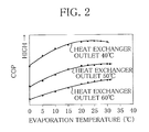
- FIG. 2 shows a relationship between evaporation temperature of a refrigerant in a binary-side heat pump unit and COP of the heat pump-type heating device.
- FIG. 3 is a Mollier chart related to the first embodiment.
- FIG. 4 shows a relationship between evaporation temperature of a refrigerant in a binary-side heat pump unit and heat quantity (high temperature output of the binary-side heat pump unit).
- FIG. 5 is a schematic configuration view showing a heat pump-type heating device according to a second embodiment of the present invention.
- FIG. 6 is a Mollier chart related to the second embodiment.
- FIG. 7 is a schematic configuration view showing a heat pump-type heating device according to a third embodiment of the present invention.
- FIG. 8 is a Mollier chart related to the third embodiment.
- FIG. 9 is a schematic configuration view showing a heat pump-type heating device according to the third embodiment of the present invention.
- FIG. 10 is a conventional common Mollier chart of a binary compression refrigeration circuit.
- FIG. 11 is a conventional common Mollier chart related to a case where CO 2 is used as refrigerant in a binary compression refrigeration circuit.
- FIG. 1 is a schematic configuration view showing a heat pump-type heating device according to a first embodiment of the invention.
- the heat pump-type heating device of the first embodiment is made roughly of a heating unit 10 , a unitary-side heat pump unit 20 , and a binary-side heat pump unit 40 .
- the heat pump unit is made of a binary compression refrigeration circuit.
- the heating unit 10 is configured so that, on a heat-medium circulation passage 12 through which heat media circulate, there are disposed a heating terminal 14 , a hot-medium circulation pump 15 , and a first heat exchanger 16 that carries out heat exchange with the unitary-side heat pump unit 20 in order of a direction the media flow as shown by solid arrows, and there is also disposed on a branch of the heat-medium circulation passage 12 , a second heat exchanger 18 that carries out heat exchange with the binary-side heat pump unit 40 .
- the heating unit 10 is configured so that the heat-medium circulation passage 12 diverges into a first heat-medium circulation passage 12 a and a second heat-medium circulation passage 12 b , and then, the passages 12 a and 12 b join together.
- the first heat exchanger 16 is disposed on the first heat-medium circulation passage 12 a
- the second heat exchanger 18 on the second heat-medium circulation passage 12 b .
- a flow-rate adjusting valve 19 that adjusts the flow rate of the heat media flowing through the first and second heat-medium circulation passage 12 a and 12 b.
- the unitary-side heat pump unit 20 is configured so that, on a refrigerant circulation passage 22 through which the CO 2 refrigerant (carbon dioxide refrigerant) circulates, a compressor 24 , the first heat exchanger 16 , a cascade heat exchanger 25 , an expansion valve 26 and an evaporator 28 are disposed in order of a direction the refrigerant flows as shown by solid arrows.
- the evaporator 28 is provided with a blast fan 29 .
- the binary-side heat pump unit 40 is configured so that, on the refrigerant circulation passage 42 through which the CO 2 refrigerant (that is carbon dioxide and will be referred to simply as refrigerant), a compressor 44 , the second heat exchanger 18 , an expansion valve 46 and the cascade heat exchanger 25 are disposed in order of a direction the refrigerant flows as shown by solid arrows.
- the CO 2 refrigerant that is carbon dioxide and will be referred to simply as refrigerant
- the unitary-side heat pump unit 20 functions to make the refrigerant, which has passed through the expansion valve 26 and the evaporator 28 to be adiabatically expanded, absorb heat from outside air, compress the refrigerant by using the compressor 24 into a supercritical pressure range so that the refrigerant comes into a high-temperature and high-pressure state, carry out heat exchange between the high-temperature and high-pressure refrigerant and the heat media of the heating unit 10 in the first heat exchanger 16 , and also carry out heat exchange between the high-temperature and high-pressure refrigerant and the refrigerant of the binary-side heat pump unit 40 in the cascade heat exchanger 25 .
- the binary-side heat pump unit 40 functions to make the refrigerant, which has passed through the expansion valve 46 and the cascade heat exchanger 25 to be adiabatically expanded, absorb heat from the refrigerant of the unitary-side heat pump unit 20 , compress the refrigerant by using the compressor 44 into the supercritical pressure range so that the refrigerant comes into a high-temperature state and has high pressure that is in substantially identical pressure range as in the case of the unitary-side heat pump unit 20 , and carry out heat exchange between the high-temperature and high-pressure refrigerant and the heat media of the heating unit 10 in the second heat exchanger 18 .
- the heat pump-type heating device is provided with an electronic control unit (ECU) (controller) 60 that controls in a comprehensive manner the heating unit 10 , the unitary-side heat pump unit 20 and the binary-side heat pump unit 40 .
- the ECU 60 is electrically connected to various sensors at an input side thereof, which include a temperature sensor and the like, and to various devices at an output side thereof, which include the pump 15 and the flow-rate adjusting valve 19 of the heating unit 10 , the compressor 24 , the expansion valve 26 and the fan 29 of the unitary-side heat pump unit 20 , the compressor 44 and the expansion valve 46 of the binary-side heat pump unit 40 and the like.
- the expansion valves 26 and 46 are variable in discharge opening degree according to an output signal from the ECU 60 .
- the flow-rate adjusting valve 19 is properly adjustable in flow rate of the heat media according to an output signal from the ECU 60 between the first heat-medium circulation passage 12 a and the second heat-medium circulation passage 12 b.
- the ECU 60 is used to vary the rotation frequency of the compressor 44 of the binary-side heat pump unit 40 so that the evaporation temperature of the refrigerant in the binary-side heat pump unit 40 is higher than the evaporation temperature of the refrigerant in the unitary-side heat pump unit 20 .
- FIG. 2 shows as a simulation result a relationship between the evaporation temperature of the refrigerant in the binary-side heat pump unit 40 and the COP of the heat pump-type heating device in cases where simulations are performed on the condition that refrigerant temperatures at an outlet of the first heat exchanger 16 (heat exchanger outlet) are set to 40, 50 and 60 degrees centigrade.
- the COP is high in a range where the evaporation temperature is equal to or lower than a critical point (for example, 30 degrees centigrade) and equal to or higher than predetermined temperature (for example, 15 degrees centigrade or higher, or preferably, 20 degrees centigrade or higher).
- the rotation frequency of the compressor 44 of the binary-side heat pump unit 40 is controlled so that the evaporation temperature of the refrigerant in the binary-side heat pump unit 40 falls in a predetermined temperature range (for example, 15 degrees centigrade or higher, or preferably, 20 degrees centigrade or higher).
- a predetermined temperature range for example, 15 degrees centigrade or higher, or preferably, 20 degrees centigrade or higher.
- the evaporation temperature is reduced by raising the rotation frequency of the compressor 44 .
- the evaporation temperature of the refrigerant is lower than the predetermined temperature range, the evaporation temperature is increased by reducing the rotation frequency of the compressor 44 .
- the opening degree of the expansion valve 46 may be accordingly controlled.
- FIG. 3 is a Mollier chart related to the present embodiment.
- the heat cycle of the unitary-side heat pump unit 20 is shown by a ⁇ b ⁇ c ⁇ d, and that of the binary-side heat pump unit 40 by e ⁇ f ⁇ g ⁇ h.
- the heat cycle of the binary-side heat pump unit 40 overlaps that of the unitary-side heat pump unit 20 .
- the heat quantity obtained to be used for heating purpose is the sum of the heat quantity obtained by the unitary-side heat pump unit 20 (arrow A) and that obtained by the binary-side heat pump unit 40 (arrow B).
- FIG 3 further shows residual heat quantity (arrow C) that cannot be used directly for heating purpose due to its low temperature but has higher temperature than outside air temperature (which is a heat absorption source of the unitary-side heat pump unit 20 and is, for example, zero degree centigrade). If the evaporation temperature of the refrigerant in the binary-side heat pump unit 40 is controlled to fall in a predetermined temperature range, the residual heat quantity can be turned into a heat absorption quantity (arrow D) of the binary-side heat pump unit 40 by using the cascade heat exchanger 25 . This way, the heat that cannot be used directly for heating purpose but has higher temperature than outside air temperature is well recovered and used for heating purpose.
- outside air temperature which is a heat absorption source of the unitary-side heat pump unit 20 and is, for example, zero degree centigrade
- the high pressure-side sections of the unitary-side and binary-side heat pump units 20 and 40 are combined to be activated within substantially identical pressure ranges of supercritical pressure in the configuration using the CO 2 refrigerant.
- both the unitary-side and binary-side heat pump units can create high temperature and thus improve heating performance.
- the heat absorption source is the residual heat that cannot be used directly for heating purpose in the unitary-side heat pump unit 20 but has higher temperature than outside air temperature. A compression ratio is therefore reduced as compared to the case in which outside air is used as a heat absorption source.
- the COP is consequently well improved.
- FIG. 4 shows a relationship between evaporation temperature of the refrigerant in the binary-side heat pump unit 40 and heat quantity (high-temperature output of the binary-side heat pump unit 40 ) in the case where simulations are performed on the condition that refrigerant temperatures at an outlet of the first heat exchanger 16 (heat exchanger outlet) are set to 40, 50 and 60 degrees centigrade.
- FIG. 4 shows that the heat quantity is reduced as the evaporation temperature is increased.
- the evaporation temperature of the refrigerant in the binary-side heat pump unit 40 is controlled to fall in the predetermined temperature range (for example, 15 degrees centigrade or higher, or preferably 20 degrees centigrade or higher) as described above.
- the heating performance is prioritized.
- the evaporation temperature of the refrigerant in the binary-side heat pump unit 40 is reduced to lower temperature than the predetermined temperature range within a temperature range higher than outside air temperature, for example, during a predetermined period.
- the heating performance can be sufficiently secured while minimizing efficiency deterioration.
- FIG. 5 is a schematic configuration view showing a heat pump-type heating device according to a second embodiment of the invention.
- the heat pump-type heating device of the second embodiment differs from that of the first embodiment in that a unitary-side heat pump unit 20 ′ and a binary-side heat pump unit 40 ′ are provided with internal heat exchangers 30 and 50 , respectively.
- the internal heat exchanger (unitary-side internal heat exchanging device) 30 is disposed on the refrigerant circulation passage 22 to be interposed between the cascade heat exchanger 25 and the expansion valve 26 .
- a linear three-way valve (controller) 32 is disposed downstream of the evaporator 28 .
- An internal circulation passage 34 is so formed as to diverge from the linear three-way valve 32 and join the refrigerant circulation passage 22 again.
- the internal heat exchanger 30 is disposed on the internal circulation passage 34 .
- the linear three-way valve 32 is electrically connected to the output side of the ECU 60 .
- the internal heat exchanger (binary-side internal heat exchanging device) 50 is disposed on the refrigerant circulation passage 42 to be interposed between the second heat exchanger 18 and the expansion valve 46 .
- the internal circulation passage 54 is so formed as to diverge from a downstream position of the cascade heat exchanger 25 and join the refrigerant circulation passage 42 again.
- the internal heat exchanger 50 is disposed on the internal circulation passage 54 .
- a temperature sensor (temperature detecting device) 62 that detects temperature T of the refrigerant compressed by the compressor 24 .
- the temperature sensor 62 is electrically connected to the ECU 60 .
- FIG. 6 is a Mollier chart related to the second embodiment. Comparing the second embodiment with the first shown in FIG. 3 , the heat cycle of the unitary-side heat pump unit 20 ′ is shown by a′ ⁇ b′ ⁇ c′ ⁇ d′ because the refrigerant is overheated by the internal heat exchanger 30 , and the heat cycle of the binary-side heat pump unit 40 ′ is shown by e′ ⁇ f′ ⁇ g′ ⁇ h′ because the refrigerant is overheated by the internal heat exchanger 50 .
- the ECU 60 controls the opening degree of the linear three-way valve 32 and thus adjusts the flow rate of the refrigerant flowing through the internal circulation passage 34 so that the temperature T in the downstream side of the compressor 24 of the unitary-side heat pump unit 20 ′ becomes predetermined temperature T 1 (for example, 120 degrees centigrade) according to the temperature sensor 62 .
- predetermined temperature T 1 for example, 120 degrees centigrade
- a reason for setting the temperature T in the downstream side of the compressor 24 to the predetermined temperature T 1 is to prevent the device from being damaged when the refrigerant existing downstream of the compressor 24 is abnormally overheated.
- the binary-side heat pump unit 40 ′ since the evaporation temperature is high, outlet temperature of the compressor 44 is not increased even if inlet temperature of the compressor 44 is increased. It is not particularly necessary to regulate the flow rate of the refrigerant flowing through the internal circulation passage 54 , and internal heat exchange may be carried out as much as possible. However, if the binary-side heat pump unit 40 ′ is activated with the evaporation temperature decreased, the flow rate of the refrigerant flowing through the internal circulation passage 54 may be adjusted as with the unitary-side heat pump unit 20 ′.
- the heat pump-type heating device of the second embodiment of the invention in the configuration using the CO 2 refrigerant, the high pressure-side sections of the unitary-side heat pump unit 20 ′ and the binary-side heat pump unit 40 ′ are combined to be activated within substantially identical pressure ranges of supercritical pressure, and the internal heat exchange is carried out between the refrigerants in the unitary-side and binary-side heat pump units 20 ′ and 40 ′.
- the heating performance and thus the COP can be further improved.
- FIG. 7 is a schematic configuration view showing a heat pump-type heating device according to a third embodiment of the invention.
- the heat pump-type heating device of the third embodiment differs from that of the first embodiment in that not only the heating unit 10 ′ but also a hot-water supply unit (thermal unit) 70 is provided.
- the heating unit 10 ′ is configured so that, on a heat-medium circulation passage 12 ′ through which heat media circulate, the heating terminal 14 , the heat-medium circulation pump 15 , and the first heat exchanger 16 that carries out heat exchange with the unitary-side heat pump unit 20 are disposed in order of a direction the media flow as shown by solid arrows.
- the hot-water supply unit 70 is configured so that, on a heat-medium circulation passage 72 through which water circulates, a hot-water supply tank 74 , a water circulation pump 75 , and the second heat exchanger 18 that carries out heat exchange with the binary-side heat pump unit 40 are disposed in order of a direction the water flows as shown by solid arrows.
- the third embodiment uses the unitary-side heat pump unit 20 to perform heating, and uses the binary-side heat pump unit 40 to heat the water in the hot-water tank 74 .
- the heat pump-type heating device of the third embodiment of the invention in the configuration using the CO 2 refrigerant, the high pressure-side sections of the unitary-side and binary-side heat pump units 20 and 40 are combined to be activated within substantially identical pressure ranges of supercritical pressure, and it is thus possible to perform heating by using the unitary-side heat pump unit 20 and heat the water in the hot-water supply tank 74 by using the binary-side heat pump unit 40 .
- the heat media circulating through the heating unit 10 ′ and the heat media circulating through the hot-water supply unit 70 can be set to have different temperatures according to an operating condition of the unitary-side and binary-side heat pump units 20 and 40 and that of the heating unit 10 ′ and the thermal unit 70 .
- the hot-water supply unit 70 is supplied with low-temperature water, which has substantially the same temperature as outside air temperature, in the hot-water tank 74 .
- the low-temperature water is heated by the second heat exchanger 18 and stored in the hot-water tank 74 as high-temperature water. This high-temperature water is used for hot-water supply.
- the quantity of the heat exchanged between the refrigerant and the low-temperature water in the second heat exchanger 18 is far larger than the quantity of the heat exchanged between the refrigerant and the heat media in the first or second embodiment.
- a heat cycle of the binary-side heat pump unit 40 of the third embodiment is shown by e ⁇ f ⁇ g′′ ⁇ h′′.
- the enthalpy difference becomes large during the heat cycle of the binary-side heat pump unit 40 , and thus, the water in the hot-water tank 74 can be efficiently heated while heating is performed.
- the heating performance and the hot-water supply efficiency are enhanced, and the COP of the device is overall further improved at the same time.
- the heating unit 10 is used to circulate the heat media heated by the first and second heat exchangers 16 and 18 as in the first and second embodiments
- the high pressure-side sections (first and second heat exchangers 16 and 18 ) of the unitary side and the binary side are activated under the same pressure because the heat media returning from the heating unit 10 to the first heat exchanger 16 and the heat media returning to the second heat exchanger 18 have the same temperature.
- the heating unit 10 ′ and the hot-water supply unit 70 are connected to the unitary side and the binary side, respectively, the temperature of the heat media returning from the heating unit 10 to the first heat exchanger 16 and that of the heat media returning from the hot-water supply unit 70 to the second heat exchanger 18 are not always the same.
- the pressure of the high pressure-side section (first heat exchanger 16 ) of the unitary side and that of the high pressure-side section (second heat exchanger 18 ) of the binary side sometimes differ from each other.
- FIG. 9 is a schematic configuration view showing a heat pump-type heating device according to a modification example of the third embodiment of the invention.
- the heat pump-type heating device differs from the third embodiment in that a heating unit 10 ′′ and a hot-water supply unit 70 ′ are configured so that the heat absorbed from the refrigerant of the binary-side heat pump unit 40 through the second heat exchanger 18 can be divided into heat to be used for heating purpose and that to be used to heat the water in a hot-water tank 74 ′, and that a third heat exchanger 73 that carries out heat exchange between water in the hot-water tank 74 ′ and heat media.
- the heat media flowing through the hot-water unit 70 ′ are the same as those flowing through the heating unit 10 ′′.
- the heating unit 10 ′′ and the hot-water unit 70 ′ are configured so that a portion of a heat-medium circulation passage 12 ′, which is located immediately upstream from the first heat exchanger 16 , communicates with a portion of the heat-medium circulation passage 72 , which is located immediately upstream from the second heat exchanger 18 , via a check valve 76 , and that a portion of the heat-medium circulation passage 12 ′, which is located immediately downstream from the first heat exchanger 16 , communicates with a portion of the heat-medium circulation passage 72 , which is located immediately downstream from the second heat exchanger 18 , via a linear three-way valve (controller) 79 and a check valve 78 .
- the check valve 76 allows the heat media to circulate from the heat-medium circulation passage 12 ′ to the heat-medium circulation passage 72
- the check valve 78 allows the heat media to circulate from the heat-medium circulation passage 72 to the heat-medium circulation passage 12 ′.
- the linear three-way valve 79 is connected to the ECU 60 and switched according to information about the heating and the hot-water supply, which is transferred from the ECU 60 .
- the heat media that have passed through the second heat exchanger 18 are then divided between the heating terminal 14 and the hot-water supply tank 74 ′ at a proper ratio.
- the unitary-side and binary-side heat pump units 20 and 40 can be used for heating purpose. If the linear three-way valve 79 is controlled so that the heat media that have passed through the second heat exchanger 18 flow to the heating terminal 14 and the hot-water tank 74 ′, the water in the hot-water supply tank 74 ′ can be heated by using the binary-side heat pump unit 40 while heating is performed by using the unitary-side and binary-side heat pump units 20 and 40 .
- the heat pump-type heating device makes it possible to extensively control the heat quantity of the heat media circulating through the heating unit 10 ′′, and in particular, increase the performance of the heating unit 10 ′′, by using the heat from the unitary-side heat pump unit 20 and that from the binary-side heat pump unit 40 .
- the linear three-way valve 79 is controlled so that the heat media that have passed through the second heat exchanger 18 flow to the hot-water tank 74 ′ only, it becomes possible to perform heating by using the unitary-side heat pump unit 20 and satisfactorily heat the water in the hot-water supply tank 74 ′ by using the binary-side heat pump unit 40 .
- Embodiments of the heat pump-type heating device of the invention have been described with referring to the first to third embodiments and the modification example of the third embodiment, but the invention is not limited to the above-described embodiments.
- the refrigerants circulating through the unitary-side heat pump units 20 and 20 ′ and the binary-side heat pump units 40 and 40 ′ are used as CO 2 refrigerants.
- the refrigerants are not limited to CO 2 refrigerants, and may be refrigerants consisting primarily of CO 2 as long as the refrigerants function to activate the high pressure-side sections of the refrigerant circuits within substantially identical pressure ranges of supercritical pressure.
- the second embodiment includes the unitary-side heat pump unit 20 ′ and the binary-side heat pump unit 40 ′, which are provided with the internal heat exchangers 30 and 50 , respectively.
- the second embodiment may include only the binary-side heat pump unit 40 ′ provided with the internal heat exchanger 50 only.
- the hot-water supply units 70 and 70 ′ are added into the configuration of the first embodiment that includes the unitary-side and binary-side heat pump units 20 and 40 .
- the hot-water supply units 70 and 70 ′ may be added into the configuration of the second embodiment that includes the unitary-side and binary-side heat pump units 20 ′ and 40 ′.
- the hot-water supply units 70 and 70 ′ are provided as thermal units, but the thermal units are not limited to the hot-water supply units.
Applications Claiming Priority (3)
| Application Number | Priority Date | Filing Date | Title |
|---|---|---|---|
| JP2010247755A JP5054180B2 (ja) | 2010-11-04 | 2010-11-04 | ヒートポンプ式暖房装置 |
| JP2010-247755 | 2010-11-04 | ||
| PCT/JP2011/071324 WO2012060164A1 (ja) | 2010-11-04 | 2011-09-20 | ヒートポンプ式暖房装置 |
Publications (2)
| Publication Number | Publication Date |
|---|---|
| US20130227979A1 US20130227979A1 (en) | 2013-09-05 |
| US9157667B2 true US9157667B2 (en) | 2015-10-13 |
Family
ID=46024285
Family Applications (1)
| Application Number | Title | Priority Date | Filing Date |
|---|---|---|---|
| US13/883,479 Expired - Fee Related US9157667B2 (en) | 2010-11-04 | 2011-09-20 | Heat pump-type heating device |
Country Status (5)
| Country | Link |
|---|---|
| US (1) | US9157667B2 (ja) |
| EP (1) | EP2631562B8 (ja) |
| JP (1) | JP5054180B2 (ja) |
| CN (1) | CN103210264B (ja) |
| WO (1) | WO2012060164A1 (ja) |
Cited By (3)
| Publication number | Priority date | Publication date | Assignee | Title |
|---|---|---|---|---|
| WO2019244144A1 (en) * | 2018-06-19 | 2019-12-26 | N. A. M. Technology Ltd. | Multi cascade cooling system |
| US10830500B2 (en) | 2016-07-26 | 2020-11-10 | Efficient Energy Gmbh | Heat pump system having CO2 as the first heat pump medium and water as the second heat pump medium |
| US11137172B2 (en) | 2016-07-26 | 2021-10-05 | Efficient Energy Gmbh | Heat pump system having heat pump assemblies coupled on the input side and output side |
Families Citing this family (24)
| Publication number | Priority date | Publication date | Assignee | Title |
|---|---|---|---|---|
| KR101212698B1 (ko) * | 2010-11-01 | 2013-03-13 | 엘지전자 주식회사 | 히트 펌프식 급탕장치 |
| KR101203579B1 (ko) | 2010-11-05 | 2012-11-21 | 엘지전자 주식회사 | 공조 겸용 급탕 장치 및 그 운전방법 |
| KR101873595B1 (ko) * | 2012-01-10 | 2018-07-02 | 엘지전자 주식회사 | 캐스케이드 히트펌프 장치 및 그 구동 방법 |
| JP5898506B2 (ja) * | 2012-01-24 | 2016-04-06 | サンデンホールディングス株式会社 | ヒートポンプ装置 |
| JP2014037954A (ja) * | 2012-08-17 | 2014-02-27 | Yutaka Takahashi | 複合ヒートポンプシステム |
| JP5958819B2 (ja) * | 2012-09-24 | 2016-08-02 | 三浦工業株式会社 | ヒートポンプシステムおよびそれを用いた冷却システム |
| EP2995885B1 (en) * | 2013-05-08 | 2020-04-15 | Mitsubishi Electric Corporation | Binary refrigeration device |
| JP2015148427A (ja) * | 2014-02-10 | 2015-08-20 | サンデンホールディングス株式会社 | ヒートポンプ式暖房装置 |
| WO2015132966A1 (ja) | 2014-03-07 | 2015-09-11 | 三菱電機株式会社 | 冷凍サイクル装置 |
| JP2015178920A (ja) * | 2014-03-19 | 2015-10-08 | サンデンホールディングス株式会社 | 冷凍装置 |
| JP2015178919A (ja) | 2014-03-19 | 2015-10-08 | サンデンホールディングス株式会社 | 冷凍装置 |
| JP2015183929A (ja) * | 2014-03-24 | 2015-10-22 | サンデンホールディングス株式会社 | ヒートポンプ式暖房装置 |
| WO2016059837A1 (ja) * | 2014-10-16 | 2016-04-21 | サンデンホールディングス株式会社 | ヒートポンプ式暖房装置 |
| US20160178244A1 (en) * | 2014-12-22 | 2016-06-23 | Heatcraft Refrigeration Products Llc | Carbon Dioxide Based Auxiliary Cooling System |
| DE102016125006A1 (de) * | 2016-12-20 | 2018-06-21 | Mitsubishi Hitachi Power Systems Europe Gmbh | Verfahren und Vorrichtung zur Erzeugung von Prozesskälte und Prozessdampf |
| CN110168293A (zh) * | 2017-01-04 | 2019-08-23 | 山石科技有限公司 | 混合式化石燃料电动多功能热泵 |
| CN107355929A (zh) * | 2017-08-25 | 2017-11-17 | 郝勇 | 一种蓄能式热泵装置 |
| CN107804142B (zh) * | 2017-10-19 | 2023-08-08 | 珠海格力电器股份有限公司 | 一种热泵系统、电动汽车及其热泵控制方法 |
| CN107763850B (zh) * | 2017-11-07 | 2023-10-27 | 南京航空航天大学 | 制取不低于100℃沸水的方法 |
| WO2021106084A1 (ja) * | 2019-11-26 | 2021-06-03 | 三菱電機株式会社 | 冷凍サイクル装置 |
| CN111795423B (zh) * | 2020-03-26 | 2021-09-03 | 同济大学 | 一种基于三流体换热器的二氧化碳热泵供暖系统 |
| CN113586183A (zh) * | 2021-07-22 | 2021-11-02 | 上海交通大学 | 发电机组与聚合热泵结合的能量回收装置及工作方法 |
| NL1044144B1 (nl) * | 2021-09-07 | 2023-03-21 | Werkenhorst B V | Warmtepompinstallatie en werkwijze voor het verwarmen van een medium |
| JP7424425B1 (ja) | 2022-08-02 | 2024-01-30 | 株式会社富士通ゼネラル | 二元冷凍装置 |
Citations (16)
| Publication number | Priority date | Publication date | Assignee | Title |
|---|---|---|---|---|
| WO1982002588A1 (en) | 1981-01-19 | 1982-08-05 | Andreas Hampe | Heat pump arrangement |
| JPS6277554A (ja) | 1985-09-30 | 1987-04-09 | 株式会社東芝 | 給湯装置 |
| JPH04263758A (ja) | 1991-02-18 | 1992-09-18 | Kansai Electric Power Co Inc:The | ヒートポンプ式給湯装置 |
| US5241829A (en) * | 1989-11-02 | 1993-09-07 | Osaka Prefecture Government | Method of operating heat pump |
| JP2000320914A (ja) | 1999-05-14 | 2000-11-24 | Daikin Ind Ltd | 冷凍装置 |
| US6494054B1 (en) | 2001-08-16 | 2002-12-17 | Praxair Technology, Inc. | Multicomponent refrigeration fluid refrigeration system with auxiliary ammonia cascade circuit |
| JP2006071129A (ja) | 2004-08-31 | 2006-03-16 | Toyo Eng Works Ltd | 二元冷凍機による水蒸気発生装置 |
| JP2007003169A (ja) | 2005-06-22 | 2007-01-11 | Noriyuki Yamauchi | 二酸化炭素を冷媒に使用する冷凍・給湯・暖房装置およびそれに用いる凝縮システム |
| WO2007046332A1 (ja) | 2005-10-17 | 2007-04-26 | Mayekawa Mfg. Co., Ltd. | Co2冷凍機 |
| US20070271936A1 (en) * | 2003-11-28 | 2007-11-29 | Shinichi Wakamoto | Refrigerator and Air Conditioner |
| WO2008150289A1 (en) | 2007-06-04 | 2008-12-11 | Carrier Corporation | Refrigerant system with cascaded circuits and performance enhancement features |
| JP2010276230A (ja) | 2009-05-27 | 2010-12-09 | Sanyo Electric Co Ltd | 冷凍装置 |
| US20120216551A1 (en) * | 2009-11-03 | 2012-08-30 | E.I. Du Pont De Nemours And Company | Cascade refrigeration system with fluoroolefin refrigerant |
| WO2013111786A1 (ja) * | 2012-01-24 | 2013-08-01 | サンデン株式会社 | ヒートポンプ装置 |
| JP2013228122A (ja) * | 2012-04-24 | 2013-11-07 | Central Research Institute Of Electric Power Industry | 二元ヒートポンプシステムおよび二元ヒートポンプシステムにおけるデフロスト方法 |
| GB2515719A (en) * | 2013-02-20 | 2015-01-07 | Arctic Circle Ltd | Refrigeration apparatus able to provide space heating |
Family Cites Families (5)
| Publication number | Priority date | Publication date | Assignee | Title |
|---|---|---|---|---|
| US7000413B2 (en) * | 2003-06-26 | 2006-02-21 | Carrier Corporation | Control of refrigeration system to optimize coefficient of performance |
| WO2005072404A2 (en) * | 2004-01-28 | 2005-08-11 | Brooks Automation, Inc. | Refrigeration cycle utilizing a mixed inert component refrigerant |
| US8631666B2 (en) * | 2008-08-07 | 2014-01-21 | Hill Phoenix, Inc. | Modular CO2 refrigeration system |
| CN201373568Y (zh) * | 2009-03-20 | 2009-12-30 | 上海瀚艺冷冻机械有限公司 | 能用于-25℃的超低温热水器 |
| CN201429261Y (zh) * | 2009-04-30 | 2010-03-24 | 重庆哈丁科技有限公司 | 复叠制冷系统 |
-
2010
- 2010-11-04 JP JP2010247755A patent/JP5054180B2/ja not_active Expired - Fee Related
-
2011
- 2011-09-20 WO PCT/JP2011/071324 patent/WO2012060164A1/ja active Application Filing
- 2011-09-20 US US13/883,479 patent/US9157667B2/en not_active Expired - Fee Related
- 2011-09-20 EP EP11837817.3A patent/EP2631562B8/en not_active Not-in-force
- 2011-09-20 CN CN201180053299.1A patent/CN103210264B/zh not_active Expired - Fee Related
Patent Citations (17)
| Publication number | Priority date | Publication date | Assignee | Title |
|---|---|---|---|---|
| WO1982002588A1 (en) | 1981-01-19 | 1982-08-05 | Andreas Hampe | Heat pump arrangement |
| JPS6277554A (ja) | 1985-09-30 | 1987-04-09 | 株式会社東芝 | 給湯装置 |
| US5241829A (en) * | 1989-11-02 | 1993-09-07 | Osaka Prefecture Government | Method of operating heat pump |
| JPH04263758A (ja) | 1991-02-18 | 1992-09-18 | Kansai Electric Power Co Inc:The | ヒートポンプ式給湯装置 |
| JP2000320914A (ja) | 1999-05-14 | 2000-11-24 | Daikin Ind Ltd | 冷凍装置 |
| US6494054B1 (en) | 2001-08-16 | 2002-12-17 | Praxair Technology, Inc. | Multicomponent refrigeration fluid refrigeration system with auxiliary ammonia cascade circuit |
| US20070271936A1 (en) * | 2003-11-28 | 2007-11-29 | Shinichi Wakamoto | Refrigerator and Air Conditioner |
| JP2006071129A (ja) | 2004-08-31 | 2006-03-16 | Toyo Eng Works Ltd | 二元冷凍機による水蒸気発生装置 |
| JP2007003169A (ja) | 2005-06-22 | 2007-01-11 | Noriyuki Yamauchi | 二酸化炭素を冷媒に使用する冷凍・給湯・暖房装置およびそれに用いる凝縮システム |
| WO2007046332A1 (ja) | 2005-10-17 | 2007-04-26 | Mayekawa Mfg. Co., Ltd. | Co2冷凍機 |
| WO2008150289A1 (en) | 2007-06-04 | 2008-12-11 | Carrier Corporation | Refrigerant system with cascaded circuits and performance enhancement features |
| US20100147006A1 (en) * | 2007-06-04 | 2010-06-17 | Taras Michael F | Refrigerant system with cascaded circuits and performance enhancement features |
| JP2010276230A (ja) | 2009-05-27 | 2010-12-09 | Sanyo Electric Co Ltd | 冷凍装置 |
| US20120216551A1 (en) * | 2009-11-03 | 2012-08-30 | E.I. Du Pont De Nemours And Company | Cascade refrigeration system with fluoroolefin refrigerant |
| WO2013111786A1 (ja) * | 2012-01-24 | 2013-08-01 | サンデン株式会社 | ヒートポンプ装置 |
| JP2013228122A (ja) * | 2012-04-24 | 2013-11-07 | Central Research Institute Of Electric Power Industry | 二元ヒートポンプシステムおよび二元ヒートポンプシステムにおけるデフロスト方法 |
| GB2515719A (en) * | 2013-02-20 | 2015-01-07 | Arctic Circle Ltd | Refrigeration apparatus able to provide space heating |
Cited By (3)
| Publication number | Priority date | Publication date | Assignee | Title |
|---|---|---|---|---|
| US10830500B2 (en) | 2016-07-26 | 2020-11-10 | Efficient Energy Gmbh | Heat pump system having CO2 as the first heat pump medium and water as the second heat pump medium |
| US11137172B2 (en) | 2016-07-26 | 2021-10-05 | Efficient Energy Gmbh | Heat pump system having heat pump assemblies coupled on the input side and output side |
| WO2019244144A1 (en) * | 2018-06-19 | 2019-12-26 | N. A. M. Technology Ltd. | Multi cascade cooling system |
Also Published As
| Publication number | Publication date |
|---|---|
| EP2631562A1 (en) | 2013-08-28 |
| EP2631562B8 (en) | 2016-12-07 |
| CN103210264B (zh) | 2015-05-06 |
| WO2012060164A1 (ja) | 2012-05-10 |
| EP2631562B1 (en) | 2016-07-20 |
| EP2631562A4 (en) | 2014-04-30 |
| JP2012097993A (ja) | 2012-05-24 |
| US20130227979A1 (en) | 2013-09-05 |
| CN103210264A (zh) | 2013-07-17 |
| JP5054180B2 (ja) | 2012-10-24 |
Similar Documents
| Publication | Publication Date | Title |
|---|---|---|
| US9157667B2 (en) | Heat pump-type heating device | |
| US8020393B2 (en) | Heat pump type hot water supply outdoor apparatus | |
| US8733118B2 (en) | Heat pump water heater outdoor unit and heat pump water heater | |
| EP1167896B1 (en) | Heat-pump water heater | |
| US20100070082A1 (en) | Methods and systems for controlling an air conditioning system operating in free cooling mode | |
| US20100282434A1 (en) | Air conditioning and hot water supply complex system | |
| US20120180510A1 (en) | Heat pump apparatus | |
| US20100036531A1 (en) | Methods and systems for controlling air conditioning systems having a cooling mode and a free-cooling mode | |
| JP5411643B2 (ja) | 冷凍サイクル装置および温水暖房装置 | |
| CN102734969B (zh) | 冷冻循环装置和配备该冷冻循环装置的热水供暖装置 | |
| US10724776B2 (en) | Exhaust heat recovery type of air-conditioning apparatus | |
| EP2752628A1 (en) | Supercritical cycle and heat pump hot-water supplier using same | |
| EP2482013A2 (en) | Refrigeration cycle apparatus | |
| US20210025627A1 (en) | Air-conditioning apparatus | |
| US11187447B2 (en) | Refrigeration cycle apparatus | |
| JP5517891B2 (ja) | 空気調和装置 | |
| US10465935B2 (en) | Air-conditioning apparatus | |
| JP2009030840A (ja) | 冷凍装置 | |
| EP2538159A2 (en) | Refrigeration cycle apparatus and hydronic heater having the refrigeration cycle apparatus | |
| AU2020360865B2 (en) | A heat pump | |
| JP7411929B2 (ja) | 冷凍装置 | |
| JP2005351537A (ja) | 冷凍サイクル装置およびその制御方法 | |
| CN117663520A (zh) | 一种空调系统及其运行控制方法 | |
| JP2020063905A (ja) | 温度制御装置 | |
| JP2000329398A (ja) | ヒートポンプサイクル |
Legal Events
| Date | Code | Title | Description |
|---|---|---|---|
| AS | Assignment |
Owner name: SANDEN CORPORATION, JAPAN Free format text: ASSIGNMENT OF ASSIGNORS INTEREST;ASSIGNORS:KASUYA, JUNICHIRO;KANOU, YASUAKI;ISHII, SYOU;REEL/FRAME:030429/0602 Effective date: 20130401 |
|
| STCF | Information on status: patent grant |
Free format text: PATENTED CASE |
|
| FEPP | Fee payment procedure |
Free format text: PAYOR NUMBER ASSIGNED (ORIGINAL EVENT CODE: ASPN); ENTITY STATUS OF PATENT OWNER: LARGE ENTITY |
|
| AS | Assignment |
Owner name: SANDEN HOLDINGS CORPORATION, JAPAN Free format text: CHANGE OF NAME;ASSIGNOR:SANDEN CORPORATION;REEL/FRAME:038489/0677 Effective date: 20150402 |
|
| AS | Assignment |
Owner name: SANDEN HOLDINGS CORPORATION, JAPAN Free format text: CORRECTIVE ASSIGNMENT TO CORRECT THE PROPERTY NUMBERS PREVIOUSLY RECORDED AT REEL: 038489 FRAME: 0677. ASSIGNOR(S) HEREBY CONFIRMS THE ASSIGNMENT;ASSIGNOR:SANDEN CORPORATION;REEL/FRAME:047208/0635 Effective date: 20150402 |
|
| MAFP | Maintenance fee payment |
Free format text: PAYMENT OF MAINTENANCE FEE, 4TH YEAR, LARGE ENTITY (ORIGINAL EVENT CODE: M1551); ENTITY STATUS OF PATENT OWNER: LARGE ENTITY Year of fee payment: 4 |
|
| AS | Assignment |
Owner name: SANDEN HOLDINGS CORPORATION, JAPAN Free format text: CORRECTIVE ASSIGNMENT TO CORRECT THE TYPOGRAPHICAL ERRORS IN PATENT NOS. 6129293, 7574813, 8238525, 8083454, D545888, D467946, D573242, D487173, AND REMOVE 8750534 PREVIOUSLY RECORDED ON REEL 047208 FRAME 0635. ASSIGNOR(S) HEREBY CONFIRMS THE CHANGE OF NAME;ASSIGNOR:SANDEN CORPORATION;REEL/FRAME:053545/0524 Effective date: 20150402 |
|
| AS | Assignment |
Owner name: ECO2 SYSTEMS, LLC, MICHIGAN Free format text: ASSIGNMENT OF ASSIGNORS INTEREST;ASSIGNOR:SANDEN HOLDINGS CORPORATION;REEL/FRAME:055494/0857 Effective date: 20200715 |
|
| FEPP | Fee payment procedure |
Free format text: MAINTENANCE FEE REMINDER MAILED (ORIGINAL EVENT CODE: REM.); ENTITY STATUS OF PATENT OWNER: LARGE ENTITY |
|
| LAPS | Lapse for failure to pay maintenance fees |
Free format text: PATENT EXPIRED FOR FAILURE TO PAY MAINTENANCE FEES (ORIGINAL EVENT CODE: EXP.); ENTITY STATUS OF PATENT OWNER: LARGE ENTITY |
|
| STCH | Information on status: patent discontinuation |
Free format text: PATENT EXPIRED DUE TO NONPAYMENT OF MAINTENANCE FEES UNDER 37 CFR 1.362 |
|
| FP | Lapsed due to failure to pay maintenance fee |
Effective date: 20231013 |