US9149927B2 - Robot arrangement - Google Patents
Robot arrangement Download PDFInfo
- Publication number
- US9149927B2 US9149927B2 US13/776,870 US201313776870A US9149927B2 US 9149927 B2 US9149927 B2 US 9149927B2 US 201313776870 A US201313776870 A US 201313776870A US 9149927 B2 US9149927 B2 US 9149927B2
- Authority
- US
- United States
- Prior art keywords
- robot
- drive
- support
- arrangement
- accordance
- Prior art date
- Legal status (The legal status is an assumption and is not a legal conclusion. Google has not performed a legal analysis and makes no representation as to the accuracy of the status listed.)
- Expired - Fee Related, expires
Links
- 230000033001 locomotion Effects 0.000 claims abstract description 86
- 230000008859 change Effects 0.000 claims description 8
- 230000008878 coupling Effects 0.000 claims description 6
- 238000010168 coupling process Methods 0.000 claims description 6
- 238000005859 coupling reaction Methods 0.000 claims description 6
- 230000001105 regulatory effect Effects 0.000 claims description 3
- 238000000034 method Methods 0.000 description 28
- 230000008569 process Effects 0.000 description 26
- 230000008901 benefit Effects 0.000 description 6
- 238000006073 displacement reaction Methods 0.000 description 6
- 238000003754 machining Methods 0.000 description 6
- 238000005304 joining Methods 0.000 description 5
- 239000000463 material Substances 0.000 description 4
- 230000002349 favourable effect Effects 0.000 description 3
- 230000003993 interaction Effects 0.000 description 3
- 238000003032 molecular docking Methods 0.000 description 3
- 230000035945 sensitivity Effects 0.000 description 3
- 230000005540 biological transmission Effects 0.000 description 2
- 238000006243 chemical reaction Methods 0.000 description 2
- 239000012530 fluid Substances 0.000 description 2
- 230000007246 mechanism Effects 0.000 description 2
- 239000002184 metal Substances 0.000 description 2
- 229910052751 metal Inorganic materials 0.000 description 2
- 235000013411 Alpinia speciosa Nutrition 0.000 description 1
- 244000060696 Alpinia speciosa Species 0.000 description 1
- 230000009471 action Effects 0.000 description 1
- 239000000853 adhesive Substances 0.000 description 1
- 230000001070 adhesive effect Effects 0.000 description 1
- 239000002826 coolant Substances 0.000 description 1
- 238000000151 deposition Methods 0.000 description 1
- 238000009826 distribution Methods 0.000 description 1
- 238000005553 drilling Methods 0.000 description 1
- 230000000694 effects Effects 0.000 description 1
- 239000003562 lightweight material Substances 0.000 description 1
- 238000004519 manufacturing process Methods 0.000 description 1
- 150000002739 metals Chemical class 0.000 description 1
- 238000005096 rolling process Methods 0.000 description 1
Images


Classifications
-
- B—PERFORMING OPERATIONS; TRANSPORTING
- B25—HAND TOOLS; PORTABLE POWER-DRIVEN TOOLS; MANIPULATORS
- B25J—MANIPULATORS; CHAMBERS PROVIDED WITH MANIPULATION DEVICES
- B25J5/00—Manipulators mounted on wheels or on carriages
-
- A—HUMAN NECESSITIES
- A61—MEDICAL OR VETERINARY SCIENCE; HYGIENE
- A61G—TRANSPORT, PERSONAL CONVEYANCES, OR ACCOMMODATION SPECIALLY ADAPTED FOR PATIENTS OR DISABLED PERSONS; OPERATING TABLES OR CHAIRS; CHAIRS FOR DENTISTRY; FUNERAL DEVICES
- A61G7/00—Beds specially adapted for nursing; Devices for lifting patients or disabled persons
- A61G7/10—Devices for lifting patients or disabled persons, e.g. special adaptations of hoists thereto
- A61G7/104—Devices carried or supported by
- A61G7/1046—Mobile bases, e.g. having wheels
-
- B—PERFORMING OPERATIONS; TRANSPORTING
- B25—HAND TOOLS; PORTABLE POWER-DRIVEN TOOLS; MANIPULATORS
- B25J—MANIPULATORS; CHAMBERS PROVIDED WITH MANIPULATION DEVICES
- B25J5/00—Manipulators mounted on wheels or on carriages
- B25J5/007—Manipulators mounted on wheels or on carriages mounted on wheels
-
- G—PHYSICS
- G05—CONTROLLING; REGULATING
- G05D—SYSTEMS FOR CONTROLLING OR REGULATING NON-ELECTRIC VARIABLES
- G05D2201/00—Application
- G05D2201/02—Control of position of land vehicles
- G05D2201/0206—Vehicle in a health care environment, e.g. for distribution of food or medicins in a hospital or for helping handicapped persons
-
- G—PHYSICS
- G05—CONTROLLING; REGULATING
- G05D—SYSTEMS FOR CONTROLLING OR REGULATING NON-ELECTRIC VARIABLES
- G05D2201/00—Application
- G05D2201/02—Control of position of land vehicles
- G05D2201/0211—Vehicle in an office environment, e.g. for delivering mail or for videoconferencing
Definitions
- the present invention pertains to a robot arrangement and an operating process having a programmable robot, which has a plurality of links and axes of motion and is arranged on a movable, drivable carrying device.
- a robot arrangement in which a movable, programmable robot is arranged on an auxiliary axis, which is designed, e.g., as a rocker or as a linear travel axis, is known from practice.
- the auxiliary axis has a controllable motor drive of its own and is connected to an electric power supply.
- Such robots are designed as programmable articulated arm robots with a plurality of position-controlled axes of motion.
- An object of the present invention is to provide an improved robot arrangement and operating technique.
- a robot arrangement has a movable, programmable robot, which has a plurality of links and axes of motion and is arranged on a movable, drivable carrying device (carrying means).
- the robot arrangement has a drive that includes the robot drive, which can be actuated by the robot, for the carrying means.
- the robot arrangement and the operating technique according to the invention has the advantage that the robot is autarchic due the robot arrangement being self propelling with the drive of the robot being a part of the drive for the robot arrangement such that the robot can move with its carrying means (carrying device) under its own power.
- a separate traveling mechanism or pivoting drive for the carrying means is dispensable.
- the displacing motions of the carrying means may be multiaxial. This offers the advantage of a very great, hardly limited mobility of the robot with the carrying means thereof.
- the robot can also reach locations that are accessible with travel axes or axes of motion with difficulty only if at all without a major effort during its displacing motion.
- the carrying means can also be guided along any desired straight or curved motion paths with the own drive.
- the robot may have various designs. Special advantages arise, on the one hand, for a lightweight robot for weight reasons, and the weight and the payload of the robot arrangement can be optimized. In particular, supply with energy, control means or the like may be on board.
- the robot has one or more power-controlled or power-regulated axes of motion, which are equipped with a corresponding sensor system.
- This is favorable, on the one hand, for teaching the robot and the displacing motions thereof with the carrying means.
- obstacles or other unusual operating states can be recognized and eliminated or bypassed with this sensor system.
- the robot drive and the robot arrangement drive that includes the robot drive
- the corresponding robot motions can be optimized as well.
- Such a robot can be positioned especially accurately.
- a robot with a sensor system can carry out search functions, e.g., in order to find prepared counterforce supports, e.g., openings.
- a sensor system is also favorable for positioning purposes.
- the robot can be positioned roughly and/or finely with the robot arrangement drive (that includes the robot drive). Rough positioning is possible, e.g., on the way to the target location and in the area surrounding same. Fine positioning is possible on the way to or at the target location on the basis of reference points with reference to the workpiece, e.g., at a template or at a workpiece mount.
- a sensitive robot can, moreover, position itself roughly opposite a workpiece and seek the workpiece or a reference point on the workpiece from this position and correct the path program being stored in the control for carrying out the process according to the known position of the workpiece or reference point.
- the robot arrangement can otherwise be moved on other paths or sections, e.g., on a return path also differently, e.g., by hand or with a tow drive that can be coupled.
- the robot arrangement drive (that includes the robot drive) may have drive features actuated by the robot and arranged on the carrying means.
- the robot may hold itself temporarily on an external, relatively stationary, especially stationary counterforce support and pull itself to this, push itself away from it or rotate about it.
- the counterforce support may be based on friction, adhesion, positive locking or the like.
- the robot may actuate a crank drive or the like arranged on the carrying means.
- a more accurate position reference can be formed by means of a positive-locking counterforce support.
- the robot arrangement may otherwise also have other suitable positioning means for locomotion.
- the foundation on which the robot with its carrying means is moving may be a floor, a wall or another structural part, e.g., also a workpiece.
- the carrying means with its kinematics and its support may have different designs.
- the robot arrangement according to the invention has many different fields of application.
- the robot arrangement is able to carry out various tasks and processes at the target location. These may also be complex, in which case a plurality of different tools are used and are possibly handled by the robot with a change coupling.
- the robot arrangement may also carry with it components, tools and other needed items for carrying out the process, possibly by means of a changeable trailer connected to the carrying means.
- a position adjusting means for the robot with which the robot achieves additional mobility in order to also reach special or difficult workstations, may be present on the carrying means.
- the robot arrangement may have, moreover, an auxiliary device, which supports the robot during the carrying out of the process and holds in position, e.g., a component previously positioned by the robot at the workpiece, so that the robot can subsequently carry out a joining process.
- the processes that can be carried out by the robot arrangement may be complex processes comprising a plurality of parts, and the robot can carry out different jobs, e.g., handling, joining or machining of components or workpieces.
- FIG. 1 is a schematic side view showing a robot arrangement with a robot and with a carrying means as well as with a the robot arrangement drive (that includes the robot drive) and with a trailer;
- FIG. 2 is a schematic view of a variant of the design of a carrying means and of a robot arrangement drive (that includes the robot drive);
- FIG. 3 is a schematic view of a variant of the design of a carrying means and of a robot arrangement drive (that includes the robot drive);
- FIG. 4 is a schematic view of a variant of the design of a carrying means and of a robot arrangement drive (that includes the robot drive);
- FIG. 5 is a schematic view showing a portion of a motion process of a robot arrangement according to FIG. 1 for carrying out a displacing motion with a robot arrangement drive (that includes the robot drive);
- FIG. 6 is a schematic view showing another portion of a motion process of a robot arrangement according to FIG. 1 for carrying out a displacing motion with a robot arrangement drive (that includes the robot drive);
- FIG. 7 is a schematic view showing another portion of a motion process of a robot arrangement according to FIG. 1 for carrying out a displacing motion with a robot arrangement drive (that includes the robot drive);
- FIG. 8 is a schematic view showing another portion of a motion process of a robot arrangement according to FIG. 1 for carrying out a displacing motion with a robot arrangement drive (that includes the robot drive);
- FIG. 9 is a schematic view showing a variant for forming a counterforce support for a drive means guided by the robot and used for driving purposes;
- FIG. 10 is a schematic view showing another variant for forming a counterforce support for a drive means guided by the robot and used for driving purposes;
- FIG. 11 is a schematic view showing another variant for forming a counterforce support for a drive means guided by the robot and used for driving purposes;
- FIG. 12 is a schematic view showing another variant for forming a counterforce support for a drive means guided by the robot and used for driving purposes;
- FIG. 13 is a schematic view showing another variant for forming a counterforce support for a drive means guided by the robot and used for driving purposes;
- FIG. 14 is a schematic view showing a variant of the robot arrangement and the possibilities of motion thereof as well as of the counterforce support;
- FIG. 15 is a schematic view showing another variant of the robot arrangement and the possibilities of motion thereof as well as of the counterforce support;
- FIG. 16 is a side schematic view showing a variant of the robot arrangement with a drive means mounted and guided on the carrying means;
- FIG. 17 is a top schematic view showing the variant of the robot arrangement with a drive means mounted and guided on the carrying means;
- FIG. 18 is a side schematic view showing a robot arrangement with a crank drive and a position adjusting means
- FIG. 19 is a schematic view showing a variant of the robot arrangement with a crank drive and with another foundation
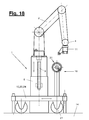
- FIG. 20 is a side schematic view showing another variant of the robot arrangement with a multiaxially movable carrying means at a column;
- FIG. 21 is a top schematic view showing another variant of the robot arrangement with a multiaxially movable carrying means at a column;
- FIG. 22 is a schematic view showing a design variant of a crank drive
- FIG. 23 is a schematic view showing another design variant of a crank drive
- FIG. 24 is a schematic view showing another design variant of a crank drive
- FIG. 25 is a schematic view showing another design variant of a crank drive
- FIG. 26 is a schematic view showing another design variant of a crank drive
- FIG. 27 is a schematic view showing another design variant of a crank drive
- FIG. 28 is a schematic view showing another design variant of a crank drive
- FIG. 29 is a schematic view showing another design variant of a crank drive
- FIG. 30 is a schematic view showing another design variant of a crank drive
- FIG. 31 is a schematic view showing one of different design variants of a carrying means of the robot arrangement
- FIG. 32 is a schematic view showing another of different design variants of a carrying means of the robot arrangement
- FIG. 33 is a schematic view showing another of different design variants of a carrying means of the robot arrangement.
- FIG. 34 is a schematic view showing another of different design variants of a carrying means of the robot arrangement
- FIG. 35 is a schematic view showing another of different design variants of a carrying means of the robot arrangement.
- FIG. 36 is a schematic view showing an exemplary embodiment with the interaction of a plurality of robot arrangements
- FIG. 37 is a schematic view showing one of different possibilities of motion and displacing motions of a robot arrangement
- FIG. 38 is a schematic view showing another of different possibilities of motion and displacing motions of a robot arrangement
- FIG. 39 is a schematic view showing another of different possibilities of motion and displacing motions of a robot arrangement
- FIG. 40 is a schematic view showing another of different possibilities of motion and displacing motions of a robot arrangement
- FIG. 41 is a schematic view showing another of different possibilities of motion and displacing motions of a robot arrangement
- FIG. 42 is a side schematic view showing a complex robot arrangement with an auxiliary device
- FIG. 43 is a top schematic view showing the complex robot arrangement with an auxiliary device
- FIG. 44 is a schematic view showing one of different operating positions of the robot arrangement from FIGS. 42 and 43 ;
- FIG. 45 is a schematic view showing another of different operating positions of the robot arrangement from FIGS. 42 and 43 ;
- FIG. 46 is a schematic view showing another of different operating positions of the robot arrangement from FIGS. 42 and 43 .
- the present invention pertains to a robot arrangement ( 1 ) and to a process for operating same.
- the robot arrangement ( 1 ) has a movable, programmable robot ( 2 ), which has a plurality of links ( 4 , 5 , 6 , 7 ) movably connected to one another and corresponding axes of motion (I-VII).
- the robot ( 2 ) is arranged on a movable carrying means (a movable carrying device) ( 15 ) and can carry out displacing or shifting motions (v) with this.
- a robot arrangement drive ( 16 ), which can be actuated by the robot ( 2 ), is provided for this for the carrying means ( 15 ).
- the robot arrangement drive ( 16 ) is actuated by a motion of the robot ( 2 ), especially by a displacing motion of the end link ( 4 ) of the robot.
- the robot arrangement ( 1 ) may have a positioning means ( 35 ) for locomotion or the displacing motion of the robot ( 2 ) and the carrying means ( 15 ) thereof.
- an external and relatively stationary, especially stationary counterforce support ( 30 ), which interacts with the drive means ( 27 ) for transmitting the driving forces exerted by the robot ( 2 ) and the driving motions to achieve said displacing motions (v), may be present for the robot arrangement drive ( 16 ).
- the positioning means ( 35 ) can interact with the counterforce support ( 30 ) or be combined with same.
- Various variants are likewise shown for the counterforce support ( 30 ) and the positioning means ( 35 ) in the exemplary embodiments.
- the carrying means ( 15 ) is arranged movably at or on a foundation ( 14 ) and can move in/along one direction or axis or in/along a plurality of directions or axes. These may be rotator and/or translatory axes of motion. Various embodiments are likewise available for the kinematics and the design embodiment of the carrying means ( 15 ).
- FIG. 1 shows a first embodiment of a robot arrangement ( 1 ) with a carrying means ( 15 ), which is designed as a carriage ( 20 ), which can roll with a plurality or rollers or wheels ( 21 ) on a foundation ( 14 ), e.g., a flat floor.
- the wheels ( 21 ) may be mounted at least partially pivotably, so that the carriage ( 20 ) can travel under the effect of the robot arrangement drive ( 16 ) in a straight line or in any desired curves as well as in any desired direction forward or backward and also turn on the spot.
- the carrying means ( 15 ) has a platform ( 24 ), on which the robot ( 2 ) and the wheels ( 21 ) are mounted.
- the carrying means ( 15 ) has, furthermore, a locking means ( 22 ), which may likewise be arranged on the platform ( 24 ) and with which the carrying means ( 15 ) can be locked.
- Locking means ( 22 ) may have, e.g., height-adjustable support feet. It can be actuated or activated and deactivated by the robot ( 2 ).
- locking means ( 22 ) may have a controllable adjusting robot arrangement drive.
- a supply means ( 17 ) may be arranged at the carrying means ( 15 ) in a suitable location, e.g., hanging under the platform ( 24 ).
- the supply means ( 17 ) may contain different components, e.g., an included electric supply means for a robot ( 2 ) in the form of a battery or the like.
- Supply means ( 17 ) may also contain a control unit for a robot ( 2 ).
- Supply means ( 17 ) may, furthermore, make available further operating materials, e.g., compressed air, hydraulic fluid, coolant or the like.
- FIG. 1 shows a preferred embodiment of the multilink robot ( 2 ), which has, e.g., seven axes of motion or robot axes (I-VII) here.
- the number of axes may also be lower or higher.
- the links ( 4 , 5 , 6 , 7 ) are connected to one another in an articulated manner by means of corresponding bearings and axis drives, forming rotator axes (I-VII).
- the robot ( 2 ) shown has power-controlled or power-regulated robot axes (I-VII) or axis drives along with a control and along with an associated sensor system (not shown) detecting acting loads.
- the robot ( 2 ) may have, moreover, at least one flexible robot axis (I-VII) with active compliance regulation, pure force regulation or with a combination of position and force regulation.
- the sensor system has, e.g., on some or all axes (I-VII), a torque sensor and is connected to the robot control. Said axes may also have, in addition, a controllable or switchable brake.
- the robot ( 2 ) has a basic link ( 7 ), which is mounted rotatably on the carrying means ( 15 ), forming a first robot axis (I).
- An intermediate link ( 6 ) is connected to the basic link ( 7 ) via the robot axis (II).
- the intermediate link ( 6 ) may be split and rotatable in itself about a central, longitudinally directed robot axis (III).
- the intermediate link ( 5 ) is connected via a robot axis (VI) to an end link ( 4 ), which is designed, e.g., as a robot hand and has a movable driven element ( 3 ), especially one rotating about an axis of rotation ( 10 ), and a tool ( 11 ), e.g., a controllable gripping tool, is arranged at said driven element.
- the axis of rotation ( 10 ) may form the robot axis ( 7 ).
- the robot ( 2 ) shown may be designed as a lightweight robot, which consists of lightweight materials, e.g., light metal and plastic and also has a small overall size. It may have a low weight and a correspondingly limited load-bearing capacity, which equals, e.g., up to 20 kg.
- the robot arrangement drive ( 16 ) and its drive means ( 27 ), which can be actuated by the robot ( 2 ), may have different design and kinematic embodiments.
- the drive means ( 27 ) is designed as a support means ( 28 ), which can be grasped and used by the robot ( 2 ) with a tool ( 11 ), e.g., a multifunctional gripping tool.
- the support means ( 28 ) is used to establish a force-absorbing contact with an external, relatively stationary counterforce support ( 30 ), which is not shown in FIG. 1 .
- the support means ( 28 ) is designed, e.g., as socket pin with an upright shaft and with a seat adapted to the gripping tool ( 11 ) at the upper end of the shaft. It is held detachably at the carrying means ( 15 ) by means of a suitable bracket.
- the carrying means ( 15 ) is designed as a sliding means or floating means ( 18 ), which is movable at or on a foundation ( 14 ) by means of, e.g., an air cushion, a spacing magnetic field or the like along various axes or directions. It can likewise be moved and guided on any desired straight or curved paths by the robot arrangement drive ( 16 ). Locking means ( 22 ) can be brought about here, e.g., by switching off an air cushion and depositing the carrying means ( 15 ).
- the design of the robot arrangement ( 1 ) may otherwise be the same as in FIG. 1 , and, in particular, the drive means ( 27 ) may be designed as a support means ( 28 ).
- FIG. 3 shows a variant to FIG. 1 with a carriage ( 20 ), in which the drive means ( 27 ) is designed as a driving drive, e.g., a crank drive ( 31 ), which is arranged at the carrying means ( 15 ) and is actuated by the robot ( 2 ) with a suitable tool ( 11 ) to generate a drive motion.
- a driving drive e.g., a crank drive ( 31 )
- a suitable tool ( 11 ) to generate a drive motion.
- This may be, e.g., the above-mentioned gripping tool ( 11 ), which has an extension arm or other similar means for detachable meshing with a crank.
- the robot ( 2 ) can grasp the crank and rotate it to generate a driving motion.
- the driving drive or crank drive ( 31 ) acts in this embodiment on the carrying means ( 15 ) and the relation thereof to the foundation ( 14 ) and rotatingly drives, e.g., one or more wheels ( 21 ). A relatively inaccurate or rough positioning of the robot ( 2 ) is thus given.
- the robot arrangement ( 1 ) with a carriage ( 20 ) and with another embodiment of a crank drive ( 31 ) is shown in the embodiment according to FIG. 4 . It interacts with a relatively stationary drive element ( 32 ), e.g., a belt arranged at the foundation ( 14 ), especially a toothed belt here. This permits more accurate positioning of the robot and the determination of the path of displacement (v). Further details will be explained below.
- a relatively stationary drive element e.g., a belt arranged at the foundation ( 14 ), especially a toothed belt here.
- FIGS. 5 through 8 illustrate the motion process of the robot arrangement ( 1 ) and of the robot arrangement drive ( 16 ) during the performance of a displacing or travel motion.
- FIG. 5 shows the starting position with the carrying means ( 5 ) locked.
- robot ( 2 ) grips the support means ( 28 ) and detaches it from the carrying means ( 15 ).
- the robot then assumes a stretched position according to FIG. 7 and brings the support means ( 28 ) with a counterforce support ( 30 ) on the foundation ( 14 ) into a force-transmitting meshing. This may happen by friction, adhesive or magnetic action, positive locking or the like.
- the locking means ( 22 ) is released.
- FIG. 8 shows this end position and the path of displacement or travel path (v) covered compared to FIG. 7 ).
- the robot ( 2 ) Based on its defined retracting motion, the robot ( 2 ) recognizes the path of displacement (v) and its end position according to FIG. 8 , especially when the counterforce support ( 30 ) has a known position and forms a positioning means ( 35 ) or interacts with this. Out of this end position, which may possibly be locked, the robot can then again assume a stretched position according to FIG. 7 and start the motion cycle all over again.
- the motions of the robot and the displacing motions (v) generated thereby can be controlled by the robot ( 2 ) in terms of direction and size.
- the robot ( 2 ) can also perform rotary motions on the platform ( 24 ) for a change in direction and can make changes in direction, especially drive in curves, by interacting with the counterforce support ( 30 ).
- FIGS. 9 through 13 illustrate different variants of a counterforce support ( 30 ) and of a positioning means ( 35 ) during the use of a support means ( 28 ).
- FIGS. 9 through 12 show a side view and a tilted bottom view.
- the counterforce support ( 30 ) is formed by friction.
- the support means ( 28 ) has a crossarm at the lower shaft end of the support means ( 28 ).
- the crossarm extends from the shaft end in different directions, here, e.g., to two opposite sides, and carries at its end a friction element each, which is pressed against the foundation ( 14 ) and forms the counterforce support ( 30 ).
- the rotated position of the support means ( 28 ) is also known and fixed due to the spaced friction elements.
- the reference point ( 36 ), at which the robot ( 2 ) positions the drive means or support means ( 27 , 28 ), is preset by the robot ( 2 ), and the position of the point in space on the foundation ( 14 ) is defined by the known starting position of the robot ( 2 ) and the known robot motion. Accuracy is limited, so that the robot ( 2 ) can position itself only roughly during its displacing motion (v) to a target location.
- a support means ( 28 ) similar to that in FIG. 9 is used in the variant according to FIG. 10 , and the friction elements at the ends of the crossarm are replaced here by controllable suction cups, controllable magnets or other similar adhering fixing means.
- the control and actuation may be performed out of the robot ( 2 ).
- the reference point ( 36 ) for the counterforce support ( 30 ) is preset by the robot ( 2 ) in this case as well.
- FIG. 11 shows a variant of the support means ( 28 ) and of the counterforce support ( 30 ) with a positive-locking interaction.
- the positioning means ( 35 ) is designed as an aligning means ( 37 ) here.
- the support means ( 28 ) has at the shaft end, e.g., a pin, which can be inserted into an opening acting as a counterforce support ( 30 ) in the foundation ( 14 ) with a plug-in fit.
- the opening forms a reference point ( 36 ) with known position on the foundation ( 14 ), so that the robot ( 2 ) can make its references on this basis and can exactly determine its position as well as the path of displacement (v).
- the pins and openings may be present as respective pluralities of pins and openings, and the pins my again be located on a crossarm at the lower shaft end.
- a defined rotated position of the support element ( 28 ) meshing with the counterforce support ( 30 ) can now be established and an aligning means ( 37 ) can be formed. This enhances the accuracy of positioning.
- the exemplary embodiment according to FIG. 12 shows a variant of the support means ( 28 ) and of the counterforce support ( 30 ) as well as of the aligning means ( 37 ).
- the openings ( 30 ) have, e.g., a rotationally symmetrical, especially cylindrical shape.
- an individual opening ( 30 ) is provided as a reference point ( 36 ), which has a non-rotationally symmetrical and, e.g., elongated shape.
- a pin, whose shape is correspondingly adapted and is, e.g., elongated, is provided at the lower shaft end of the support means ( 28 ).
- the foundation ( 14 ) in the embodiments according to FIGS. 9 through 12 is, e.g., the floor of a shop or the like. In the variants according to FIGS. 11 and 12 , the foundation ( 14 ) also forms a reference site ( 40 ) with a plurality of reference points ( 36 ) with defined and known position.
- the foundation ( 14 ) may also be designed, as an alternative, as a surface of a workpiece.
- the reference site ( 40 ) is, e.g., an upright wall to form the counterforce support ( 30 ).
- One or more reference points ( 36 ) according to FIGS. 11 and 12 may be present here along with aligning means ( 37 ).
- the counterforce support ( 30 ) is formed by openings in the wall.
- the counterforce supports ( 30 ) and the reference points ( 36 ) also form a positioning means ( 35 ) at the same time, with which the robot ( 2 ) can orient and position itself for performing the displacing motion (v).
- FIG. 14 shows a variant of the robot arrangement ( 1 ), which was already mentioned above, and of the robot arrangement drive ( 16 ).
- the carrying means ( 15 ) is designed as a sliding carriage ( 19 ) here and interacts with a relatively stationary, especially stationary guide ( 23 ), e.g., a guide track. Due to the robot arrangement drive ( 16 ), the robot ( 2 ) can move along the guide ( 23 ) in a controlled manner.
- FIG. 14 also illustrates the multiple arrangement of reference points ( 36 ) at a reference site ( 40 ), which is formed here, e.g., by a template, which is arranged on a workpiece with location reference.
- the reference site ( 40 ) may also be defined directly by a workpiece.
- the reference points ( 36 ) with the counterforce support ( 30 ) being formed here or with the positioning means ( 35 ) are arranged in the known position and distribution, and they are arranged, e.g., in a regular grid.
- the reference points ( 36 ) in the form of, e.g., round openings may also have an additional function as a positioning and guiding means for a processing tool ( 12 ) guided by the robot ( 2 ), especially a drilling tool, and have a defined location reference to the workpiece.
- FIG. 14 shows different motion positions that the robot ( 2 ) can assume during a displacing motion (v) with the robot arrangement drive ( 16 ).
- a plurality of robots ( 2 ) with sliding carriages ( 19 ) may also be arranged at the guide ( 23 ).
- FIG. 15 shows a variant for multiaxial displacing motions (v) in any desired direction of a robot arrangement ( 1 ), wherein the carrying means ( 15 ) is designed here, e.g., as a sliding means or floating means ( 18 ). It may be designed, e.g., as a sliding plate with a switchable magnet or suction element or with an air cushion with suction element for fixation and possibly combined with stripping brushes.
- the foundation ( 14 ) is formed, e.g., by the floor or a table plate or tooling plate.
- the foundation ( 14 ) may possibly also be designed in the manner described in connection with FIG. 14 as a reference site ( 40 ) as a template with reference points ( 36 ) in a positive-locking meshing.
- FIG. 15 shows as an example the different displacing motions or positions that the robot ( 2 ) with its carrying means ( 15 ) along with the robot arrangement drive ( 16 ) can perform and assume.
- FIGS. 16 and 17 show a variant of the robot arrangement ( 1 ) from FIG. 1 .
- the robot ( 2 ) is arranged here on a base ( 8 ) with a distance from the platform ( 24 ).
- the support means ( 28 ) has a correspondingly greater length of its shaft.
- the support means ( 28 ) is arranged at a guide ( 29 ) in this exemplary embodiment. This guide ( 29 ) is in turn fastened and mounted at the carrying means ( 15 ), especially at the platform ( 24 ).
- the guide ( 29 ) may have a plurality of arms and articulations, which impart a great and multiaxial mobility to the support means ( 28 ).
- the guide ( 29 ) is connected to the support means ( 28 ) permanently or optionally rotatably and meshes with the middle area thereof, wherein the forces of reaction or reaction moments generated during the drive motion are absorbed by the guide ( 29 ) and the release mechanism of the robot ( 2 ).
- the support means ( 28 ) may be received, with the guide retracted, near the base ( 8 ) in a recess of the platform ( 24 ).
- FIG. 18 shows a variant of the robot arrangement ( 1 ), in which the robot ( 2 ) has a position adjusting means ( 9 ) for a displacement relative to the platform ( 24 ).
- This is, e.g., a height adjusting means with a spindle and with a crank drive, which the robot ( 2 ) can actuate itself in order to bring itself into the desired position in height in a controlled manner and reference to the position.
- the robot ( 2 ) may again be arranged on a base ( 8 ) here.
- FIG. 18 also shows a correspondingly adapted crank drive ( 31 ), whose crank is arranged at a correspondingly high column in the working area of the robot ( 2 ). At least one of the wheels ( 21 ), which is rolling on a foundation ( 14 ), is driven here by means of the crank.
- the direction can be preset, e.g., by means of a guide, not shown.
- FIG. 19 shows a variant of the robot arrangement ( 1 ) on another foundation ( 14 ), which is designed here, e.g., as a workpiece ( 47 ).
- a workpiece This may be, e.g., the fuselage of an airplane or the hull of a ship.
- the workpiece ( 47 ) may have a contour of any desired shape and especially of any desired curvature.
- the carrying means ( 15 ) may be of any desired and suitable design, e.g., it may a carriage ( 20 ) with wheels or rollers ( 21 ), which roll on the surface of the workpiece.
- the drive means ( 27 ) is designed again as a crank drive ( 31 ), which interacts in this case with a relatively stationary drive element ( 32 ), here, e.g., a belt, especially toothed belt, which is arranged on the surface of the workpiece.
- the belt ( 30 ) may be tightened and also forms at the same time a guide ( 23 ) for the carrying means ( 15 ).
- the belt or toothed belt ( 32 ) is guided at the carrying means ( 15 ) via a driving wheel ( 33 ), especially a pinion, of the crank drive ( 31 ) located there.
- the robot ( 2 ) converts the driving wheel ( 33 ) motion into rotary motion with a crank, not shown.
- FIGS. 20 and 21 show another variant of the robot arrangement ( 1 ) in tilted views.
- the foundation ( 14 ) or the reference site ( 40 ) is designed as a frame or column here, which has a basic part, an upright and possibly height-adjustable support arm and a horizontal extension arm, on which the carrying means ( 15 ) with a robot ( 2 ) is arranged.
- the carrying means ( 15 ) is designed as a sliding carriage ( 19 ) here, which can perform multiaxial displacing motions (v). These may be a rotary motion about the, e.g., central axis of the extension arm and a linear travel motion along the extension arm.
- the sliding carriage ( 19 ) may have for this a rotating means with its base supported on the extension arm such that the base rotates in unison and with a turntable ring, on which the robot ( 2 ) is arranged.
- the drive means ( 27 ) may be designed as a crank drive ( 31 ) with a drive element ( 32 ) designed, e.g., as a toothed ring at the base and with a pinion ( 33 ).
- the robot ( 2 ) can again operate the crank for the crank drive ( 31 ) independently here.
- the robot ( 2 ) can use another drive means ( 27 ), e.g., the above-described support means ( 28 ), wherein the counterforce support ( 30 ) is formed for this by openings and reference points ( 36 ) on the extension arm. Due to this robot arrangement drive ( 16 ), the robot ( 2 ) can move to a workpiece ( 47 ), which has, e.g., a tubular shape and surrounds the robot ( 2 ) and the extension arm on the outside. Such an arrangement is suitable, e.g., for carrying out handling or machining processes or the like within the fuselage of an airplane or within the hull of a ship.
- FIGS. 22 through 30 show different variants for the design of a crank drive ( 31 ).
- FIG. 22 shows a crank drive ( 31 ) with a rotatable crank, which is arranged directly at a wheel ( 21 ) of a carrying means ( 15 ) with the same axis and drives same directly.
- the crank drive ( 23 ) is arranged with a vertical offset over the driven wheel ( 21 ), and a transmission may be inserted in-between for power transmission.
- FIG. 24 shows a crank drive ( 30 ) with a threaded spindle, by means of which a tightened spindle nut is moved axially for the purpose of the robot arrangement drive ( 16 ) or possibly also for position adjustment ( 9 ).
- FIG. 25 shows the crank drive ( 31 ) with a drive element ( 32 ), e.g., a toothed rack or worm shaft, with which a counterforce support ( 30 ) can be formed.
- a drive element 32
- a crank drive ( 31 ) is shown combined with a belt drive, wherein the relatively stationary drive element ( 32 ), forming a counterforce support ( 30 ), here a belt or toothed belt, is guided in an guide by means of tensioning and deflecting rollers over a driving wheel or pinion ( 33 ) with driving meshing.
- the driving wheel ( 33 ) is set into rotation by means of a crank of the crank drive ( 31 ) by the robot ( 2 ).
- Such an arrangement can be used in the embodiment according to FIG. 19 .
- FIGS. 27 through 30 show such a crank and belt drive arrangement in different other views.
- FIGS. 29 and 30 show here a securing means ( 34 ), which locks the crank drive ( 31 ) during non-actuation by the robot ( 2 ).
- the robot ( 2 ) must press in for this the crank disk arranged displaceably on the crank pin in the axial direction and now release radial serrations in relation to a surrounding, relatively stationary bearing housing.
- a resetting spring which again pushes the crank disk into said toothed meshing when the crank is released by the robot ( 2 ), is tensioned at the same time.
- the crank disk is guided for this on the crank pin axially displaceably and such that it rotates in unison.
- FIGS. 31 through 35 show different variants in the design of a platform ( 24 ) and of a carrying means ( 15 ). Different arrangements of wheels ( 21 ) are shown here as well. Corresponding designs may also be used for other sliding or floating means with air cushions, magnets, suction units or the like.
- the platforms may have a prismatic or round shape and outer contour. Openings for forming a C or H shape are also possible here.
- a platform ( 24 ) may have a conical shape at one site or at a plurality of sites.
- the number of wheels or sliding elements may equal, e.g., three or four.
- FIG. 36 shows a case of application in which a plurality of robot arrangements ( 1 ) of the above-described type interact for carrying out a process and position themselves for this at a work location, e.g., a workpiece, a table or another work station.
- the robot arrangements ( 1 ) have the above-described self propelling drives for the robot arrangement drive ( 16 ), with which the robot moves to the target location and reference site and positions itself in the process more or less accurately or roughly or finely.
- a correspondingly accurate positioning means ( 35 ) may be provided. This may designed, e.g., as a plotting means ( 38 ) for the positive-locking and detachable connection between a carrying means ( 15 ) and the reference site ( 40 ) or even of carrying means ( 15 ) among each other. With their sensitivity and the robot arrangement drive ( 26 ), the robots ( 1 ) can seek the corresponding plotting means ( 38 ) in a tactile manner and establish the positive-locking meshing for positioning and alignment.
- a carrying means ( 15 ) especially of the platform ( 24 ) thereof, which is shown in FIG. 35 , close positioning of the robot arrangements ( 1 ) and of the robots ( 2 ) thereof on the periphery of the reference site ( 40 ) or among others is possible.
- the robots ( 2 ) can all machine or handle the workpiece located at the reference site ( 40 ) or perform other processes thereon from a preset, exact position.
- FIGS. 37 through 41 schematically show different exemplary superimposed or shifting motions (v), which a robot arrangement ( 1 ) with the robot arrangement drive ( 16 ) can carry out.
- This is a linear motion in FIG. 37 , as it is also shown in FIGS. 5 through 8 .
- FIG. 38 shows a linear travel motion with increased stroke, in which case the robot ( 2 ) is supported at first pullingly and then pushingly at a counterforce support ( 30 ) or a reference point ( 36 ). The robot ( 2 ) now performs a 180° turn on the platform ( 24 ).
- FIG. 39 shows the carrying means ( 15 ) performs, in turn, a 180° turn.
- FIG. 40 shows another rotated position and pivoting motion (v).
- a curved shifting motion (v) with pivoting motion of the carrying means ( 15 ) and of the robot ( 2 ) is likewise shown in the variant of FIG. 41 .
- FIG. 41 shows, in addition, a variant of a positioning means ( 35 ) at a reference site ( 40 ).
- the positioning means ( 35 ) is designed here as a positive-locking, contoured mount ( 39 ) at the reference site ( 40 ), wherein the shape of the mount interacts with the outer contour of the carrying means ( 15 ), especially of the platform ( 24 ) thereof, in a positive-locking manner.
- the exemplary embodiment illustrates, besides, how a robot arrangement ( 1 ) with a curved shifting motion (v) can bypass an obstacle ( 41 ).
- the robot arrangement ( 1 ) with the robot being self propelling—the drive of the robot ( 2 ) forms a part of the robot arrangement drive ( 16 ) is shown in different variants in the above-described exemplary embodiments.
- the robot ( 2 ) can perform any desired processes at the workstation or at the site of use. It can use for this the gripping tool ( 11 ) already used for the robot arrangement drive ( 16 ). In such a case, the robot ( 2 ) performs primarily handling tasks.
- the tool ( 11 ) may also be of a multifunctional design and may also have, besides gripping elements, further functional and machining elements, e.g., the extension arm shown with gripping means for actuating the crank. Other functional elements may be joining elements or the like.
- the tool ( 11 ) may be arranged permanently at the end link ( 4 ), especially at the driven element ( 3 ) thereof.
- a change coupling ( 13 ) indicated in FIG. 1 which makes automatic tool change possible, may be arranged at the end link ( 4 ) or driven element ( 3 ).
- the robot ( 2 ) can expand the scope of processes it can perform as a result.
- FIGS. 42 through 46 illustrate a complex robot arrangement ( 1 ) outfitted to a higher level, in which the robot ( 2 ) can perform a plurality of different processes.
- the robot arrangement drive ( 16 ) may be designed corresponding to the previous exemplary embodiments.
- the variant according to FIGS. 42 through 46 illustrates, besides, further design variants of the robot arrangement ( 1 ).
- the robot ( 2 ) may have, e.g., a different and possibly additional type of position adjustment ( 9 ). It may be used for lateral adjustment on the platform surface and have a lockable floating frame ( 25 ).
- the robot ( 2 ) can be brought here into a variable position in relation to the workpiece ( 47 ) with the carrying means ( 15 ) positioned and locked and adjust itself in relation to a reference site located there.
- the robot ( 2 ) or an adjusting means can ensure locking of the floating frame ( 25 ).
- the exemplary embodiment illustrates, besides, a variant in tool design.
- the robot ( 2 ) carries here the gripping tool ( 11 ) described in the previous exemplary embodiments. This can possibly also grip and carry additional tools ( 12 ), besides a support means ( 28 ). These additional tools may be, e.g., handling and gripping tools for holding and guiding components ( 44 ) or machining tools or joining tools or the like.
- the gripping tool ( 11 ) is designed in such a case as a universal gripper, which has various gripping functions and can also function as a coupling means for picking up and operating additional tools.
- a deposit site ( 46 ) for one or more tools ( 12 ) may be present at the carrying means ( 15 ). In a variant of the embodiment shown, the above-mentioned change coupling may be present, with which the robot ( 2 ) can pick up the tools ( 12 ) directly and change them automatically.
- At least one additional, possibly detachable deposit site ( 45 ), which can be used, e.g., to receive the components ( 44 ) shown in the form of sheet metals, may be arranged at the carrying means ( 15 ).
- a deposit site ( 45 ) may also receive small parts such as screws or the like.
- an auxiliary device ( 42 ) which is movable and controllable and which can interact with the robot ( 2 ), is arranged on the carrying means ( 15 ) in the embodiment shown.
- the auxiliary device ( 42 ) can be used to support the process and can be used, e.g., to move and/or position a component ( 44 ).
- the auxiliary device ( 42 ) has for this, e.g., a frame with a plurality of possibly height-adjustable columns, at the ends of which holding or pressing-on elements ( 43 ) or other functional elements may be arranged, which possibly have an adjusting axis of their own and are likewise controllable.
- the auxiliary device ( 42 ) can be arranged together with the robot ( 2 ) on a floating frame ( 25 ) to secure a position reference.
- FIGS. 44 through 46 exemplarily illustrate the course of a function and process of such a robot arrangement ( 1 ), where a component ( 44 ) in the form of a cover shall be fastened at the opening ( 48 ) of a workpiece ( 47 ), e.g., of the fuselage of an airplane.
- the robot arrangement ( 1 ) with the robot arrangement drive ( 16 ) is moved to the intended site of use at the workpiece ( 47 ) and positioned as well as locked there.
- the robot ( 2 ) removes a component ( 44 ) from the deposit site ( 45 ) with its gripping tool ( 12 ).
- it moves the component ( 44 ) into the correct mounting position at the workpiece ( 47 ) and to the opening ( 48 ) thereof.
- the subsequently activated auxiliary device ( 42 ) holds the component ( 44 ) in this position and presses it against the workpiece ( 47 ).
- the robot ( 2 ) can then detach its handling tool ( 12 ) from the component ( 44 ) and replace it with another tool ( 12 ), e.g., a joining tool, with which it subsequently joins, e.g., rivets or screws, the component ( 44 ) being held in position according to FIG. 46 by the auxiliary device ( 42 ) to the workpiece ( 47 ).
- a joining tool e.g., rivets or screws
- the floating frame ( 25 ) may be useful during this positioning.
- the auxiliary device ( 42 ) can at first move out after receiving the component ( 44 ) from the robot ( 2 ) and position itself at the workpiece ( 47 ) on the basis of suitable reference points by means of the floating frame ( 25 ), and the robot ( 2 ) can also be brought into position at the same time.
- the floating frame ( 25 ) can then be locked.
- the robot arrangement drive ( 16 ) can again be used for the path of the robot arrangement ( 1 ) to the next intended site of use, e.g., assembly site, at the same workpiece ( 47 ).
- Complex multipart processes, especially handling, assembly or machining processes, at a plurality of sites of a workpiece ( 47 ) or at a provided multiple arrangement of workpieces ( 47 ) can also be automated in this manner.
- the carrying means ( 15 ) can also be moved by a worker by hand or with a coupled tow drive.
- a plurality of robots ( 2 ) may be arranged on a carrying means ( 15 ), and one or more robots may be used for the robot arrangement drive ( 16 ).
- a robot ( 2 ) may have any other desired and suitable design and may have position-controlled axes. The number, design and combination of the robot axes can be selected as desired, and these axes, in particular, may be designed as translatory and/or rotator axes.
- the robot arrangement ( 1 ) may have, furthermore, another type of carrying supplies.
- the operating materials, especially power and signal currents, fluids and the like, can be carried out by means of a trailing line, sliding contacts or path contacts or the like during the displacing motion (v). Furthermore, docking at different supply sites is possible.
- the carrying means ( 15 ) may be arranged hanging on a ceiling or on a wall in case of a suitable design and moved along here.
- a tool ( 11 , 12 ) may be movable and controllable, and the actuation and the supply with operating materials takes place from the robot ( 2 ).
- supply with operating materials may take place from the outside.
- the drive means ( 27 ) may likewise be modified.
- the robot ( 2 ) When the robot ( 2 ) is temporarily holding on to a counterforce support ( 30 ), it can use for this, e.g., its gripping tool ( 11 ) and grip external, relatively stationary reference points ( 36 ) in the form of projections.
- a driving drive ( 31 ) may be designed as a ratchet drive with oscillating driving motion, e.g., similarly to a gang car, or in another suitable manner.
- an external sensor system e.g., a camera measuring system or vision system, may be used in conjunction with the robot control.
- a preferred area of use of the robot arrangement ( 1 ) is in vehicle manufacturing plants, especially in body shell plants or assembly. Other possibilities of use are in logistic systems, e.g., in high-bay warehouses, in supermarkets or the like.
- a robot ( 2 ) provided with sensitivity also offers here advantages concerning safety against accidents and collisions.
Landscapes
- Engineering & Computer Science (AREA)
- Robotics (AREA)
- Mechanical Engineering (AREA)
- Health & Medical Sciences (AREA)
- Nursing (AREA)
- Life Sciences & Earth Sciences (AREA)
- Animal Behavior & Ethology (AREA)
- General Health & Medical Sciences (AREA)
- Public Health (AREA)
- Veterinary Medicine (AREA)
- Manipulator (AREA)
Applications Claiming Priority (3)
| Application Number | Priority Date | Filing Date | Title |
|---|---|---|---|
| DE202012100646U | 2012-02-27 | ||
| DE202012100646.4 | 2012-02-27 | ||
| DE202012100646U DE202012100646U1 (de) | 2012-02-27 | 2012-02-27 | Roboteranordnung |
Publications (2)
| Publication Number | Publication Date |
|---|---|
| US20130226341A1 US20130226341A1 (en) | 2013-08-29 |
| US9149927B2 true US9149927B2 (en) | 2015-10-06 |
Family
ID=47749684
Family Applications (1)
| Application Number | Title | Priority Date | Filing Date |
|---|---|---|---|
| US13/776,870 Expired - Fee Related US9149927B2 (en) | 2012-02-27 | 2013-02-26 | Robot arrangement |
Country Status (3)
| Country | Link |
|---|---|
| US (1) | US9149927B2 (de) |
| EP (1) | EP2631042A3 (de) |
| DE (1) | DE202012100646U1 (de) |
Cited By (5)
| Publication number | Priority date | Publication date | Assignee | Title |
|---|---|---|---|---|
| US9789610B1 (en) * | 2015-09-02 | 2017-10-17 | X Development Llc | Safe path planning for collaborative robots |
| JP2018069430A (ja) * | 2016-11-04 | 2018-05-10 | トヨタ自動車株式会社 | ロボットの制御方法 |
| US20190091862A1 (en) * | 2017-09-27 | 2019-03-28 | Shahram RASHVAND | Movable robat in construction industries |
| CN112823082A (zh) * | 2018-10-12 | 2021-05-18 | 克朗斯股份公司 | 使用机器人系统的方法和用于容器处理设施的机器人系统 |
| US11254015B2 (en) | 2019-09-24 | 2022-02-22 | Thermo Crs Ltd. | Multi-axis gripper for lab automation robot |
Families Citing this family (39)
| Publication number | Priority date | Publication date | Assignee | Title |
|---|---|---|---|---|
| JP6255724B2 (ja) * | 2013-06-10 | 2018-01-10 | セイコーエプソン株式会社 | ロボットおよびロボットの操作方法 |
| US9902447B2 (en) * | 2013-07-12 | 2018-02-27 | University Of Technology, Sydney | Adhesion system for a climbing vehicle |
| DE202013105203U1 (de) | 2013-11-18 | 2015-02-19 | Kuka Systems Gmbh | Arbeitsvorrichtung |
| DE102014200760A1 (de) * | 2014-01-17 | 2015-07-23 | Siemens Aktiengesellschaft | Läuferschwenksystem |
| CN104803297B (zh) * | 2014-01-23 | 2016-12-07 | 北大方正集团有限公司 | 一种塔吊装置以及一种大束流离子注入设备 |
| US9937549B2 (en) * | 2014-07-09 | 2018-04-10 | The Boeing Company | Two-stage riveting |
| CN104647354A (zh) * | 2014-12-25 | 2015-05-27 | 广西大学 | 一种多自由度可控机构式混联搬运机器人 |
| CN104647335A (zh) * | 2014-12-25 | 2015-05-27 | 广西大学 | 一种可控多连杆搬运机器人 |
| DE202015105201U1 (de) | 2015-10-02 | 2017-01-09 | Kuka Systems Gmbh | Medienversorgung für autark bewegliche Manipulatoren |
| DE102015220066A1 (de) * | 2015-10-15 | 2017-04-20 | Kuka Roboter Gmbh | Haptisches Referenzieren eines Manipulators |
| DE102015120058B3 (de) * | 2015-11-19 | 2017-03-02 | Kuka Roboter Gmbh | Ankoppeleinrichtung und Verfahren zum Ankoppeln einer mobilen Prozesseinrichtung |
| CN105500330B (zh) * | 2015-12-01 | 2018-01-12 | 南陵旺科知识产权运营有限公司 | 无人驾驶的机电一体化的运输车 |
| DE102016201530A1 (de) * | 2016-02-02 | 2017-08-03 | Deutsches Zentrum für Luft- und Raumfahrt e.V. | Andockstation für mobile Roboter sowie Verfahren zum Betreiben eines mobilen Roboters |
| DE102016201687A1 (de) * | 2016-02-04 | 2017-08-10 | Robomotion Gmbh | System sowie Verfahren zum Positionieren einer Roboterzelle relativ zu einem Arbeitsplatz |
| US9827677B1 (en) * | 2016-05-16 | 2017-11-28 | X Development Llc | Robotic device with coordinated sweeping tool and shovel tool |
| US9827678B1 (en) * | 2016-05-16 | 2017-11-28 | X Development Llc | Kinematic design for robotic arm |
| US10052764B2 (en) * | 2016-06-16 | 2018-08-21 | Toyota Motor Engineering & Manufacutring North America, Inc. | Automated and adjustable platform surface |
| EP3263087B1 (de) * | 2016-06-29 | 2021-03-10 | Fundación Tecnalia Research & Innovation | Tragbare vorrichtung zur rehabilitation der oberen gliedmassen |
| AU2017294796B2 (en) | 2016-07-15 | 2019-05-30 | Fastbrick Ip Pty Ltd | Brick/block laying machine incorporated in a vehicle |
| AU2017294795B2 (en) | 2016-07-15 | 2019-06-13 | Fastbrick Ip Pty Ltd | Boom for material transport |
| JP6571618B2 (ja) * | 2016-09-08 | 2019-09-04 | ファナック株式会社 | 人間協調型ロボット |
| US11439531B2 (en) * | 2017-05-03 | 2022-09-13 | Danny GOEL | Orthopedic shoulder brace |
| AU2018295572B2 (en) | 2017-07-05 | 2022-09-29 | Fastbrick Ip Pty Ltd | Real time position and orientation tracker |
| US10646993B1 (en) * | 2017-07-26 | 2020-05-12 | Facebook, Inc. | Robots linkable to perform tasks in coordinated teams |
| CN111213098B (zh) | 2017-08-17 | 2024-03-15 | 快砖知识产权私人有限公司 | 用于交互系统的通信系统 |
| US11401115B2 (en) | 2017-10-11 | 2022-08-02 | Fastbrick Ip Pty Ltd | Machine for conveying objects and multi-bay carousel for use therewith |
| CN107811797B (zh) * | 2017-11-10 | 2023-09-26 | 中国人民解放军总医院 | 骨科机器人 |
| US11162241B2 (en) * | 2018-03-27 | 2021-11-02 | Deere & Company | Controlling mobile machines with a robotic attachment |
| CN108544464B (zh) * | 2018-04-24 | 2020-11-10 | 义乌市凡特塑料制品有限公司 | 一种基于超市购物以及机器人的隐蔽式智能物品放置系统 |
| DE102018207826A1 (de) * | 2018-05-18 | 2019-11-21 | Kuka Deutschland Gmbh | Handhabung, insbesondere, Transport von Gütern, insbesondere Wafern, durch einen Roboter |
| JP7141040B2 (ja) * | 2018-09-07 | 2022-09-22 | 川崎重工業株式会社 | 走行ロボット |
| DE102018217471A1 (de) * | 2018-10-12 | 2020-04-16 | Krones Ag | Modulares Robotersystem für eine Behälterverarbeitungsanlage |
| US11059534B2 (en) * | 2018-12-18 | 2021-07-13 | GM Global Technology Operations LLC | Nondeterministic assembly system and method |
| CN109454622A (zh) * | 2018-12-26 | 2019-03-12 | 莱森姆智能科技(常州)有限公司 | 一种移动式机器人平台及其工作方法 |
| US11633848B2 (en) | 2019-07-31 | 2023-04-25 | X Development Llc | Independent pan of coaxial robotic arm and perception housing |
| JP7382597B2 (ja) * | 2019-11-28 | 2023-11-17 | 川崎重工業株式会社 | ロボットシステムおよびロボットセル |
| DE102020117455A1 (de) | 2020-07-02 | 2022-01-05 | Bayerische Motoren Werke Aktiengesellschaft | Handhabungseinrichtung für eine Herstellungsumgebung |
| DE102020127501B3 (de) | 2020-10-19 | 2022-03-24 | Deutsches Zentrum für Luft- und Raumfahrt e.V. | Verfahren zum Erweitern des erreichbaren Arbeitsraums eines Roboterarms sowie Robotersystem |
| CN112402118B (zh) * | 2020-11-19 | 2022-06-07 | 中国人民解放军陆军特色医学中心 | 一种野外急救用的担架机器人 |
Citations (17)
| Publication number | Priority date | Publication date | Assignee | Title |
|---|---|---|---|---|
| US4993913A (en) | 1988-07-15 | 1991-02-19 | Nihon Biso Kabushiki Kaisha | Robot for a work on a wall surface |
| US5318254A (en) * | 1991-06-28 | 1994-06-07 | Conceptual Solutions, Inc. | Aircraft maintenance robot |
| US5858111A (en) * | 1997-01-21 | 1999-01-12 | Marrero; Lou | Aircraft maintenance apparatus and method of maintaining same |
| DE19816893A1 (de) | 1998-04-16 | 1999-11-04 | Fraunhofer Ges Forschung | Mobiles Robotersystem |
| DE19918272A1 (de) | 1999-04-22 | 2000-10-26 | Abb Patent Gmbh | Verfahren und Einrichtung zum Bewegen eines Industrieroboters entlang einer Fahrachse |
| EP1110679A1 (de) | 1999-03-10 | 2001-06-27 | Mitsubishi Heavy Industries, Ltd. | Arbeitsroboter |
| US6477730B1 (en) * | 1997-01-21 | 2002-11-12 | Omnics, Inc. | Aircraft maintenance apparatus and method of maintaining aircraft |
| US20040093650A1 (en) * | 2000-12-04 | 2004-05-13 | Martins Goesta | Robot system |
| US20040182960A1 (en) * | 2003-03-04 | 2004-09-23 | Ash Equipment Company, Inc. Doing Business As American Hydro Inc. | Dual nozzle hydro-demolition system |
| US20050029029A1 (en) * | 2002-08-30 | 2005-02-10 | Aethon, Inc. | Robotic cart pulling vehicle |
| US20050126144A1 (en) * | 2003-12-12 | 2005-06-16 | Vision Robotics Corporation | Robot mechanical picker system and method |
| DE102004016345A1 (de) | 2004-04-02 | 2005-10-20 | Fraunhofer Ges Forschung | Mobiler Roboter für die Ausführung unterschiedlicher Grundfunktionen |
| US20080154538A1 (en) * | 2006-10-21 | 2008-06-26 | Sam Stathis | System for accurately and precisely locating and marking a position in space using wireless communications and robotics |
| US20100106298A1 (en) * | 2008-10-27 | 2010-04-29 | Eusebio Guillermo Hernandez | Outdoor home cleaning robot |
| US20110017030A1 (en) * | 2009-01-16 | 2011-01-27 | Paul Chambers | Universal cutting tool for use with legacy and new generation explosive ordinance disposal (eod) robots |
| US20110137458A1 (en) * | 2008-12-26 | 2011-06-09 | Masujiro Hisatani | Cleaning robot system and method of controlling same |
| US20120036676A9 (en) * | 2008-09-04 | 2012-02-16 | Kawasaki Jukogyo Kabushiki Kaisha | Cleaning device for sunlight collecting devices in a solar thermal electric power generation system |
-
2012
- 2012-02-27 DE DE202012100646U patent/DE202012100646U1/de not_active Expired - Lifetime
-
2013
- 2013-02-22 EP EP13156290.2A patent/EP2631042A3/de not_active Withdrawn
- 2013-02-26 US US13/776,870 patent/US9149927B2/en not_active Expired - Fee Related
Patent Citations (19)
| Publication number | Priority date | Publication date | Assignee | Title |
|---|---|---|---|---|
| US4993913A (en) | 1988-07-15 | 1991-02-19 | Nihon Biso Kabushiki Kaisha | Robot for a work on a wall surface |
| US5318254A (en) * | 1991-06-28 | 1994-06-07 | Conceptual Solutions, Inc. | Aircraft maintenance robot |
| US5490646A (en) * | 1991-06-28 | 1996-02-13 | Conceptual Solutions, Inc. | Aircraft maintenance robot |
| US6477730B1 (en) * | 1997-01-21 | 2002-11-12 | Omnics, Inc. | Aircraft maintenance apparatus and method of maintaining aircraft |
| US5858111A (en) * | 1997-01-21 | 1999-01-12 | Marrero; Lou | Aircraft maintenance apparatus and method of maintaining same |
| DE19816893A1 (de) | 1998-04-16 | 1999-11-04 | Fraunhofer Ges Forschung | Mobiles Robotersystem |
| US6675068B1 (en) | 1999-03-10 | 2004-01-06 | Mitsubishi Heavy Industries, Ltd. | Working robot |
| EP1110679A1 (de) | 1999-03-10 | 2001-06-27 | Mitsubishi Heavy Industries, Ltd. | Arbeitsroboter |
| DE19918272A1 (de) | 1999-04-22 | 2000-10-26 | Abb Patent Gmbh | Verfahren und Einrichtung zum Bewegen eines Industrieroboters entlang einer Fahrachse |
| US20040093650A1 (en) * | 2000-12-04 | 2004-05-13 | Martins Goesta | Robot system |
| US20050029029A1 (en) * | 2002-08-30 | 2005-02-10 | Aethon, Inc. | Robotic cart pulling vehicle |
| US20040182960A1 (en) * | 2003-03-04 | 2004-09-23 | Ash Equipment Company, Inc. Doing Business As American Hydro Inc. | Dual nozzle hydro-demolition system |
| US20050126144A1 (en) * | 2003-12-12 | 2005-06-16 | Vision Robotics Corporation | Robot mechanical picker system and method |
| DE102004016345A1 (de) | 2004-04-02 | 2005-10-20 | Fraunhofer Ges Forschung | Mobiler Roboter für die Ausführung unterschiedlicher Grundfunktionen |
| US20080154538A1 (en) * | 2006-10-21 | 2008-06-26 | Sam Stathis | System for accurately and precisely locating and marking a position in space using wireless communications and robotics |
| US20120036676A9 (en) * | 2008-09-04 | 2012-02-16 | Kawasaki Jukogyo Kabushiki Kaisha | Cleaning device for sunlight collecting devices in a solar thermal electric power generation system |
| US20100106298A1 (en) * | 2008-10-27 | 2010-04-29 | Eusebio Guillermo Hernandez | Outdoor home cleaning robot |
| US20110137458A1 (en) * | 2008-12-26 | 2011-06-09 | Masujiro Hisatani | Cleaning robot system and method of controlling same |
| US20110017030A1 (en) * | 2009-01-16 | 2011-01-27 | Paul Chambers | Universal cutting tool for use with legacy and new generation explosive ordinance disposal (eod) robots |
Cited By (6)
| Publication number | Priority date | Publication date | Assignee | Title |
|---|---|---|---|---|
| US9789610B1 (en) * | 2015-09-02 | 2017-10-17 | X Development Llc | Safe path planning for collaborative robots |
| JP2018069430A (ja) * | 2016-11-04 | 2018-05-10 | トヨタ自動車株式会社 | ロボットの制御方法 |
| US20190091862A1 (en) * | 2017-09-27 | 2019-03-28 | Shahram RASHVAND | Movable robat in construction industries |
| CN112823082A (zh) * | 2018-10-12 | 2021-05-18 | 克朗斯股份公司 | 使用机器人系统的方法和用于容器处理设施的机器人系统 |
| US20210339383A1 (en) * | 2018-10-12 | 2021-11-04 | Krones Ag | Method for using a robot system and robot system for a container processing facility |
| US11254015B2 (en) | 2019-09-24 | 2022-02-22 | Thermo Crs Ltd. | Multi-axis gripper for lab automation robot |
Also Published As
| Publication number | Publication date |
|---|---|
| DE202012100646U1 (de) | 2013-06-04 |
| EP2631042A3 (de) | 2014-11-26 |
| EP2631042A2 (de) | 2013-08-28 |
| US20130226341A1 (en) | 2013-08-29 |
Similar Documents
| Publication | Publication Date | Title |
|---|---|---|
| US9149927B2 (en) | Robot arrangement | |
| US7476072B2 (en) | Transport apparatus | |
| CN108290283B (zh) | 联接装置和联接方法 | |
| CN103481279A (zh) | 多自由度机械手夹具 | |
| CN113043305B (zh) | 一种物料搬运的转运机械手 | |
| CN202656185U (zh) | 多自由度机械手夹具 | |
| CN114013975B (zh) | 一种多自由度货物翻转转运装置 | |
| US9446905B2 (en) | Feed device and method | |
| KR20170098892A (ko) | 생산 시스템 | |
| CN101952161A (zh) | 安装车辆仪表盘的装置和方法 | |
| JP6375428B2 (ja) | 自動処理システム、及びそれを配置するための装置 | |
| EP1611994B1 (de) | Werkzeugmaschine mit Palettenwechselfunktion sowie Verfahren zum Palettenwechsel | |
| CN214265627U (zh) | 一种基于防滑抓紧技术的机械手夹机构 | |
| CN108032277A (zh) | 带有升降机构的机器人 | |
| CN113459072B (zh) | 一种可切换式串并联多臂抓取无人机设计 | |
| CN117485422A (zh) | 一种用于风电叶片的主动转向转运车及风电叶片转运方法 | |
| JP2000198091A (ja) | 複数腕協調ロボットシステム | |
| CN211220697U (zh) | 新型智能机器人设备 | |
| CN112224732B (zh) | 机器人 | |
| CN109176459B (zh) | 多功能吸附式移动平台 | |
| JP2002036154A (ja) | 自立型ワーク移送装置 | |
| CN216736407U (zh) | 一种搬运机器人 | |
| CN207632353U (zh) | 一种手动机械手 | |
| JP4958069B2 (ja) | 搬送ロボット及び3自由度パラレルリンク機構 | |
| CN217966994U (zh) | 一种光伏组件配置设备 |
Legal Events
| Date | Code | Title | Description |
|---|---|---|---|
| AS | Assignment |
Owner name: KUKA SYSTEMS GMBH, GERMANY Free format text: ASSIGNMENT OF ASSIGNORS INTEREST;ASSIGNOR:STURM, THOMAS;REEL/FRAME:029874/0521 Effective date: 20130214 |
|
| STCF | Information on status: patent grant |
Free format text: PATENTED CASE |
|
| MAFP | Maintenance fee payment |
Free format text: PAYMENT OF MAINTENANCE FEE, 4TH YEAR, LARGE ENTITY (ORIGINAL EVENT CODE: M1551); ENTITY STATUS OF PATENT OWNER: LARGE ENTITY Year of fee payment: 4 |
|
| FEPP | Fee payment procedure |
Free format text: MAINTENANCE FEE REMINDER MAILED (ORIGINAL EVENT CODE: REM.); ENTITY STATUS OF PATENT OWNER: LARGE ENTITY |
|
| LAPS | Lapse for failure to pay maintenance fees |
Free format text: PATENT EXPIRED FOR FAILURE TO PAY MAINTENANCE FEES (ORIGINAL EVENT CODE: EXP.); ENTITY STATUS OF PATENT OWNER: LARGE ENTITY |
|
| STCH | Information on status: patent discontinuation |
Free format text: PATENT EXPIRED DUE TO NONPAYMENT OF MAINTENANCE FEES UNDER 37 CFR 1.362 |
|
| FP | Lapsed due to failure to pay maintenance fee |
Effective date: 20231006 |