US8995885B2 - Image forming apparatus and toner case - Google Patents
Image forming apparatus and toner case Download PDFInfo
- Publication number
- US8995885B2 US8995885B2 US13/897,182 US201313897182A US8995885B2 US 8995885 B2 US8995885 B2 US 8995885B2 US 201313897182 A US201313897182 A US 201313897182A US 8995885 B2 US8995885 B2 US 8995885B2
- Authority
- US
- United States
- Prior art keywords
- lever
- main body
- cover
- toner
- stopper
- Prior art date
- Legal status (The legal status is an assumption and is not a legal conclusion. Google has not performed a legal analysis and makes no representation as to the accuracy of the status listed.)
- Active, expires
Links
- 230000002452 interceptive effect Effects 0.000 claims abstract description 16
- 230000008878 coupling Effects 0.000 claims description 29
- 238000010168 coupling process Methods 0.000 claims description 29
- 238000005859 coupling reaction Methods 0.000 claims description 29
- 230000005540 biological transmission Effects 0.000 claims description 20
- 238000003756 stirring Methods 0.000 claims description 13
- 230000002787 reinforcement Effects 0.000 claims description 6
- 238000007599 discharging Methods 0.000 abstract description 3
- 238000011161 development Methods 0.000 description 9
- 238000010586 diagram Methods 0.000 description 8
- 238000004891 communication Methods 0.000 description 5
- 238000000034 method Methods 0.000 description 5
- 238000004806 packaging method and process Methods 0.000 description 3
- 230000008901 benefit Effects 0.000 description 2
- 238000004140 cleaning Methods 0.000 description 2
- 230000003247 decreasing effect Effects 0.000 description 2
- 238000003780 insertion Methods 0.000 description 2
- 230000037431 insertion Effects 0.000 description 2
- 239000005022 packaging material Substances 0.000 description 2
- 238000007639 printing Methods 0.000 description 2
- 230000008569 process Effects 0.000 description 2
- 238000007789 sealing Methods 0.000 description 2
- 238000012546 transfer Methods 0.000 description 2
- 230000008859 change Effects 0.000 description 1
- 238000003384 imaging method Methods 0.000 description 1
- 238000010348 incorporation Methods 0.000 description 1
- 238000009434 installation Methods 0.000 description 1
- 239000004973 liquid crystal related substance Substances 0.000 description 1
- 238000012856 packing Methods 0.000 description 1
- 239000002985 plastic film Substances 0.000 description 1
- 238000003825 pressing Methods 0.000 description 1
Images


Classifications
-
- G—PHYSICS
- G03—PHOTOGRAPHY; CINEMATOGRAPHY; ANALOGOUS TECHNIQUES USING WAVES OTHER THAN OPTICAL WAVES; ELECTROGRAPHY; HOLOGRAPHY
- G03G—ELECTROGRAPHY; ELECTROPHOTOGRAPHY; MAGNETOGRAPHY
- G03G15/00—Apparatus for electrographic processes using a charge pattern
- G03G15/06—Apparatus for electrographic processes using a charge pattern for developing
- G03G15/08—Apparatus for electrographic processes using a charge pattern for developing using a solid developer, e.g. powder developer
- G03G15/0822—Arrangements for preparing, mixing, supplying or dispensing developer
- G03G15/0877—Arrangements for metering and dispensing developer from a developer cartridge into the development unit
- G03G15/0881—Sealing of developer cartridges
- G03G15/0882—Sealing of developer cartridges by a peelable sealing film
-
- G03G15/0841—
-
- G—PHYSICS
- G03—PHOTOGRAPHY; CINEMATOGRAPHY; ANALOGOUS TECHNIQUES USING WAVES OTHER THAN OPTICAL WAVES; ELECTROGRAPHY; HOLOGRAPHY
- G03G—ELECTROGRAPHY; ELECTROPHOTOGRAPHY; MAGNETOGRAPHY
- G03G15/00—Apparatus for electrographic processes using a charge pattern
- G03G15/06—Apparatus for electrographic processes using a charge pattern for developing
- G03G15/08—Apparatus for electrographic processes using a charge pattern for developing using a solid developer, e.g. powder developer
- G03G15/0822—Arrangements for preparing, mixing, supplying or dispensing developer
- G03G15/0877—Arrangements for metering and dispensing developer from a developer cartridge into the development unit
- G03G15/0881—Sealing of developer cartridges
- G03G15/0886—Sealing of developer cartridges by mechanical means, e.g. shutter, plug
-
- G—PHYSICS
- G03—PHOTOGRAPHY; CINEMATOGRAPHY; ANALOGOUS TECHNIQUES USING WAVES OTHER THAN OPTICAL WAVES; ELECTROGRAPHY; HOLOGRAPHY
- G03G—ELECTROGRAPHY; ELECTROPHOTOGRAPHY; MAGNETOGRAPHY
- G03G21/00—Arrangements not provided for by groups G03G13/00 - G03G19/00, e.g. cleaning, elimination of residual charge
- G03G21/16—Mechanical means for facilitating the maintenance of the apparatus, e.g. modular arrangements
- G03G21/1604—Arrangement or disposition of the entire apparatus
- G03G21/1623—Means to access the interior of the apparatus
- G03G21/1633—Means to access the interior of the apparatus using doors or covers
Definitions
- the present disclosure relates to an image forming apparatus and a toner case installed to the image forming apparatus.
- An electrographic image forming apparatus carries out the development process by supplying a toner (a developer) from a development device to an electrostatic latent image formed on the surface of a photosensitive drum or the like.
- the toner used in such development process is supplied from a toner case configured to be attachable and detachable to an apparatus main body of the image forming apparatus.
- the above-mentioned toner case includes a case main body having a discharge port discharging the toner and a shutter opening/closing the discharge port.
- the shutter rotatably installed to the case main body and opening/closing the discharge port in accordance with the rotation is known.
- a locking member attached to the toner case locks the shutter in a closing state, thereby preventing the toner from leaking from the toner case during transport of the toner case.
- the above-mentioned technique is provided presupposing the transport of single toner case.
- the toner case is separately packed from the apparatus main body, and accordingly, the capacity and number of the packaging material are unnecessarily increased, thereby incurring an increase of a packaging cost.
- the imaging forming apparatus including the tone case configured as mentioned above, there is a fear that the toner case is installed, in a situation of the shutter closing the discharge port, to the apparatus main body by operation mistake of a worker, such as a user.
- a technique mentioned above does not take measures for solving the fear and it is difficult to prevent the operation mistake of the worker.
- an image forming apparatus includes a toner case, an apparatus main body and a cover.
- the toner case is configured to include a case main body having a discharge port configured to discharge a toner, a shutter configured to open/close the discharge port, and a lever connected with the shutter.
- the toner case is attachably/detachably installed.
- the cover is openably/closably attached to the apparatus main body and configured to cover at least a part of the toner case.
- the lever is configured to be shifted to a first position in order to make the shutter close the discharge port and to allow the close of the cover without interfering with the cover, to a second position in order to make the shutter close the discharge port and to interfere with the cover, or to a third position in order to make the shutter open the discharge port and to allow the close of the cover without interfering with the cover.
- a toner case is attachably/detachably installed to an apparatus main body of an image forming apparatus and covered by a cover openably/closably attached to the apparatus main body.
- the toner case includes a case main body, a shutter and a lever.
- the case main body has a discharge port configured to discharge a toner.
- the shutter is configured to open/close the discharge port.
- the lever is configured to connect with the shutter and to be shifted to a first position in order to make the shutter close the discharge port and to allow the close of the cover without interfering with the cover, to a second position in order to make the shutter close the discharge port and to interfere with the cover, or to a third position in order to make the shutter open the discharge port and to allow the close of the cover without interfering with the cover.
- FIG. 1 is a schematic diagram schematically showing a printer according to an embodiment of the present disclosure.
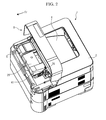
- FIG. 2 is a perspective view showing the printer in a situation, in which an upper cover is opened, according to the embodiment of the present disclosure.
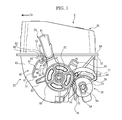
- FIG. 3 is a right top perspective view showing a toner container in the printer according to the embodiment of the present disclosure.
- FIG. 4 is a back perspective sectional view showing the toner container in the printer according to the embodiment of the present disclosure.
- FIG. 5 is an exploded perspective view showing the toner container in the printer according to the embodiment of the present disclosure.
- FIG. 6 is a front right perspective view showing the toner container in a situation, in which a lever is detached from a case main body, in the printer according to the embodiment of the present disclosure.
- FIG. 7 is a right side view showing the toner container in the printer according to the embodiment of the present disclosure.
- FIG. 8 is a perspective view showing the printer in a situation, in which the upper cover is closed, according to the embodiment of the present disclosure.
- FIG. 9A is a right side view showing the toner container in a situation, in which the lever is located at a first position, in the printer according to the embodiment of the present disclosure.
- FIG. 9B is a right side view showing the toner container in another situation, in which the lever is located at a second position, in the printer according to the embodiment of the present disclosure.
- FIG. 9C is a right side view showing the toner container in a further situation, in which the lever is located at a third position, in the printer according to the embodiment of the present disclosure.
- FIG. 10A is a bottom perspective view showing the toner container in a situation, in which the lever is located at the first position, in the printer according to the embodiment of the present disclosure.
- FIG. 10B is a bottom perspective view showing the toner container in another situation, in which the lever is located at the second position, in the printer according to the embodiment of the present disclosure.
- FIG. 10C is a bottom perspective view showing the toner container in a further situation, in which the lever is located at the third position, in the printer according to the embodiment of the present disclosure.
- FIG. 11A is a schematic diagram showing the toner container in a situation, in which a gripper of the lever engages with a stopper, in the printer according to the embodiment of the present disclosure.
- FIG. 11B is a schematic diagram showing the toner container in a another situation, in which the gripper of the lever is going to be shifted from an engaging state with the stopper to a released state, in the printer according to the embodiment of the present disclosure.
- FIG. 11C is a schematic diagram showing the toner container in a further situation, in which the engagement of the gripper of the lever with a stopper is released, in the printer according to the embodiment of the present disclosure.
- FIG. 12A is a side view showing a transmission coupling in the printer according to the embodiment of the present disclosure.
- FIG. 12B is a side view showing a roughly fan-formed transmission coupling in the printer according to another embodiment of the present disclosure.
- FIG. 12C is a side view showing a roughly arc-formed transmission coupling in the printer according to a further embodiment of the present disclosure.
- FIG. 12D is a side view showing a rectangle-formed transmission coupling in the printer according to a furthermore embodiment of the present disclosure.
- FIG. 1 is a schematic diagram schematically showing the printer according to an embodiment of the present disclosure. Hereinafter, it will be described so that the front side of the printer 1 is positioned at the left-hand side of FIG. 1 .
- the printer 1 includes a box-formed printer main body 2 (apparatus main body). To a lower part of the printer main body 2 , a sheet feeding cartridge 3 configured to store sheets (not shown) is installed and, on the top surface of the printer main body 2 , an ejecting tray 4 is mounted. To the upper front part of the printer main body 2 , a toner container 5 as a toner case is attachably/detachably installed and, above the toner container 5 , an upper cover 6 (cover) is openably/closably attached.
- an exposure device 7 composed of a laser scanning unit (LSU) is installed below the sheet ejecting tray 4 .
- an image forming unit 8 is installed below the exposure device 7 .
- a photosensitive drum 10 as an image carrier is rotatably installed.
- a charger 11 Around the photosensitive drum 10 , a charger 11 , a development device 12 , a transfer roller 13 and a cleaning device 14 are located along a rotating direction (refer to arrow X in FIG. 1 ) of the photosensitive drum 10 .
- a sheet conveying path 15 is arranged inside the printer main body 2 .
- a sheet feeder 16 is positioned at an upper stream end of the conveying path 15 .
- a transferring unit 17 constructed of the photosensitive drum 10 and transfer roller 13 is positioned at an intermediate stream part of the conveying path 15 .
- a fixing device 18 is positioned at a lower stream part of the conveying path 15 .
- a sheet ejecting unit 20 is positioned.
- an inversion path 21 for duplex printing is arranged below the conveying path 15 .
- the surface of the photosensitive drum 10 is electrically charged by the charger 11 .
- exposure corresponding to the image data on the photosensitive drum 10 is carried out by a laser (refer to two-dot chain line P in FIG. 1 ) from the exposure device 7 , thereby forming an electrostatic latent image on the surface of the photosensitive drum 10 .
- the electrostatic latent image is developed to a toner image with a toner (a developer) in the development device 12 .
- a sheet fed from the sheet feeding cartridge 3 by the sheet feeder 16 is conveyed to the transferring unit 17 in a suitable timing for the above-mentioned image forming operation, and then, the toner image on the photosensitive drum 10 is transferred onto the sheet in the transferring unit 17 .
- the sheet with the transferred toner image is conveyed to a lower stream on the conveying path 15 to go forward to the fixing device 18 , and then, the toner image is fixed on the sheet in the fixing device 18 .
- the sheet with the fixed toner image is ejected from the sheet ejecting unit 20 to the sheet ejecting tray 4 . Toner remained on the photosensitive drum 10 is collected by the cleaning device 14 .
- FIG. 2 is a perspective view showing the printer in a situation, in which the upper cover is opened, according to the embodiment of the present disclosure.
- FIG. 3 is a right top perspective view showing the toner container in the printer according to the embodiment of the present disclosure.
- FIG. 4 is a back perspective sectional view showing the toner container in the printer according to the embodiment of the present disclosure.
- FIG. 5 is an exploded perspective view showing the toner container in the printer according to the embodiment of the present disclosure.
- FIG. 6 is a front right perspective view showing the toner container in a situation, in which a lever is detached from a case main body, in the printer according to the embodiment of the present disclosure.
- FIG. 7 is a right side view showing the toner container in the printer according to the embodiment of the present disclosure.
- FIG. 4 is the back perspective sectional view, the left-hand and right-hand sides of the figure are converse to the actual left-hand and right-hand sides. That is, the right-hand side illustrated in FIG. 4 is the left-hand side of the toner container 5 and the left-hand side illustrated in FIG. 4 is the right-hand side of the toner container 5 .
- the toner container 5 is located below the upper cover 6 .
- the toner container 5 is also attachably/detachably installed at a top surface of the development device 12 (refer to FIG. 1 ) to the printer main body 2 .
- the toner container 5 is formed in an extended-shape in left and right directions or a horizontal direction.
- the toner container 5 includes a box-formed case main body 22 with an opened top surface, a conveying screw (a rotating member) 23 , a stirring paddle (another rotating member) 24 , a covering body 25 , a lever 26 , a transmitting member 27 and a shutter 28 .
- the conveying screw 23 is installed to a lower rear part of the case main body 22 .
- the stirring paddle 24 is installed near a center part of the case main body 22 .
- the covering body 25 covers the top surface of the case main body 22 .
- the lever 26 is attached to a right end of the case main body 22 .
- the transmitting member 27 is placed on the right end of the case main body 22 together with the lever 26 .
- the shutter 28 is attached on a right bottom end of the case main body 22 .
- the transmitting member 27 is omitted in FIGS. 6 and 7 .
- the case main body 22 is formed in an extended-shape in the horizontal direction to contain the toner.
- a toner filling port 31 is formed and the toner filling port 31 is closed by a cap 32 .
- a main body side flange 33 is formed on the circumference of a top end of the case main body 22 .
- a cylinder-formed discharge duct 34 is protruded to a right direction and, in a right end of the discharge duct 34 , an aperture 36 is formed.
- a discharge port 35 discharging the toner is bored.
- a sealing member 37 is attached and, in the sealing member 37 , a communication port 38 is bored at a correspondent position to the discharge port 35 .
- a cylinder-formed boss 42 having a communication hole 41 is protruded to a right direction (an outside direction).
- a restrain rib 43 is protruded to an upper backward direction of the boss 42 .
- a protrusion 44 is formed below the first restrain rib 43 .
- a stopper 45 is protruded to an upper forward direction of the boss 42 .
- the stopper 45 is connected with the restrain rib 43 by a connecting rib 46 .
- the stopper 45 includes a curved piece 47 , an engagement piece 48 , a reinforcement piece 49 and a connection piece 50 .
- the curved piece 47 curves in an arc-liked shape around the boss 42 .
- the engagement piece 48 is connected with a rear side of an upper part of the curved piece 47 .
- the reinforcement piece 49 is located above the engagement piece 48 .
- the connection piece 50 connects the engagement piece 48 and reinforcement piece 49 .
- On a lower part and an intermediate part in upper and lower directions or a vertical direction of the curved piece 47 support pieces 51 are protruded backward.
- the engagement piece 48 is formed in a U-shape laid on side to include a pair of upper and lower engagement plates 52 .
- inclined parts 53 are respectively formed. Each inclined part 53 inclines so that protruded length from the right surface of the right end wall 40 of the case main body 22 is gradually lengthen from a front side to a rear side.
- the conveying screw 23 is formed in an extended-shape in the horizontal direction and installed to the case main body 22 in a rotatable state.
- the conveying screw 23 includes a bar-formed rotating shaft and a spiral fin 55 concentrically mounted on the circumference of the rotating shaft 54 .
- a left end of the rotating shaft 54 is pivotally supported by the left end wall 30 of the case main body 22 .
- Right side parts of the rotating shaft 54 and spiral fin 55 are inserted into the discharge duct 34 .
- a right end of the rotating shaft 54 protrudes from the discharge duct 34 via the aperture 36 to the right direction and, on the protruding part, a conveying gear 56 is fixedly attached.
- the stirring paddle 24 is located above and in front of the conveying screw 23 and formed in an extended-shape in the horizontal direction.
- the stirring paddle 24 is installed to the case main body 22 in a rotatable state.
- the stirring paddle 24 includes a supporting frame 57 formed in a frame plate-liked shape and a sheet-formed stirring fin 58 supported by the supporting frame 57 .
- Left and right ends (both horizontal ends) of the supporting frame 57 are pivotally supported by the left end wall 30 and right end wall 40 of the case main body 22 .
- the stirring fin 58 is formed out of plastic sheet, e.g. lumirror. As shown in FIG. 4 , one side of the stirring fin 58 is fixedly attached onto the supporting frame 57 along the horizontal direction.
- a covering body side flange 59 is formed in the correspondent form to the main body side flange 33 of the case main body 22 .
- the main body side flange 33 and covering body side flange 59 are ultrasonic-welded together so that the case main body 22 and covering body 25 are unified.
- the lever 26 includes a lever main body 60 with a circular profile in a side view.
- the lever main body 60 is attached on the circumference of the boss 42 arranged on the right surface of the right end wall 40 of the case main body 22 .
- the lever 26 is rotatably supported to the case main body 22 so that the lever 26 turns along the right surface of the right end wall 40 of the case main body 22 .
- a gripper 61 is protruded to the outside in the radial direction. A top end of the gripper 61 extends to the right side of the covering body 25 . As shown in FIG.
- the gripper 61 is hollow and, in a lower front part of the gripper 61 , a depression 62 is formed.
- a protrusion piece 63 is protruded to the outside in the radial direction at a front side of the gripper 61 .
- lever side gear 64 is formed on the circumference of a lower rear part of the lever main body 60 .
- the transmitting member 27 includes a disc-formed transmitting member main body 65 .
- a transmission coupling 66 is protruded in the form of a triangle shape in a side view.
- the transmission coupling 66 is attachably/detachably jointed to a drive coupling 90 (refer to FIG. 9C ) connected with a driver 91 (refer to FIG. 9C ), such a motor. Accordingly, when the driver 91 makes the drive coupling rotates, this rotation is transmitted to the transmitting member 27 , and then, the transmitting member 27 rotates.
- an insertion piece 67 is protruded on a left surface (an internal surface) of the transmitting member main body 65 .
- the insertion piece 67 is inserted into the communication hole 41 bored in the boss 42 of the case main body 22 , and then, jointed to the supporting frame 57 of the stirring paddle 24 . Accordingly, when the transmitting member 27 rotates, this rotation is transmitted to the stirring paddle 24 , and then, the stirring paddle 24 rotates so that the toner in the case main body 22 is stirred and conveyed to the conveying screw 23 .
- a transmission gear 68 is formed on the circumference of the transmitting member main body 65 .
- the transmission gear 68 meshes with the conveying gear 56 of the conveying screw 23 . Accordingly, when the transmitting member 27 rotates, this rotation is transmitted to the conveying screw 23 , and then, the conveying screw 23 rotates so that the toner in the case main body 22 is discharged from the discharge port 35 and filled into the development device 12 (refer to FIG. 1 ).
- an aperture 69 curved in an arc-liked shape is bored.
- the shutter 28 is formed in a roughly cylinder-liked shape and rotatably installed to the circumference of the discharge duct 34 of the case main body 22 .
- a discharge aperture 70 is bored in a lower surface of the shutter 28 .
- a roughly fan-formed guiding piece 71 is protruded.
- an arc-formed guiding hole 72 is formed in the guiding piece 71 and, with the guiding hole 72 , the protrusion 44 of the case main body 22 engages.
- a cylinder-formed bearing 73 is formed and, into the bearing 73 , the right end of the rotating shaft 54 of conveying screw 23 is pivotally supported.
- a gear box 74 is attached and the gear box 74 houses the conveying gear 56 .
- a communication aperture 75 is formed so that the conveying gear 56 can be housed in the gear box 74 via the communication aperture 75 .
- the shutter 28 is provided with a shutter side gear 76 .
- the shutter side gear 76 meshes with the lever side gear 64 of the lever 26 .
- the lever 26 is connected to the shutter 28 so that the shutter 28 turns in the opposite direction to the lever 26 accompanying to the turn of the lever 26 .
- an elliptic locking piece 77 is attached on the right end of the shutter 28 .
- a pressing protrusion 78 is formed at the right side of the discharge aperture 70 .
- FIG. 8 is a perspective view showing the printer in a situation, in which the upper cover is closed, according to the embodiment of the present disclosure.
- the terms of upper and lower, left and right, and front and back (rear) are used so as to indicate the directions in view of the closed upper cover (refer to FIG. 8 ).
- the upper cover 6 includes an upper plate 81 and a front plate 82 and is formed with a roughly L-shaped section.
- the upper plate 81 covers an upper surface side of the toner container 5 and the front plate 82 covers a front surface side of the toner container 5 .
- the front plate 82 is bended downward from a front end of the upper plate 81 .
- a rear end of the upper plate 81 is attached to the printer main body 2 via a hinge (not shown) so that the upper cover 6 opens or closes to the printer main body 2 by turning around the hinge as a fulcrum.
- an operation unit (not shown) constructed by a liquid crystal display (LCD) or an electric luminescent display (ELD) is provided. According to handling of keys or buttons arranged to the operation unit by a user, the various functions of the printer 1 are actualized.
- a base part 83 in a rectangular shape in a side view is protruded and, to a lower surface of the base part 83 , a trapezoid-formed protrusion 84 is attached.
- a first guiding face 85 inclined below and backward is formed and, on a rear end of the protrusion 84 , a second guiding face 86 inclined below and forward is formed.
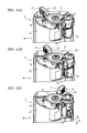
- FIG. 9A is a right side view showing the toner container in a situation, in which the lever is located at a first position, in the printer according to the embodiment of the present disclosure.
- FIG. 9B is a right side view showing the toner container in another situation, in which the lever is located at a second position, in the printer according to the embodiment of the present disclosure.
- FIG. 9C is a right side view showing the toner container in a further situation, in which the lever is located at a third position, in the printer according to the embodiment of the present disclosure.
- FIG. 9A is a right side view showing the toner container in a situation, in which the lever is located at a first position, in the printer according to the embodiment of the present disclosure.
- FIG. 9B is a right side view showing the toner container in another situation, in which the lever is located at a second position, in the printer according to the embodiment of the present disclosure.
- FIG. 9C is a right side view showing the toner container in a further situation, in which the lever
- FIG. 10A is a bottom perspective view showing the toner container in a situation, in which the lever is located at a first position, in the printer according to the embodiment of the present disclosure.
- FIG. 10B is a bottom perspective view showing the toner container in another situation, in which the lever is located at a second position, in the printer according to the embodiment of the present disclosure.
- FIG. 10C is a bottom perspective view showing the toner container in a further situation, in which the lever is located at a third position, in the printer according to the embodiment of the present disclosure.
- FIG. 11A is a schematic diagram showing the toner container in a situation, in which a gripper of the lever engages with a stopper, in the printer according to the embodiment of the present disclosure.
- FIG. 11A is a schematic diagram showing the toner container in a situation, in which a gripper of the lever engages with a stopper, in the printer according to the embodiment of the present disclosure.
- FIG. 11B is a schematic diagram showing the toner container in an ongoing situation, in which the gripper of the lever is shifted from an engaging state with the stopper to a released state, in the printer according to the embodiment of the present disclosure.
- FIG. 11C is a schematic diagram showing the toner container in a situation, in which the engagement of the gripper of the lever with a stopper is released, in the printer according to the embodiment of the present disclosure.
- the gripper 61 of the lever 26 When the printer 1 is taken on market, as shown in FIG. 9A , the gripper 61 of the lever 26 is tilted forward and, as shown in FIG. 10A , the shutter 28 closes the discharge port 35 of the case main body 22 . In addition, as shown in FIG. 11A , the gripper 61 of the lever 26 engages with the stopper 45 , thereby restricting the turn of the lever 26 . A position of the lever 26 at this moment is called as a “first position”.
- the shutter 28 connected with the lever 26 turns, too. Accordingly, as shown in FIG. 10C , the shutter 28 opens the discharge port 35 of the case main body 22 , and then, the inside of the case main body 22 and the inside of the development device 12 are communicated with each other. It is therefore possible to supply the toner from the toner container 5 to the development device 12 .
- the shutter 28 closes the discharge port 35 of the case main body 22 .
- the toner container 5 may be pulled out from the printer main body 2 .
- the toner container 5 by installing the toner container 5 to the printer main body 2 in the situation of the lever 26 located at the first position, it is possible to close the upper cover 6 in a situation, in which the shutter 28 closes the discharge port 35 of the case main body 22 . Accordingly, it is possible to surely prevent the toner from leaking from the toner container 5 during transport and to take the toner container 5 combined with the printer main body 2 on market. Therefore, the specific packaging material for packing the toner container 5 is unnecessary, thereby decreasing a packaging cost.
- the embodiment is configured so that the gripper 61 of the lever 26 gets over the inclined parts 53 of the stopper 45 , when the gripper 61 of the lever 26 shifts from an engagement state with the stopper 45 to a release state. Therefore, it is possible to prevent the lever 26 turned once from the first position to the second position from going back to the first position again.
- the transmission coupling 66 is formed in a triangle shape in a side view and the drive coupling 90 attachably/detachably jointed to the transmission coupling 66 is formed in a triangle shape in a side view corresponding to the transmission coupling 66 .
- the transmission coupling 66 may be formed in a roughly fan shape as shown in FIG. 12B , in a roughly arc shape as shown in FIG. 12C or in a rectangular shape as shown in FIG. 12D .
- the drive coupling 90 may be variously formed in a jointable shape with the corresponding to the transmission coupling 66 .
- the transmission coupling 66 and drive coupling 90 are differently formed according to each destination, it is possible to prevent the toner container 5 for one destination being installed to the printer main body 2 for another destination and to restrict failure caused by mistaken installation of the toner container 5 .
- the configuration of the disclosure was described in case of applying the configuration of the disclosure to the upper cover 6 .
- the configuration of the disclosure may be applied to a front cover, a side cover or another cover.
- lever 26 and shutter 28 may be formed in a body.
- the embodiment was described in a case where ideas of the disclosure are applied to the printer 1 , as a furthermore embodiment, the ideas of the disclosure may be applied to another image forming apparatus except the printer 1 , such as a copying machine, a facsimile or a multifunction machine.
Landscapes
- Physics & Mathematics (AREA)
- General Physics & Mathematics (AREA)
- Dry Development In Electrophotography (AREA)
- Electrophotography Configuration And Component (AREA)
Applications Claiming Priority (2)
| Application Number | Priority Date | Filing Date | Title |
|---|---|---|---|
| JP2012-124853 | 2012-05-31 | ||
| JP2012124853A JP5568597B2 (ja) | 2012-05-31 | 2012-05-31 | 画像形成装置及びトナー容器 |
Publications (2)
| Publication Number | Publication Date |
|---|---|
| US20130322925A1 US20130322925A1 (en) | 2013-12-05 |
| US8995885B2 true US8995885B2 (en) | 2015-03-31 |
Family
ID=48463816
Family Applications (1)
| Application Number | Title | Priority Date | Filing Date |
|---|---|---|---|
| US13/897,182 Active 2033-06-01 US8995885B2 (en) | 2012-05-31 | 2013-05-17 | Image forming apparatus and toner case |
Country Status (4)
| Country | Link |
|---|---|
| US (1) | US8995885B2 (de) |
| EP (1) | EP2669747B1 (de) |
| JP (1) | JP5568597B2 (de) |
| CN (1) | CN103454879B (de) |
Cited By (1)
| Publication number | Priority date | Publication date | Assignee | Title |
|---|---|---|---|---|
| US10859947B2 (en) | 2019-01-22 | 2020-12-08 | Kyocera Document Solutions Inc. | Toner container having operation member for making shutter open or close and image forming apparatus |
Families Citing this family (16)
| Publication number | Priority date | Publication date | Assignee | Title |
|---|---|---|---|---|
| CN104081290B (zh) * | 2012-01-31 | 2018-06-08 | 京瓷办公信息系统株式会社 | 图像形成装置以及调色剂容器 |
| JP5722277B2 (ja) * | 2012-05-31 | 2015-05-20 | 京セラドキュメントソリューションズ株式会社 | 画像形成装置及びトナー容器 |
| JP5953287B2 (ja) * | 2013-11-28 | 2016-07-20 | 京セラドキュメントソリューションズ株式会社 | 画像形成装置 |
| JP6234293B2 (ja) | 2014-03-25 | 2017-11-22 | キヤノン株式会社 | 画像形成装置 |
| JP6173271B2 (ja) * | 2014-07-30 | 2017-08-02 | 京セラドキュメントソリューションズ株式会社 | トナー容器、画像形成装置 |
| JP6304117B2 (ja) * | 2015-04-27 | 2018-04-04 | 京セラドキュメントソリューションズ株式会社 | 現像剤補給装置、およびこれを備えた現像装置、画像形成装置、現像剤補給装置に装着される現像剤収容容器 |
| JP6390564B2 (ja) * | 2015-09-11 | 2018-09-19 | 京セラドキュメントソリューションズ株式会社 | 画像形成装置 |
| JP6686402B2 (ja) | 2015-12-08 | 2020-04-22 | 株式会社リコー | ロックレバー構造、ユニット、画像形成装置 |
| JP6711672B2 (ja) * | 2016-04-05 | 2020-06-17 | キヤノン株式会社 | 画像形成装置 |
| JP6658396B2 (ja) | 2016-08-10 | 2020-03-04 | 京セラドキュメントソリューションズ株式会社 | 画像形成装置 |
| RU2712977C1 (ru) | 2016-09-30 | 2020-02-03 | Кэнон Кабусики Кайся | Картридж с тонером и механизм подачи тонера |
| JP6638640B2 (ja) * | 2016-12-22 | 2020-01-29 | 京セラドキュメントソリューションズ株式会社 | トナー容器及び画像形成装置 |
| JP7069948B2 (ja) * | 2018-03-28 | 2022-05-18 | 京セラドキュメントソリューションズ株式会社 | トナー容器及び画像形成装置 |
| GB201903438D0 (en) * | 2019-03-13 | 2019-04-24 | Ricoh Co Ltd | Device for controlling access to containers for dispensing printing material |
| JP7318425B2 (ja) * | 2019-09-02 | 2023-08-01 | ブラザー工業株式会社 | 画像形成装置 |
| JP7527843B2 (ja) * | 2020-05-22 | 2024-08-05 | キヤノン株式会社 | 画像形成システム |
Citations (4)
| Publication number | Priority date | Publication date | Assignee | Title |
|---|---|---|---|---|
| US5983054A (en) * | 1998-01-20 | 1999-11-09 | Ricoh Company, Ltd. | Method and image forming apparatus for preventing the use of unsuitable process cartridges |
| US20030223782A1 (en) * | 2002-04-25 | 2003-12-04 | Canon Kabushiki Kaisha | Developer supply container |
| JP2009168856A (ja) | 2008-01-10 | 2009-07-30 | Kyocera Mita Corp | トナーコンテナ |
| US20110255906A1 (en) * | 2010-04-16 | 2011-10-20 | Oki Data Corporation | Developer storage body, developing device and image forming apparatus |
Family Cites Families (12)
| Publication number | Priority date | Publication date | Assignee | Title |
|---|---|---|---|---|
| JP3320285B2 (ja) * | 1995-10-26 | 2002-09-03 | キヤノン株式会社 | トナー補給容器 |
| JP3517610B2 (ja) * | 1999-07-28 | 2004-04-12 | 京セラミタ株式会社 | 画像形成ユニットおよび画像形成装置 |
| JP4034072B2 (ja) * | 2002-01-10 | 2008-01-16 | シャープ株式会社 | トナーカートリッジおよびその梱包方法 |
| CN100501603C (zh) * | 2005-05-11 | 2009-06-17 | 兄弟工业株式会社 | 处理盒,盒,图像携带体盒,显影盒,色粉盒,和图像形成设备 |
| JP4701830B2 (ja) * | 2005-05-11 | 2011-06-15 | ブラザー工業株式会社 | プロセスカートリッジ及び画像形成装置 |
| JP2008116479A (ja) * | 2006-10-31 | 2008-05-22 | Kyocera Mita Corp | 画像形成装置 |
| JP5140438B2 (ja) * | 2007-01-24 | 2013-02-06 | 京セラドキュメントソリューションズ株式会社 | トナーコンテナ及び画像形成装置 |
| JP4893341B2 (ja) * | 2007-01-30 | 2012-03-07 | ブラザー工業株式会社 | 現像装置 |
| JP2009080477A (ja) * | 2007-09-05 | 2009-04-16 | Kyocera Mita Corp | トナーカートリッジの着脱構造 |
| JP5255955B2 (ja) * | 2008-08-29 | 2013-08-07 | 京セラドキュメントソリューションズ株式会社 | トナーカートリッジの着脱構造 |
| JP4370540B1 (ja) * | 2009-03-11 | 2009-11-25 | 富士ゼロックス株式会社 | 像形成剤収容容器、画像形成装置、像形成剤収容容器の装着方法、及び像形成剤収容容器の取り外し方法 |
| JP5719795B2 (ja) * | 2012-03-29 | 2015-05-20 | 京セラドキュメントソリューションズ株式会社 | 画像形成装置 |
-
2012
- 2012-05-31 JP JP2012124853A patent/JP5568597B2/ja active Active
-
2013
- 2013-05-17 US US13/897,182 patent/US8995885B2/en active Active
- 2013-05-21 EP EP13168471.4A patent/EP2669747B1/de active Active
- 2013-05-22 CN CN201310193079.XA patent/CN103454879B/zh active Active
Patent Citations (4)
| Publication number | Priority date | Publication date | Assignee | Title |
|---|---|---|---|---|
| US5983054A (en) * | 1998-01-20 | 1999-11-09 | Ricoh Company, Ltd. | Method and image forming apparatus for preventing the use of unsuitable process cartridges |
| US20030223782A1 (en) * | 2002-04-25 | 2003-12-04 | Canon Kabushiki Kaisha | Developer supply container |
| JP2009168856A (ja) | 2008-01-10 | 2009-07-30 | Kyocera Mita Corp | トナーコンテナ |
| US20110255906A1 (en) * | 2010-04-16 | 2011-10-20 | Oki Data Corporation | Developer storage body, developing device and image forming apparatus |
Non-Patent Citations (1)
| Title |
|---|
| Machine translation of Nishimura JP 2009-168856 A, publication date:Jul. 30, 2009. * |
Cited By (1)
| Publication number | Priority date | Publication date | Assignee | Title |
|---|---|---|---|---|
| US10859947B2 (en) | 2019-01-22 | 2020-12-08 | Kyocera Document Solutions Inc. | Toner container having operation member for making shutter open or close and image forming apparatus |
Also Published As
| Publication number | Publication date |
|---|---|
| EP2669747A3 (de) | 2016-09-21 |
| JP5568597B2 (ja) | 2014-08-06 |
| CN103454879B (zh) | 2016-04-27 |
| US20130322925A1 (en) | 2013-12-05 |
| JP2013250428A (ja) | 2013-12-12 |
| EP2669747B1 (de) | 2017-12-27 |
| CN103454879A (zh) | 2013-12-18 |
| EP2669747A2 (de) | 2013-12-04 |
Similar Documents
| Publication | Publication Date | Title |
|---|---|---|
| US8995885B2 (en) | Image forming apparatus and toner case | |
| US9008555B2 (en) | Image forming apparatus including toner case, driving mechanism, and installed part and toner case therefor | |
| US8977170B2 (en) | Image forming apparatus, toner case and drive transmission mechanism | |
| US9002241B2 (en) | Image forming apparatus and toner case | |
| US8958728B2 (en) | Image forming apparatus and toner case | |
| US9042789B2 (en) | Toner case and image forming apparatus | |
| US8995888B2 (en) | Image forming apparatus and development device | |
| US8983343B2 (en) | Image forming apparatus and toner case | |
| US9110404B2 (en) | Image forming apparatus and toner case | |
| JP5622958B2 (ja) | 画像形成装置 | |
| JP2012203101A (ja) | トナー収納容器及び画像形成装置 | |
| JP5722277B2 (ja) | 画像形成装置及びトナー容器 | |
| JP5622960B2 (ja) | 画像形成装置及びトナー容器 | |
| JP5622961B2 (ja) | 画像形成装置及びトナー容器 | |
| JP5663689B2 (ja) | 画像形成装置及びトナー容器 | |
| JP7255163B2 (ja) | 収納容器の取付構造、画像形成ユニット、画像形成装置 | |
| US20160363888A1 (en) | Toner case and image forming apparatus |
Legal Events
| Date | Code | Title | Description |
|---|---|---|---|
| AS | Assignment |
Owner name: KYOCERA DOCUMENT SOLUTIONS INC., JAPAN Free format text: ASSIGNMENT OF ASSIGNORS INTEREST;ASSIGNOR:FUJII, ATSUSHI;REEL/FRAME:030437/0991 Effective date: 20130515 |
|
| STCF | Information on status: patent grant |
Free format text: PATENTED CASE |
|
| MAFP | Maintenance fee payment |
Free format text: PAYMENT OF MAINTENANCE FEE, 4TH YEAR, LARGE ENTITY (ORIGINAL EVENT CODE: M1551); ENTITY STATUS OF PATENT OWNER: LARGE ENTITY Year of fee payment: 4 |
|
| MAFP | Maintenance fee payment |
Free format text: PAYMENT OF MAINTENANCE FEE, 8TH YEAR, LARGE ENTITY (ORIGINAL EVENT CODE: M1552); ENTITY STATUS OF PATENT OWNER: LARGE ENTITY Year of fee payment: 8 |