US8851713B2 - Lens member and optical unit using said lens member - Google Patents
Lens member and optical unit using said lens member Download PDFInfo
- Publication number
- US8851713B2 US8851713B2 US13/241,138 US201113241138A US8851713B2 US 8851713 B2 US8851713 B2 US 8851713B2 US 201113241138 A US201113241138 A US 201113241138A US 8851713 B2 US8851713 B2 US 8851713B2
- Authority
- US
- United States
- Prior art keywords
- annular
- light
- lens
- central axis
- lens member
- Prior art date
- Legal status (The legal status is an assumption and is not a legal conclusion. Google has not performed a legal analysis and makes no representation as to the accuracy of the status listed.)
- Active, expires
Links
Images


Classifications
-
- F—MECHANICAL ENGINEERING; LIGHTING; HEATING; WEAPONS; BLASTING
- F21—LIGHTING
- F21S—NON-PORTABLE LIGHTING DEVICES; SYSTEMS THEREOF; VEHICLE LIGHTING DEVICES SPECIALLY ADAPTED FOR VEHICLE EXTERIORS
- F21S43/00—Signalling devices specially adapted for vehicle exteriors, e.g. brake lamps, direction indicator lights or reversing lights
- F21S43/10—Signalling devices specially adapted for vehicle exteriors, e.g. brake lamps, direction indicator lights or reversing lights characterised by the light source
- F21S43/13—Signalling devices specially adapted for vehicle exteriors, e.g. brake lamps, direction indicator lights or reversing lights characterised by the light source characterised by the type of light source
- F21S43/14—Light emitting diodes [LED]
-
- F—MECHANICAL ENGINEERING; LIGHTING; HEATING; WEAPONS; BLASTING
- F21—LIGHTING
- F21V—FUNCTIONAL FEATURES OR DETAILS OF LIGHTING DEVICES OR SYSTEMS THEREOF; STRUCTURAL COMBINATIONS OF LIGHTING DEVICES WITH OTHER ARTICLES, NOT OTHERWISE PROVIDED FOR
- F21V5/00—Refractors for light sources
- F21V5/04—Refractors for light sources of lens shape
-
- F—MECHANICAL ENGINEERING; LIGHTING; HEATING; WEAPONS; BLASTING
- F21—LIGHTING
- F21S—NON-PORTABLE LIGHTING DEVICES; SYSTEMS THEREOF; VEHICLE LIGHTING DEVICES SPECIALLY ADAPTED FOR VEHICLE EXTERIORS
- F21S43/00—Signalling devices specially adapted for vehicle exteriors, e.g. brake lamps, direction indicator lights or reversing lights
- F21S43/20—Signalling devices specially adapted for vehicle exteriors, e.g. brake lamps, direction indicator lights or reversing lights characterised by refractors, transparent cover plates, light guides or filters
- F21S43/26—Refractors, transparent cover plates, light guides or filters not provided in groups F21S43/235 - F21S43/255
-
- F—MECHANICAL ENGINEERING; LIGHTING; HEATING; WEAPONS; BLASTING
- F21—LIGHTING
- F21S—NON-PORTABLE LIGHTING DEVICES; SYSTEMS THEREOF; VEHICLE LIGHTING DEVICES SPECIALLY ADAPTED FOR VEHICLE EXTERIORS
- F21S43/00—Signalling devices specially adapted for vehicle exteriors, e.g. brake lamps, direction indicator lights or reversing lights
- F21S43/30—Signalling devices specially adapted for vehicle exteriors, e.g. brake lamps, direction indicator lights or reversing lights characterised by reflectors
- F21S43/31—Optical layout thereof
- F21S43/315—Optical layout thereof using total internal reflection
-
- F21S48/215—
-
- F21S48/2212—
-
- F21S48/236—
-
- F—MECHANICAL ENGINEERING; LIGHTING; HEATING; WEAPONS; BLASTING
- F21—LIGHTING
- F21V—FUNCTIONAL FEATURES OR DETAILS OF LIGHTING DEVICES OR SYSTEMS THEREOF; STRUCTURAL COMBINATIONS OF LIGHTING DEVICES WITH OTHER ARTICLES, NOT OTHERWISE PROVIDED FOR
- F21V5/00—Refractors for light sources
- F21V5/04—Refractors for light sources of lens shape
- F21V5/045—Refractors for light sources of lens shape the lens having discontinuous faces, e.g. Fresnel lenses
-
- F—MECHANICAL ENGINEERING; LIGHTING; HEATING; WEAPONS; BLASTING
- F21—LIGHTING
- F21V—FUNCTIONAL FEATURES OR DETAILS OF LIGHTING DEVICES OR SYSTEMS THEREOF; STRUCTURAL COMBINATIONS OF LIGHTING DEVICES WITH OTHER ARTICLES, NOT OTHERWISE PROVIDED FOR
- F21V7/00—Reflectors for light sources
- F21V7/0091—Reflectors for light sources using total internal reflection
-
- G—PHYSICS
- G02—OPTICS
- G02B—OPTICAL ELEMENTS, SYSTEMS OR APPARATUS
- G02B19/00—Condensers, e.g. light collectors or similar non-imaging optics
- G02B19/0004—Condensers, e.g. light collectors or similar non-imaging optics characterised by the optical means employed
- G02B19/0028—Condensers, e.g. light collectors or similar non-imaging optics characterised by the optical means employed refractive and reflective surfaces, e.g. non-imaging catadioptric systems
-
- G—PHYSICS
- G02—OPTICS
- G02B—OPTICAL ELEMENTS, SYSTEMS OR APPARATUS
- G02B19/00—Condensers, e.g. light collectors or similar non-imaging optics
- G02B19/0033—Condensers, e.g. light collectors or similar non-imaging optics characterised by the use
- G02B19/0047—Condensers, e.g. light collectors or similar non-imaging optics characterised by the use for use with a light source
- G02B19/0061—Condensers, e.g. light collectors or similar non-imaging optics characterised by the use for use with a light source the light source comprising a LED
-
- G—PHYSICS
- G02—OPTICS
- G02B—OPTICAL ELEMENTS, SYSTEMS OR APPARATUS
- G02B3/00—Simple or compound lenses
- G02B3/02—Simple or compound lenses with non-spherical faces
- G02B3/08—Simple or compound lenses with non-spherical faces with discontinuous faces, e.g. Fresnel lens
-
- F—MECHANICAL ENGINEERING; LIGHTING; HEATING; WEAPONS; BLASTING
- F21—LIGHTING
- F21K—NON-ELECTRIC LIGHT SOURCES USING LUMINESCENCE; LIGHT SOURCES USING ELECTROCHEMILUMINESCENCE; LIGHT SOURCES USING CHARGES OF COMBUSTIBLE MATERIAL; LIGHT SOURCES USING SEMICONDUCTOR DEVICES AS LIGHT-GENERATING ELEMENTS; LIGHT SOURCES NOT OTHERWISE PROVIDED FOR
- F21K9/00—Light sources using semiconductor devices as light-generating elements, e.g. using light-emitting diodes [LED] or lasers
-
- F—MECHANICAL ENGINEERING; LIGHTING; HEATING; WEAPONS; BLASTING
- F21—LIGHTING
- F21L—LIGHTING DEVICES OR SYSTEMS THEREOF, BEING PORTABLE OR SPECIALLY ADAPTED FOR TRANSPORTATION
- F21L4/00—Electric lighting devices with self-contained electric batteries or cells
-
- F21Y2101/02—
-
- F21Y2105/001—
-
- F—MECHANICAL ENGINEERING; LIGHTING; HEATING; WEAPONS; BLASTING
- F21—LIGHTING
- F21Y—INDEXING SCHEME ASSOCIATED WITH SUBCLASSES F21K, F21L, F21S and F21V, RELATING TO THE FORM OR THE KIND OF THE LIGHT SOURCES OR OF THE COLOUR OF THE LIGHT EMITTED
- F21Y2105/00—Planar light sources
- F21Y2105/10—Planar light sources comprising a two-dimensional array of point-like light-generating elements
-
- F—MECHANICAL ENGINEERING; LIGHTING; HEATING; WEAPONS; BLASTING
- F21—LIGHTING
- F21Y—INDEXING SCHEME ASSOCIATED WITH SUBCLASSES F21K, F21L, F21S and F21V, RELATING TO THE FORM OR THE KIND OF THE LIGHT SOURCES OR OF THE COLOUR OF THE LIGHT EMITTED
- F21Y2115/00—Light-generating elements of semiconductor light sources
- F21Y2115/10—Light-emitting diodes [LED]
Definitions
- the present invention relates to a lens member used in, for example, light-emitting diode (LED) lighting, and the like and an optical unit including the lens member.
- a lens member used in, for example, light-emitting diode (LED) lighting, and the like and an optical unit including the lens member.
- LED optical products such as lighting, projectors, flash, headlights and tail lamps of automobiles and the like, in which an LED is utilized as a light source, or basic optical devices such as a narrow directivity LED, and so on, generally use a lens for focusing or collimating light emitted from the LED.
- a convex refractive lens is usually employed for this kind of lens, adoption of a Fresnel-lens with the aim of height reduction and thinning is also proposed.
- a lens for a lamp fitting which has a lattice-shaped refracting prism portion formed in a central portion of an inner surface near an optical axis, and also has a lattice-shaped reflecting prism portion formed in a peripheral portion of this lattice-shaped refracting prism portion (refer, for example, to JP 57-55002 A).
- an optical device configured from a refractive lens portion having a lens body provided at a central portion of the optical axis and a reflecting body portion, the reflecting body portion allowing light rays to enter from an inner surface portion and totally internally reflecting the light rays at a paraboloid-shaped reflecting surface, thereby converting the light rays into a parallel beam (refer, for example, to JP H05-281402 A).
- a lens member and an optical device which include a Fresnel-lens surface in which a light-incident surface and a light-exit surface of a TIR lens are divided into light-incident surfaces and light-exit surfaces of a plurality of annular prisms whose positions are suitably and concentrically arranged with respect to a central axis of the lens member (see JP2010-262187A, JP2011-141450A and US2010/0284194A1).
- a lens member including a Fresnel-lens surface as proposed above is used for a illumination device, it is often the case that a light-emitting surface of a light source including at least one LED element is smaller than the Fresnel-lens surface that is disposed to face the light-emitting surface of the light source.
- a central axis of the Fresnel-lens surface of the lens member is disposed to be coincident with a center of the light-emitting surface of the light source, there is a space in a direction perpendicular to the central axis, around the light source.
- parts such as resistances, condensers, connecters and so on for a power circuit may be mounted in the space around the light source.
- the parts adjacent to the light source may interfere with light emitted from the light source and entering the Fresnel-lens surface. Accordingly, there is a possibility that the optical member cannot exert its optical characteristics when parts are arranged in a space around the light source.
- An object of the present invention is to provide a lens member and an optical unit in consideration of above mentioned.
- a lens member includes a central axis, a light-incident side including a Fresnel-lens surface provided with a plurality of annular prisms that are concentrically arranged with respect to the central axis, and a light-exit surface opposite to the light-incident side.
- the annular lens portion is concentrically arranged with respect to the central axis in a part of the Fresnel-lens surface of the lens member.
- the annular lens portion may be positioned at an outer peripheral portion of the Fresnel-lens surface.
- Some of the plurality of annular prisms may be positioned outside of the annular outer surface of the annular lens portion.
- the Fresnel-lens surface further includes an annular lens portion that is concentrically arranged with respect to the central axis and that is extended to be longer and wider than the plurality of annular prisms.
- the annular lens portion include an annular inner surface and an annular outer surface that is positioned outside the annular inner surface.
- the annular inner surface and the annular outer surface may be in contact with each other to form a common lower edge and make a shape of an acute angle at the common lower edge.
- the annular inner surface and the annular outer surface may be inclined surfaces each having an angle with respect to the central axis.
- an annular lens portion in another embodiment, includes an annular inner surface, an annular outer surface, and an annular inclined surface connecting a lower end of the annular inner surface and a lower end of the annular outer surface of the annular lens portion.
- the annular inner surface and the annular outer surface of the annular lens may be extended parallel to the central axis and extended below the light-incident side.
- the annular inner surface may be extended to be longer than the annular outer surface.
- the annular inclined surface inclining upward from the lower end of the annular inner surface to the lower end of the annular outer surface.
- an annular lens portion includes an annular inner surface and an annular outer surface extending parallel to the central axis, respectively.
- the annular inner surface introduces light emitted from the light source therein.
- the annular outer surface refracts and reflects a part of the light entered the annular inner surface to direct toward annular prisms positioned outside the annular lens portion.
- annular lens portion is provided on an outer peripheral edge of a Fresnel-lens surface.
- the annular lens portion includes an annular inner surface and an annular outer surface positioned outside the annular inner surface.
- the annular outer surface may be a shape reflecting light entered the annular inner surface toward a light-exit surface.
- a light-exit surface of a lens member has a planar surface.
- a plurality of convex portions is provided on the light-exit surface at a position above an annular lens portion.
- a lens member according to the present invention includes a flat shape as a whole, and includes a concave-shaped surface provided on a light-incident side on a central axis, a Fresnel-lens surface may be provided on the concave-shaped surface.
- a raised surface having the largest thickness is provided on a central axis in the concave-shaped surface, and a Fresnel-lens surface may be provided on a continuous surface of the concave-shaped surface and the central raised surface. Even in such a case, the annular lens portion extends long to a light-incident surface more than the raised surface having an increased thickness on the central axis.
- An optical unit includes the lens member as mentioned above, a light source including a light-exit surface having a smaller area than that of a Fresnel-lens surface of the lens member, and at least one part positioned outside the light source in a direction perpendicular to a central axis at a lower side of a light-incident side of the lens member.
- the light source and the part are mounted on a substrate positioned below the light-incident side of the lens member.
- the part is positioned outside an annular lens portion of the lens member in the direction perpendicular to the central axis.
- the part is positioned outside the annular lens portion in the direction perpendicular to the central axis and positioned below an outer peripheral portion of the Fresnel-lens surface of the lens member.
- a frame to support an outer peripheral portion of the lens member so that a center of the light-exit surface of the light source is positioned on the central axis of the lens member may be provided.
- FIG. 1 is a plan view of a lens member according to a first embodiment of the present invention.
- FIG. 2 is a cross-sectional view taken along the line II-II of the lens member shown in FIG. 1 .
- FIG. 3 is an explanatory diagram showing a principle of a TIR lens.
- FIG. 4 is an explanatory diagram showing a principle of the lens member including a Fresnel-lens surface.
- FIG. 5 is a sectional view showing one example of the lens member in which an annular lens portion is not provided and explaining a positional relationship between a light source and a substrate.
- FIG. 6 is a sectional view of an optical unit in which the lens member according to the first embodiment is assembled.
- FIG. 7 is a perspective view of the optical unit shown in FIG. 6 .
- FIG. 8 is a cross-sectional view of a lens member in a second embodiment of the present invention.
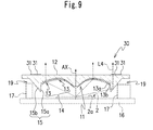
- FIG. 9 is a cross-sectional view of a lens member in a third embodiment of the present invention.
- FIGS. 1 and 2 illustrate a lens member 10 according to a first embodiment of the present invention.
- Reference sign AX shows a central axis that is an imaginary line passing through a center of the lens member 10 .
- the lens member 10 in the first embodiment includes the central axis AX, a light-incident side 11 including a Fresnel-lens surface 14 provided with a plurality of annular prisms 13 that are concentrically arranged with respect to the central axis AX.
- the Fresnel-lens surface further includes an annular lens portion 15 that is concentrically arranged with respect to the central axis AX, and the annular lens portion 15 is extended to be wider in a direction perpendicular to the central axis AX than the plurality of annular prisms and is extended to be longer in a direction parallel to the central axis below the light-incident side 11 than the plurality of annular prisms 13 .
- the annular lens portion 15 includes an annular inner surface 15 a and an annular outer surface 15 b positioned in a direction perpendicular to the central axis AX outside the annular inner surface 15 a .
- the annular inner surface 15 a and the annular outer surface 15 b are in contact with each other to form a common lower edge and make an acute angle at the common lower edge by the annular inner surface 15 a and the annular outer surface 15 b .
- the annular inner surface 15 a and the annular outer surface 15 b are inclined surfaces having respective angles with respect to the central axis AX.
- Each of the plurality of annular prisms 13 of the Fresnel-lens surface includes an annular inner surface 13 a and an annular outer surface 13 b positioned in a direction perpendicular to the central axis AX outside the annular inner surface 13 a .
- light received through the annular inner surface 13 a is totally reflected on the annular outer surface 13 b toward the light-exit surface 12 .
- the lens member 10 includes a Fresnel-lens surface 14 , its configuration is conceptually described with reference to FIGS. 3 and 4 .
- the TIR lens 1 is generally a bulky lens and includes a light-incident surface 3 and a light-reflection surface 4 positioned in a direction perpendicular to a central axis AX outside the light-incident surface 3 .
- a lens member including a Fresnel-lens surface is proposed (see JP2010-262187A, JP2011-141450A and US2010/0284194A1).
- the light-incident surface 3 is divided into a plurality of divided light-incident surfaces 3 a to 3 c and the light-reflection surface 4 is divided into a plurality of divided light-reflection surfaces 4 a to 4 c , and combinations of divided light-incident surfaces and divided light-reflection surfaces are repositioned as a plurality of annular prisms 14 . As shown in FIG.
- the most intensified light which passes through the light-incident surface at 3 a and is reflected on the light-reflection surface at 4 a to be directed toward a light-exit surface is L 1
- the less intensified light L 2 than the most intensified light L 1 passes through the light-incident surface at 3 b and is reflected on the light-reflection surface at 4 b to be directed toward the light-exit surface
- the least intensified light L 3 of all passes through the light-incident surface at 3 c and is reflected on the light-reflection surface at 4 c to be directed toward the light-exit surface.
- the lens member 11 has a plate shape as a whole and includes a Fresnel-lens surface 11 at a light-incident side.
- the Fresnel-lens surface 11 is provided with a plurality of annular prisms 14 that are concentrically arranged with respect to the central axis AX of the lens member 10 A.
- Each of the plurality of annular prisms 14 includes an annular inner surface 13 a and an annular outer surface 13 b that is positioned in a direction perpendicular to the central axis AX outside the annular inner surface 13 a .
- the annular prisms 14 of the lens member 10 A are repositioned as annular prisms 13 C, 13 B, 13 B, and 13 A from the light-incident surface 3 and the light-reflection surface 4 of the bulky lens 1 to exit a desired light.
- the number of the annular prisms in the drawings is exaggerated for explanation and not limited thereto.
- the lens member 10 of the present invention may have a Fresnel-lens surface mentioned above.
- the lens member 10 according to the first embodiment has a plate-shape as a whole.
- the plurality of annular prisms 13 including a plurality of annular inner surfaces 13 a and annular outer surfaces 13 b of the Fresnel-lens surface 14 may have different light-refracting angles with respect to each other.
- the Fresnel-lens surface 11 of the lens member 10 is disposed to face a light-emitting surface 2 a of a light source 2 with the central axis AX and the center of the light-emitting surface 2 a of the light source 2 being coincident with each other.
- the light source 2 may include at least one LED element.
- the lens member 10 A including the Fresnel-lens surface 11 may be integrally formed by a light-transmitting resin such as acryl resin.
- a light-transmitting resin such as acryl resin.
- each of the annular prisms 13 may be formed by a planar surface or convex-shaped quadratic surface, but is preferably formed by a planar surface in consideration of workability.
- the annular outer surface 13 b may be formed by a planar surface or aspheric surface such as a paraboloidal surface, hyperboloid surface, elliptical surface or the like, but is preferably formed by the planar surface in consideration of workability of minute annular prisms.
- the light-exit surface 12 opposite to the Fresnel-lens surface 14 includes a flat surface.
- the annular lens portion 15 of the lens member 10 is provided on an outer peripheral edge portion of the Fresnel-lens surface 14 that includes the plurality of annular prisms 13 .
- the annular lens portion 15 is concentrically arranged with respect to the central axis AX. In other words, the annular lens portion 15 is formed in an annular shape about the central axis AX.
- the annular lens portion 15 includes an annular inner surface 15 a and an annular outer surface 15 b positioned in a direction perpendicular to the central axis AX outside the annular inner surface 15 a , a lower edge of the annular inner surface 15 a and a lower edge of the annular outer surface 15 b are in contact with each other to form a common lower edge and make an acute angle at the common lower edge.
- the annular lens portion 15 is extended to be longer and wider than the plurality of annular prisms 13 .
- the annular lens portion 15 is disposed wider in a direction perpendicular to the central axis AX and longer in a direction of the central axis AX than the plurality of annular prisms.
- the annular lens portion 15 is concentrically arranged with respect to the central axis AX, and is concentrically arranged outside the plurality of annular prisms 13 , and therefore, it is possible to direct light that is emitted from the light source 2 with a wider incident angle tilting wider in a direction perpendicular to the central axis AX than light that is emitted from the light source 2 with an acute incident angle, toward the light-exit surface.
- the annular lens portion 15 is provided in a part of the Fresnel-lens surface, but the annular lens portion is not Fresnel-ized.
- the divided light-incident surface 3 c shorter than other divided light-incident surfaces 3 a and 3 b and the divided light reflection surface 4 c shorter than other divided light-reflection surfaces 4 a and 4 b are not Fresnel-ized and disposed at an outer peripheral portion of the Fresnel-lens surface 14 as the annular lens portion 15 .
- the thickness of the lens member 10 is kept thin enough, even if the shorter divided light-incident surface 3 c and the shorter light reflection surface are not Fresnel-ized or not divided into some annular prisms.
- the annular lens portion 15 includes the annular inner surface 15 a that receives light emitted from the light source 2 with a wide angle with respect to the central axis AX and the annular outer surface 15 b that totally reflect the received light received through the annular inner surface 15 a toward the light-exit surface 12 . That is, the annular lens portion 15 has approximately a V-shape in section and the annular lens portion 15 is concentrically arranged with respect to the central axis AX of the lens member.
- the annular inner surface 15 a and the annular outer surface 15 b of the annular lens portion 15 are in contact with each other to form a common lower edge and make an acute angle at the common lower edge.
- An annular flat surface or aspheric chamfer may be provided at the common lower edge of the annular inner surface 15 a and the annular outer surface 15 b .
- the annular lens portion 15 is disposed instead of some of the annular prisms 13 which are supposed to be provided on the outer peripheral portion of the Fresnel-lens surface 14 (conceptually, corresponding to a part or entirety of the annular prism 13 C as shown in FIG. 4 ) and the annular lens portion 15 has a projecting portion which is extended below the light-incident side 11 longer than the plurality of annular prisms 13 .
- the annular lens portion 15 extends to be wider and longer below the light-incident side 11 than the plurality of annular prisms 13 , the annular lens portion can receive light emitted from the light source 2 with a wide angle with respect to the central axis AX, of light emitted from a light-emitting surface 2 a of the light source 2 that is disposed to face the Fresnel-lens surface 14 of the lens member 10 and reflects upward and/or refracts the received light.
- the annular lens portion 15 configured to change a light path of light emitted from the light source 2 with a wide angle is disposed in a direction perpendicular to the central axis AX outside the light-emitting surface 2 a of the light source 2 .
- the lens member 10 and the light source 2 are disposed to form a unit, since the light-emitting surface 2 a of the light source 2 has an area smaller than an area of the Fresnel-lens surface 14 , a space around the light source 2 under the periphery of the lens member can be used.
- a peripheral lens portion provided, light emitted from the light source with an angle in a direction perpendicular to the central axis AX can be received by the Fresnel-lens surface and the space around the light source 2 can be used to dispose separate parts or members.
- the annular inner surface 15 a and the annular outer surface 15 b are formed by a planar surface or aspheric surface such as a paraboloidal surface, hyperboloid surface, elliptical surface or the like, but are preferably formed by the planar surface in consideration of workability.
- the light source 2 may include a plurality of LED elements.
- a light source including a plurality of LED elements arranged in a grid-like shape may be adopted and the light source 2 may be formed by only one LED element.
- the present invention it is possible to dispose electronic parts in an outer peripheral space around the light source 2 and to maintain an optical characteristic of the lens member 10 , when the Fresnel-lens surface 14 of the lens member 10 which is thinned as exemplified is used to face the light-emitting surface 2 a of the light source 2 .
- the annular lens portion 15 provided on the lens member 10 it is possible to receive light at a wide angle from the light source 2 and enhance significantly use efficiency of the light, and align a distribution of the light emitted from the light-emitting surface 2 a of the light source 2 .
- the light-emitting surface 2 a of the light source 2 disposed to face the Fresnel-lens surface 14 of the lens member 10 is lesser than the Fresnel-lens surface 14 of the lens member 10 in area.
- Light emitted from the light source 2 is light on the optical axis, that is to say, most intensified light is emitted to a direction along the central axis AX of the lens member 10 is strongest. However, light from the light source 2 is entered the Fresnel-lens surface 14 with a light-incident angle from a narrow angle to a wide angle with respect to the central axis AX as going away from the central axis AX to an outer periphery end of the Fresnel-lens surface 14 .
- the light-incident side 11 includes a Fresnel-lens surface provided with a plurality of annular prisms concentrically arranged with respect to the central axis AX on a continuous surface continuously formed by a concave-shaped surface and a raised surface that is disposed on the central axis and in the center of the concave-shaped surface, a light-exit surface opposite to the light-incident side 11 and the Fresnel-lens surface further includes an annular lens portion that is concentrically arranged with respect to the central axis and that is extended longer and wider than the plurality of annual prisms.
- the annular lens portion is extended below the light-incident side longer than the raised surface at the central axis AX. More specifically, the Fresnel-lens surface 14 has a structure in which a central portion and an outer peripheral edge portion are projected more beneath than the light-incident side 11 and the light-incident side 11 has a concaved shape between the central portion and the outer peripheral edge portion.
- a plurality of concentric annular prisms 13 about the central axis AX are continuously formed on the continuous surface 13 c comprising the concave-shaped surface and the central raised surface from a periphery of the central axis AX toward the direction perpendicular to the central axis AX.
- the lens member has a structure easy to pick up light emitted from the light source 2 with a wide angle at the annular prisms 13 provided on the outer peripheral edge projecting below the light-incident side 11 , while the light emitted from the light source 2 with a wide angle can efficiently be picked up by providing further the annular lens portion 15 on a part of the Fresnel-lens surface 14 extending to be long and wider than the plurality of annular prisms provided on the Fresnel-lens surface 14 .
- the light source including the light-exit surface having an area smaller than that of the Fresnel-lens surface of the lens surface, and the light-entrance and the light-emission at the annular lens portion 15 provided on an outer peripheral side of the light source in the direction perpendicular to the central axis are explained.
- the annular lens portion 15 according to the present invention is not provided on the Fresnel-lens surface 14 .
- an outer peripheral portion of the Fresnel-lens surface 14 corresponds to a peripheral edge portion of a concave-shaped surface formed on the light-incident side 11 .
- the outer peripheral portion is disposed to approach a substrate 16 on which the light source 2 is mounted, to pick up light emitted from the light source 2 at a wide angle.
- the annular lens portion 15 is provided on the outer peripheral portion of the annular prisms 13 , and parts 17 for a power circuit are mounted in an empty space 19 of an outside area of the annular lens portion 15 .
- the optical unit 120 includes the lens member 10 having the Fresnel-lens surface 14 and the annular lens portion 15 , as mentioned above, a light source 2 including the light-emitting surface 2 a having an area smaller than that of the Fresnel-lens surface 14 of the lens member 10 , a substrate 16 disposed to face the light-incident side 11 of the lens member 10 , the parts 17 for the power circuit, mounted on the substrate 16 below the Fresnel-lens surface 14 at a position outside the annular lens portion 15 , and a casing 121 to house the aforementioned components.
- the light source 2 is mounted on the substrate 16 so that a center of the light-emitting surface 2 a of the light source 2 is positioned on the central axis AX.
- the casing 121 includes a hemispherical portion 122 and an upper surface portion provided to close the hemispherical portion 122 .
- the lens member 10 including the Fresnel-lens surface 14 disposed to face the light-exit surface of the light source 2 is disposed on a central portion of the upper surface portion.
- a frame 123 supporting an outer peripheral portion of the lens member 10 is provided so that a center of the light-emitting surface 2 a of the light source 2 is aligned with the central axis AX of the lens member 10 .
- the frame 123 has approximately a cylindrical shape, whose central axis aligns with a central axis of the hemispherical portion 122 , and disposed on the upper surface portion of the hemispherical portion 122 in a state where the lens member 10 is disposed to face the light source 2 .
- the annular lens portion 15 is provided on an outer peripheral portion of the Fresnel-lens surface 14 comprising the plurality of annular prisms 13 concentrically arranged with respect to the central axis AX, a light path of light emitted from the light source 2 at a narrow angle is changed by the annular prisms 13 arranged inside the annular lens portion 15 in a direction perpendicular to the central axis AX to be directed to the light-exit surface 12 , and a light path of light emitted from the light source 2 at a wide angle is changed by the annular lens portion 15 to be directed to the light-exit surface 12 .
- the optical unit 120 includes the lens portion 10 , the substrate 16 disposed below the light-incident side 11 of the lens member 10 , the light source 2 disposed on the substrate 16 , the frame 123 supporting the outer peripheral portion of the lens portion 10 so that the center of the light-emitting surface 2 a of the light source 2 aligns with the central axis AX of the lens member 10 , at least one part 17 mounted on the substrate 16 and disposed inside the frame 123 and below the light-incident side 11 of the lens member 10 .
- the light-emitting surface 2 a of the light source 2 is lesser than the Fresnel-lens surface 14 of the lens member 10 in size and disposed inside the annular inner surface 15 a of the annular lens portion 15 , and the at least one part 17 is disposed outside the annular lens portion 15 .
- the space 19 to dispose, for example, the part 17 for power circuit as one part is secured between the lens member 10 and the substrate 16 .
- the optical unit 120 can be thinned and miniaturized as a whole and has a high use efficiency of the light emitted from the light source 2 , and is suitably used for optical products and so on such as illuminators, projectors, flashes, head lamps or tail lamps for a vehicle.
- optical products and so on such as illuminators, projectors, flashes, head lamps or tail lamps for a vehicle.
- the optical unit 120 even if the light source 2 is formed by arranging a plurality of LED elements, color unevenness of the LED elements can be prevented.
- FIG. 8 illustrates a lens member according to a second embodiment of the present invention.
- the lens member 20 according to the second embodiment only parts different from the first embodiment with respect to the lens member 20 are described, identical reference numbers are attached to parts similar to that in the first embodiment, a detailed description thereof is omitte.
- the annular lens portion 15 is provided on the outer peripheral portion of the Fresnel-lens surface 14 .
- there are some of the plurality of annular prisms are positioned outside of the annular outer surface of the annular lens portion.
- an annular lens portion 25 is provided on an intermediate portion of the Fresnel-lens surface 14 between the central axis AX and an outer peripheral portion of the Fresnel-lens surface 14 , as shown in FIG. 8 . That is, in the lens member 20 in the second embodiment, annular prisms 13 of the Fresnel-lens surface 14 are further provided outside the annular lens portion 15 .
- the annular lens portion 25 includes an annular outer surface 25 c to transmit a part of light entered an annular inner surface 25 a to direct to the annular prisms 13 that are positioned outside the annular lens portion 25 .
- the annular outer surface 25 c has a surface parallel with the annular inner surface 25 a in sectional shape.
- a lower end of the annular inner surface 25 a and a lower end of the annular outer surface 25 c extend parallel with the central axis AX below the light-incident side 11 , and the annular inner surface 25 a extends long more than the annular outer surface 25 c .
- An annular inclined surface 25 b is disposed between the annular inner surface 25 a and the annular outer surface 25 c , and connects the lower end of the annular inner surface 25 a and the lower end of the annular outer surface 25 c to extend from the annular inner surface 25 a to the annular outer surface 25 c obliquely and upwardly.
- the annular inclined surface 25 b is a reflection surface reflecting light which is entered the annular inner surface 25 a and directed to the inclined surface 25 b.
- At least one part 17 for a power circuit is mounted on the substrate 16 below the outer peripheral portion of the Fresnel-lens surface 14 and at an outer peripheral portion of the light source 2 mounted on the substrate 16 in a direction perpendicular to the central axis AX, similarly to the first embodiment. More specifically, the part 17 for a power circuit is disposed on the substrate 16 to face the annular prisms 13 provided outside the annular lens portion 25 .
- the annular lens portion 25 is provided annularly about the central axis AX at an intermediate portion of the Fresnel-lens surface 14 between the central axis AX and an outer end portion of the Fresnel-lens surface 14 , it is possible to provide a part of the plurality of annular prisms 13 even on an outer side of the annular lens portion 25 .
- the annular prisms 13 provided outside the annular lens portion 25 can be set at a high position.
- the annular lens portion 25 of the lens member 20 includes the annular outer surface 25 c that transmits a part of the light entered the annular inner surface 25 a toward the annular prisms 13 that are positioned outside the annular lens portion 25 in a direction perpendicular to the central axis AX
- the annular lens portion 24 can be provided inside the outer end portion of the Fresnel-lens surface 14 and a further large space 29 to house the part 17 for a power circuit can be secured outside the annular lens portion 25 in a direction perpendicular to the central axis AX.
- the light path of the light transmitting the annular outer surface 25 c of the annular lens portion 25 is changed by the annular prisms 13 positioned outside the annular lens portion 25 , and the light that the light path is changed is emitted from the light-exit surface 12 , it is possible to exert optical characteristics of the lens member even if a space around the light source is used.
- FIG. 9 illustrates a lens member according to a third embodiment of the present invention.
- a plurality of convex portions 31 is provided on a part of the light-exit surface 12 .
- the convex portions 31 are provided on the light-exit surface 12 at an above position of the annular lens portion 15 provided on the light-incident side 11 of the lens member 30 .
- the convex portions correspond to an outer peripheral portion of the light-exit surface 12 .
- the convex portions 31 have a function to control at least one of diffusivity and directivity of the light emitted from the light-exit surface 12 .
- convex portions for example, a plurality of protrusions each having an elliptical shape in section may be annularly arranged on the light-exit surface 12 to diffuse emitted light.
- the convex portions are preferably formed in aspheric convex or concave portions. Note that as other convex or concave shapes, for example, square pyramid-like shape convex or concave portions may be used.
- the convex portions 31 having a function to control at least one of diffusivity and directivity of light are formed on the light-exit surface 12 , it is easy to emit light that a light path is changed by the annular lens portion 15 to be directed toward the light-exit surface 12 by the convex portions 31 or concave portions provided on the light-exit surface 12 for refraction or diffusion of light with a predetermined diffusivity or directivity.
- a brightness balance between light that a light path is changed to be directed toward the light-exit surface 12 by the annular lens portion 15 and light that a light path is changed by the annular prisms 13 of the Fresnel-lens surface 14 , at the light-exit surface 12 can be adjusted, and a distribution of emitted light can be adjusted.
- convex or concave portions may be provided on the light-exit surface 12 of the lens member 30 at a position of the light-exit surface facing the plurality of annular prisms 13 provided on the light-incident side 11 of the lens member 30 . In this case, it is possible to reduce color evenness more than the lens member 10 in the first embodiment.
- the convex portions 31 or concave portions may be provided inside the annular lens portion 15 on the light-exit surface 12 of the lens member 30 .
- a more great deal of light can be diffused on a periphery of the central axis AX where color evenness of the light emitted from the light source 2 is easy to be produced and the color evenness can be obtained effectively, by adjusting a degree of diffusivity of light passing through the convex portions 31 or concave portions to be higher than that in a portion of the light-exit surface where the convex portions or concave portions are not provided.
- an optical sheet such as a diffusion sheet to diffuse light uniformly, or anisotropic diffusion sheet or prism sheet to diffuse or refract light in a particular direction may be provided optionally on the light-exit surface.
- a optical sheet disposed on the light-exit surface of the lens member, convex or concave portions provided on the light-exit surface directly may be omitted.
- a material having a smaller refraction index difference than that of a material constituting the lens member is selected.
- the provision of the optical sheet to control at least one of the diffusivity and the directivity of the light transmitting the light-exit surface of the lens member makes it possible to emit easily light that the light path is changed to be directed toward the light-exit surface by the plurality of annular prisms or the annular lens portion of the Fresnel-lens surface, by the refraction and diffusion of the optical sheet provided on the light-exit surface with a desired diffusivity or directivity.
Landscapes
- Physics & Mathematics (AREA)
- Engineering & Computer Science (AREA)
- General Engineering & Computer Science (AREA)
- Optics & Photonics (AREA)
- General Physics & Mathematics (AREA)
- Microelectronics & Electronic Packaging (AREA)
- Lenses (AREA)
- Non-Portable Lighting Devices Or Systems Thereof (AREA)
- Planar Illumination Modules (AREA)
- Led Device Packages (AREA)
Applications Claiming Priority (2)
| Application Number | Priority Date | Filing Date | Title |
|---|---|---|---|
| JP2010220089A JP5649047B2 (ja) | 2010-09-29 | 2010-09-29 | レンズ部材及び光学ユニット |
| JP2010-220089 | 2010-09-29 |
Publications (2)
| Publication Number | Publication Date |
|---|---|
| US20120075870A1 US20120075870A1 (en) | 2012-03-29 |
| US8851713B2 true US8851713B2 (en) | 2014-10-07 |
Family
ID=45870495
Family Applications (1)
| Application Number | Title | Priority Date | Filing Date |
|---|---|---|---|
| US13/241,138 Active 2032-06-14 US8851713B2 (en) | 2010-09-29 | 2011-09-22 | Lens member and optical unit using said lens member |
Country Status (4)
| Country | Link |
|---|---|
| US (1) | US8851713B2 (ja) |
| JP (1) | JP5649047B2 (ja) |
| CN (1) | CN102563524B (ja) |
| DE (1) | DE102011083586B4 (ja) |
Cited By (3)
| Publication number | Priority date | Publication date | Assignee | Title |
|---|---|---|---|---|
| US20150109137A1 (en) * | 2013-10-23 | 2015-04-23 | Honeywell International Inc. | Multiple LED Omni-Directional Visual Alarm Device |
| US20170082269A1 (en) * | 2013-03-15 | 2017-03-23 | Cree, Inc. | Optical Components for Luminaire |
| CN107810438A (zh) * | 2015-03-23 | 2018-03-16 | 伊古齐尼照明有限公司 | 包括多个组成透镜并且设置有用于消除被传输的光通量中不期望的光效果的装置的tir透镜 |
Families Citing this family (36)
| Publication number | Priority date | Publication date | Assignee | Title |
|---|---|---|---|---|
| JP5807165B2 (ja) * | 2011-01-20 | 2015-11-10 | パナソニックIpマネジメント株式会社 | 照明器具 |
| US9121554B2 (en) * | 2012-03-16 | 2015-09-01 | Rohm Co., Ltd. | LED lamp and lens unit therefor |
| US9109777B2 (en) | 2012-04-16 | 2015-08-18 | Phoseon Technology, Inc. | Linear fresnel optic for reducing angular spread of light from LED array |
| BR112014026316A8 (pt) * | 2012-04-26 | 2021-05-11 | Koninklijke Philips Nv | disposição de iluminação; elemento de iluminação; elemento de redirecionamento da luz; unidade de iluminação automotiva; disposição de iluminação da tela; e disposição de iluminação de retromontagem |
| US9890926B2 (en) | 2012-08-02 | 2018-02-13 | Fraen Corporation | Low profile multi-lens TIR |
| US9046242B2 (en) | 2012-08-10 | 2015-06-02 | Groupe Ledel Inc. | Light dispersion device |
| CN102818161B (zh) * | 2012-09-04 | 2015-12-02 | 上海九高节能技术有限公司 | 一种led灯具 |
| KR101360568B1 (ko) * | 2012-09-14 | 2014-02-11 | 엘지이노텍 주식회사 | 광학 부재 및 이를 포함하는 표시 장치 |
| JP2014157706A (ja) * | 2013-02-15 | 2014-08-28 | Toshiba Lighting & Technology Corp | 照明装置、ランプおよび照明器具 |
| MX2015015657A (es) | 2013-05-14 | 2016-07-20 | Ledil Oy | Guia de luz para modificar un patron de distribucion de la luz. |
| EP3004728A1 (en) * | 2013-06-07 | 2016-04-13 | Koninklijke Philips N.V. | Lens and lighting device |
| US10302275B2 (en) * | 2013-06-19 | 2019-05-28 | Bright View Technologies Corporation | Microstructure-based diffusers for creating batwing lighting patterns |
| KR101362186B1 (ko) | 2013-08-07 | 2014-02-12 | 플럭스라이트(주) | 전반사수단이 구비된 엘이디 가로등의 광확산렌즈 |
| WO2015030169A1 (ja) * | 2013-08-29 | 2015-03-05 | 株式会社エンプラス | 光束制御部材、発光装置および照明装置 |
| TW201516468A (zh) * | 2013-10-25 | 2015-05-01 | Hon Hai Prec Ind Co Ltd | 透鏡組合及使用該透鏡組合的光源裝置 |
| JP6291267B2 (ja) * | 2014-01-29 | 2018-03-14 | 株式会社エンプラス | 光束制御部材、発光装置および照明装置 |
| JP2015170423A (ja) * | 2014-03-05 | 2015-09-28 | 株式会社小糸製作所 | 車両用灯具 |
| TWI512337B (zh) * | 2014-03-24 | 2015-12-11 | Univ Nat Chiao Tung | 照明單元以及體內照明系統 |
| JP6425415B2 (ja) * | 2014-05-02 | 2018-11-21 | 株式会社エンプラス | 光束制御部材、発光装置および照明装置 |
| AT515745A1 (de) * | 2014-05-05 | 2015-11-15 | Alicona Imaging Gmbh | Beleuchtungseinrichtung |
| TW201544852A (zh) * | 2014-05-22 | 2015-12-01 | Beautylight Optronics Co Ltd | 光學膜片 |
| US10935211B2 (en) * | 2014-05-30 | 2021-03-02 | Ideal Industries Lighting Llc | LED luminaire with a smooth outer dome and a cavity with a ridged inner surface |
| JP6390194B2 (ja) * | 2014-06-18 | 2018-09-19 | オムロン株式会社 | 光学素子及び面光源装置 |
| DE102015107443B4 (de) | 2015-05-12 | 2022-01-13 | OSRAM Opto Semiconductors Gesellschaft mit beschränkter Haftung | Linse und optoelektronische Leuchtvorrichtung |
| US10247392B2 (en) * | 2015-06-30 | 2019-04-02 | Chun Kuang Optics Corp. | Luminous system |
| US10995915B2 (en) * | 2015-09-02 | 2021-05-04 | Lumileds Llc | LED module and lighting module |
| CN108604023B (zh) | 2016-02-01 | 2022-04-15 | E-视觉智能光学公司 | 棱镜增强的透镜和使用棱镜增强的透镜的方法 |
| CN107179567A (zh) * | 2016-03-11 | 2017-09-19 | 武汉拉法叶科技有限责任公司 | 车用雨量传感器及其光透镜 |
| JP6758874B2 (ja) * | 2016-03-29 | 2020-09-23 | 本田技研工業株式会社 | 灯火装置 |
| US10585308B2 (en) * | 2016-09-12 | 2020-03-10 | Citizen Watch Co., Ltd. | Light-emitting device |
| DE102017125245A1 (de) * | 2017-10-27 | 2019-05-02 | Siteco Beleuchtungstechnik Gmbh | Abdeckung für ein Leuchtmodul, Leuchtmodul und Leuchte |
| DE102018123789A1 (de) * | 2018-09-26 | 2020-03-26 | Carl Zeiss Jena Gmbh | Leuchteinrichtung für ein Fahrzeug |
| CN110161750B (zh) * | 2019-05-22 | 2022-06-03 | 京东方科技集团股份有限公司 | 透镜结构、光源结构、背光模组和显示装置 |
| CN211043831U (zh) * | 2019-12-19 | 2020-07-17 | 欧普照明股份有限公司 | 一种光学扩束镜和灯具 |
| CZ2020393A3 (cs) * | 2020-07-03 | 2022-01-12 | Varroc Lighting Systems, s.r.o. | Světelný modul, zejména pro osvětlovací zařízení vozidla, a osvětlovací zařízení vozidla |
| WO2023238667A1 (ja) * | 2022-06-09 | 2023-12-14 | 株式会社小糸製作所 | 車両用灯具 |
Citations (16)
| Publication number | Priority date | Publication date | Assignee | Title |
|---|---|---|---|---|
| JPS5755002A (en) | 1980-09-18 | 1982-04-01 | Ichikoh Industries Ltd | Lens for lamp |
| JPS5814405A (ja) | 1981-07-20 | 1983-01-27 | 市光工業株式会社 | 車輛用灯具 |
| JPS59119340A (ja) | 1982-12-27 | 1984-07-10 | Mitsubishi Rayon Co Ltd | フレネルレンズ |
| JPH03116508U (ja) | 1990-03-12 | 1991-12-03 | ||
| WO1993021484A1 (en) | 1992-04-16 | 1993-10-28 | Tir Technologies, Inc. | Faceted totally internally reflecting lens with curved faces |
| JPH05281402A (ja) | 1992-03-31 | 1993-10-29 | Sunx Ltd | 光学装置 |
| JP2002043629A (ja) | 2000-07-24 | 2002-02-08 | Yamakawa Akira | Led投光装置とこれに用いるレンズ体。 |
| CN1343289A (zh) | 2000-01-07 | 2002-04-03 | 皇家菲利浦电子有限公司 | 照明设备 |
| JP2003287792A (ja) | 2002-03-28 | 2003-10-10 | Canon Inc | 照明装置および撮影装置 |
| CN1576898A (zh) | 2003-07-29 | 2005-02-09 | 株式会社西铁城电子 | 菲涅耳透镜和具有菲涅耳透镜的照明装置 |
| US20090002848A1 (en) * | 2007-06-26 | 2009-01-01 | Matsushita Electric Industrial Co., Ltd. | Light receiver and fresnel lens used therein |
| US20100177526A1 (en) * | 2009-01-13 | 2010-07-15 | Takashi Futami | Optical lens and vehicle lighting device using the same |
| US20100284194A1 (en) | 2009-05-09 | 2010-11-11 | Citizen Electronics Co., Ltd. | Lens member and optical unit using said lens member |
| JP2010262187A (ja) | 2009-05-09 | 2010-11-18 | Citizen Electronics Co Ltd | レンズ部材及び光学ユニット |
| JP2011141450A (ja) | 2010-01-07 | 2011-07-21 | Citizen Electronics Co Ltd | レンズ部材及び光学ユニット |
| US20110249452A1 (en) * | 2010-04-09 | 2011-10-13 | Yan-Zuo Chen | Compound light condensing apparatus |
Family Cites Families (7)
| Publication number | Priority date | Publication date | Assignee | Title |
|---|---|---|---|---|
| US5676453A (en) * | 1992-04-16 | 1997-10-14 | Tir Technologies, Inc. | Collimating TIR lens devices employing fluorescent light sources |
| JP4006375B2 (ja) * | 2003-08-29 | 2007-11-14 | キヤノン株式会社 | 照明装置および電子機器 |
| US8139356B2 (en) | 2004-05-10 | 2012-03-20 | Peter Allen | Plunger security lock and personal electronic device configured to be secured by the plunger lock |
| US7766515B2 (en) * | 2005-04-20 | 2010-08-03 | Dragonfish Technologies, Llc | Light source with non-imaging optical distribution apparatus |
| EP2359072A4 (en) * | 2008-11-18 | 2012-05-02 | Light Prescriptions Innovators | KÖHLER CONCENTRATOR |
| JP2010220089A (ja) | 2009-03-18 | 2010-09-30 | Sony Corp | ダイジェスト再生装置、ダイジェスト再生方法、およびプログラム |
| JP2011192494A (ja) * | 2010-03-15 | 2011-09-29 | Stanley Electric Co Ltd | 照明装置及びフレネルレンズ |
-
2010
- 2010-09-29 JP JP2010220089A patent/JP5649047B2/ja active Active
-
2011
- 2011-09-22 US US13/241,138 patent/US8851713B2/en active Active
- 2011-09-28 CN CN201110361884.XA patent/CN102563524B/zh active Active
- 2011-09-28 DE DE102011083586.5A patent/DE102011083586B4/de active Active
Patent Citations (18)
| Publication number | Priority date | Publication date | Assignee | Title |
|---|---|---|---|---|
| JPS5755002A (en) | 1980-09-18 | 1982-04-01 | Ichikoh Industries Ltd | Lens for lamp |
| JPS5814405A (ja) | 1981-07-20 | 1983-01-27 | 市光工業株式会社 | 車輛用灯具 |
| JPS59119340A (ja) | 1982-12-27 | 1984-07-10 | Mitsubishi Rayon Co Ltd | フレネルレンズ |
| JPH03116508U (ja) | 1990-03-12 | 1991-12-03 | ||
| JPH05281402A (ja) | 1992-03-31 | 1993-10-29 | Sunx Ltd | 光学装置 |
| WO1993021484A1 (en) | 1992-04-16 | 1993-10-28 | Tir Technologies, Inc. | Faceted totally internally reflecting lens with curved faces |
| JPH08500449A (ja) | 1992-04-16 | 1996-01-16 | ティーアイアール・テクノロジーズ・インコーポレーテッド | 曲面を有する小面の形成された全内部反射レンズ |
| US5577492A (en) * | 1992-04-16 | 1996-11-26 | Tir Technologies, Inc. | Collimating TIR lens with focusing filter lens |
| CN1343289A (zh) | 2000-01-07 | 2002-04-03 | 皇家菲利浦电子有限公司 | 照明设备 |
| JP2002043629A (ja) | 2000-07-24 | 2002-02-08 | Yamakawa Akira | Led投光装置とこれに用いるレンズ体。 |
| JP2003287792A (ja) | 2002-03-28 | 2003-10-10 | Canon Inc | 照明装置および撮影装置 |
| CN1576898A (zh) | 2003-07-29 | 2005-02-09 | 株式会社西铁城电子 | 菲涅耳透镜和具有菲涅耳透镜的照明装置 |
| US20090002848A1 (en) * | 2007-06-26 | 2009-01-01 | Matsushita Electric Industrial Co., Ltd. | Light receiver and fresnel lens used therein |
| US20100177526A1 (en) * | 2009-01-13 | 2010-07-15 | Takashi Futami | Optical lens and vehicle lighting device using the same |
| US20100284194A1 (en) | 2009-05-09 | 2010-11-11 | Citizen Electronics Co., Ltd. | Lens member and optical unit using said lens member |
| JP2010262187A (ja) | 2009-05-09 | 2010-11-18 | Citizen Electronics Co Ltd | レンズ部材及び光学ユニット |
| JP2011141450A (ja) | 2010-01-07 | 2011-07-21 | Citizen Electronics Co Ltd | レンズ部材及び光学ユニット |
| US20110249452A1 (en) * | 2010-04-09 | 2011-10-13 | Yan-Zuo Chen | Compound light condensing apparatus |
Non-Patent Citations (2)
| Title |
|---|
| Chinese Official Action dated Aug. 5, 2014, in connection with corresponding Chinese Application No. 201110361884. |
| Japanese Office Action in corresponding Japanese Application No. JP2010-220089, mailed Feb. 17, 2014 (With English Translation). |
Cited By (6)
| Publication number | Priority date | Publication date | Assignee | Title |
|---|---|---|---|---|
| US20170082269A1 (en) * | 2013-03-15 | 2017-03-23 | Cree, Inc. | Optical Components for Luminaire |
| US10208923B2 (en) * | 2013-03-15 | 2019-02-19 | Cree, Inc. | Optical components for luminaire |
| US20150109137A1 (en) * | 2013-10-23 | 2015-04-23 | Honeywell International Inc. | Multiple LED Omni-Directional Visual Alarm Device |
| US9251675B2 (en) * | 2013-10-23 | 2016-02-02 | Honeywell International Inc. | Multiple LED omni-directional visual alarm device |
| CN107810438A (zh) * | 2015-03-23 | 2018-03-16 | 伊古齐尼照明有限公司 | 包括多个组成透镜并且设置有用于消除被传输的光通量中不期望的光效果的装置的tir透镜 |
| CN107810438B (zh) * | 2015-03-23 | 2020-10-13 | 伊古齐尼照明有限公司 | 包括多个组成透镜并且设置有用于消除被传输的光通量中不期望的光效果的装置的tir透镜 |
Also Published As
| Publication number | Publication date |
|---|---|
| JP5649047B2 (ja) | 2015-01-07 |
| US20120075870A1 (en) | 2012-03-29 |
| JP2012073545A (ja) | 2012-04-12 |
| CN102563524A (zh) | 2012-07-11 |
| DE102011083586A1 (de) | 2012-04-19 |
| DE102011083586B4 (de) | 2016-10-20 |
| CN102563524B (zh) | 2016-05-18 |
Similar Documents
| Publication | Publication Date | Title |
|---|---|---|
| US8851713B2 (en) | Lens member and optical unit using said lens member | |
| US8475011B2 (en) | Lens member and optical unit using said lens member | |
| US8517571B2 (en) | Lens member and optical unit including the same | |
| US10024517B2 (en) | Lens member and light-emitting device using same | |
| US8235556B2 (en) | Condensing element, array, and methods thereof | |
| US7431480B2 (en) | Optical element, compound optical element, and illuminating apparatus | |
| US8220975B2 (en) | Lens member and optical unit using said lens member | |
| KR101028201B1 (ko) | 렌즈 및 이를 구비한 조명 유닛 | |
| US8308319B2 (en) | Lighting device | |
| KR102050472B1 (ko) | 조도 분포 조절용 렌즈 및 그 렌즈를 포함한 led 패키지 | |
| EP2466373A1 (en) | Flash Lens and Flash Module Employing the Same | |
| US9709242B2 (en) | Shell integrator | |
| CN102102850A (zh) | 透镜及其应用的发光二极管模组 | |
| KR101189652B1 (ko) | Led용 조명렌즈 및 이를 이용한 어레이 타입 조명렌즈 | |
| US20200271297A1 (en) | Lens and lamp having a lens | |
| CN109690173B (zh) | 发光装置 | |
| US20110031518A1 (en) | Led device | |
| CA3061625C (en) | Total internal reflection lens to lessen glare and maintain color mixing and beam control | |
| KR100902044B1 (ko) | 전반사를 이용한 카메라 플래시 장치 | |
| JP2011181429A (ja) | Led照明装置、led照明装置の製造方法 | |
| JP7300879B2 (ja) | 光学レンズ、光源装置及び照明装置 | |
| KR101724531B1 (ko) | 조명장치 | |
| CN113238436A (zh) | 光源装置 |
Legal Events
| Date | Code | Title | Description |
|---|---|---|---|
| AS | Assignment |
Owner name: CITIZEN HOLDINGS CO., LTD., JAPAN Free format text: ASSIGNMENT OF ASSIGNORS INTEREST;ASSIGNORS:KAYANUMA, YASUAKI;MIYASHITA, JUNJI;REEL/FRAME:033046/0718 Effective date: 20110905 Owner name: CITIZEN ELECTRONICS CO., LTD., JAPAN Free format text: ASSIGNMENT OF ASSIGNORS INTEREST;ASSIGNORS:KAYANUMA, YASUAKI;MIYASHITA, JUNJI;REEL/FRAME:033046/0718 Effective date: 20110905 |
|
| STCF | Information on status: patent grant |
Free format text: PATENTED CASE |
|
| FEPP | Fee payment procedure |
Free format text: PAYOR NUMBER ASSIGNED (ORIGINAL EVENT CODE: ASPN); ENTITY STATUS OF PATENT OWNER: LARGE ENTITY |
|
| AS | Assignment |
Owner name: CITIZEN WATCH CO., LTD., JAPAN Free format text: CHANGE OF NAME;ASSIGNOR:CITIZEN HOLDINGS CO. LTD.;REEL/FRAME:042527/0306 Effective date: 20161005 |
|
| MAFP | Maintenance fee payment |
Free format text: PAYMENT OF MAINTENANCE FEE, 4TH YEAR, LARGE ENTITY (ORIGINAL EVENT CODE: M1551) Year of fee payment: 4 |
|
| MAFP | Maintenance fee payment |
Free format text: PAYMENT OF MAINTENANCE FEE, 8TH YEAR, LARGE ENTITY (ORIGINAL EVENT CODE: M1552); ENTITY STATUS OF PATENT OWNER: LARGE ENTITY Year of fee payment: 8 |