US8826769B2 - Steering device - Google Patents
Steering device Download PDFInfo
- Publication number
- US8826769B2 US8826769B2 US13/363,299 US201213363299A US8826769B2 US 8826769 B2 US8826769 B2 US 8826769B2 US 201213363299 A US201213363299 A US 201213363299A US 8826769 B2 US8826769 B2 US 8826769B2
- Authority
- US
- United States
- Prior art keywords
- outer column
- fastening pieces
- fastening
- expanding shaft
- steering device
- Prior art date
- Legal status (The legal status is an assumption and is not a legal conclusion. Google has not performed a legal analysis and makes no representation as to the accuracy of the status listed.)
- Expired - Fee Related, expires
Links
Images


Classifications
-
- B—PERFORMING OPERATIONS; TRANSPORTING
- B62—LAND VEHICLES FOR TRAVELLING OTHERWISE THAN ON RAILS
- B62D—MOTOR VEHICLES; TRAILERS
- B62D1/00—Steering controls, i.e. means for initiating a change of direction of the vehicle
- B62D1/02—Steering controls, i.e. means for initiating a change of direction of the vehicle vehicle-mounted
- B62D1/16—Steering columns
- B62D1/18—Steering columns yieldable or adjustable, e.g. tiltable
- B62D1/184—Mechanisms for locking columns at selected positions
-
- B—PERFORMING OPERATIONS; TRANSPORTING
- B62—LAND VEHICLES FOR TRAVELLING OTHERWISE THAN ON RAILS
- B62D—MOTOR VEHICLES; TRAILERS
- B62D1/00—Steering controls, i.e. means for initiating a change of direction of the vehicle
- B62D1/02—Steering controls, i.e. means for initiating a change of direction of the vehicle vehicle-mounted
- B62D1/16—Steering columns
- B62D1/18—Steering columns yieldable or adjustable, e.g. tiltable
- B62D1/187—Steering columns yieldable or adjustable, e.g. tiltable with tilt adjustment; with tilt and axial adjustment
- B62D1/189—Steering columns yieldable or adjustable, e.g. tiltable with tilt adjustment; with tilt and axial adjustment the entire column being tiltable as a unit
Definitions
- the present invention relates to a steering device in which when adjustment is performed in a telescopic adjustment mechanism, the release of fastening of an inner column by an outer column can be smoothly performed, whereby effective telescopic adjustment can be realized.
- a large number of steering devices equipped with a tilt-telescopic mechanism have been used.
- the outer column clamps the outer peripheral surface of the inner column from both sides in a substantially diametric direction, the clamping pressure is increased by a fastener constituted by a bolt shaft and an operation lever, and the inner column is strongly fixed to the outer column.
- the fastener is loosened, the clamping pressure is decreased, while the portion of the outer column that clamps the inner column is opened, the inner column can easily move in the axial direction with respect to the outer column, and telescopic adjustment can be performed.
- Japanese Patent Application Publication No. 2008-162422 discloses a structure in which a spring member SPG in the form of a coil spring or a plate spring is disposed inside the slit 2 b of the column 2 (see FIG. 7 of Japanese Patent Application Publication No. 2008-162422). Further, the steering column mechanism of Japanese Patent Application Publication No. 2008-162422 has a structure in which the energy is absorbed in a secondary collision by the relative movement of the inner column 1 and outer column 2 in the axial direction.
- the spring member SPG is disposed inside the slit 2 b of the outer column 2 , part of the slit 2 b is impelled in the opening direction, the fastening force of the outer column 2 is changed, regardless of the axial force of the clamp bolt 18 , and the friction force on the contact surface of the inner column 1 and the outer column 2 is adjusted. As a result, the amount of energy absorbed in a secondary collision is adjusted.
- the outer column 2 is made from an aluminum alloy, where a small width of the slit 2 b of the outer column 2 is maintained over a long period, the narrow state is maintained due to the properties of the metal. In other words, even if the clamp bolt 18 of the fastener is loosened to release the fastening, the portion of the outer column 2 that fastens the inner column 1 is unlikely to expand from the narrow state thereof. Therefore, when telescopic adjustment is performed, the friction force becomes equal to or greater than the adequate force, the inner column 1 cannot be smoothly moved in the axial direction, and the telescopic adjustment cannot be comfortably performed.
- Japanese Patent Application Publication No. 2008-162422 discloses a structure in which the spring member SPG is disposed within the slit 2 b of the outer column 2 so that an elastic force is created in the expansion direction (axial direction of the clamp bolt 18 ) of the outer column 2 . The fastening and fixing are then held, while generating a resistance for (counter force) to the fastening force during telescopic adjustment. Thus, the elastic force of the spring member SPG reaches a maximum when the spring member is compressed to a maximum limit during fastening and fixing, and the elastic force is maintained in this state.
- the outer column 2 When the fastening is released, the outer column 2 is expanded by the restoring force of the spring member SPG.
- the restoring force of the spring member SPG changes according to the opening degree of the outer column, and when there is a difference in dimensions, a spread appears in the restoring force and a constant restoring force is difficult to maintain. Further, due to the spread in the restoring force of the spring member SPG caused by the difference in dimensions, it is difficult to adjust the friction force of the outer column 2 and the inner column 1 during fastening and fixing.
- a steering device that includes an outer column constituted by an embracing body portion, a slot portion formed at either of a lower side or an upper side of the embracing body portion along an axial direction thereof, and fastening pieces formed at the embracing body portion to face each other at both sides of the slot portion in a width direction thereof; a fixed bracket having a fixed side portion clamping the outer column from both sides in the width direction; a fastener that fastens both fastening pieces of the outer column and both fixed side portions of the fixed bracket; an inner column clamping the outer column; and a pushing member having an expanding shaft portion, wherein the two fastening pieces of the embracing body portion are connected by the fastener so that the two fastening pieces can be expanded and contracted; and the expanding shaft portion is elastically biased in an axial center direction of the outer column so as to abut on
- the second aspect of the invention that resolves the aforementioned problem resides in the steering device according to the first aspect, wherein the pushing member is provided with a spring portion that elastically biases the expanding shaft portion at both ends, in the width direction, of the expanding shaft portion.
- the third aspect of the invention that resolves the aforementioned problem resides in the steering device according to the first or second aspect, wherein the expanding shaft portion is formed to have a peak-like shape.
- the fourth aspect of the invention that resolves the aforementioned problem resides in the steering device according to any one of the first, second, and third aspect, wherein a guide portion expanding outwardly is formed on an inner side of each end zone of the two fastening pieces.
- the fifth aspect of the invention that resolves the aforementioned problem resides in the steering device according to the fourth aspect, wherein a stopper surface protruding inward is formed on a rear side of the guide portion.
- the expanding shaft portion of the pushing member is elastically biased in the axial center direction of the outer column so as to abut on end zones of the two fastening pieces of the outer column and expand the two fastening pieces. Therefore, when locking is released, a correct gap can be ensured between the outer column and the inner column for telescopic operation. As a result, the inner column that is embraced by the embracing body portion can move smoothly in the axial direction with respect to the outer column and the telescopic operability is improved.
- the elastic biasing force acting upon the two fastening pieces enables a substantially constant state of pushing the pushing member against the end zones of the two fastening members, either during locking or during lock released. Therefore, when the fastening operation is performed from a lock release state, the force offering resistance to the fastening operation of the fastener is prevented from being too large or too small, a constant fastening force created by the fastener can be ensured at all times, and telescopic operability can be improved.
- the pushing member is configured to have a spring portion as means for elastically biasing the expanding shaft portion to both sides of the expanding shaft portion in the width direction. Therefore, the pushing member can be imparted with a function of expanding the fastening pieces and a function of preventing the steering wheel from falling down under gravity when the lock is released during the tilt-telescopic operation. Further, by forming the expanding shaft portion and the spring portions integrally in the pushing member it is possible to decrease the number of parts and assembly operations, thereby reducing cost.
- the expanding shaft portion of the pushing member is formed to have a peak-like shape. Therefore, the two fastening pieces of the embracing body portion can be pushed and expanded uniformly to the left and to the right, and the telescopic adjustment can be performed with higher effectiveness, without a significant difference between a contact pressure of one fastening pieces and that of the other fastening pieces. Further, when the expanding shaft portion is formed as a circular-arc peak, the expanding shaft portion has a substantially arch-like shape and the entire structure has high strength and durability.
- the expanding shaft portion of the pushing member is formed to have a triangular or trapezoidal peak shape
- the expanding shaft portion has a wedge-like shape and a force pushing and expanding the two tightening pieces of the embracing body portion is increased. Therefore, the telescopic adjustment can be performed smoother and with good effectiveness.
- a guide portion constituted by an inclined surface expanding outwardly is formed on the inner side of each end zone of the two fastening pieces of the outer column. Therefore, the guide portions serve as guides for the expanding operation performed by the pushing member, and smooth expansion of the two fastening pieces is facilitated.
- the elastic biasing force acting when the pushing member abuts on the two guide portions can be divided at all times and with good balance into a force directed toward the axial center of the outer column and a force trying to expand the two fastening pieces, thereby making it possible to obtain stable operation feeling.
- the guide portions of the two fastening pieces have formed therein a stopper surface which protrudes inward of the protruding piece at the rear side of the inclined surface and upon which the pushing member can abut.
- FIG. 1A is a principal side view with a partial cross section in accordance with the present invention
- FIG. 1B is a lower view in which the principal portion of the configuration in accordance with the present invention is seen from below
- FIG. 1C is a principal vertical sectional front view
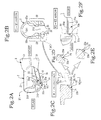
- FIG. 2A is a perspective view of the outer column in accordance with the present invention
- FIG. 2B is a cross-sectional view taken along the Y 1 -Y 1 arrows in FIG. 2A
- FIG. 2C is an enlarged view of the ( ⁇ ) portion shown in FIG. 2B
- FIG. 2D is an enlarged view of the principal portion illustrating a modification example of the inclined surface of the guide portion
- FIG. 2E is an enlarged view of the principal portion illustrating another modification example of the inclined surface of the guide portion
- FIG. 2F is a view taken along the arrowed Y 2 -Y 2 in FIG. 2C ;
- FIG. 3A is a perspective view of the pushing member in accordance with the present invention
- FIG. 3B is a view of the pushing member taken along the arrow Y 3 -Y 3 in FIG. 3A
- FIG. 3C is a front view of the first modification example of the expanding shaft portion of the pushing member
- FIG. 3D is a front view of the second modification example of the expanding shaft portion of the pushing member;
- FIG. 4A is a side view illustrating the state of the outer column and the pushing member when the outer column is fastened
- FIG. 4B is a vertical sectional front view illustrating the state of the outer column and the pushing member when the outer column is fastened
- FIG. 4C is a side view illustrating the state of the outer column and the pushing member when the fastening of the outer column is released
- FIG. 4D is a vertical sectional front view illustrating the state of the outer column and the pushing member when the fastening of the outer column is released;
- FIG. 5 is a principal enlarged view of the outer column illustrating the operation state in which the force of the expanding shaft portion of the pushing member is applied to the two fastening pieces;
- FIG. 6A is a principal enlarged view in accordance with the present invention that is provided with the second embodiment of the pushing member
- FIG. 6B is a principal view of the configuration in which the pushing member of the second embodiment is provided at the outer column in which the slot portion and the two fastening pieces are positioned on the upper side.
- a front-rear direction is set, and after the steering device in accordance with the present invention has been mounted on a vehicle, the sites corresponding to the front side on the vehicle will be described with the adjective “front” and the sites corresponding to the rear side on the vehicle will be described with the adjective “rear”, where the front-rear direction of the vehicle is taken as a reference.
- the width direction (left-right direction) in the present invention is a horizontal direction perpendicular to the front-rear direction.
- the main configuration in accordance with the present invention is constituted by an inner column 1 , an outer column 2 , a fixed bracket 4 , a fastener 6 , and a pushing member 5 .
- the inner column 1 is free to move in the front-rear direction with respect to the outer column 2 .
- a steering shaft (not shown in the figure) is rotatably mounted on the inner column 1 .
- the outer column 2 is mainly made from an aluminum alloy and, as shown in FIG. 1 and FIG. 2 , mainly constituted by an embracing body portion 21 and two fastening pieces 22 .
- the embracing body portion 21 is formed in a substantially cylindrical shape and the interior thereof has an inner peripheral surface portion 211 formed in a hollow shape.
- the embracing body portion serves to embrace the inner column 1 .
- a slot portion 212 is formed at the lower side, in the diametric direction, of the embracing body portion 21 .
- the slot portion 212 is a portion where the entire or substantially entire embracing body portion 21 is split from the front side to the rear side in the axial direction and formed in a substantially slit-like shape extending along the axial direction of the embracing body portion 21 (see FIGS. 1B , 1 C, 2 A, and 2 B).
- the two ends of the slot portion 212 in the width direction are parallel (inclusive of substantially parallel) to each other, and therefore the distance therebetween is the same (inclusive of substantially same) along the axial direction.
- the slot portion 212 can be also referred to as an opening between two fastening pieces 22 .
- the slot portion 212 can be also formed on the upper side.
- the two fastening pieces 22 are also formed above the outer column 2 .
- the two fastening pieces 22 are formed at the lower side, in the diametric direction, of the embracing body portion 21 at both sides, in the width direction, of the slot portion 212 (see FIGS. 2A and 2B ).
- the two fastening pieces 22 are formed to have the same shape of substantially thick plates, and the longitudinal direction thereof is along the axial direction of the outer column 2 .
- the two fastening pieces 22 are disposed with left-right symmetry and parallel to each other in the width direction of the slot portion 212 and formed integrally with the embracing body portion 21 .
- Each of the fastening pieces 22 is formed in a quadrangular shape or triangular shape, when viewed from the side surface side along the axial direction of the embracing body portion 21 (see FIG. 1A ).
- the surfaces of the two fastening pieces 22 on the outer side in the width direction are substantially flat surfaces and configured such that when clamped by two fixed-side portions 41 of the below-described fixed bracket 4 , the outer side surfaces of the fastening pieces 22 can be in surface contact (inclusive of substantially surface contact) with the fixed-side portions 41 .
- Fastening holes 22 a are formed in the two fastening pieces 22 in the direction perpendicular to the front-rear direction of the outer column 2 and along the width direction of the embracing body portion 21 .
- a bolt shaft 61 of the below-described fastener 6 is inserted into the fastening holes 22 a .
- an arm section 3 constituted by two arm portions 31 and a shaft support portion 32 is formed as shown in FIG. 1B .
- pivot through holes 33 are formed for pivotal connection, with a freedom of swinging, to a lower bracket 9 for tilting.
- Recesses may be provided in several locations on the outer side surface of the fastening pieces 22 with consideration for a casting scheme and weight reduction.
- Guide portions 23 that will abut on expanding shaft portion 51 of the below-described pushing member 5 are formed at the lower end of the two fastening pieces 22 and close to the locations where the fastening holes 22 a are formed (see FIG. 2A ).
- Two side edges in the opening of the slot portion 212 will be referred to herein as end zones 2 t . More specifically, in FIG. 1C and FIG. 2B , these zones are edges at the lower end locations of the two fastening pieces 22 that face each other at both sides in the width direction of the slot portion 212 .
- the aforementioned end zones 2 t become edges of the upper end zones of the two fastening pieces 22 that face each other at both sides in the width direction of the slot portion 212 (see FIG. 6B ).
- the guide portion 23 is constituted by an inclined surface 23 a and a stopper surface 23 b (see FIGS. 2A to 2F ).
- the inclined surfaces 23 a are formed at inner, mutually opposite surfaces of the fastening pieces 22 , so as to have substantially rectangular shapes extending in the front-rear directions with respect to the respective fastening pieces 22 .
- the two inclined surfaces 23 a are formed in a substantially chamfered shape that opens so that the spacing in the width direction increases outward and downward from the respective inner side surfaces of the fastening pieces 22 .
- the two inclined surfaces 23 a When viewed from the front side of the vehicle body, the two inclined surfaces 23 a appear to be formed to expand so that the gap therebetween has an inverted “V” shape that expands downward.
- the two inclined surfaces 23 a are inclined to expand from the slot portion 212 side outward in the width direction of the outer column 2 (see FIG. 2B ).
- the inclined surfaces 23 a are formed to have a cross section in the form of linear inclined surfaces (see FIGS. 2C and 2D ), or concave circular-arc surfaces (see FIG. 2D ), or convex circular-arc surfaces (see FIG. 2E ).
- the stopper surface 23 b is formed to protrude in the direction perpendicular (inclusive of substantially perpendicular) to the inclined surface 23 a at the rear end side of both inclined surfaces 23 a .
- the stopper surface 23 b is formed on the vehicle rear side with respect to the inclined surface 23 a .
- the guide portion 23 is preferably formed in the vicinity of the through holes 22 a for fastening. Further, it is preferred that the inclined surface 23 a and the stopper surface 23 b be formed continuously by a circular-arc surface.
- the fixed bracket 4 is constituted by fixed side portions 41 and an upper surface portion 42 (see FIG. 1B and FIG. 10 ).
- Support holes 41 a are formed in the fixed side portions 41 .
- the support holes 41 a are formed as elongated holes extending in the up-down direction.
- the upper surface portion 42 serves to mount the fixed bracket 4 with a fixing tool such as a bolt on a predetermined position of the vehicle body. Stop holes 42 a for attaching the pushing member 5 are formed in the upper surface portion 42 .
- the fixed bracket 4 clamps both outer side surfaces of the outer column 2 by both fixed side portions 41 and is set so that the positions of the fastening holes 22 a of the outer column 2 coincide with those of the support holes 41 a of the fixed bracket 4 .
- the bolt shaft 61 of the below-described fastening tool 6 passes therethrough (see FIGS. 1B and 1C ).
- a shock absorbing means is provided on the upper surface portion 42 of the fixed bracket 4 . Capsule members that clamp the upper surface portion 42 and are fixed with bolts to the vehicle body and a short absorbing member that deforms plastically when absorbing a shock are used as the shock absorbing means.
- the fastening tool 6 is constituted by the bolt shaft 61 , an operation level portion 62 , a fastening cam 63 , and a fastening nut 64 .
- the fastening tool 6 is mounted by the operation lever portion 62 , fastening cam 63 , and fastening nut 64 .
- By performing the operation of fastening the operation lever portion 62 of the fastening tool 6 it is possible to reduce the diameter of the inner peripheral side surface portion 211 of the embracing body portion 21 and fasten and lock fix the inner column 1 that is accommodated and mounted on the inner peripheral side surface portion 211 (see FIG. 1C ). Further, by rotating the operation lever portion 62 of the fastening tool 6 and releasing the fastened state, it is possible to increase the diameter of the inner peripheral side surface portion 211 of the embracing body portion 21 , release locking of the inner column 1 , and perform tilt telescopic adjustment.
- the pushing member can be implemented in a plurality of embodiments.
- spring portions 5 A are formed at both sides, in the width direction of the expanding shaft portion 51 .
- the spring portion 5 A serves as a means for elastically biasing the expanding shaft portion 51 upward.
- first elastic shaft portions 52 are formed to extend rearward from the front side of the expanding shaft portion 51
- return coil spring portions 53 are formed with a left-right symmetry at front axial ends of the two first elastic shaft portions 52
- second elastic shaft portions 54 are formed rearward from the two return coil spring portions 53 toward the expanding shaft portion 51
- locking shaft portions 55 are formed to extend upward from the rear axial ends of the two second elastic shaft portions 54 .
- the expanding shaft portion 51 and the spring portion 5 A are formed from a metal shaft material, and the expanding shaft portion 51 and the spring portion 5 A are formed integrally.
- the expanding shaft portion 51 is formed as a circular-arc peak protruding upward and has a shape corresponding to the inclined surfaces 23 a formed at both fastening pieces 22 .
- the expanding shaft portion 51 has a shape with left-right symmetry in the width direction and has left-right symmetrical inclined shaft pieces 51 a (see FIGS. 3B , 3 C, 3 D).
- the two inclined shaft pieces 51 a are formed as circular arcs of a substantially semispherical shape (see FIGS. 3A and 3B ).
- the two inclined shaft pieces 51 a are formed to obtain a substantially inverted “V” shape or a triangular peak shape (see FIG. 3C ).
- a horizontal shaft piece 51 b is formed in the intermediate sections of the two inclined shaft pieces 51 a to obtain a trapezoidal shape (see FIG. 3D ).
- the two inclined shaft pieces 51 a of the expanding shaft portion 51 abut on the end zones 2 t of the two fastening pieces 22 of the outer column 2 and serve to expand the two fastening pieces 22 . It is thus preferred that the expanding shaft portion 51 have a shape corresponding to the two inclined surfaces 23 a.
- the expanding shaft portion 51 substantially bridges or spans between the end zones 2 t of the two fastening pieces 22 of the outer column 2 , the first elastic shaft portions 52 , second elastic shaft portions 54 , and both return coil spring portions 53 are positioned on the outer side in the width direction of the two fastening pieces 22 , and the locking shaft portions 55 are locked and fixed to the locking holes 42 a of the upper surface portion 42 of the fixed bracket 4 (see FIGS. 1B and 1C ).
- the expanding shaft portion 51 abuts on the end zones 2 t (at the lower ends) of the two fastening pieces 22 and has a function of pushing the outer column 2 and the inner column 1 upward and preventing the steering wheel from moving downward under gravity during tilting operation.
- the expanding shaft portion 51 of the pushing member 5 abuts on the guide portions 23 formed in the (end zones 2 t of the) two fastening pieces 22 of the outer column 2 . Since the expanding shaft portion 51 abuts on the guide portions 23 , the abutment state of the two fastening pieces 22 and the expanding shaft portion 51 is in the form of surface contact (see FIGS. 2C and 2D ). Therefore, the expanding shaft portion 51 smoothly and moderately expands the two fastening pieces 22 , while elastically pushing them upward.
- the expanding shaft portion 51 abuts on the two stopper surfaces 23 b , the optimum abutment positions of the expanding shaft portion 51 and the end zones 2 t of the two fastening pieces 22 are maintained, and these optimum abutment positions are prevented from shifting to the rear side of the vehicle body.
- the two inclined shaft pieces 51 a of the expanding shaft portion 51 of the pushing member 5 are in a state of constant abutment on the end zones 2 t at the lower ends of the two fastening pieces 22 under the effect of an elastic biasing force F (see FIGS. 4A and 4B ).
- the position of the uppermost portion of the expanding shaft portion 51 of the pushing member 5 at this time is referred to as a reference position.
- the elastic biasing force F is distributed to the two inclined shaft pieces 51 a of the expanding shaft portion 51 to provide a biasing force F distributed to the inclined surfaces 23 a of the two guide portions 23 , and the two inclined shaft pieces 51 a abut obliquely on the two inclined surfaces 23 a (see FIG. 5 ).
- the biasing forces distributed in such oblique abutment state are transmitted by the two inclined surfaces 23 a to the two fastening pieces 22 .
- a vertical force component Fv acts upward and a horizontal force component Fh acts in the width direction on the fastening piece 22 via the inclined surface 23 a (of the guide portion 23 ) (see FIG. 5 ).
- the operation lever portion 62 of the fastener 6 is then rotated to release the fastening.
- the fastening of the two fixed side portions 41 of the fixed bracket 4 and the two fastening pieces 22 of the outer column 2 is relaxed (see FIGS. 4C and 4D ).
- the two inclined shaft pieces 51 a of the expanding shaft portion 51 apply horizontal force components Fh to (the end zones 2 t of) both fastening pieces 22 via the inclined surfaces 23 a of both guide portions 23 , and the embracing body portion 21 is expanded in the horizontal diametric direction about the slot portion 211 of the outer column 2 as a center.
- the inner diameter of the embracing body portion 21 is difficult to enlarge even if the fastener 6 is loosened. In other words, the fastened state of the outer column 2 is maintained.
- the two fastening pieces 22 of the outer column 2 can be forcibly expanded by performing a fastening release operation of the fastener 6 .
- the pushing member 5 generates an upward elastic biasing force F at all times and the outer column 2 and the inner column 1 are prevented from falling down during the tilt-telescopic adjustment.
- the gap between the outer column 2 and the inner column 1 can be made small during the initial setting, the gap can be prevented from getting too large when the fastening of the inner column 1 by the fastener 6 is released, and a play can be reduced.
- the elastic biasing force F acting upon the two fastening pieces 22 can maintain a substantially constant state in which the pushing member 5 is pushed against the two guide portions 23 of the two fastening pieces 22 during locking and also during lock release.
- the pushing member 5 combines two functions, namely, a function of ensuring a gap between the inner column 1 and the inner peripheral surface portion 211 of the outer column 2 during telescopic operation and a function of preventing the steering wheel from falling down under gravity during tilt-telescopic operation. Therefore, the number of parts in the steering device is decreases and the number of assembling operations is also reduced.
- the expanding shaft portion 51 and the spring portion 5 A constituting the expansion are configured as separate members.
- the expanding shaft portion 51 has a shape with left-right symmetry in the width direction and has the inclined shaft pieces 51 a symmetrical in the left-right direction.
- the two inclined shaft pieces 51 a are formed as circular-arc peaks of a substantially semicircular shape, and a circular arc symmetrical in the left-right direction is constituted by the two inclined shaft pieces 51 a.
- the two inclined shaft pieces 51 a can be formed as a peak of a substantially inverted “V”-like shape or triangular shape in the same manner as in the first embodiment, or a horizontal shaft piece 51 b can be formed between the two inclined shaft pieces 51 a to provide for a trapezoidal shape in the second modification example of the expanding shaft portion 51 .
- a tension coil spring 56 constituted by a member separate from the expanding shaft portion 51 can be used as the spring portion 5 A. Hooks 56 a are formed at both ends, in the extension-contraction direction, at the tension coil spring 56 .
- FIG. 6B is a configuration diagram illustrating an embodiment in which the slot portion 212 is positioned on the upper side of the outer column 2 .
- the pushing member 5 of the second embodiment is mounted by the tension coil spring 56 on the bolt shaft 61 so as to abut on the end zones 2 t at the upper ends of the opposing two fastening pieces 22 at both sides, in the width direction, of the slot portion 212 .
- the expanding shaft portion 51 of the pushing member 5 is elastically biased and abutted on the end zones 2 t of the two fastening pieces 22 by the elasticity of the tension coil spring portion 56 , the two fastening pieces 22 are expanded in the width direction, and the inner peripheral surface portion 211 of the embracing body portion 21 expands in the diametric direction about the slot portion 211 as a center.
- the fastening with the fastener 6 can be released, the embracing body member 21 is substantially forcibly expanded in the diametric direction by the expanding shaft member 51 of the pushing member 5 , the inner column 1 accommodated in the outer column 2 can smoothly move in the axial direction, and telescopic adjustment can be easily performed.
- the present invention should not be construed as being limited to the above-described embodiments.
- the embodiments can be changed and modified as appropriate, for example, the slot portion 212 of the outer column 2 can be provided on the upper side.
Landscapes
- Engineering & Computer Science (AREA)
- Chemical & Material Sciences (AREA)
- Combustion & Propulsion (AREA)
- Transportation (AREA)
- Mechanical Engineering (AREA)
- Steering Controls (AREA)
Applications Claiming Priority (2)
| Application Number | Priority Date | Filing Date | Title |
|---|---|---|---|
| JP2011-23190 | 2011-02-04 | ||
| JP2011023190A JP5620841B2 (ja) | 2011-02-04 | 2011-02-04 | ステアリング装置 |
Publications (2)
| Publication Number | Publication Date |
|---|---|
| US20120198956A1 US20120198956A1 (en) | 2012-08-09 |
| US8826769B2 true US8826769B2 (en) | 2014-09-09 |
Family
ID=46585568
Family Applications (1)
| Application Number | Title | Priority Date | Filing Date |
|---|---|---|---|
| US13/363,299 Expired - Fee Related US8826769B2 (en) | 2011-02-04 | 2012-01-31 | Steering device |
Country Status (3)
| Country | Link |
|---|---|
| US (1) | US8826769B2 (ja) |
| JP (1) | JP5620841B2 (ja) |
| CN (1) | CN102627119A (ja) |
Cited By (6)
| Publication number | Priority date | Publication date | Assignee | Title |
|---|---|---|---|---|
| US20140116186A1 (en) * | 2012-10-31 | 2014-05-01 | Melvin L. Tinnin | Steering column assembly with improved attachment to a vehicle structure |
| US20160059879A1 (en) * | 2014-08-30 | 2016-03-03 | Yamada Manufacturing Co., Ltd. | Steering device |
| US9849906B2 (en) | 2015-03-27 | 2017-12-26 | Fuji Kiko Co., Ltd. | Steering column device |
| US10486731B2 (en) * | 2017-08-09 | 2019-11-26 | Yamada Manufacturing Co., Ltd. | Steering apparatus |
| US20200234996A1 (en) * | 2019-01-17 | 2020-07-23 | Asm Ip Holding Bv | Vented susceptor |
| US11945495B2 (en) * | 2021-10-27 | 2024-04-02 | ZF Steering Systems Poland Sp. Z.o.o. | Steering column assembly |
Families Citing this family (15)
| Publication number | Priority date | Publication date | Assignee | Title |
|---|---|---|---|---|
| US20110088501A1 (en) * | 2009-10-20 | 2011-04-21 | Mando Corporation | Steering column for vehicle |
| JP5662115B2 (ja) * | 2010-01-20 | 2015-01-28 | 株式会社山田製作所 | ステアリング装置 |
| JP5609812B2 (ja) * | 2011-08-01 | 2014-10-22 | 日本精工株式会社 | ステアリング装置 |
| GB201208791D0 (en) * | 2012-05-18 | 2012-07-04 | Trw Ltd | Steering column assembly |
| DE102012104644B3 (de) * | 2012-05-30 | 2013-08-08 | Thyssenkrupp Presta Aktiengesellschaft | Lenksäule für ein Kraftfahrzeug |
| JP5912970B2 (ja) * | 2012-07-28 | 2016-04-27 | 株式会社山田製作所 | ステアリング装置 |
| JP5999427B2 (ja) * | 2012-11-28 | 2016-09-28 | 株式会社ジェイテクト | ステアリング装置 |
| JP5886805B2 (ja) * | 2013-09-03 | 2016-03-16 | 株式会社山田製作所 | ステアリング装置 |
| US9393987B2 (en) * | 2013-11-20 | 2016-07-19 | Nsk Ltd. | Steering apparatus |
| CN106170427B (zh) * | 2014-01-30 | 2018-07-31 | 日本精工株式会社 | 转向装置 |
| JP6344606B2 (ja) | 2014-08-19 | 2018-06-20 | 株式会社ジェイテクト | ステアリング装置 |
| JP6742167B2 (ja) * | 2016-06-21 | 2020-08-19 | 株式会社山田製作所 | ステアリング装置 |
| KR102146755B1 (ko) * | 2017-11-15 | 2020-08-21 | 남양넥스모 주식회사 | 조향 컬럼 |
| JP7251138B2 (ja) * | 2018-12-26 | 2023-04-04 | 株式会社ジェイテクト | ステアリング装置 |
| DE102020201058A1 (de) * | 2020-01-29 | 2021-07-29 | Thyssenkrupp Ag | Lenksäule für ein Kraftfahrzeug |
Citations (10)
| Publication number | Priority date | Publication date | Assignee | Title |
|---|---|---|---|---|
| US6419269B1 (en) * | 1999-09-20 | 2002-07-16 | Delphi Technologies | Locking system for adjustable position steering column |
| JP2004189152A (ja) | 2002-12-12 | 2004-07-08 | Nsk Ltd | ステアリングコラム装置 |
| US20050225068A1 (en) * | 2002-06-04 | 2005-10-13 | Ryuuichi Ishida | Tilt steering column device for vehicle |
| US20050268739A1 (en) * | 2002-07-17 | 2005-12-08 | Nsk Ltd. | Steering column device |
| JP2008162422A (ja) | 2006-12-28 | 2008-07-17 | Nsk Ltd | ステアリングコラム装置 |
| US20080202276A1 (en) * | 2005-04-19 | 2008-08-28 | Delphi Technologies, Inc. | Adjustable steering column assembly |
| US20110185839A1 (en) * | 2009-04-20 | 2011-08-04 | Nsk Ltd. | Position adjustment device for steering wheel |
| US20110203403A1 (en) * | 2010-02-19 | 2011-08-25 | Yamada Manufacturing Co., Ltd. | Steering position adjustment device |
| US20110271787A1 (en) * | 2007-08-02 | 2011-11-10 | Paul Mark Marable | Adjustable steering column assembly for a motor vehicle |
| US20130087006A1 (en) * | 2011-10-11 | 2013-04-11 | Mazda Motor Corporation | Steering column cover structure of automotive vehicle |
Family Cites Families (3)
| Publication number | Priority date | Publication date | Assignee | Title |
|---|---|---|---|---|
| JPH01223066A (ja) * | 1988-03-01 | 1989-09-06 | Hino Motors Ltd | 自動車のステアリングシャフト支持装置 |
| JP2008132891A (ja) * | 2006-11-29 | 2008-06-12 | Fuji Kiko Co Ltd | 車両用ステアリング装置 |
| JP5662115B2 (ja) * | 2010-01-20 | 2015-01-28 | 株式会社山田製作所 | ステアリング装置 |
-
2011
- 2011-02-04 JP JP2011023190A patent/JP5620841B2/ja active Active
-
2012
- 2012-01-31 US US13/363,299 patent/US8826769B2/en not_active Expired - Fee Related
- 2012-02-02 CN CN 201210023131 patent/CN102627119A/zh active Pending
Patent Citations (13)
| Publication number | Priority date | Publication date | Assignee | Title |
|---|---|---|---|---|
| US6419269B1 (en) * | 1999-09-20 | 2002-07-16 | Delphi Technologies | Locking system for adjustable position steering column |
| US20050225068A1 (en) * | 2002-06-04 | 2005-10-13 | Ryuuichi Ishida | Tilt steering column device for vehicle |
| US7354068B2 (en) * | 2002-06-04 | 2008-04-08 | Nsk Ltd. | Tilt steering column device for vehicle |
| US20050268739A1 (en) * | 2002-07-17 | 2005-12-08 | Nsk Ltd. | Steering column device |
| JP2004189152A (ja) | 2002-12-12 | 2004-07-08 | Nsk Ltd | ステアリングコラム装置 |
| US7322608B2 (en) | 2002-12-12 | 2008-01-29 | Nsk Ltd. | Steering column apparatus |
| US20080202276A1 (en) * | 2005-04-19 | 2008-08-28 | Delphi Technologies, Inc. | Adjustable steering column assembly |
| JP2008162422A (ja) | 2006-12-28 | 2008-07-17 | Nsk Ltd | ステアリングコラム装置 |
| US20110271787A1 (en) * | 2007-08-02 | 2011-11-10 | Paul Mark Marable | Adjustable steering column assembly for a motor vehicle |
| US20110185839A1 (en) * | 2009-04-20 | 2011-08-04 | Nsk Ltd. | Position adjustment device for steering wheel |
| US20110203403A1 (en) * | 2010-02-19 | 2011-08-25 | Yamada Manufacturing Co., Ltd. | Steering position adjustment device |
| US8596161B2 (en) * | 2010-02-19 | 2013-12-03 | Yamada Manufacturing Co., Ltd. | Steering position adjustment device |
| US20130087006A1 (en) * | 2011-10-11 | 2013-04-11 | Mazda Motor Corporation | Steering column cover structure of automotive vehicle |
Non-Patent Citations (1)
| Title |
|---|
| Japanese Office Action dated Jun. 3, 2014. |
Cited By (8)
| Publication number | Priority date | Publication date | Assignee | Title |
|---|---|---|---|---|
| US20140116186A1 (en) * | 2012-10-31 | 2014-05-01 | Melvin L. Tinnin | Steering column assembly with improved attachment to a vehicle structure |
| US20160059879A1 (en) * | 2014-08-30 | 2016-03-03 | Yamada Manufacturing Co., Ltd. | Steering device |
| US9540031B2 (en) * | 2014-08-30 | 2017-01-10 | Yamada Manufacturing Co., Ltd. | Steering device |
| US9849906B2 (en) | 2015-03-27 | 2017-12-26 | Fuji Kiko Co., Ltd. | Steering column device |
| US10486731B2 (en) * | 2017-08-09 | 2019-11-26 | Yamada Manufacturing Co., Ltd. | Steering apparatus |
| US20200234996A1 (en) * | 2019-01-17 | 2020-07-23 | Asm Ip Holding Bv | Vented susceptor |
| US11961756B2 (en) * | 2019-01-17 | 2024-04-16 | Asm Ip Holding B.V. | Vented susceptor |
| US11945495B2 (en) * | 2021-10-27 | 2024-04-02 | ZF Steering Systems Poland Sp. Z.o.o. | Steering column assembly |
Also Published As
| Publication number | Publication date |
|---|---|
| CN102627119A (zh) | 2012-08-08 |
| JP2012162152A (ja) | 2012-08-30 |
| JP5620841B2 (ja) | 2014-11-05 |
| US20120198956A1 (en) | 2012-08-09 |
Similar Documents
| Publication | Publication Date | Title |
|---|---|---|
| US8826769B2 (en) | Steering device | |
| KR101520818B1 (ko) | 스티어링 컬럼 조립체용 클램프조립체 | |
| JP5662115B2 (ja) | ステアリング装置 | |
| JP6028872B2 (ja) | ステアリング装置 | |
| US9540031B2 (en) | Steering device | |
| JP5912970B2 (ja) | ステアリング装置 | |
| JP2009045992A (ja) | ステアリングホィールの位置調整装置 | |
| JP2005075250A (ja) | テレスコピック機構付衝撃吸収式ステアリングコラム装置 | |
| CN107521550B (zh) | 操舵装置 | |
| KR100599483B1 (ko) | 스티어링 컬럼의 팝업 방지 구조 | |
| US11273859B2 (en) | Steering device | |
| JP6390295B2 (ja) | ステアリング装置 | |
| KR20080090912A (ko) | 플레인 와셔를 구비한 틸트 앤 텔레스코픽 조향장치 | |
| JP2017035999A (ja) | ステアリング装置 | |
| JP5277103B2 (ja) | ステアリングコラム装置 | |
| JP2018039330A (ja) | ステアリング装置 | |
| KR20170117765A (ko) | 자동차의 스티어링 컬럼 틸팅장치 | |
| JP2016190522A (ja) | ステアリングコラム装置 | |
| JP6680571B2 (ja) | ステアリング装置 | |
| WO2022102359A1 (ja) | ステアリング装置 | |
| KR101931312B1 (ko) | 차량의 조향컬럼용 틸트장치 | |
| JP2011111019A (ja) | ステアリングコラム装置 | |
| JP2018030540A (ja) | ステアリング装置 | |
| JP6661447B2 (ja) | ステアリング装置 | |
| JP2021037791A (ja) | ステアリングコラム装置 |
Legal Events
| Date | Code | Title | Description |
|---|---|---|---|
| AS | Assignment |
Owner name: YAMADA MANUFACTURING CO., LTD., JAPAN Free format text: ASSIGNMENT OF ASSIGNORS INTEREST;ASSIGNORS:TAKEZAWA, NAOYUKI;SATO, YOSHIYUKI;REEL/FRAME:027824/0225 Effective date: 20111209 |
|
| STCF | Information on status: patent grant |
Free format text: PATENTED CASE |
|
| FEPP | Fee payment procedure |
Free format text: PAYOR NUMBER ASSIGNED (ORIGINAL EVENT CODE: ASPN); ENTITY STATUS OF PATENT OWNER: LARGE ENTITY |
|
| MAFP | Maintenance fee payment |
Free format text: PAYMENT OF MAINTENANCE FEE, 4TH YEAR, LARGE ENTITY (ORIGINAL EVENT CODE: M1551) Year of fee payment: 4 |
|
| FEPP | Fee payment procedure |
Free format text: MAINTENANCE FEE REMINDER MAILED (ORIGINAL EVENT CODE: REM.); ENTITY STATUS OF PATENT OWNER: LARGE ENTITY |
|
| LAPS | Lapse for failure to pay maintenance fees |
Free format text: PATENT EXPIRED FOR FAILURE TO PAY MAINTENANCE FEES (ORIGINAL EVENT CODE: EXP.); ENTITY STATUS OF PATENT OWNER: LARGE ENTITY |
|
| STCH | Information on status: patent discontinuation |
Free format text: PATENT EXPIRED DUE TO NONPAYMENT OF MAINTENANCE FEES UNDER 37 CFR 1.362 |
|
| FP | Lapsed due to failure to pay maintenance fee |
Effective date: 20220909 |