US8726514B2 - Panel manufacturing method - Google Patents
Panel manufacturing method Download PDFInfo
- Publication number
- US8726514B2 US8726514B2 US13/677,436 US201213677436A US8726514B2 US 8726514 B2 US8726514 B2 US 8726514B2 US 201213677436 A US201213677436 A US 201213677436A US 8726514 B2 US8726514 B2 US 8726514B2
- Authority
- US
- United States
- Prior art keywords
- adhesive
- outer plate
- inner plate
- panel
- plate
- Prior art date
- Legal status (The legal status is an assumption and is not a legal conclusion. Google has not performed a legal analysis and makes no representation as to the accuracy of the status listed.)
- Active
Links
Images


Classifications
-
- B—PERFORMING OPERATIONS; TRANSPORTING
- B21—MECHANICAL METAL-WORKING WITHOUT ESSENTIALLY REMOVING MATERIAL; PUNCHING METAL
- B21D—WORKING OR PROCESSING OF SHEET METAL OR METAL TUBES, RODS OR PROFILES WITHOUT ESSENTIALLY REMOVING MATERIAL; PUNCHING METAL
- B21D39/00—Application of procedures in order to connect objects or parts, e.g. coating with sheet metal otherwise than by plating; Tube expanders
- B21D39/02—Application of procedures in order to connect objects or parts, e.g. coating with sheet metal otherwise than by plating; Tube expanders of sheet metal by folding, e.g. connecting edges of a sheet to form a cylinder
- B21D39/021—Application of procedures in order to connect objects or parts, e.g. coating with sheet metal otherwise than by plating; Tube expanders of sheet metal by folding, e.g. connecting edges of a sheet to form a cylinder for panels, e.g. vehicle doors
-
- B—PERFORMING OPERATIONS; TRANSPORTING
- B21—MECHANICAL METAL-WORKING WITHOUT ESSENTIALLY REMOVING MATERIAL; PUNCHING METAL
- B21D—WORKING OR PROCESSING OF SHEET METAL OR METAL TUBES, RODS OR PROFILES WITHOUT ESSENTIALLY REMOVING MATERIAL; PUNCHING METAL
- B21D39/00—Application of procedures in order to connect objects or parts, e.g. coating with sheet metal otherwise than by plating; Tube expanders
- B21D39/02—Application of procedures in order to connect objects or parts, e.g. coating with sheet metal otherwise than by plating; Tube expanders of sheet metal by folding, e.g. connecting edges of a sheet to form a cylinder
- B21D39/028—Reinforcing the connection otherwise than by deforming, e.g. welding
-
- B—PERFORMING OPERATIONS; TRANSPORTING
- B21—MECHANICAL METAL-WORKING WITHOUT ESSENTIALLY REMOVING MATERIAL; PUNCHING METAL
- B21D—WORKING OR PROCESSING OF SHEET METAL OR METAL TUBES, RODS OR PROFILES WITHOUT ESSENTIALLY REMOVING MATERIAL; PUNCHING METAL
- B21D47/00—Making rigid structural elements or units, e.g. honeycomb structures
- B21D47/04—Making rigid structural elements or units, e.g. honeycomb structures composite sheet metal profiles
-
- B—PERFORMING OPERATIONS; TRANSPORTING
- B23—MACHINE TOOLS; METAL-WORKING NOT OTHERWISE PROVIDED FOR
- B23K—SOLDERING OR UNSOLDERING; WELDING; CLADDING OR PLATING BY SOLDERING OR WELDING; CUTTING BY APPLYING HEAT LOCALLY, e.g. FLAME CUTTING; WORKING BY LASER BEAM
- B23K26/00—Working by laser beam, e.g. welding, cutting or boring
- B23K26/08—Devices involving relative movement between laser beam and workpiece
- B23K26/0869—Devices involving movement of the laser head in at least one axial direction
- B23K26/0876—Devices involving movement of the laser head in at least one axial direction in at least two axial directions
- B23K26/0884—Devices involving movement of the laser head in at least one axial direction in at least two axial directions in at least in three axial directions, e.g. manipulators, robots
-
- B—PERFORMING OPERATIONS; TRANSPORTING
- B23—MACHINE TOOLS; METAL-WORKING NOT OTHERWISE PROVIDED FOR
- B23K—SOLDERING OR UNSOLDERING; WELDING; CLADDING OR PLATING BY SOLDERING OR WELDING; CUTTING BY APPLYING HEAT LOCALLY, e.g. FLAME CUTTING; WORKING BY LASER BEAM
- B23K26/00—Working by laser beam, e.g. welding, cutting or boring
- B23K26/20—Bonding
- B23K26/21—Bonding by welding
- B23K26/24—Seam welding
- B23K26/244—Overlap seam welding
-
- B—PERFORMING OPERATIONS; TRANSPORTING
- B23—MACHINE TOOLS; METAL-WORKING NOT OTHERWISE PROVIDED FOR
- B23K—SOLDERING OR UNSOLDERING; WELDING; CLADDING OR PLATING BY SOLDERING OR WELDING; CUTTING BY APPLYING HEAT LOCALLY, e.g. FLAME CUTTING; WORKING BY LASER BEAM
- B23K26/00—Working by laser beam, e.g. welding, cutting or boring
- B23K26/20—Bonding
- B23K26/21—Bonding by welding
- B23K26/24—Seam welding
- B23K26/26—Seam welding of rectilinear seams
-
- B—PERFORMING OPERATIONS; TRANSPORTING
- B23—MACHINE TOOLS; METAL-WORKING NOT OTHERWISE PROVIDED FOR
- B23K—SOLDERING OR UNSOLDERING; WELDING; CLADDING OR PLATING BY SOLDERING OR WELDING; CUTTING BY APPLYING HEAT LOCALLY, e.g. FLAME CUTTING; WORKING BY LASER BEAM
- B23K37/00—Auxiliary devices or processes, not specially adapted to a procedure covered by only one of the preceding main groups
- B23K37/04—Auxiliary devices or processes, not specially adapted to a procedure covered by only one of the preceding main groups for holding or positioning work
- B23K37/047—Auxiliary devices or processes, not specially adapted to a procedure covered by only one of the preceding main groups for holding or positioning work moving work to adjust its position between soldering, welding or cutting steps
-
- B—PERFORMING OPERATIONS; TRANSPORTING
- B23—MACHINE TOOLS; METAL-WORKING NOT OTHERWISE PROVIDED FOR
- B23K—SOLDERING OR UNSOLDERING; WELDING; CLADDING OR PLATING BY SOLDERING OR WELDING; CUTTING BY APPLYING HEAT LOCALLY, e.g. FLAME CUTTING; WORKING BY LASER BEAM
- B23K2101/00—Articles made by soldering, welding or cutting
- B23K2101/006—Vehicles
-
- B—PERFORMING OPERATIONS; TRANSPORTING
- B23—MACHINE TOOLS; METAL-WORKING NOT OTHERWISE PROVIDED FOR
- B23K—SOLDERING OR UNSOLDERING; WELDING; CLADDING OR PLATING BY SOLDERING OR WELDING; CUTTING BY APPLYING HEAT LOCALLY, e.g. FLAME CUTTING; WORKING BY LASER BEAM
- B23K2101/00—Articles made by soldering, welding or cutting
- B23K2101/18—Sheet panels
-
- Y—GENERAL TAGGING OF NEW TECHNOLOGICAL DEVELOPMENTS; GENERAL TAGGING OF CROSS-SECTIONAL TECHNOLOGIES SPANNING OVER SEVERAL SECTIONS OF THE IPC; TECHNICAL SUBJECTS COVERED BY FORMER USPC CROSS-REFERENCE ART COLLECTIONS [XRACs] AND DIGESTS
- Y10—TECHNICAL SUBJECTS COVERED BY FORMER USPC
- Y10T—TECHNICAL SUBJECTS COVERED BY FORMER US CLASSIFICATION
- Y10T29/00—Metal working
- Y10T29/49—Method of mechanical manufacture
- Y10T29/49616—Structural member making
- Y10T29/49623—Static structure, e.g., a building component
- Y10T29/49629—Panel
-
- Y—GENERAL TAGGING OF NEW TECHNOLOGICAL DEVELOPMENTS; GENERAL TAGGING OF CROSS-SECTIONAL TECHNOLOGIES SPANNING OVER SEVERAL SECTIONS OF THE IPC; TECHNICAL SUBJECTS COVERED BY FORMER USPC CROSS-REFERENCE ART COLLECTIONS [XRACs] AND DIGESTS
- Y10—TECHNICAL SUBJECTS COVERED BY FORMER USPC
- Y10T—TECHNICAL SUBJECTS COVERED BY FORMER US CLASSIFICATION
- Y10T29/00—Metal working
- Y10T29/49—Method of mechanical manufacture
- Y10T29/49826—Assembling or joining
- Y10T29/49906—Metal deforming with nonmetallic bonding
-
- Y—GENERAL TAGGING OF NEW TECHNOLOGICAL DEVELOPMENTS; GENERAL TAGGING OF CROSS-SECTIONAL TECHNOLOGIES SPANNING OVER SEVERAL SECTIONS OF THE IPC; TECHNICAL SUBJECTS COVERED BY FORMER USPC CROSS-REFERENCE ART COLLECTIONS [XRACs] AND DIGESTS
- Y10—TECHNICAL SUBJECTS COVERED BY FORMER USPC
- Y10T—TECHNICAL SUBJECTS COVERED BY FORMER US CLASSIFICATION
- Y10T29/00—Metal working
- Y10T29/49—Method of mechanical manufacture
- Y10T29/49826—Assembling or joining
- Y10T29/49947—Assembling or joining by applying separate fastener
- Y10T29/49966—Assembling or joining by applying separate fastener with supplemental joining
- Y10T29/49968—Metal fusion joining
-
- Y—GENERAL TAGGING OF NEW TECHNOLOGICAL DEVELOPMENTS; GENERAL TAGGING OF CROSS-SECTIONAL TECHNOLOGIES SPANNING OVER SEVERAL SECTIONS OF THE IPC; TECHNICAL SUBJECTS COVERED BY FORMER USPC CROSS-REFERENCE ART COLLECTIONS [XRACs] AND DIGESTS
- Y10—TECHNICAL SUBJECTS COVERED BY FORMER USPC
- Y10T—TECHNICAL SUBJECTS COVERED BY FORMER US CLASSIFICATION
- Y10T403/00—Joints and connections
- Y10T403/49—Member deformed in situ
- Y10T403/4966—Deformation occurs simultaneously with assembly
Definitions
- the present invention relates to a manufacturing method of double-wall panels composed of an outer plate and an inner plate, and more specifically to a manufacturing method of door panels for industrial equipment, automobile bonnet panels, etc.
- Double-wall door panels composed of an outer plate and an inner plate are commonly found in, e.g., side doors for industrial equipment.
- the door panel's inner plate has a plurality of bottom portions and ridge portions.
- the bottom portions of the inner plate are bonded to the outer plate with adhesive.
- an outer edge portion of the outer plate is bent inward to roll over an outer edge portion of the inner plate, and then pressed (hemming operation).
- the above is a method of fixing the outer plate and the inner plate to each other (see Patent Literature 1 for example).
- a foaming material may be placed between the outer plate and the ridge portions of the inner plate, to fill the inner space for reducing vibration and noises.
- Patent Literature 1 JP-A H09-228412 Gazette
- An object of the present invention is to provide a panel manufacturing method which can be adapted easily to manufacture of panels, such as door panels, of different sizes.
- the present invention provides a panel manufacturing method for a panel made of an outer plate integrated with an inner plate.
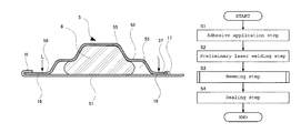
- the method includes: a step of applying an adhesive to a predetermined place on the outer plate; a step of mating the outer plate and the inner plate with each other and providing preliminary bonding by laser welding; a step of hemming by bending an outer edge portion of the pre-bonded outer plate to wrap over a circumferential edge portions of the inner plate and then pressing flat; and a step of sealing the panel by applying an adhesive to the panel after completion of the hemming step performed to the outer plate's circumferential edge portion.
- the hemming step may be performed in three or more sub-steps each involving the bending operation.
- the hemming step may include a sub step of bending and swaging mutually opposing intermediate portions in two longer sides of a rectangular panel; a sub step of bending and swaging a portion from one of the two short sides of the panel to the previously swaged intermediate portions; and a sub step of bending and swaging a portion from the remaining short side to the already swaged intermediate portions of the panel.
- the adhesive in the adhesive application step and the adhesive in the sealing step may be supplied from a same adhesive tank. Further, the adhesive may be supplied from the adhesive tank to an adhesive supply device via pipes provided with a plurality of temperature sensors and a plurality of heaters controlled in relation to the temperature sensors. With this arrangement, each of the heaters is controlled independently from the others based on an output from a corresponding one of the temperature sensors.
- the present invention makes it easy to handle manufacture of panels, such as door panels, of different sizes, and thus enables efficient manufacture of different kinds of panels.
- FIG. 1 is a perspective view of a door panel manufactured by a method according to the present invention.
- FIG. 2 is a schematic sectional view of a primary portion of the door panel manufactured by the method according to the present invention.
- FIG. 3 is a schematic sectional view of a primary portion of the door panel manufactured by the method according to the present invention.
- FIG. 4 is a flow chart showing steps in the manufacturing method according to the present invention.
- FIG. 5 is a flow chart showing a hemming step in the manufacturing method according to the present invention.
- FIG. 6 is a schematic exploded perspective view showing regions of adhesive application in the manufacturing method according to the present invention.
- FIG. 7 is a block diagram showing adhesive application equipment used in the present invention.
- FIG. 8 is a schematic diagram showing an adhesive applicator apparatus for application of an adhesive used in the present invention.
- FIG. 9 is a schematic diagram showing laser welding apparatus used in the present invention.
- FIG. 10 is a schematic diagram showing hemming equipment used in the present invention.
- FIG. 11 is a schematic diagram showing a hemming step according to the present invention.
- FIG. 12 is a schematic diagram showing a hemming step used in the present invention.
- FIG. 13 is a schematic diagram showing a hemming operation performed to panels of different sizes, according to the present invention.
- FIG. 14 is a schematic sectional view showing a state of sealing agent application according to the present invention.
- the door panel manufactured by the embodiment is a door panel for side door of a radiator room in industrial equipment for example.
- FIG. 1 through FIG. 3 show a door panel 5 for a side door.
- the door panel 5 includes an outer plate 51 ; an inner plate 52 which is pressed into a corrugated shape, with its bottom portions fixed to an inner surface of the outer plate 51 while its ridge portions providing a space 53 between the inner plate and the outer plate 51 ; and a foam material 6 which is placed and set to fill the space 53 between the outer plate 51 and the inner plate 52 .
- the outer plate 51 and the inner plate 52 are provided with four rows of vent openings 50 .
- the inner plate 52 includes an open-side bond part 57 and an outer-side bond part 58 which are portions bonded to the outer plate 51 ; and a ridge portion 55 which is formed to bulge out of the bond parts 57 , 58 , away from the outer plate 51 .
- an outer circumferential edge of the outer plate 51 includes a hemmed portion H, i.e., a portion which is bent over to wrap a circumferential edge of the inner plate 52 and then pressed flat thereby seaming the circumferential edge of the inner plate 52 .
- the bond parts 57 , 58 in the inner plate 52 are bonded to the outer plate 51 first with a bonding adhesive 16 .
- the bonding adhesive 16 provides bonding and sealing between the outer plate 51 and the bond parts 57 , 58 of the inner plate 52 .
- the inner plate 52 has a larger vent opening 50 b surrounding a vent opening 50 a in the outer plate 51 .
- a sealing agent 17 is applied along the edge of the vent opening 50 b .
- the sealing agent 17 is provided by the same adhesive as an adhesive 16 .
- the adhesive may be a paste type structural adhesive which has a sufficiently high viscosity to maintain its shape as it is applied, and appropriate thermosetting characteristics.
- An example of the paste type structural adhesive is thermosetting epoxy adhesive.
- the adhesive 16 may not necessarily be a thermosetting adhesive. Other adhesives which are usable include ultraviolet-setting adhesive, visible-light-setting adhesive, etc.
- the sealing agent 17 is applied along the edge of the vent opening 50 b of the inner plate 52 , to form a wide adhesion covering region from an adhesion covering region 51 b on the outer plate 51 which is adjacent to an opening cutout surface 52 a in the inner plate 52 to an opening-edge adhesion covering region 52 b on the inner plate 52 which is adjacent to an edge of the opening in the inner plate 52 .
- the bond parts now have improved durability. Also, since the sealing agent 17 is provided by adhesive, bonding strength is also improved.
- the ridge portion 55 has superb sectional performances in terms of second moment of area for example, so as not to be deformed easily by such a force as bending stress.
- laser tack weld is performed at an appropriate interval such as 10 mm through 1000 mm to the bond parts 57 , 58 between the inner plate 52 and the outer plate 51 .
- laser application is made from the inner plate 52 side so that no weld marks will be visible on the side where the outer plate 51 is exposed.
- Laser output and laser application time is controlled so that only a part of the outer plate 51 which is in contact with the inner plate 52 will become molten to provide weldment.
- the outer plate 51 is 1.2 through 5 times thicker than the inner plate 52 .
- the inner plate 52 is made of a steel plate which is thinner than that of the outer plate 51 .
- the outer plate 51 is made of a steel plate having a 1.2 mm thickness
- the foam material 6 is, for example, first bonded as a sheet which has not undergone a foaming step, to an inner surface of the inner plate 52 , and then heated to foam in a space between the outer plate 51 and the inner plate 52 .
- the foaming material is preferably provided by a sound absorbing rubber material which has high foamability and a volumetric expansion coefficient of 20 approximately. Heating of the foaming material may be made simultaneously with baked coating, using a baking finish furnace.
- an adhesive 16 is applied to predetermined places on the outer plate 51 using adhesive application equipment (Step S 1 ). As shown in FIG. 6 , the adhesive 16 is applied along the outer circumference and along the openings 50 a of the outer plate 51 .
- the adhesive 16 and the sealing agent 17 which will be described later are provided by the same adhesive. Therefore, the same adhesive from the same adhesive tank is supplied to adhesive application equipment for the adhesive 16 for bonding of the outer plate 51 and the inner plate 52 , as well as to adhesive application equipment for application of the sealing agent 17 at predetermined consistent conditions such as adhesive viscosity.
- the adhesive application equipment will be described later.
- the outer plate 51 and the inner plate 52 are aligned with each other as shown in FIG. 6 , and then preliminary bonded to each other.
- the preliminary bonding is performed by means of laser welding (Step S 2 ).
- FIG. 9 is a schematic diagram of an apparatus used for the laser welding. It includes a robot 70 which has a tip portion provided with laser equipment 71 .
- the door panel 5 as a bonded assembly of the outer plate 51 and the inner plate 52 is set on a stage 72 .
- the laser equipment 71 uses a YAG laser for example.
- laser welding is performed to the bond parts 57 , 58 between the inner plate 52 and the outer plate 51 at an appropriate interval of 10 mm through 1000 mm. Sweeping operation of the laser equipment 71 is performed by the robot 70 as it moves the laser equipment 71 to predetermined positions on the inner plate 52 .
- the laser equipment 71 sweeps, the laser beam is applied to the inner plate 52 .
- This laser welding is only to the extent to provide preliminary bonding. Laser output and laser application time is controlled so that only a part of the outer plate 51 which is in contact with the inner plate 52 will be welded but no weld marks will be visible on the side where the outer plate 51 is exposed.
- the welding should be accompanied by air-blowing since the welding produces a large amount of sparks which can damage a lens at the tip of the laser equipment 71 .
- the laser welding must be performed in such a spot making sequence as not deforming the welded product.
- the above embodiment uses an arrangement where the robot 70 moves the laser equipment 71 for the welding operation.
- the stage 72 may be configured for movement in XYZ directions, so that the door panel 5 can be moved for the laser welding.
- the product By using laser welding for the preliminary bonding operation, the product will be free of dents which are unavoidable in spot welding, and the laser welding process improves quality of external appearance.
- Step S 3 hemming is performed (Step S 3 ), in which the outer circumferential edge of the outer plate 51 is bent over, to wrap the circumferential edge of the inner plate 52 , and then pressed flatly.
- the outer circumferential edge of the outer plate 51 is tucked over the circumferential edge of the inner plate 52 , whereby the two are seamed with each other.
- the hemming operation according to the present invention includes three or more steps to achieve the overall bending procedure. In the present embodiment three kinds of mold are prepared, and the operation is performed in three steps, so that different types of door panels can be processed.
- FIG. 10 As shown in FIG. 10 , three pieces of hemming equipment 81 , 82 , 83 are employed in the present embodiment, so that pressing procedures in the hemming operation can be performed to different places of the panel.
- FIG. 10 and a flowchart in FIG. 5 to describe the hemming operation according to the present invention.
- the hemming equipment 81 is the first to work in this hemming operation, by working on intermediate portions in two mutually opposed sides of a rectangular door panel 5 .
- the door panel 5 in process is placed in a stage 84 , and is transported by a transportation conveyor (not illustrated) to a predetermined position in the hemming equipment 81 .
- the intermediate portion on each of the long sides in the rectangular door panel 5 is bent and swaged first (Step S 11 ).
- the door panel 5 is sent to the hemming equipment 82 for the next step of the hemming operation. Specifically, after the hemming is performed to the intermediate portions, the door panel 5 is sent to a next stage 85 , and then transported to a predetermined position in the hemming equipment 82 by a transportation conveyor (not illustrated).
- This pressing equipment 82 bends and swages a portion from one of the two short sides to the swaged intermediate portions of the rectangular door panel 5 (Step S 12 ). In the present embodiment, the swaging is made from the left short side through the swaged intermediate portions.
- the door panel 5 is sent to the hemming equipment 83 for the next step of the hemming operation. Specifically, after the hemming is performed to the intermediate portions and the left side portion, the door panel 5 is transported to a predetermined position in the hemming equipment 83 by a transportation conveyor (not illustrated).
- This pressing equipment 83 bends and swages a portion from remaining one of the two short sides to the swaged intermediate portions of the rectangular door panel 5 (Step S 13 ). In the present embodiment, the swaging is made from the right short side through the swaged intermediate portions.
- FIG. 11 shows an example of working on a door panel 5 which has the longest handleable pattern
- FIG. 12 shows an example of working on a door panel which has the shortest handleable pattern.
- FIG. 11 and FIG. 12 show bent-and-flattened regions c in broken lines while the figures also show swaged regions in alternate long and short dash lines H 1 as well as in alternate long and two short dashes lines H 2 , H 3 .
- FIG. 11 and FIG. 12 show two door panels 5 , 5 as examples, which have an equal length in their short sides but different lengths in their long sides.
- first, swaging is performed to intermediate portions in two mutually opposed long sides as indicated by the alternate long and short dash lines H 1 .
- swaging is performed to a region indicated by the alternate long and two short dashes lines H 2 , which is an edge region ranging from the left short-side and to the swaged regions H 1 in the middle of the long sides of the door panel 5 a .
- the swaging indicated by the alternate long and short dash lines H 1 and the swaging indicated by the alternate long and two short dashes lines H 2 become continuous to each other in the longer door panel 5 which is shown in FIG. 11 .
- the swaging indicated by the alternate long and short dash lines H 1 and the swaging indicated by the alternate long and two short dashes lines H 2 are overlapped with each other as shown in FIG. 12 .
- swaging is performed to a region indicated by an alternate long and two short dashes lines H 3 , which is an edge region ranging from the right short-side and to the swaged regions H 1 in the middle of the long sides of the door panel 5 .
- the swaging indicated by the alternate long and short dash lines H 1 and the swaging indicated by the alternate long and two short dashes lines H 3 become continuous to each other in the longer door panel 5 in FIG. 11 .
- the swaging indicated by the alternate long and short dash lines H 1 and the swaging indicated by the alternate long and two short dashes lines H 3 are overlapped with each other as shown in FIG. 12 .
- a maximum length A is the length which is achievable by the three hemming operations to make one continuous swaging lines.
- a minimum length B is the length which is achievable by the left-side and the right-side hemming operations without making overlaps with each other.
- a length D which is obtained by subtracting the length B from the length A, is a variable range in length. Door panels 5 falling in this size range are handleable by the present invention.
- the process is performed in steps, i.e., starting from an intermediate portion, then the right side, and finally the left side of the door.
- the door panel 5 is brought to adhesive application equipment for application of an adhesive in a sealing operation (Step S 4 ).
- an adhesive from a sealing agent supply device 10 b is applied as the sealing agent 17 over a wide adhesion covering region along opening cutout surface which defines a perimeter of the vent opening 50 b in the inner plate 52 , from an adhesion covering region 51 b on the outer plate 51 which is adjacent to the opening cutout surface 52 a of the inner plate 52 , to an opening edge adhesion covering region 52 b on the inner plate 52 which is adjacent to the opening cutout surface 52 a of the inner plate 52 .
- the outer plate 51 and the inner plate 52 are then placed in a bake-coating oven to allow setting of the thermosetting bonding adhesive 16 applied therebetween and thereby bonding the outer plate 51 and the inner plate 52 with each other as well as allowing the foaming material to foam thermally.
- heating in the bake-coating oven gives baked finish to the outer surfaces of the outer plate 51 and the inner plate 52 by curing the paint which was sprayed on the surfaces in advance.
- the adhesive 16 and the sealing agent 17 may be set at heating at a temperature of 160 degrees Celsius for ten minutes whereas baking to the coating may be achieved by heating at a temperature of 180 degrees Celsius through 200 degrees Celsius for twenty minutes. These heating operations can be achieved by using a existing bake-coating oven.
- Door panels can thus be manufactured by following the method described above.
- the adhesive 16 and the sealing agent 17 are provided by the same adhesive. Therefore, the same adhesive from the same adhesive tank 11 is supplied to supply devices 10 ( 10 a , 10 b ), for application of the adhesive 16 for bonding the outer plate 51 and the inner plate 52 with each other, as well as for application of the sealing agent 17 , under predetermined consistent conditions such as a consistent adhesive viscosity.
- FIG. 7 is a block diagram showing a configuration of the adhesive application equipment used in the present invention
- FIG. 8 is a schematic diagram showing an adhesive applicator apparatus for application of the adhesive.
- the adhesive applicator apparatus is a robot 100 including a tip portion having an adhesive cartridge holder, and the adhesive supply device 10 ( 10 a , 10 b ) for dispensing a predetermined amount of adhesive which is squeezed from the adhesive cartridge inside the holder.
- the adhesive supply device 10 ( 10 a , 10 b ) has a lower end provided with an adhesive application nozzle.
- the robot 100 is capable of moving the adhesive application nozzle of the adhesive supply device 10 ( 10 a , 10 b ) to anywhere according to operation programs based on e.g. three-dimensional coordinate values and speed commands, as well as controlling the amount of the adhesive supplied from the adhesive supply device 10 ( 10 a, 10 b ) by controlling adhesive squeezing pressure.
- the adhesive application equipment used in the present invention includes an adhesive tank 11 to store the adhesive. From this adhesive tank 11 , the adhesive is supplied via pipes 12 , to the adhesive supply device 10 a which applies the adhesive 16 for bonding of the door panel 5 , and to the adhesive supply device 10 b which applies the adhesive 16 as the sealing agent.
- the adhesive is subject to changes in viscosity for example, at different temperatures, and becomes impossible to maintain a predetermined adhesive fluidity. This result in a problem that the amount of adhesive applied is inconsistent.
- the present invention provides an arrangement that temperatures in the pipes 12 are measured by a plurality of temperature sensors 131 through 136 , and based on outputs from these sensors, a controller 15 controls outputs from heaters 141 through 145 which control the temperature in the pipes 12 . In this way, the temperature of the adhesive inside the pipes 12 is maintained at a desirable level within a range from 20 through 40 degrees, thereby maintaining the adhesive fluidity stably, eliminating variations in the amount of adhesive applied, and providing stability in the bonding and sealing.
- piping has two routes, i.e., one provided by pipes 12 a from the adhesive tank 11 to the adhesive supply device 10 a used for bonding the door panel 5 , and the other provided by pipes 12 b to the adhesive supply device 10 b used for applying the sealing agent to the door panel 5 .
- These pipes 12 a , 12 b have the same length, each being provided with temperature sensors at three locations.
- the pipes 12 a are provided with sensors 131 , 132 , 133 whereas the pipes 12 b are provided with sensors 134 , 135 , 136 .
- the adhesive tank 11 is away from the first sensors 131 , 134 by the same distance L 1 . Likewise, the first sensors are away from their corresponding second sensors, and the second sensors are away from their corresponding third sensor is by the same distance I.
- heaters 141 , 142 , 143 , 144 , 145 are provided around the pipes 12 , 12 a , 12 b , and the controller 15 controls outputs of these heaters based on the corresponding sensors so that the temperature of the adhesive inside the pipes is maintained at a substantially consistent level, i.e., within a range from a predetermined temperature to the temperature.
- the invention makes it possible to reliably perform quality control operations on, e.g. adhesive application to the inner plate regions and adhesive application patterns for corking purposes, making the invention applicable to highly demanding design requirements as found in important structural body parts.
- the invention also provides an advantage that use of adhesive as the sealing agent 17 improves sealing performance and bonding strength.
- the adhesive supply device 10 ( 10 a , 10 b ) is moved by the robot 100 for adhesive application.
- the stage which supports the door panel 5 may be configured for movement in XYZ directions, so that the door panel 5 can be moved for the adhesive application.
- the adhesive 16 and the sealing agent 17 are provided by a thermosetting adhesive.
- the adhesive 16 and the sealing agent 17 may be provided by an ultraviolet-setting adhesive or visible-light-setting adhesive for example.
- UV lights are employed in the adhesive setting step to apply ultraviolet rays.
- the adhesive is directly irradiated with ultraviolet rays from the ultraviolet lights to cure the adhesive.
- Ultraviolet-setting adhesive can shorten the curing step since it cures quickly as it receives ultraviolet rays.
- the arrangement may require deodorization equipment since ultraviolet rays applied to atmospheric air will produce ozone.
- the adhesive curing step may be achieved by employing fluorescent lighting equipment for example, so that the adhesive is irradiated with visible light from the fluorescent light tubes. With an irradiation process at an approximately 70,000 luxes from 27 Watt fluorescent light tubes for about two minutes, it is possible to cure the adhesive 16 and the sealing agent 17 .
- Use of fluorescent lights tubes in the adhesive curing step does not produce any ozone so there is no need to provide deodorization equipment. Also, the arrangement can shorten the time required for the curing step as compared to arrangements with a thermosetting adhesive since it requires a shorter curing time of approximately two minutes.
Landscapes
- Engineering & Computer Science (AREA)
- Physics & Mathematics (AREA)
- Optics & Photonics (AREA)
- Mechanical Engineering (AREA)
- Plasma & Fusion (AREA)
- Robotics (AREA)
- Automobile Manufacture Line, Endless Track Vehicle, Trailer (AREA)
- Securing Of Glass Panes Or The Like (AREA)
- Superstructure Of Vehicle (AREA)
Applications Claiming Priority (3)
| Application Number | Priority Date | Filing Date | Title |
|---|---|---|---|
| JP2010166610 | 2010-07-25 | ||
| JP2010-166610 | 2010-07-25 | ||
| PCT/JP2011/066529 WO2012014766A1 (ja) | 2010-07-25 | 2011-07-21 | パネルの製造方法 |
Related Parent Applications (1)
| Application Number | Title | Priority Date | Filing Date |
|---|---|---|---|
| PCT/JP2011/066529 Continuation WO2012014766A1 (ja) | 2010-07-25 | 2011-07-21 | パネルの製造方法 |
Publications (2)
| Publication Number | Publication Date |
|---|---|
| US20130074314A1 US20130074314A1 (en) | 2013-03-28 |
| US8726514B2 true US8726514B2 (en) | 2014-05-20 |
Family
ID=45529978
Family Applications (1)
| Application Number | Title | Priority Date | Filing Date |
|---|---|---|---|
| US13/677,436 Active US8726514B2 (en) | 2010-07-25 | 2012-11-15 | Panel manufacturing method |
Country Status (6)
| Country | Link |
|---|---|
| US (1) | US8726514B2 (de) |
| EP (1) | EP2596880B1 (de) |
| JP (1) | JP5597257B2 (de) |
| CN (1) | CN103025450B (de) |
| HK (1) | HK1178112A1 (de) |
| WO (1) | WO2012014766A1 (de) |
Families Citing this family (5)
| Publication number | Priority date | Publication date | Assignee | Title |
|---|---|---|---|---|
| US20170268231A1 (en) * | 2016-03-18 | 2017-09-21 | Ford Global Technologies, Llc | Method of joining panels with flow drill screws and an adhesive to form an assembly |
| WO2018154731A1 (ja) * | 2017-02-24 | 2018-08-30 | 三菱電機株式会社 | エレベータパネル及びエレベータパネルの製造方法 |
| US11065662B2 (en) * | 2018-03-21 | 2021-07-20 | Ohsung Display Co, Ltd. | Press forming method for compound material |
| CN113481505A (zh) * | 2021-07-07 | 2021-10-08 | 南京科技职业学院 | 一种盲板制作方法 |
| CN114535771A (zh) * | 2022-04-22 | 2022-05-27 | 深圳光远智能装备股份有限公司 | 一种焊接灯箱 |
Citations (21)
| Publication number | Priority date | Publication date | Assignee | Title |
|---|---|---|---|---|
| US4916284A (en) * | 1989-05-08 | 1990-04-10 | General Motors Corporation | Method of making hemmed joints utilizing laser welding |
| JPH0464424U (de) | 1990-10-09 | 1992-06-02 | ||
| JPH0890266A (ja) | 1994-09-22 | 1996-04-09 | Mazda Motor Corp | 高密度エネルギービームを用いた溶接方法およびその装置 |
| US5632413A (en) * | 1992-04-16 | 1997-05-27 | The Budd Company | Adhesive bonding apparatus and method using non-compressible beads |
| JPH09228412A (ja) | 1996-02-22 | 1997-09-02 | Shin Caterpillar Mitsubishi Ltd | 建設機械におけるカバー体構造 |
| US5749992A (en) * | 1993-03-25 | 1998-05-12 | Ab Volvo | Process for producing an adhesive bond in a folder joint |
| JPH10180373A (ja) | 1996-12-20 | 1998-07-07 | Mazda Motor Corp | ローラ式ヘミング方法およびその装置 |
| US5787646A (en) * | 1994-12-02 | 1998-08-04 | Mitsubishi Jidosha Kogyo Kabushiki Kaisha | Door panel construction and method of manufacturing door panel |
| US5897796A (en) * | 1997-06-16 | 1999-04-27 | Chrysler Corporation | Method and apparatus for in-situ laser welding of hemmed joints |
| US6029334A (en) * | 1997-12-02 | 2000-02-29 | Unova Ip Corp. | Hemming method and apparatus |
| US6368008B1 (en) * | 2000-05-24 | 2002-04-09 | Daimlerchrysler Corporation | Sealed edge joint between two metal panels |
| US6523244B1 (en) * | 1999-03-29 | 2003-02-25 | Tesco Engineering, Inc. | Aluminum closure panel and hemming method |
| US6696147B1 (en) * | 1992-04-16 | 2004-02-24 | Thyssenkrupp Budd Company | Beaded adhesive and flanged part made therefrom |
| JP2004303323A (ja) | 2003-03-31 | 2004-10-28 | Shibaura Mechatronics Corp | 貼合装置及び貼合方法 |
| US20060016078A1 (en) * | 2004-07-07 | 2006-01-26 | Jeffrey Bladow | Method for manufacturing a reinforced structural component, and article manufactured thereby |
| US7043816B2 (en) * | 2003-06-09 | 2006-05-16 | Ford Global Technologies, Llc | Method of making a two-piece super-plastic formed lightweight aluminum door |
| US20080000071A1 (en) * | 2006-06-30 | 2008-01-03 | Gm Global Technology Operations, Inc. | Method and Apparatus for Hemming and Sealing a Joint |
| US7422652B2 (en) * | 2001-10-10 | 2008-09-09 | Ford Motor Company | Method of making a body panel assembly |
| US20080230588A1 (en) * | 2007-03-23 | 2008-09-25 | Honda Motor Co., Ltd. | Hemming working method and panel assembly manufacturing method |
| JP2009084842A (ja) | 2007-09-28 | 2009-04-23 | Caterpillar Japan Ltd | ドアパネル |
| JP2009097322A (ja) | 2007-09-28 | 2009-05-07 | Caterpillar Japan Ltd | ドアパネル製造方法 |
Family Cites Families (5)
| Publication number | Priority date | Publication date | Assignee | Title |
|---|---|---|---|---|
| DE3238651C2 (de) * | 1982-10-19 | 1985-07-18 | Volkswagenwerk Ag, 3180 Wolfsburg | Verfahren zum Herstellen einer dichten Falzverbindung |
| JP2551829Y2 (ja) * | 1991-08-29 | 1997-10-27 | アルプス電気株式会社 | 入力装置 |
| JP2000252351A (ja) * | 1999-02-26 | 2000-09-14 | Taiheiyo Cement Corp | 静電チャックおよびその製造方法 |
| JP4943723B2 (ja) * | 2006-03-24 | 2012-05-30 | 本田技研工業株式会社 | パネル締結方法及び該パネル締結方法を適用したパネル構造 |
| EP1935955A1 (de) * | 2006-12-21 | 2008-06-25 | Sika Technology AG | Bördelfalzverklebung |
-
2011
- 2011-07-21 JP JP2012526456A patent/JP5597257B2/ja active Active
- 2011-07-21 WO PCT/JP2011/066529 patent/WO2012014766A1/ja active Application Filing
- 2011-07-21 EP EP11812357.9A patent/EP2596880B1/de active Active
- 2011-07-21 CN CN201180036382.8A patent/CN103025450B/zh active Active
-
2012
- 2012-11-15 US US13/677,436 patent/US8726514B2/en active Active
-
2013
- 2013-05-20 HK HK13105873.6A patent/HK1178112A1/zh unknown
Patent Citations (22)
| Publication number | Priority date | Publication date | Assignee | Title |
|---|---|---|---|---|
| US4916284A (en) * | 1989-05-08 | 1990-04-10 | General Motors Corporation | Method of making hemmed joints utilizing laser welding |
| JPH0464424U (de) | 1990-10-09 | 1992-06-02 | ||
| US6696147B1 (en) * | 1992-04-16 | 2004-02-24 | Thyssenkrupp Budd Company | Beaded adhesive and flanged part made therefrom |
| US5632413A (en) * | 1992-04-16 | 1997-05-27 | The Budd Company | Adhesive bonding apparatus and method using non-compressible beads |
| US6180199B1 (en) * | 1992-04-16 | 2001-01-30 | The Budd Company | Beaded adhesive and hem flanged part made therefrom |
| US5749992A (en) * | 1993-03-25 | 1998-05-12 | Ab Volvo | Process for producing an adhesive bond in a folder joint |
| JPH0890266A (ja) | 1994-09-22 | 1996-04-09 | Mazda Motor Corp | 高密度エネルギービームを用いた溶接方法およびその装置 |
| US5787646A (en) * | 1994-12-02 | 1998-08-04 | Mitsubishi Jidosha Kogyo Kabushiki Kaisha | Door panel construction and method of manufacturing door panel |
| JPH09228412A (ja) | 1996-02-22 | 1997-09-02 | Shin Caterpillar Mitsubishi Ltd | 建設機械におけるカバー体構造 |
| JPH10180373A (ja) | 1996-12-20 | 1998-07-07 | Mazda Motor Corp | ローラ式ヘミング方法およびその装置 |
| US5897796A (en) * | 1997-06-16 | 1999-04-27 | Chrysler Corporation | Method and apparatus for in-situ laser welding of hemmed joints |
| US6029334A (en) * | 1997-12-02 | 2000-02-29 | Unova Ip Corp. | Hemming method and apparatus |
| US6523244B1 (en) * | 1999-03-29 | 2003-02-25 | Tesco Engineering, Inc. | Aluminum closure panel and hemming method |
| US6368008B1 (en) * | 2000-05-24 | 2002-04-09 | Daimlerchrysler Corporation | Sealed edge joint between two metal panels |
| US7422652B2 (en) * | 2001-10-10 | 2008-09-09 | Ford Motor Company | Method of making a body panel assembly |
| JP2004303323A (ja) | 2003-03-31 | 2004-10-28 | Shibaura Mechatronics Corp | 貼合装置及び貼合方法 |
| US7043816B2 (en) * | 2003-06-09 | 2006-05-16 | Ford Global Technologies, Llc | Method of making a two-piece super-plastic formed lightweight aluminum door |
| US20060016078A1 (en) * | 2004-07-07 | 2006-01-26 | Jeffrey Bladow | Method for manufacturing a reinforced structural component, and article manufactured thereby |
| US20080000071A1 (en) * | 2006-06-30 | 2008-01-03 | Gm Global Technology Operations, Inc. | Method and Apparatus for Hemming and Sealing a Joint |
| US20080230588A1 (en) * | 2007-03-23 | 2008-09-25 | Honda Motor Co., Ltd. | Hemming working method and panel assembly manufacturing method |
| JP2009084842A (ja) | 2007-09-28 | 2009-04-23 | Caterpillar Japan Ltd | ドアパネル |
| JP2009097322A (ja) | 2007-09-28 | 2009-05-07 | Caterpillar Japan Ltd | ドアパネル製造方法 |
Non-Patent Citations (2)
| Title |
|---|
| Notification of Transmittal of Translation of the International Preliminary Report on Patentability for the corresponding International application No. PCT/JP2011/066529. |
| The International Search Report of the International Searching Authority mailed Oct. 11, 2011 for the corresponding international application No. PCT/JP2011/066529 (with English translation). |
Also Published As
| Publication number | Publication date |
|---|---|
| HK1178112A1 (zh) | 2013-09-06 |
| EP2596880B1 (de) | 2020-03-25 |
| CN103025450A (zh) | 2013-04-03 |
| JP5597257B2 (ja) | 2014-10-01 |
| JPWO2012014766A1 (ja) | 2013-09-12 |
| EP2596880A4 (de) | 2016-08-10 |
| CN103025450B (zh) | 2015-12-09 |
| US20130074314A1 (en) | 2013-03-28 |
| WO2012014766A1 (ja) | 2012-02-02 |
| EP2596880A1 (de) | 2013-05-29 |
Similar Documents
| Publication | Publication Date | Title |
|---|---|---|
| US8726514B2 (en) | Panel manufacturing method | |
| US20150321460A1 (en) | Method for producing a raised seam | |
| CN102933331B (zh) | 用于对具有低延展性的材料进行成形的方法和设备 | |
| KR20150119939A (ko) | 시일의 제조 방법 | |
| RU2652291C2 (ru) | Способ изготовления шва с отбортовкой кромок | |
| ES2301035T3 (es) | Procedimiento para la produccion de piezas componentes de automoviles. | |
| US7063755B2 (en) | Method for laser annealing | |
| KR20150073806A (ko) | 롤 포밍 장치 및 롤 포밍 방법 | |
| KR102125684B1 (ko) | 도어트림 내장재의 마감 작업용 2단 감싸기 장치 | |
| CN102869560A (zh) | 用于连接部件的方法 | |
| JP2006142905A (ja) | エネルギー吸収部材及びその製造方法 | |
| JP6989440B2 (ja) | プリキュア乾燥装置 | |
| KR20190081037A (ko) | 패널의 헤밍방법 | |
| JP7488142B2 (ja) | 溶接で製造された部品及びその製造方法 | |
| WO2022230836A1 (ja) | テーラードブランク材の溶接ビード幅設計方法、製造方法、製造システム、溶接ビード幅設計システム、車両用構造部材及びテーラードブランク材。 | |
| JP2007278337A (ja) | 部材接合方法 | |
| JP2000226238A (ja) | ガラス等の合わせ面のシーリング及び接着方法。 | |
| KR100844571B1 (ko) | 차량의 휠 아치 조립방법 | |
| KR102487168B1 (ko) | 브레이징 리페어 기구 및 방법 | |
| JP2023119135A (ja) | 車両のルーフ及び車両のルーフの製造方法 | |
| CN107379565A (zh) | 实施环氧树脂接头的激光固化的制造系统 | |
| GB2522318A (en) | Prefixing for an adhesive application with temperature compensation | |
| KR101075804B1 (ko) | 행거용 접착제 경화장치 | |
| JP6281485B2 (ja) | 車体用ルーフの接合方法 | |
| JPS6325184A (ja) | 自動車のボデイ製造方法 |
Legal Events
| Date | Code | Title | Description |
|---|---|---|---|
| AS | Assignment |
Owner name: NAKAHARA CO., LTD., JAPAN Free format text: ASSIGNMENT OF ASSIGNORS INTEREST;ASSIGNORS:YOKOGAWA, KEITARO;YOSHIJIMA, ISAO;TOME, SHUICHI;SIGNING DATES FROM 20121010 TO 20121011;REEL/FRAME:029301/0599 |
|
| STCF | Information on status: patent grant |
Free format text: PATENTED CASE |
|
| MAFP | Maintenance fee payment |
Free format text: PAYMENT OF MAINTENANCE FEE, 4TH YR, SMALL ENTITY (ORIGINAL EVENT CODE: M2551) Year of fee payment: 4 |
|
| MAFP | Maintenance fee payment |
Free format text: PAYMENT OF MAINTENANCE FEE, 8TH YR, SMALL ENTITY (ORIGINAL EVENT CODE: M2552); ENTITY STATUS OF PATENT OWNER: SMALL ENTITY Year of fee payment: 8 |