US8610983B2 - Actuator and optical scanning device using actuator - Google Patents
Actuator and optical scanning device using actuator Download PDFInfo
- Publication number
- US8610983B2 US8610983B2 US13/319,380 US201013319380A US8610983B2 US 8610983 B2 US8610983 B2 US 8610983B2 US 201013319380 A US201013319380 A US 201013319380A US 8610983 B2 US8610983 B2 US 8610983B2
- Authority
- US
- United States
- Prior art keywords
- drive
- actuator
- mirror
- beams
- axis
- Prior art date
- Legal status (The legal status is an assumption and is not a legal conclusion. Google has not performed a legal analysis and makes no representation as to the accuracy of the status listed.)
- Active, expires
Links
- 230000003287 optical effect Effects 0.000 title claims description 14
- 238000005452 bending Methods 0.000 claims abstract description 41
- 239000000203 mixture Substances 0.000 description 75
- 238000010586 diagram Methods 0.000 description 70
- 230000035945 sensitivity Effects 0.000 description 44
- VYPSYNLAJGMNEJ-UHFFFAOYSA-N Silicium dioxide Chemical compound O=[Si]=O VYPSYNLAJGMNEJ-UHFFFAOYSA-N 0.000 description 22
- XUIMIQQOPSSXEZ-UHFFFAOYSA-N Silicon Chemical compound [Si] XUIMIQQOPSSXEZ-UHFFFAOYSA-N 0.000 description 15
- 229910052710 silicon Inorganic materials 0.000 description 15
- 239000010703 silicon Substances 0.000 description 15
- 230000008859 change Effects 0.000 description 14
- 239000004065 semiconductor Substances 0.000 description 13
- 239000000758 substrate Substances 0.000 description 13
- 238000009826 distribution Methods 0.000 description 12
- 229910052681 coesite Inorganic materials 0.000 description 11
- 229910052906 cristobalite Inorganic materials 0.000 description 11
- 239000000377 silicon dioxide Substances 0.000 description 11
- 229910052682 stishovite Inorganic materials 0.000 description 11
- 229910052905 tridymite Inorganic materials 0.000 description 11
- 238000000034 method Methods 0.000 description 10
- 230000004913 activation Effects 0.000 description 9
- 238000003754 machining Methods 0.000 description 9
- 238000006073 displacement reaction Methods 0.000 description 8
- 239000010409 thin film Substances 0.000 description 8
- 239000013078 crystal Substances 0.000 description 7
- 238000000708 deep reactive-ion etching Methods 0.000 description 5
- 230000014509 gene expression Effects 0.000 description 4
- 230000000694 effects Effects 0.000 description 3
- 230000005489 elastic deformation Effects 0.000 description 3
- 230000015572 biosynthetic process Effects 0.000 description 2
- 238000005530 etching Methods 0.000 description 2
- 238000004519 manufacturing process Methods 0.000 description 2
- 230000002035 prolonged effect Effects 0.000 description 2
- 238000010521 absorption reaction Methods 0.000 description 1
- 230000008901 benefit Effects 0.000 description 1
- 210000004556 brain Anatomy 0.000 description 1
- 238000006243 chemical reaction Methods 0.000 description 1
- 239000012141 concentrate Substances 0.000 description 1
- 230000007423 decrease Effects 0.000 description 1
- 238000005516 engineering process Methods 0.000 description 1
- 239000010408 film Substances 0.000 description 1
- 239000012212 insulator Substances 0.000 description 1
- 239000000463 material Substances 0.000 description 1
- 230000007246 mechanism Effects 0.000 description 1
- 238000012986 modification Methods 0.000 description 1
- 230000004048 modification Effects 0.000 description 1
- 230000010287 polarization Effects 0.000 description 1
- LLZRNZOLAXHGLL-UHFFFAOYSA-J titanic acid Chemical compound O[Ti](O)(O)O LLZRNZOLAXHGLL-UHFFFAOYSA-J 0.000 description 1
Images


Classifications
-
- G—PHYSICS
- G02—OPTICS
- G02B—OPTICAL ELEMENTS, SYSTEMS OR APPARATUS
- G02B26/00—Optical devices or arrangements for the control of light using movable or deformable optical elements
- G02B26/08—Optical devices or arrangements for the control of light using movable or deformable optical elements for controlling the direction of light
- G02B26/10—Scanning systems
- G02B26/105—Scanning systems with one or more pivoting mirrors or galvano-mirrors
-
- G—PHYSICS
- G02—OPTICS
- G02B—OPTICAL ELEMENTS, SYSTEMS OR APPARATUS
- G02B26/00—Optical devices or arrangements for the control of light using movable or deformable optical elements
- G02B26/08—Optical devices or arrangements for the control of light using movable or deformable optical elements for controlling the direction of light
- G02B26/0816—Optical devices or arrangements for the control of light using movable or deformable optical elements for controlling the direction of light by means of one or more reflecting elements
- G02B26/0833—Optical devices or arrangements for the control of light using movable or deformable optical elements for controlling the direction of light by means of one or more reflecting elements the reflecting element being a micromechanical device, e.g. a MEMS mirror, DMD
- G02B26/0858—Optical devices or arrangements for the control of light using movable or deformable optical elements for controlling the direction of light by means of one or more reflecting elements the reflecting element being a micromechanical device, e.g. a MEMS mirror, DMD the reflecting means being moved or deformed by piezoelectric means
-
- G—PHYSICS
- G02—OPTICS
- G02B—OPTICAL ELEMENTS, SYSTEMS OR APPARATUS
- G02B26/00—Optical devices or arrangements for the control of light using movable or deformable optical elements
- G02B26/08—Optical devices or arrangements for the control of light using movable or deformable optical elements for controlling the direction of light
- G02B26/10—Scanning systems
-
- G—PHYSICS
- G02—OPTICS
- G02B—OPTICAL ELEMENTS, SYSTEMS OR APPARATUS
- G02B7/00—Mountings, adjusting means, or light-tight connections, for optical elements
- G02B7/18—Mountings, adjusting means, or light-tight connections, for optical elements for prisms; for mirrors
- G02B7/182—Mountings, adjusting means, or light-tight connections, for optical elements for prisms; for mirrors for mirrors
- G02B7/1821—Mountings, adjusting means, or light-tight connections, for optical elements for prisms; for mirrors for mirrors for rotating or oscillating mirrors
-
- H—ELECTRICITY
- H02—GENERATION; CONVERSION OR DISTRIBUTION OF ELECTRIC POWER
- H02N—ELECTRIC MACHINES NOT OTHERWISE PROVIDED FOR
- H02N2/00—Electric machines in general using piezoelectric effect, electrostriction or magnetostriction
- H02N2/10—Electric machines in general using piezoelectric effect, electrostriction or magnetostriction producing rotary motion, e.g. rotary motors
- H02N2/12—Constructional details
- H02N2/123—Mechanical transmission means, e.g. for gearing
Definitions
- the present disclosure generally relates to an actuator and an optical scanning device using an actuator, and more particularly to an actuator which tilts and drives an object to be driven around an axis of rotation, and an optical scanning device using the actuator.
- an optical scanning device in which at least a part of a vibration body having a reflector mirror part formed on a silicon substrate is vibrated and a direction of a light beam incident to the reflector mirror part is changed to a reflection direction so that the reflected light beam is scanned.
- the vibration body includes a first spring part connected to the reflector mirror part to generate torsional vibration, and a plurality of second spring parts each connected to the first spring part to generate both bending vibration and torsional vibration. All the other ends of the second spring parts are connected and fixed to a fixed frame part, and the optical scanning device includes a plurality of drive sources to vibrate the respective second spring parts. See Patent Document 1 listed below.
- each of the second spring parts has an elastic modulus which is the same as that of the first spring part, and has a cross-sectional shape which causes the second sprint part to elastically deform more easily than the first spring part.
- the displacement of the drive source generates bending vibration in a thickness direction of a plate member which constitutes the second spring part, and the bending vibration is transmitted to the first spring part as a torsional vibration from the portion of the second spring part connected to the first spring part.
- the load needed for vibrating the reflector mirror part is distributed to the first spring part and the second spring parts.
- Patent Document 1 Japanese Laid-Open Patent Publication No. 2004-191953
- the reflector mirror part is inclined by ⁇ 12 degrees at frequencies of 30 kHz. It may be estimated that the internal stresses generated in the first spring part and the second spring parts in this case are in a range of 1.3-1.5 GPa.
- the dynamic fracture stress of silicon in the torsional vibration mode is on the order of 2 GPa. If the influence of a damaged layer and the application of repeated stress by deep reactive ion etching (D-RIE) are taken into consideration, a substantial fracture stress of silicon in commercial production is on the order of 1.5 GPa. Therefore, there has been a problem in the composition disclosed in Patent Document 1 that a possibility of fracture of silicon by a continuous operation due to the influences of processing conditions, configurations and their fluctuations is high.
- D-RIE deep reactive ion etching
- the countermeasure for avoiding the fracture problem in the composition disclosed in Patent Document 1 is to reduce the amount of torsion per unit length by extending the first spring part and the second spring parts in the direction of the axis of rotation.
- the first spring part which is subjected to stress concentration must be prepared to have a sufficient length and thickness, and there has been a problem that miniaturization of the actuator is difficult.
- the present disclosure provides an actuator and an optical scanning device using the actuator which are adapted to meet the demand of miniaturization and prevent the stress concentration at a time of tilting drive operation in order to provide stable operation.
- the present disclosure provides an actuator which tilts and drives an object to be driven around an axis of rotation
- the actuator including: a pair of supporting beams arranged to support the object to be driven from both sides thereof in a direction parallel to the axis of rotation; a pair of movable frames arranged to sandwich the object to be driven and the pair of supporting beams from both sides in a direction perpendicular to the axis of rotation; a drive source arranged to apply bending vibration to the movable frames; and a pair of connection parts arranged to connect the movable frames and end portions of the supporting beams by a multiple beam structure, convert the bending vibration into torsional vibration, and transmit the torsional vibration to the supporting beams.
- the present disclosure provides an actuator which tilts and drives an object to be driven around an axis of rotation
- the actuator including: a pair of supporting beams arranged to support the object to be driven from both sides thereof in a direction parallel to the axis of rotation; a pair of connection parts each including a supporting beam side connection part connected to one of the supporting beams and extending in a direction perpendicular to the axis of rotation, and a drive beam side connection part connected to the supporting beam side connection part and extending toward the side of the object to be driven in a direction parallel to the axis of rotation; and a pair of drive beams connected to the drive beam side connection parts and arranged to sandwich the object to be driven from both sides thereof in the direction perpendicular to the axis of rotation, the pair of drive beams on both the sides of the object to be driven in the direction parallel to the axis of rotation being curved up and down to apply a tilting force to the drive beam side connection
- an actuator which is capable of appropriately distributing the internal stresses during the drive operation, without causing stress concentration on particular parts of the actuator, and capable of driving the object to be driven in a stable manner.
- FIG. 1 is a diagram showing the cross-sectional composition of an actuator of Embodiment 1 of the present disclosure.
- FIG. 2A is a diagram for explaining a method of driving an object in the actuator of Embodiment 1.
- FIG. 2B is a diagram for explaining a method of driving an object in the actuator of Embodiment 1.
- FIG. 2C is a diagram for explaining a method of driving an object in the actuator of Embodiment 1.
- FIG. 3 is a perspective view of a front surface of the actuator of Embodiment 1.
- FIG. 4 is a perspective view showing the driving state of the actuator of Embodiment 1.
- FIG. 5 is a perspective view showing a drive source which performs a tilting drive of an object around two axes of rotation in the actuator of Embodiment 1.
- FIG. 6 is a perspective view showing the non-resonant driving state of the actuator of Embodiment 1.
- FIG. 7 is a perspective view showing a resonant drive part of the actuator of Embodiment 1.
- FIG. 8 is an enlarged view of a connection part of the actuator of Embodiment 1.
- FIG. 9 is a perspective view showing a deformed state of the actuator of Embodiment 1 during a resonant drive vibration.
- FIG. 10 is an enlarged diagram showing a deformed state of a mirror in the actuator of Embodiment 1 during a resonant drive vibration.
- FIG. 11 is an enlarged diagram showing the mirror, the connection parts and the supporting beams in the actuator of Embodiment 1 in the deformed state of FIG. 10 .
- FIG. 12A is a diagram for explaining the composition of the actuator in which a rounded corner is formed in a connecting area.
- FIG. 12B is a diagram for explaining the composition of the actuator in which the rounded corner is formed in the connecting area.
- FIG. 13A is a diagram for explaining the composition of the actuator in which a rounded corner is formed in a connecting area.
- FIG. 13B is a diagram for explaining the composition of the actuator in which the rounded corner is formed in the connecting area.
- FIG. 14A is a diagram for explaining the composition of the actuator in which a rounded corner is formed in a connecting area.
- FIG. 14B is a diagram for explaining the composition of the actuator in which the rounded corner is formed in the connecting area.
- FIG. 15A is a diagram showing the arrangement of electrodes of drive sources of the resonant drive part of the actuator of Embodiment 1.
- FIG. 15B is a diagram showing the arrangement of electrodes of drive sources of the resonant drive part of the actuator of Embodiment 1.
- FIG. 15C is a diagram showing the arrangement of electrodes of drive sources of the resonant drive part of the actuator of Embodiment 1.
- FIG. 16 is a diagram showing the relationship between tilt angle sensitivity and maximum internal stress of the resonant drive part of each of the electrode arrangements of FIG. 15A , FIG. 15B , and FIG. 15C .
- FIG. 17 is a perspective view showing the composition of an actuator of Embodiment 2 of the present disclosure.
- FIG. 18 is an enlarged perspective view of the actuator of Embodiment 2.
- FIG. 19 is a diagram showing the resonant drive state of the actuator of Embodiment 2.
- FIG. 20 is an enlarged perspective view showing the resonant drive state of the actuator of Embodiment 2.
- FIG. 21A is a diagram showing the arrangement of electrodes of the actuator of Embodiment 2.
- FIG. 21B is a diagram showing the arrangement of electrodes of the actuator of Embodiment 2.
- FIG. 21C is a diagram showing the arrangement of electrodes of the actuator of Embodiment 2.
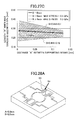
- FIG. 22 is a diagram showing the relationship between tilt angle sensitivity and maximum internal stress of the resonant drive part of each of the electrode arrangements of FIG. 21A , FIG. 21B , and FIG. 21C .
- FIG. 23A is a side view showing the resonant drive state of the actuator of Embodiment 1.
- FIG. 23B is a side view showing the resonant drive state of the actuator of Embodiment 2.
- FIG. 24A is a perspective view showing the composition of a front surface of an actuator of Embodiment 3 of the present disclosure.
- FIG. 24B is a perspective view showing the composition of a back surface of the actuator of Embodiment 3.
- FIG. 25A is a diagram for explaining the parameter setting of the actuator of Embodiment 3.
- FIG. 25B is a diagram for explaining the parameter setting of the actuator of Embodiment 3.
- FIG. 25C is a diagram for explaining the parameter setting of the actuator of Embodiment 3.
- FIG. 26A is a perspective view showing the composition of a front surface of an actuator of Embodiment 4 of the present disclosure.
- FIG. 26B is a perspective view showing the composition of a back surface of the actuator of Embodiment 4.
- FIG. 27A is a diagram for explaining an optimal design method for the actuator of Embodiment 4.
- FIG. 27B is a diagram for explaining the optimal design method for the actuator of Embodiment 4.
- FIG. 27C is a diagram for explaining the optimal design method for the actuator of Embodiment 4.
- FIG. 28A is a diagram for explaining the length B of a supporting beam side connection part which has the local minimum.
- FIG. 28B is a diagram for explaining the length B of the supporting beam side connection part which has the local minimum.
- FIG. 28C is a diagram for explaining the length B of the supporting beam side connection part which has the local minimum.
- FIG. 29 is a diagram for explaining the characteristics of tilt angle sensitivity of the actuator of Embodiment 4.
- FIG. 30 is a diagram showing the composition of a projector of Embodiment 5 of the present disclosure.
- FIG. 1 is a diagram showing the cross-sectional composition of an actuator of Embodiment 1 of the present disclosure.
- the actuator of Embodiment 1 includes a semiconductor wafer 10 and a drive source 20 .
- the actuator of Embodiment 1 may be produced by the fabrication processing of the semiconductor wafer 10 using the MEMS (Micro Electro Mechanical Systems) technology, for example.
- MEMS Micro Electro Mechanical Systems
- FIG. 1 the example at the time of constituting an actuator using such a semiconductor wafer 10 is illustrated.
- the semiconductor wafer 10 includes a silicon substrate 11 , a SiO 2 layer 12 , a SiO 2 layer 14 , and a Si activation layer 14 .
- a silicon-on-insulator (SOI) substrate may be used as the semiconductor wafer 10 .
- the SOT substrate is a substrate in which the SiO 2 layer 12 as the insulating layer is formed within the silicon substrate 11 .
- the SiO 2 layer is formed on the bottom of the silicon substrate at the etching end point when the silicon substrate 11 is removed by deep reactive ion etching etc., and the deep etching processing can be performed easily.
- a beam 15 is constituted by the SiO 2 layer 12 , the Si activation layer 13 , and the SIO 2 layer 14 .
- the beam 15 is used to perform a drive operation which supports an object to be driven and transmits a driving force to the object to be driven.
- the silicon substrate 11 is used as an outer fixed frame, for example.
- a total thickness of the semiconductor wafer 10 may be on the order of 300-500 ⁇ m.
- the beam 15 may have a total thickness of 31 ⁇ m, including 30 ⁇ m for the Si activation layer 13 and 0.5 ⁇ m for each of the SiO 2 layer 12 and the SiO 2 layer 14 , which is equal to about 1/10 thickness of the semiconductor wafer 10 .
- the drive source 20 is a source of power to generate a driving force in the actuator of this embodiment.
- various devices may be used as the drive source 20 .
- a piezoelectric device 21 is a passive element which converts the voltage supplied to a piezoelectric crystal 22 into the force.
- the piezoelectric device 21 in the actuator of this embodiment receives the voltage supplied, the length of the piezoelectric device 21 expands or contracts, thereby driving the beam 15 to which the piezoelectric device 21 is attached.
- Various piezoelectric crystals may be used as the piezoelectric crystal 22 .
- a PZT (titanic acid lead zirconate) thin film may be used as the piezoelectric crystal 22 .
- the piezoelectric device 21 may be formed to have a thickness on the order of 2 ⁇ m, for example, when the beam 15 has a thickness on the order of 30 ⁇ m.
- the piezoelectric device 21 includes an upper electrode 23 and a lower electrode 24 .
- the upper electrode 23 and the lower electrode 24 are electrodes for supplying the voltage to the piezoelectric crystal 22 , and the piezoelectric crystal 22 expands or contracts when the voltage is supplied to the upper electrode 23 and the lower electrode 24 , so that the beam 15 is caused to drive the object to be driven.
- FIGS. 2A-2C are diagrams for explaining a method of driving by the actuator of Embodiment 1 in which the piezoelectric device 21 causes the beam 15 to generate bending vibration.
- FIG. 2A is a side view showing the beam structure 15 of silicon and the piezoelectric device 21 .
- the piezoelectric device 21 is formed as a thin film on the beam 15 which includes the Si activation layer 13 .
- FIG. 2B is a diagram showing the state in which the piezoelectric device 21 contracts by elastic deformation.
- the beam structure 15 has an upwardly curved configuration that is convex in the downward direction.
- FIG. 2C is a diagram showing the state in which the piezoelectric device 21 expands by elastic deformation.
- the beam structure 15 has a downwardly curved configuration that is convex in the upward direction.
- the piezoelectric device 21 is curved upward or downward.
- an object may be driven by the piezoelectric device 21 as the drive source 20 in the actuator of this embodiment.
- FIG. 3 is a perspective view of a front surface of the actuator of Embodiment 1.
- an outer fixed frame of the actuator of this embodiment is formed by the silicon substrate 11 , and the portion inside the silicon substrate 11 is formed by a thin-film portion which has a thickness that is the same as a thickness of the beam 15 .
- the object 30 to be driven is arranged in the center of the actuator.
- a pair of drive sources 20 each of which is constituted by the piezoelectric device 21 , is formed on the beam 15 to sandwich the object 30 from both sides thereof, so that a pair of drive beams 70 is formed.
- the pair of drive sources 20 provided on the beam 15 to support the object 30 from both the sides thereof, forms the pair of drive beams 70 , and the object 30 is driven by the pair of drive beams 70 .
- the alternating voltage and the opposite alternating voltage are supplied to the piezoelectric devices 21 in the pair of drive beams 70 on the both sides of the object 30 respectively.
- the piezoelectric devices 21 By supplying such alternating voltage to the piezoelectric devices 21 , the displacements of the piezoelectric devices 21 in the different directions as shown in FIG. 2B and FIG. 2C take place, vibration occurs, and the object 30 is driven.
- the vibration generated by the piezoelectric device 21 which is the drive source 20 may be resonant vibration.
- the drive beam 70 is able to generate large bending vibration, and the object 30 can be driven greatly at a high speed.
- FIG. 4 is a perspective view showing the state in which the actuator of Embodiment 1 is driven.
- the object 30 is tilted around the axis of rotation X and vibrated through vibration which is generated by the drive beam 70 .
- the object 30 is tilted and vibrated such that the left-hand side of the object 30 is lowered and the right-hand side of the object 30 is lifted.
- the actuator of this embodiment is able to tilt and drives the object 30 around the axis of rotation.
- a mirror for use in a micro projector, a micro scanner, etc. may be used as the object 30 .
- a laser light beam is irradiated to a mirror and the light beam reflected from the mirror is scanned to draw an image.
- the horizontal scanning must be made at a high speed on the order of 30 kHz in the angle range of ⁇ 12 deg. and the vertical scanning must be made at a low speed on the order of 60 Hz in the angle range of ⁇ 18 deg.
- the high-speed tilting drive at frequencies on the order of 30 kHz is performed around the axis of rotation X.
- the resonant vibration may be used, and the high-speed tilting drive can be performed.
- FIG. 5 is a perspective view showing a drive source which performs a tilting drive of an object around two axes of rotation in the actuator of Embodiment 1. Since the actuator which performs the two-axis tilting drive is used in a micro projector or micro scanner in many cases, an example in which a mirror 31 is used as the object 30 will be described.
- a non-resonant drive source 90 which is a drive source for performing a low speed driving on the order of 60 Hz is additionally provided in the circumference of the mirror 31 .
- beams 15 are provided to extend in the directions perpendicular to the extending direction of the drive beam 70 , and the piezoelectric device 21 which is the drive source 20 is formed on the surface of each beam 15 .
- the non-resonant drive source 90 performs the tilting drive of the mirror 31 around the axis of rotation which is perpendicular to the axis of rotation X shown in FIG. 4 .
- the ends of the adjacent beams are connected so that the beam ends are arrayed alternately, and the non-resonant drive source 90 has a beam arrangement in a zigzag formation.
- the alternating positive/negative voltage is supplied to the drive sources 20 of the adjacent beams, and the operation in which the inclination in the extending direction of each beam is accumulated is performed, so that the tilting drive of the mirror 31 is performed in the extending direction of each beam 15 of the non-resonant drive source 90 .
- FIG. 6 is a perspective view showing the state where the non-resonant drive is performed by the non-resonant drive source 90 in the actuator of Embodiment 1.
- the tilt angle for each beam 15 of the non-resonant drive source 90 is accumulated and the tilting drive of the mirror 31 is performed around the axis of rotation Y.
- the tilting drive operation in which the right-hand side of the mirror is lowered and the left-hand side of the mirror is lifted is illustrated.
- the actuator of this embodiment can be used as a bi-axial drive actuator which combines the resonant drive part and the non-resonant drive part.
- FIG. 7 is a perspective view showing a resonant drive part 80 of the actuator of Embodiment 1.
- the resonant drive part 80 is constructed to include a mirror 31 , supporting beams 40 , connection parts 50 , movable frames 60 , drive beams 70 , and drive sources 20 , and these elements are connected together to form an integrated part.
- the mirror 31 is an object 30 to be driven for a tilting drive operation which is performed by the actuator of this embodiment.
- the object to be driven may be an object other than the mirror 31 .
- an example in which the object 30 to be driven is the mirror 31 will be described.
- the supporting beams 40 are a pair of beams which support the mirror 31 from both sides thereof.
- the pair of supporting beams 40 are provided on the right and left sides of the mirror 31 symmetrically around the axis of rotation X and connected to the mirror 31 .
- each supporting beam 40 is formed to include a thin silicon activation layer 14 having a thickness on the order of 30 ⁇ m, for example, and this supporting beam functions as an elastic member with elasticity.
- the movable frames 60 are a pair of media for transmitting bending vibration and a pair of movable supporting members which support the mirror 31 movably through the supporting beams 40 .
- the movable frames 60 are arranged symmetrically with respect to the axis of rotation X to sandwich the mirror 31 and the supporting beams 40 from both sides thereof.
- the mirror 31 and the supporting beams 40 are sandwiched from both the right-hand side and the left-hand side thereof by the movable frames 60 .
- the movable frames 60 as the whole have a rectangular shape.
- the movable frames 60 may have an arbitrary external shape if the movable frames 60 can support the supporting beams 40 and the mirror 31 from both the sides thereof so as to transmit bending vibration.
- the sides of the movable frames 60 are connected to the drive beams 70 each of which functions as a resonant vibration drive part, such that the drive beams 70 sandwich the movable frames 60 from both the sides thereof. Bending vibration from the drive beams 70 is transmitted to the movable frames 60 , and the movable frames 60 are a pair of media for transmitting the bending vibration.
- the drive beams 70 generate bending vibration as shown in FIGS. 2A-2C , 3 and 4 .
- the movable frames 60 are formed as a part of the thin-film Si activation layer 14 similar to the supporting beams 40 , function as a pair of elastic members with elasticity, and are able to transmit the bending vibration generated by the drive beams 70 .
- the movable frames 60 are connected to the supporting beams 40 via the connection parts 50 . Thereby, the movable frames 60 can transmit the vibration to the supporting beams 40 and support the supporting beams 40 .
- the movable frames 60 are connected to the drive beams 70 , but are not secured to a fixed body, such as the outer fixed frame. The movable frames 60 are held in a movable state and the movable frames 60 in the movable state transmit the vibration.
- connection parts 50 connect the movable frames 60 and the ends of the supporting beams 40 , convert the bending vibration from the movable frames 60 into torsional vibration, and transmit the torsional vibration to the supporting beams 40 .
- the connection parts 50 are arranged as the pair of connection parts to sandwich the supporting beams 40 from both the sides in the direction of the axis of rotation X.
- the movable frames 60 are arranged as the pair of movable frames to sandwich the supporting beams 40 from both the sides thereof in the direction perpendicular to the axis of rotation X, and each connection part 50 connects the three components: the supporting beam 40 and the movable frames 60 on the both sides of the supporting beam 40 .
- FIG. 8 is an enlarged view of the connection part 50 in the resonant drive part 80 of the actuator of Embodiment 1.
- the relationship between the mirror 31 , the supporting beam 40 , the movable frames 60 , and the drive beam 70 around the connection part 50 is illustrated.
- connection part 50 may be formed integrally with the supporting beam 40 and the movable frames 60 by using the same material as the supporting beam 40 and the movable frames 60 . Thereby, the resistance of the resonant drive part 80 can be increased, and the mechanical strength can be increased from that in a case in which two or more components are connected together.
- connection part 50 By forming the connection part 50 integrally with the supporting beam 40 and the movable frames 60 , the irregularities in transmitting the vibration can be reduced and the vibration can be smoothly transmitted.
- the connection part 50 may also be constructed by the SiO 2 layer 12 , the SiO 2 layer 14 , and the Si activation layer 13 of the semiconductor wafer 10 .
- connection part 50 may be constituted by a multiple beam structure including two or more slim beams which extend horizontally.
- the connection part 50 By forming the connection part 50 having such a beam structure, the elasticity of the connection part 50 can be increased from that in a case of a connection part having a large width, and the thus formed connection part 50 can convert the bending vibration transmitted from the movable frame 60 into the torsional vibration without causing stress concentrations on a particular portion thereof.
- connection part 50 As shown in FIG. 8 , an end portion of the supporting beam 40 opposite to the mirror 31 is connected to the connection part 50 .
- the torsional stress when performing the tilting drive of the mirror 31 is applied to this end portion and the maximum stress concentration arises at this end portion.
- the connection part 50 to which the end portion of the supporting beam 40 is connected is arranged to have a multiple beam structure, and not only the supporting beam 40 but also the connection part 50 can be subjected to torsional deformation according to the torsional stress on the supporting beam 40 , and the torsional stress on the supporting beam 40 can be distributed.
- connection part 50 may be formed to project outward. If the connection part 50 is formed to have a beam structure, the elasticity can be increased and the stress distribution can be promoted. Further, if the width of the supporting beams 40 is increased, the torsional stress on the supporting beams 40 can be reduced.
- the supporting beams 40 are formed to have a width larger than the width of the movable frames 60 in the direction of the axis of rotation X and the connection parts 50 are formed to have a beam structure projecting outward from the outside of the movable frames 60 according to the supporting beams 40 , an increased length of the beam which constitutes each connection part 50 can be taken, and the stress absorptive effect can be increased.
- connection parts 50 are formed to have a multiple beam structure that includes a first beam transversely extending from both the sides of the end portion of each supporting beam 40 in the direction perpendicular to the axis of rotation X and a second beam extending in the direction parallel to the axis of rotation X and connecting the end of the first beam and one of the movable frames 60 .
- this composition the length of the beam structure of each connection part 50 in the axial direction is increased and the stress distribution efficiency is increased.
- a corner 55 formed in a connecting area where the connection part 50 and the supporting beam 40 are connected together may be rounded off by machining. Thereby, the stress concentration in the connecting area between the supporting beam 40 and the connection part 50 can be reduced further.
- the machining to round off a corner 45 formed in the connecting area where the mirror 31 and the supporting beam 40 are connected together, a corner 65 formed in the connecting area where the connection part 50 and the movable frame 60 are connected together, and a corner 75 formed in the connecting area where the movable frame 60 and the drive beam 70 are connected together may be performed, and the stress concentration in these areas may be reduced further.
- the details of the machining to round off the corners 45 , 55 , 65 and 75 will be described later.
- each of the drive beams 70 is a driving force source which applies bending stress to the movable frame 60 .
- the drive beams 70 are arranged as a pair of drive beams so that the drive beams 70 extend in the directions perpendicular to the axis of rotation X and are connected to the movable frames 60 to sandwich the movable frames 60 from both the sides thereof.
- the drive source 20 is formed on the surface of the drive beam 70 , and the drive beam 70 itself is deformed by the drive source 20 and the drive beam 70 generates bending vibration.
- the piezoelectric device 21 may be used as the drive source 20 .
- any other device may be used if the device is able to generate bending vibration.
- the alternating positive/negative voltage and the opposite alternating positive/negative voltage are supplied to the piezoelectric devices 21 in the pair of drive beams 70 .
- the application of such alternating voltage may be performed from the upper electrode 23 and the lower electrode 24 provided on the piezoelectric crystal 22 as previously described with FIG. 1 .
- the drive beams 70 may be formed integrally with the movable frames 60 .
- the drive frames 70 may also be formed by the thin-film portion having the same thickness as the beam 15
- the resonant drive part 80 is constructed by the thin-film portion of the semiconductor wafer 10 having a thickness on the order of 30 ⁇ m, and this thin-film portion functions as an elastic member with elasticity.
- the thickness of the resonant drive part 80 is constant, and the elasticity thereof may be adjusted by changing the width, the length, the configuration, etc. of the resonant drive part 80 .
- the elasticity of the semiconductor wafer 10 may be adjusted by changing the configuration thereof, and the stress distribution efficiency may be increased. It is possible to provide an actuator which does not cause a problem, such as fracture by stress.
- FIG. 9 is a perspective view showing a deformed state of the resonant drive part 80 of the actuator of Embodiment 1 during a resonant drive vibration.
- the pair of drive sources 20 include a piezoelectric device 25 on the right-hand side and a piezoelectric device 26 on the left-hand side, and the alternating voltage and the opposite alternating voltage with different polarities or phases are supplied to the devices 25 and 26 respectively.
- the drive beam 71 on the right-hand side is curved upward and the drive beam 72 on the left-hand side is curved downward, and the drive beams 70 apply bending vibration to the movable frames 60 .
- the bending vibration in the movable frames 60 is transmitted to the supporting beams 40 via the connection parts 50 .
- the bending vibration is converted into torsional vibration, and the pair of supporting beams 40 are subjected to the torsional vibration around the axis of rotation X.
- the torsional vibration the mirror 31 which is supported from both the sides thereof by the supporting beams 40 is subjected to the tilting drive movement around the axis of rotation X. By this operation, the mirror 31 is tilted and driven around the axis of rotation X.
- FIG. 10 is an enlarged diagram showing a deformed state of the mirror 31 of the resonant drive part 80 of the actuator of Embodiment 1 during a resonant drive vibration.
- the mirror 31 is tilted and driven so that the right-hand side of the mirror 31 is lifted and the left-hand side of the mirror 31 is lowered.
- the movable frames 60 are also tilted in the same directions as the mirror 31 .
- the tilt angle of the mirror 31 in the tilted state is larger than that of the movable frames 60 .
- the alternating voltage and the opposite alternating voltage with different polarities or phases are supplied to the pair of drive sources 20 in the pair of drive beams 70 , the portion near the connecting area between the drive beam 70 and the movable frame 60 is greatly vibrated up and down by the resonant drive vibration.
- the movable frame 60 is inclined, the portion in the vicinity of the connection part 50 is inclined by the bending deformation of the movable frame 60 , and the connection part 50 is twisted, so that the mirror 31 is tilted.
- resonant vibration modes including a resonant vibration mode in which the mirror 31 and the movable frame 60 are inclined in the same direction as shown in FIG. 10 , and a resonant vibration mode in which the mirror 31 and the movable frame 60 are inclined in the mutually opposite directions.
- the actuator of this embodiment selects the resonant vibration mode in which the mirror 31 and the movable frame 60 are inclined in the same direction as shown in FIG. 10 .
- the displacement of the mirror 31 is added to the displacement of the movable frame 60 , and the tilt angle sensitivity of the mirror 31 to the supplied voltage can be increased.
- the connection part 50 is twisted, the amount of twisting relative to the tilt angle of the mirror 31 is very small. The internal stress can be made small, so that occurrence of fracture can be avoided.
- FIG. 11 is an enlarged diagram showing the mirror 31 , the supporting beams 40 and the connection parts 50 in the actuator of Embodiment 1 in the deformed state of FIG. 10 .
- the tilt angle of the mirror 31 can be secured by the twisting of the connection parts 50 .
- connection part 50 having the beam structure is provided in the area between the movable frame 60 and the supporting beam 40 to which large stress loads due to the conversion of bending stress into torsional stress are applied, and a sufficient tilt angle of the mirror 31 can be provided and the angle of twisting between the connection part 50 and the supporting beam 40 can be reduced.
- the actuator of this embodiment is activated to drive the mirror 31 at the frequency of about 30 kHz and with the tilt angle width of ⁇ 12 deg., the maximum internal stress in the connection parts 50 is below 0.4 GPa. This shows that the stress generated in the tilting drive state of the mirror 31 is distributed to the connection parts 50 , the movable frames 60 and the drive beams 70 .
- the resonance frequency can be adjusted by changing the width, the thickness, the cross-sectional shape, the length, etc. of the connection part 50 , and it is applicable to high speed tilting drive operations of 30 kHz or higher without changing the structure of the actuator.
- the shape of the connection part 50 is changed, the dimensions of the supporting beams 40 and the drive beams 70 may be changed accordingly.
- FIG. 12A and FIG. 12B are diagrams for explaining the composition of the actuator in which a rounded corner is formed in a connecting area 45 between the mirror 31 and the supporting beam 40 .
- FIG. 12A is a perspective view of the actuator in which a rounded corner is formed in the connecting area 45 between the mirror 31 and the supporting beam 40 .
- FIG. 12B is a diagram showing a change of the tilt angle sensitivity and a change of the maximum stress in the connecting area 45 at the tilt angles of ⁇ 12 deg. when the radius R of the rounded corner is changed.
- the mirror 31 has a circular shape and the supporting beam 40 has a rectangular shape, and if the rounding of the corner is not performed, the corner may have a sharp edge on the outside periphery of the connecting area 45 between the mirror 31 and the supporting beam 40 .
- a sharp edge may easily concentrate the internal stress on the corner.
- the internal stress can be distributed.
- the radius R of the rounded corner formed is in a range of 0.01-0.2 mm.
- the tilt angle sensitivity is not changed greatly, and it is slightly reduced when the radius R of the rounded corner is 0.01 mm or larger.
- the maximum internal stress of the rounded corner (the connecting area 45 ) is below 0.3 GPa, and this value is below 0.05 GPa that is indicated by the fracture stress value multiplied by the safety coefficient. It can be understood that there is no problem on the durability of the rounded corner.
- FIG. 13A and FIG. 13B are diagrams for explaining the composition of the actuator in which rounded corners are formed in the connecting area 45 between the mirror 31 and the supporting beam 40 , the connecting area 55 between the supporting beam 40 and the connection part 50 , and the connecting area 65 between the connection part 50 and the movable frame 60 .
- FIG. 13A is a perspective view of the actuator in which the rounded corners are formed in the connecting areas 45 , 55 and 65 .
- FIG. 13B is a diagram showing a change of the tilt angle sensitivity and a change of the maximum stress in the connecting areas 45 , 55 and 65 at the tilt angles of ⁇ 12 deg. when the radius R of the rounded corner is changed.
- the rounded corners are formed in the connecting area 45 between the mirror 31 and the supporting beam 40 , the connecting area 55 between the supporting beam 40 and the connection part 50 , and the connecting area 65 between the connection part 50 and the movable frame 60 .
- the radius R of each rounded corner in the connecting areas 55 and 65 may be in a range of 0.005-0.04 mm.
- FIG. 13B shows a change of the tilt angle sensitivity and a change the maximum stress in the composition which includes the rounded corners as shown in FIG. 13A .
- the tilt angle sensitivity is not changed greatly, but is slightly reduced when the radius R of the rounded corner is 0.02 mm or larger.
- the internal stress becomes the maximum in the connection part 50 where the torsion takes place.
- FIG. 14A and FIG. 14B are diagrams for explaining the composition of the actuator in which a rounded corner is formed in each of the connecting area 45 between the mirror 31 and the supporting beam 40 , the connecting area 55 between the supporting beam 40 and the connection part 50 , the connecting area 65 between the connection part 50 and the movable frame 60 , and the connecting area 75 between the movable frame 60 and the drive beam 70 .
- FIG. 14A is a perspective view of the actuator in which rounded corners are formed in the connecting areas 45 , 55 , 65 and 75 .
- FIG. 14B is a diagram showing a change of the tilt angle sensitivity and a change of the maximum stress of the connecting areas 45 , 55 , 65 and 75 at the tilt angles of ⁇ 12 deg. when the radius R of each rounded corner is changed.
- the rounded corner is formed also in the connecting area 75 between the movable frame 60 and the drive beam 70 , and the internal stress in the connecting area 75 can be distributed by performing the machining to form the rounded corner.
- the radius R of the rounded corner in the connecting area 75 is in a range of 0.005-0.06 mm.
- the maximum internal stress in the rounded corner whose radius R is in a range of 0.005-0.01 mm is on the order of 0.5 GPa. That is, in the actuator of this embodiment, there is a problem of fracture due to the influence of a damaged layer and the application of repeated stress by the deep reactive ion etching.
- FIGS. 15A-15C are diagrams showing the electrode arrangement of the drive sources 20 in the resonant drive part 80 .
- FIG. 15A is a diagram showing the composition of the resonant drive part 80 in which the drive sources 20 are provided only in the drive beams 70 .
- the resonant drive part 80 in which the drive sources 20 are provided only in drive beams 70 is shown.
- the up-and-down vibration of the drive beams 70 which include the pair of drive beams 71 and 72 is given to the movable frames 60 which include the pair of movable frames 61 and 62 as bending vibration.
- the bending vibration from the movable frames 60 is transmitted to the connection parts 50 , the bending vibration is converted into torsional vibration and the tilting drive operation of the supporting beams 40 and the mirror 31 is performed by the torsional vibration.
- FIG. 15B is a diagram showing the composition of the resonant vibration part 80 a in which the drive sources 20 a are provided on the drive beams 70 and the movable frames 60 .
- the drive sources 20 a are provided on the drive beams 70 and on the movable frames 60 .
- the drive sources 20 a include the pair of drive sources 25 and 26 provided on the pair of drive beams 71 and 72 respectively and the pair of drive sources 27 and 28 provided on the pair of movable frames 61 and 62 respectively.
- FIG. 15B is a diagram showing the composition of the resonant vibration part 80 a in which the drive sources 20 a are provided on the drive beams 70 and the movable frames 60 .
- the drive sources 20 a include the pair of drive sources 25 and 26 provided on the pair of drive beams 71 and 72 respectively and the pair of drive sources 27 and 28 provided on the pair of movable frames 61 and 62 respectively.
- FIG. 15B is a diagram showing the composition of the resonant vibration part 80
- the drive source 25 and the drive source 27 to which the voltage of the same polarity or same phase is supplied are provided on the drive beam 71 and the movable frame 61 on the right-hand side which are connected together
- the drive source 26 and the drive source 28 to which the voltage of the same polarity or same phase is supplied are provided on the drive beam 72 and the movable frame 62 on the left-hand side which are connected
- the polarity of the voltage supplied to the drive sources 26 and 28 is opposite to that supplied to the drive sources 25 and 27 .
- the drive sources 20 a are arranged so that the voltage of the same polarity may be supplied to the drive beams 70 and the movable beams 60 on the same side.
- FIG. 15C is a diagram showing the composition of a resonant vibration part 80 b in which drive sources 20 b are provided on the drive beams 70 and the movable frames 60 in a manner different from that in the case of FIG. 15B .
- the arrangement of the drive sources 20 b provided on the drive beams 70 is the same as that in the cases of FIGS. 15A and 15B , but the polarity of the voltage supplied to the drive sources 27 and 28 provided on the movable frames 60 is opposite to the polarity of the voltage supplied to the drive source 26 and the drive source 25 provided on the drive beams 70 .
- the polarity of the voltage supplied to the drive source 25 on the drive beam 71 on the right-hand side around the axis of rotation X, and the polarity of the voltage supplied to the drive source 28 on the movable frame 61 connected to the drive beam 71 are opposite to each other.
- the polarity of the voltage supplied to the drive source 26 on the drive beam 72 on the left-hand side, and the polarity of the voltage supplied to the drive source 27 on the movable frame 62 connected to the drive beam 72 are opposite to each other.
- the drive sources 25 and 26 on the pair of drive beams 71 and 72 are related to the mutually opposite polarities of the voltage supplied, and the drive sources 28 and 27 on the pair of movable frames 61 and 62 are related to the mutually opposite polarities of the voltage supplied.
- FIG. 16 is a diagram showing the relationship between the tilt angle sensitivity per unit voltage and the maximum internal stress of each of the three examples of the electrode arrangement of the resonant drive parts 80 , 80 a and 80 b shown in FIGS. 15A-15C .
- the tilt angle sensitivity per unit voltage will be compared between the examples.
- the composition of the actuator in which the drive sources 20 are provided only on the drive beams 70 as shown in FIG. 15A will be considered a standard composition.
- the tilt angle sensitivity decreases in the composition of FIG. 15B in which the drive sources 20 a on the drive beam 70 and the movable frame 60 on the same side are related to the same polarity of the voltage supplied, and the tilt angle sensitivity increases in the composition of FIG. 15C in which the drive sources 20 b on the drive beams 70 and the movable frames 60 on the same side are related to the mutually opposite polarities of the voltage supplied.
- the tilt angle sensitivity in the composition of FIG. 15A is 0.535 deg/V
- the tilt angle sensitivity in the composition of FIG. 15B is lowered to 0.131 deg/V
- the tilt angle sensitivity in the composition of FIG. 15C is lifted to 0.975 deg/V.
- the maximum internal stress will be compared between the examples of FIG. 15A , FIG. 15B and FIG. 15C .
- the composition of FIG. 15A will be considered a standard composition.
- the maximum internal stress in the composition of FIG. 15A is 0.39 GPa.
- the maximum internal stress in the composition of FIG. 15C is nearly equal to 0.40 GPa, and it can be understood that the composition of FIG. 15C shows a satisfactory value for eliminating the problem of fracture due to the stresses.
- the maximum internal stress in the composition of FIG. 15B increases to 0.59 GPa, this maximum internal stress exceeds 0.5 GPa, and the problem of fracture due to the stresses may arise.
- the actuator having the composition of FIG. 15C has the highest value of the tilt angle sensitivity and does not have a problem on the maximum internal stress. Therefore, the composition of FIG. 15C in which the drive sources 20 b are provided on both the drive beam 70 and the movable frame 60 such that the polarities of the voltage supplied to the drive sources 20 b on the drive beam 70 and the movable frame 60 which are connected together are opposite to each other, is the most efficient and does not cause the problem of fracture by the stresses.
- the tilt angle sensitivity can be improved without changing the outside dimensions.
- the tilt angle sensitivity is increased 1.8 times and the supplied voltage can be reduced to 1/1.8.
- the drive voltage required for the tilt angle range of ⁇ 12 deg. of the mirror 31 is in a range of 0-22.5 V in the composition of FIG. 15A , and the required drive voltage in the composition of FIG. 15C can be reduced to a range of 0-12.5 V.
- the tilt angle sensitivity can be increased. Because the directions of elastic deformation of the piezoelectric devices in the drive sources related to the opposite polarities of the supplied voltage are opposite to each other, a large bending vibration can be generated.
- the connection part 50 is provided to link the movable frame 60 connected to the drive beam 70 having the drive source 20 provided thereon, to the supporting beam 40 connected to the mirror 31 .
- the connection part 50 By using the connection part 50 , the bending vibration can be converted into the torsional vibration without increasing the internal stresses, and the tilting drive operation of the mirror 31 can be performed.
- the machining to form the rounded corners in the connecting areas 45 , 55 , 65 and 75 may be performed.
- the drive sources 20 b may be provided on the drive beam 70 and the movable frame 60 .
- the polarities of the voltage supplied to the drive sources 20 b on the drive beam 70 and the movable frame 60 connected together may be opposite to each other. According to the actuator of Embodiment 1, the tilt angle sensitivity can be improved and the internal stress distribution effect can be acquired.
- FIG. 17 is a perspective view showing the composition of a resonant drive part 81 of an actuator of Embodiment 2 of the present disclosure.
- the resonant drive part 81 of the actuator of Embodiment 2 includes a mirror 31 , supporting beams 40 a , connection parts 50 a , movable frames 60 , drive beams 70 , and drive sources 20 .
- the actuator of Embodiment 2 has the same composition as the actuator of Embodiment 1 except for the cross-sectional configuration and the composition of the resonant drive part 81 , such as a non-resonant drive part, and a description thereof will be omitted.
- the elements in Embodiment 2 which are the same as corresponding elements in Embodiment 1 are designated by the same reference numerals, and a description thereof will be omitted or simplified.
- the pair of supporting beams 40 a are arranged to support the mirror 31 from both sides thereof, and each of the pair of connection parts 50 a connects one of the pair of movable frames 60 (which include movable frames 61 and 62 ) and one of the pair of supporting beams 40 a .
- the basic composition of the actuator of Embodiment 2 in which the pair of drive beams 70 (which include drive beams 71 and 72 ) are connected to the both sides of the movable frames 60 in the direction perpendicular to the axis of rotation X and the pair of drive sources 20 (which include drive sources 25 and 26 ) are provided on the drive beams 71 and 72 is essentially the same as that of the actuator of Embodiment 1. Also, operation of the actuator of Embodiment 2 is essentially the same as that of the actuator of Embodiment 1 in that bending vibration on the drive beams 70 generated by the drive sources 20 is converted into torsional vibration by the connection parts 50 a and a tilting drive operation of the mirror 31 is performed through the supporting beams 40 a.
- the actuator of Embodiment 2 differs from the actuator of Embodiment 1 in that each of the supporting beams 40 a on the both sides of the mirror 31 is divided along the direction parallel to the axis of rotation X into two supporting beam portions.
- the actuator of Embodiment 2 differs from the actuator of Embodiment 1 in that because one of the supporting beams 40 a on one side of the mirror 31 includes two supporting beam portions, each of the connection parts 50 a on one side of the mirror 31 is arranged to connect one of the two supporting beam portions of the supporting beam 40 a to one of the movable frames 61 and 62 which is nearer to the connection part 50 a.
- FIG. 18 is an enlarged perspective view showing the supporting beam 40 a , the connection part 50 a , and the movable frames 60 in the actuator of Embodiment 2.
- each supporting beam 40 on one side in the actuator of Embodiment 1 is one
- the central part of each supporting beam 40 a in the actuator of Embodiment 2 in FIG. 18 is arranged to have a recessed configuration along the axis of rotation X.
- the width of each supporting beam 40 a is made small and the supporting beam 40 a includes two slim beam portions having a width smaller than that of the supporting beam 40 of Embodiment 1.
- connection part 50 a transversely extends from both sides in the direction perpendicular to the axis of rotation X and is connected to the movable beam 60 along the axis of rotation X.
- the connection part 50 a has a multiple beam structure and the configuration of the connection part 50 a itself remains unchanged.
- the connection part 50 a is formed to include a connection part 51 corresponding to the beam portion 41 and a connection part 52 corresponding to the beam portion 42 , so that the connection parts 51 and 52 of the connection part 50 a correspond to the beam portions 41 and 42 of the connection part 50 a respectively.
- the actuator of Embodiment 2 it is possible to provide the portion of the beam structure of each connection part 50 a which is longer than that in the actuator of Embodiment 1, and it is possible to perform the operation on the connection part 51 and the operation on the connection part 52 in a different manner.
- the flexibility of deformation of the connection parts 50 a can be increased and the bending vibration transmitted from the movable frames 60 can be converted into torsional vibration more efficiently.
- FIG. 19 is a diagram showing a deformed state of a resonant drive part 81 of the actuator of Embodiment 2 during a resonant drive vibration.
- the alternating voltage and the opposite alternating voltage with different polarities are supplied to the drive source 25 and the drive source 26 , the drive beam 71 is curved upward, and the drive beam 72 is curved downward so that bending vibration is applied to the pair of the movable frames 61 and 62 .
- the bending vibration applied to the movable frames 61 and 62 is transmitted to the connection parts 50 a , the bending vibration is converted into torsional vibration and transmitted to the supporting beams 40 a .
- the bending vibration of the movable frame 61 is transmitted to the connection part 51 and the bending vibration of the movable frame 62 is transmitted to the connection part 52 , which is differs from the actuator of Embodiment 1.
- the torsional vibration from the connection part 51 is transmitted to the supporting beam 41 and the torsional vibration from the connection part 52 is transmitted to the connection part 52 .
- the right-hand side supporting beam 40 a but also the left-hand side supporting beam 40 a performs the same operation, and the tilting drive operation of the mirror 31 is performed.
- FIG. 20 is an enlarged perspective view showing a deformed state of the resonant drive part 81 of the actuator of Embodiment 2 during a resonant drive vibration.
- the deflection of the movable frames 61 and 62 by the bending vibration transmitted from the drive beams 71 and 72 is transmitted to the connection part 50 a , and, in the connection part 50 a , a level difference between the upper connection part 51 and the lower connection part 52 is produced. Because of the level difference in the connection part 50 a , a level difference between the upper supporting beam 41 and the lower supporting beam 42 in the supporting beam 40 a is also produced. If the level difference is increased, the tilt angle of the mirror 31 can be increased.
- the supporting beam 40 a By arranging the supporting beam 40 a to have the two beam portions, a level difference between the beam portions 41 and 42 can be formed when the beam portions 41 and 42 are twisted, and the tilt angle of the mirror 31 can be increased.
- the movable frame 60 and the mirror 31 are inclined in the same direction in FIG. 20 . Also in the actuator of Embodiment 2, by using the resonance mode in which the mirror 31 and the movable frame 60 are inclined in the same direction, the displacement of the movable frame 60 is added to the displacement of the mirror 31 in the resonance mode, and the tilt angle sensitivity of the mirror 31 can be increased.
- both the supporting beam 40 a and the connection part 50 a are twisted and both the drive beam 70 and the movable frame 60 are deformed, the amount of the torsional deformation is small relative to the value of the tilt angle, and it is possible to provide the actuator in which the internal stress is small and fracture does not easily takes place.
- the actuator of this embodiment can set the mirror tilt angle sensitivity to 0.56 deg/V and can set the maximum internal stress to 0.48 GPa.
- the resonance frequency can be adjusted by changing the width, the thickness, the cross-sectional shape, the length, etc. of both or either of the supporting beam 40 a and the connection part 50 a , and it is applicable to high speed tilting drive operations of 30 kHz or higher without changing the structure of the actuator.
- the shape of the supporting beam 40 a and/or the connection part 50 a is changed, the dimensions of the movable frames 60 and the drive beams 70 may be changed accordingly.
- FIGS. 21A-21C are diagrams showing an example of the electrode arrangement of the resonant drive part 81 of the actuator of Embodiment 2.
- FIG. 21A is a perspective view of the resonant drive part 81 , as shown in FIGS. 17-20 , in which the drive sources 20 are provided only on the drive beams 70 .
- FIG. 21B is a perspective view of a resonant drive part 81 a in which drive sources 20 a of the same polarity are provided on the drive beam 70 and the movable frame 60 .
- FIG. 21C is a perspective view of a resonant drive part 81 b in which drive sources 20 a of different polarities are provided on the drive beam 70 and the movable frame 60 .
- FIG. 21A The composition of FIG. 21A is the same as the composition of FIGS. 17-20 , the elements in FIG. 21A which the same as corresponding elements in FIGS. 17-20 are designated by the same reference numerals, and a description thereof will be omitted.
- the composition of FIG. 21B differs from that of FIG. 21A in that drive sources 27 and 28 are additionally provided on the drive beam 70 and the movable frame 60 .
- the voltage of the first polarity is supplied from the drive sources 25 and 27 to the drive frame 71 and the movable frame 61 connected to the drive beam 71 .
- the voltage of the second polarity opposite to the first polarity is supplied from the drive sources 26 and 28 to the drive frame 72 and the movable frame 62 connected to the drive beam 72 .
- the same polarity voltage is supplied to the drive source 25 and the drive source 27 and the same polarity voltage is supplied to the drive source 26 and the drive source 28 , but the polarity of the voltage supplied to the drive sources 25 and 27 is opposite to the polarity of the voltage supplied to the drive sources 26 and 28 .
- This method of supplying the voltage is the same as that in the actuator of Embodiment 1 as shown in FIG. 15B .
- the composition of FIG. 21C is similar to the composition of FIG. 21B in that the drive sources 27 and 28 are provided on the drive beam 70 and the movable frame 60 .
- the composition of FIG. 21C differs from the composition of FIG. 21B in that the polarity of the voltage supplied to the drive source 28 on the movable frame 61 connected to the drive beam 71 is opposite to the polarity of the voltage supplied to the drive source 25 on the drive beam 71 , and the polarity of the voltage supplied to the drive source 27 on the movable frame 62 connected to the drive beam 72 is opposite to polarity of the voltage supplied to the drive source 26 on the drive beam 72 .
- This method of supplying the voltage is the same as that in the actuator of Embodiment 1 as shown in FIG. 15C .
- FIG. 22 is a diagram showing the relationship between tilt angle sensitivity and maximum internal stress of the resonant drive part of each of the electrode arrangements of FIG. 21A , FIG. 21B and FIG. 21C .
- the highest tilt angle sensitivity is provided by the actuator which has the resonant drive part 81 a of the composition of FIG. 21B .
- the resonant drive part 81 of the composition of FIG. 21A and the resonant drive part 81 a of the composition of FIG. 21B equally show the smallest value of the maximum internal stress.
- the electrode arrangement, as shown in FIG. 21B in which the voltage of the same polarity is supplied to the movable frame 60 connected to the drive beam 70 is the optimal for performing the resonant drive operation. This result differs from that of the actuators of Embodiment 1.
- FIGS. 23A and 23B are diagrams for explaining the optimal electrode arrangement of the actuator of Embodiment 1 which differs from the optimal electrode arrangement of the actuator of Embodiment 2.
- FIG. 23A is a side view showing the deformed state at the time of the resonant drive state of the actuator of Embodiment 1
- FIG. 23B is a side view showing the deformed state at the time of the resonant drive state of the actuator of Embodiment 2.
- the movable frame 60 is displaced up and down to drive beam 70 and an opposite direction in the actuator of Embodiment 1, main beam 40 and connection part 50 incline, and the amount of the angle of rotation of the mirror 31 is increased.
- the main beam 40 and the connection part 50 incline, and the tilt angle of the mirror 31 becomes large, so that the camber condition of the movable frame 61 and drive beam 71 and the camber condition of the movable frame 62 and drive beam 72 are large.
- the movable frame 60 and drive beam 70 are displaced like one spring and main beam 40 is displaced up and down in the actuator of Embodiment 2, the amount of the angle of rotation of the mirror 31 is increased.
- the supporting beam 41 and the supporting beam 42 open perpendicularly, a level difference becomes large, and the tilt angle of the mirror 31 is increased, so that the difference of lifting displacement of the movable frame 61 and drive beam 71 and lowering displacement of the movable frame 62 and drive beam 72 is large. It can be understood that the mechanisms to which the same frequency and the same resonance mode also incline completely differ by whether two it is whether the number of supporting beams 40 and 40 a is one.
- Embodiment 2 the machining to form the rounded corners has not been described, but also in Embodiment 2, the machining to form the rounded corners is applicable.
- the detailed composition thereof may be the same as that of Embodiment 1.
- FIGS. 24A and 24B are perspective views showing the composition of an actuator of Embodiment 3 of the present disclosure.
- FIG. 24A is a perspective view of the front surface of the actuator of Embodiment 3
- FIG. 24B is a perspective view of the back surface of the actuator of Embodiment 3.
- the actuator of Embodiment 3 includes a movable part 100 and a fixed frame 110 .
- the fixed frame 100 is an outer frame which is in a fixed state during the drive operation, and connection support of the movable part 110 is performed at the fixed frame 100 .
- the movable part 100 has object 30 , one pair of supporting beams 40 b , one pair of connection parts 50 b , and one pair of drive beams 73 .
- connection part 50 b include a drive beam side connection part 53 connected to the drive beam 73 , and a supporting beam side connection part 54 which connects the supporting beam 40 b to the drive beam side connection part 53 .
- Each of the surface sides of the actuator of Embodiment 3 includes the Si activation layer 13 .
- the point that supporting beam 40 which extends along a shaft direction in object 30 is connected is the same as that of the actuator of Embodiment 1.
- the actuator of Embodiment 3 differs from the actuator of Embodiment 1 or Embodiment 2 in that the movable frame 60 is not formed. In the actuator of Embodiment 3, it extends for a long time in the direction perpendicular to the axis of rotation X, and the supporting beam side connection part 54 of the connection part 50 b is comparable as the width of the object 30 .
- connection part 50 b is constituted to include the supporting beam side connection part 54 which connects the drive source side connection part 53 directly connected to the drive beam 73 instead of the movable frame 60 , the drive beam side connection part 53 , and the supporting beam 40 b.
- the position where supporting beam side connection part 54 and drive beam side connection part 53 are connected is the same as the end of object 30 , or may be constituted outside it.
- the length of the drive beam side connection part 53 prolonged in the object 30 side in parallel to the axis of rotation X can be secured long enough, and it becomes possible to fully perform absorption abatement of stress.
- drive beam side connection part 53 has beam structure which reduces stress while being able to transmit the tilting force of drive beam 73 to the supporting beam side connection part 54 , it can perform stress distribution appropriately.
- a smaller space-saving actuator can be constituted by excluding the movable frame 60 .
- the drive beam 73 enlarges width parallel to the axis of rotation X, and enlarges the film formation area of piezoelectric device 21 which is the drive source 20 .
- the drive beams 73 are the both sides in the axis of rotation X, and the alternating voltages with different polarities are supplied thereto, which is the same as in the actuator of Embodiment 1 or Embodiment 2.
- the mono-axial drive type actuator with which the actuator of Embodiment 3 performs tilting movement around the axis of rotation X is shown.
- the actuator of Embodiment 3 can be constituted as a 1 shaft side actuator.
- the actuator which performs a tilting drive is arranged around the axis of rotation different from the axis of rotation X, and it is good for the domain of fixed frame 110 also as a two axes type actuator.
- the actuator of Embodiment 3 is applicable also to a mono-axial drive type actuator and a bi-axial drive type actuator.
- FIG. 24B although the rear-face composition of the actuator of Embodiment 3 is shown, the movable part 100 which showed in FIG. 24A is formed to having a small thickness as the beam 15 , and the fixed frame 110 includes the silicon substrate 11 having a small thickness.
- FIGS. 25A-25C are diagrams for explaining the parameter setting which improves the tilt angle sensitivity of the actuator of Embodiment 3 and reduces the maximum stress thereof.
- FIG. 25A is a diagram showing the flat-surface composition of the movable part 100 of the actuator of Embodiment 3.
- the axis of rotation Y which is perpendicular to the axis of rotation X and passes along the center of the object 30 is illustrated.
- width of supporting beam 40 b is set to A
- the width of drive beam side connection part 53 is set to one half A/2 of the width A of the supporting beam 40 b .
- the distance from the outer end B, the supporting beam 40 b , and the drive beam side connection part 53 to the axis of rotation Y is set to C for the length of the supporting beam side connection part 54 .
- the resonance frequency is fixed to 30 kHz by making the variable distance C from the outside end of the supporting beam 40 b and the drive beam side connection part 53 in the direction of the axis of rotation Y.
- four drive beam side connection parts 53 exist, they are altogether set as a common value.
- the width A of the supporting beam 40 b and the length B of supporting beam side connection part 54 are modified as parameters, and the tilt angle sensitivity and the optimum value of the maximum stress are examined.
- FIG. 25B is a diagram showing the change characteristic of the tilt angle sensitivity deg/V to the change of the width A of the supporting beam 40 b in the case of making object 30 tilt by the tilt angle of ⁇ 12 deg, and the length B of the supporting beam side connection part 54 .
- the voltage for making the tilt angle sensitivity tilt by the tilt angle of 4.50 deg/V and ⁇ 12 deg. can be set to 0-5.3 V, the maximum stress can be set to 0.38 GPa, and it can be considered as the good characteristics that the maximum stress is small and the tilt angle sensitivity is high.
- FIG. 26A and FIG. 26B are perspective views showing the composition of an actuator of Embodiment 4 of the present disclosure.
- FIG. 26A is a diagram showing the composition of a front surface of the actuator of Embodiment 4
- FIG. 26B is a diagram showing the composition of a back surface of the actuator of Embodiment 4.
- the actuator of Embodiment 4 includes a movable part 101 and a fixed frame 111 .
- the fixed frame 111 of the point that are an outer frame in a fixed state and connection support of the movable part 111 is performed also during the drive operation at the fixed frame 111 is the same as that of the actuator of Embodiment 3.
- the movable part 101 includes an object 30 , a pair of supporting beams 40 c , a pair of connection parts 50 c , and connection part 50 c of it is the same as that of the actuator which the point containing drive beam side connection part 53 and supporting beam side connection part 54 also requires for Embodiment 3.
- the supporting beam 40 c has separated along the direction parallel to the axis of rotation X, and the actuator of Embodiment 4 differs from the actuator of Embodiment 3 at the point which has become two.
- the composition of this supporting beam 40 c is supporting beam 40 a of the actuator of Embodiment 2, and similar composition.
- connection part 50 c also contains two connection parts 50 c .
- Each is vertically prolonged in the direction of the axis of rotation X, and two connection parts 50 c serve as the form where each formed U character with supporting beam 40 c.
- the actuator of Embodiment 4 has composition which can obtain a large tilt angle by enlarging the difference of elevation of the two supporting beams 40 c , and driving it like the actuator of Embodiment 2.
- the length of the supporting beam side connection part 54 which extends in the direction perpendicular to the axis of rotation X of the connection part 50 c is comparable as the width of object 30 , or is more than it, and the point which does not need the movable frame 60 is the same as that of the actuator of Embodiment 3.
- the movable frame 60 is not needed but a small space-saving actuator can be provided.
- connection part 50 c can absorb and reduce the added stress, can be stabilized, and can carry out tilting movement of the object 30 .
- the features that the area of the drive beam 73 on which the drive source 20 is formed can be increased and sufficient tilt angle sensitivity and high speed drive can be realized are the same as that of the actuator of Embodiment 3.
- FIG. 26B the perspective view of the back surface of the actuator of Embodiment 4 is given.
- the outer fixed frame 111 includes a thick silicon substrate 11 , and the point of the movable part 101 which includes a thin elastic body as the beam 15 is the same as that of the actuator of Embodiment 3.
- FIGS. 27A-27C are diagrams for explaining the optimal design method for the movable part 101 of the actuator of Embodiment 4.
- FIG. 27A is a diagram showing the composition of the actuator of Embodiment 4.
- the supporting beam 40 c in the actuator of Embodiment 4 includes two supporting beams 41 a and 42 a separated along the direction parallel to the axis of rotation X.
- the connection part 50 c is also divided into two connection parts 51 a and 52 a which are separated from each other symmetrically with respect to the axis of rotation X.
- the connection part 51 a is connected to the supporting beam 41 a
- the connection part 52 a is connected to the supporting beam 42 a .
- connection parts 51 a and 52 a transversely extends in the direction perpendicular to the axis of rotation X apart from the axis of rotation X and the drive source side connection part 53 extends in the direction parallel to the axis of rotation X.
- each parameter is defined as follows.
- Each width of the beams 41 a and 42 a of the supporting beam 40 c is 0.06 mm, and similarly the width of the drive beam side connection part 53 of the connection part 50 c is 0.06 mm.
- the resonance frequency can be greatly adjusted by changing the width of the supporting beam 40 c which elastically supports the object 30 and the width of the drive beam side connection part 53 . It is supposed that, in this embodiment, the widths of the supporting beam 40 c and the drive beam side connection part 53 are set to be constant, and other parameters are varied.
- the distance between the two supporting beams 41 a and 42 a is set to A, and the length of supporting beam side connection part 54 is set to B.
- the resonance frequency can be adjusted to a fixed level of 30 kHz by making the parameter C variable. That is, fine adjustment of the resonance frequency is attained.
- FIG. 27B is a diagram showing the change characteristic of the maximum stress when the ⁇ 12 deg tilting drive operation of the object 30 is performed under the conditions of FIG. 27A , with the distance A between the two supporting beams 41 a and 42 a , and the distance B between the supporting beam 40 c and the drive beam side connection part 53 (the length of the supporting beam side connection part 54 ) being made the variables.
- the horizontal axis denotes the length B of the supporting beam side connection part 54 in mm
- the vertical axis denotes the maximum stress in GPa.
- the above formula (1) is a relational expression obtained by connecting the local minimum of each characteristic curve.
- FIGS. 28A-28C are diagrams for explaining the length B of the supporting beam side connection part 54 which has the local minimum.
- the stress is concentrated on the drive beam side connection part 53 as indicated by the arrow Sc in FIG. 28A .
- the stress is concentrated on the supporting beam 40 c as indicated by the arrow Sc in FIG. 28B .
- the stress is concentrated on the position of the connection part 50 c in the vicinity of an intermediate position between the supporting beam 40 c and the drive beam side connection part 53 as indicated by the arrow Sc in FIG. 28C .
- the width of each of the supporting beam 40 c and the drive beam side connection part 53 is 0.06 mm, which is smaller than the width of the supporting beam side connection part 50 c which connects these parts, and contains the torsion part. Therefore, if the length of the supporting beam side connection part 54 is too small, the stress will be concentrated on the torsion part of the drive beam side connection part 53 , and if the length of the supporting beam side connection part 54 is too large, the stress will be concentrated on the torsion part of the supporting beam 40 c .
- stress raisers can be shifted to the supporting beam side connection part 54 .
- the stress when the ⁇ 12 deg tilting drive operation of the object 30 is performed can be reduced and the local minimum can be given.
- the distance B where the stress is below the threshold value of 0.5 GPa satisfies the conditions of the following formula (4).
- FIG. 27C is a diagram showing the ranges in which the relational expressions of the above formulas (1)-(4) are met.
- the horizontal axis denotes the distance A between the supporting beams 41 a and 42 a in mm
- the vertical axis denotes the length B of the supporting beam side connection part 54 in mm.
- the range which satisfies the formula (4) is indicated by the shaded lines, and the condition of the formula (1) is included between the borderlines represented by the formula (2) and the formula (3).
- the combination of the values of A and B which satisfy the condition of the formula (1) is the optimal.
- the values of A and B fall within the range of the formula (4), it can be said that there is no design problem. Therefore, it can be understood that it is sufficient to obtain the design in which the distance A between the supporting beams 41 a and 42 a and the length B of the supporting beam side connection part 54 are defined by the values which fall within the range of the formula (4) indicated by the shaded lines in FIG. 27C .
- FIG. 29 is a diagram showing the characteristics of the tilt angle sensitivity when the distance A between the supporting beams 41 a and 42 a and the length B of the supporting beam side connection part 54 are set to the parameters.
- the horizontal axis denotes the length B of the supporting beam side connection part 54 in mm
- the vertical axis denotes the tilt angle sensitivity in deg/V.
- the characteristics in this case are such that the tilt angle sensitivity is 3.58 deg/V, the voltage needed to obtain the tilt angles of ⁇ 12 deg. is set to 0-6.5 V, and the maximum stress is 0.49 GPa.
- the tilt angle sensitivity in the actuator of Embodiment 4 is lower than that in the actuator of Embodiment 3, and the maximum stress in the actuator of Embodiment 4 is larger than that in the actuator of Embodiment 3.
- the actuator of Embodiment 4 can be formed smaller in size than the actuator of Embodiment 3. Therefore, when it is desired to use an actuator with higher tilt angle sensitivity, the actuator of Embodiment 3 may be selected, and when it is desired to use a smaller actuator, the actuator of Embodiment 4 may be selected. In this manner, one of the actuator of Embodiment 3 and the actuator of Embodiment 4 can be properly selected depending on the usage.
- the object to be driven by the actuator of Embodiment 3 or Embodiment 4 may be the mirror 31 as previously explained in Embodiment 1 or Embodiment 2.
- Embodiment 3 or Embodiment 4 the example of the mono-axial drive actuator has been described.
- a bi-axial drive actuator may be constituted by the actuator of Embodiment 3 or 4.
- FIG. 30 is a diagram showing the composition of a projector 200 of Embodiment 5 of the present disclosure.
- Embodiment 5 an example in which the actuator of any of Embodiments 1-4 is applied to an optical scanning device 200 , namely the projector 200 , will be described.
- the projector 200 of Embodiment 5 includes a first piezoelectric mirror 120 , a second piezoelectric mirror 121 , a laser diode 130 , a collimating lens 140 , a CPU (central processing unit) 150 , a laser diode driver IC (integrated circuit) 160 , a first piezoelectric mirror driver IC 170 , and a second piezoelectric mirror driver IC 171 .
- a screen 210 is illustrated as a related component.
- the projector 200 is an optical scanning device which projects an image on the screen 210 .
- the first piezoelectric mirror 120 is constituted as a mono-axial drive actuator which tilts and drives the mirror 31 around the axis of rotation X and applied to the projector 200 .
- the second piezoelectric mirror 120 is constituted as a mono-axial drive actuator which tilts and drives the mirror 31 around the axis of rotation Y and applied to the projector 200 .
- the laser diode 130 is a light source which emits a laser beam.
- the laser beam emitted from the laser diode 130 may be a diverging light beam.
- the collimating lens 140 is a unit to convert the diverging light beam into a parallel light beam.
- the parallel light beam may include a P polarized light beam in which the light beam vibrates in the directions within the plane of incidence of the light beam, and an S polarized light beam in which the light beam vibrates in the directions at right angles to the plane of incidence of the light beam.
- the parallel light beam from the collimating lens 220 is irradiated to the first piezoelectric mirror 120 , and reflected by the mirror 31 .
- the first piezoelectric mirror 120 performs the tilting drive of the mirror 31 around the axis of rotation X and provides the motion in which the reflected laser beam vibrates at right angles to the axis of rotation X.
- the first piezoelectric mirror 120 may be constituted by any of the actuators of Embodiments 1-4.
- the reflected light beam from the first piezoelectric mirror 120 is irradiated to the second piezoelectric mirror 121 .
- the second piezoelectric mirror 121 performs the tilting drive of the mirror 31 around the axis of rotation Y and reflects the laser beam sent from the first piezoelectric mirror 120 . Thereby, the motion in which the reflected light beam vibrates at right angles to the axis of rotation Y is provided.
- the second piezoelectric mirror 121 is constituted by any of the actuators of Embodiments 1-4, similar to the first piezoelectric mirror 120 .
- the laser beam reflected by the second piezoelectric mirror 121 is irradiated to the screen 210 .
- the laser beam on the screen 210 can be scanned in the mutually orthogonal directions to form an image.
- the CPU 150 is a unit to control the laser diode driver IC 160 , the first piezoelectric mirror driver IC 170 , and the second piezoelectric mirror driver IC 171 .
- the laser diode driver IC 160 is a unit to drive the laser diode 130 .
- the first piezoelectric mirror driver IC 170 is a unit to drive the first piezoelectric mirror 120
- the second piezoelectric mirror driver IC 171 is a unit to drive the second piezoelectric mirror 121 .
- the CPU 150 controls the laser driver IC 160 to drive the laser diode 130 .
- the CPU 150 controls the second piezoelectric mirror driver 171 , and controls tilting operation around the axis of rotation Y of the second piezoelectric mirror 121 while it controls the first piezoelectric mirror driver 170 and controls tilting operation around the axis of rotation X of the first piezoelectric mirror 120 .
- the bi-axial motion around the axis of rotation X and the axis of rotation Y is provided to the laser beam, and the light beam reflected by the mirror 31 of the second piezoelectric mirror 121 is scanned over the screen 210 so that an image is formed on the screen 210 .
- the actuator of this embodiment can be suitably applied to the piezoelectric mirrors 120 and 121 in the projector 200 .
- the stress loads can be reduced, and the mirror 31 can be driven in a stable state to project an image on the screen.
- Embodiment 5 the example in which the first piezoelectric mirror 120 performs the tilting drive operation around the axis of rotation X and the second piezoelectric mirror 121 performs the tilting drive operation around the axis of rotation Y has been illustrated.
- the present embodiment may be modified such that the sequence of the operations is reversed.
- the second axis of rotation around which the tilting drive operation is performed by the second piezoelectric mirror 121 may be optional depending on the usage if the axes of rotation differ from each other.
Landscapes
- Physics & Mathematics (AREA)
- General Physics & Mathematics (AREA)
- Optics & Photonics (AREA)
- Micromachines (AREA)
- General Electrical Machinery Utilizing Piezoelectricity, Electrostriction Or Magnetostriction (AREA)
- Mechanical Light Control Or Optical Switches (AREA)
- Mechanical Optical Scanning Systems (AREA)
- Facsimile Scanning Arrangements (AREA)
Applications Claiming Priority (5)
| Application Number | Priority Date | Filing Date | Title |
|---|---|---|---|
| JP2009114317 | 2009-05-11 | ||
| JP2009-114317 | 2009-05-11 | ||
| JP2009205316A JP5444968B2 (ja) | 2009-05-11 | 2009-09-04 | アクチュエータ及びこれを用いた光走査装置 |
| JP2009-205316 | 2009-09-04 | ||
| PCT/JP2010/057096 WO2010131557A1 (ja) | 2009-05-11 | 2010-04-21 | アクチュエータ及びアクチュエータを用いた光走査装置 |
Related Parent Applications (1)
| Application Number | Title | Priority Date | Filing Date |
|---|---|---|---|
| PCT/JP2010/057096 A-371-Of-International WO2010131557A1 (ja) | 2009-05-11 | 2010-04-21 | アクチュエータ及びアクチュエータを用いた光走査装置 |
Related Child Applications (1)
| Application Number | Title | Priority Date | Filing Date |
|---|---|---|---|
| US14/031,162 Division US8681404B2 (en) | 2009-05-11 | 2013-09-19 | Actuator and optical scanning device using actuator |
Publications (2)
| Publication Number | Publication Date |
|---|---|
| US20120062970A1 US20120062970A1 (en) | 2012-03-15 |
| US8610983B2 true US8610983B2 (en) | 2013-12-17 |
Family
ID=43084934
Family Applications (2)
| Application Number | Title | Priority Date | Filing Date |
|---|---|---|---|
| US13/319,380 Active 2030-09-23 US8610983B2 (en) | 2009-05-11 | 2010-04-21 | Actuator and optical scanning device using actuator |
| US14/031,162 Active US8681404B2 (en) | 2009-05-11 | 2013-09-19 | Actuator and optical scanning device using actuator |
Family Applications After (1)
| Application Number | Title | Priority Date | Filing Date |
|---|---|---|---|
| US14/031,162 Active US8681404B2 (en) | 2009-05-11 | 2013-09-19 | Actuator and optical scanning device using actuator |
Country Status (4)
| Country | Link |
|---|---|
| US (2) | US8610983B2 (ja) |
| JP (1) | JP5444968B2 (ja) |
| CN (2) | CN103840704B (ja) |
| WO (1) | WO2010131557A1 (ja) |
Cited By (1)
| Publication number | Priority date | Publication date | Assignee | Title |
|---|---|---|---|---|
| US20150036201A1 (en) * | 2012-05-07 | 2015-02-05 | Panasonic Corporation | Optical reflection element |
Families Citing this family (31)
| Publication number | Priority date | Publication date | Assignee | Title |
|---|---|---|---|---|
| JP5736766B2 (ja) * | 2010-12-22 | 2015-06-17 | ミツミ電機株式会社 | 光走査装置 |
| JP5666955B2 (ja) * | 2011-03-24 | 2015-02-12 | スタンレー電気株式会社 | 光偏向器 |
| JP5860066B2 (ja) * | 2012-01-24 | 2016-02-16 | パイオニア株式会社 | アクチュエータ |
| JP6180155B2 (ja) * | 2013-04-01 | 2017-08-16 | 富士電機株式会社 | アクチュエータ |
| JP6349851B2 (ja) * | 2014-03-27 | 2018-07-04 | セイコーエプソン株式会社 | 光学デバイスおよび画像表示装置 |
| JPWO2015146144A1 (ja) * | 2014-03-28 | 2017-04-13 | 住友精密工業株式会社 | 駆動装置 |
| JP5967145B2 (ja) * | 2014-06-24 | 2016-08-10 | ミツミ電機株式会社 | 光走査装置 |
| US10234679B2 (en) | 2014-09-18 | 2019-03-19 | Mitsumi Electric Co., Ltd. | Capacitive-load driver circuit and optical scanner |
| JP6492914B2 (ja) | 2015-04-15 | 2019-04-03 | 株式会社デンソー | 光走査装置 |
| US9841163B1 (en) * | 2015-04-29 | 2017-12-12 | Cooper Technologies Company | Light redirecting flange in luminaires |
| CN105305877B (zh) * | 2015-10-30 | 2017-08-25 | 西安交通大学 | 采用轴向限位—径向箝位机构的尺蠖式压电作动器及方法 |
| IT201600079604A1 (it) * | 2016-07-28 | 2018-01-28 | St Microelectronics Srl | Struttura oscillante con attuazione piezoelettrica, sistema e metodo di fabbricazione |
| JP6814076B2 (ja) * | 2017-03-14 | 2021-01-13 | 浜松ホトニクス株式会社 | 光モジュール |
| JP6455547B2 (ja) * | 2017-05-24 | 2019-01-23 | ミツミ電機株式会社 | 光走査装置 |
| JP7066982B2 (ja) * | 2017-05-30 | 2022-05-16 | 船井電機株式会社 | 光走査装置 |
| JP6924090B2 (ja) | 2017-07-21 | 2021-08-25 | 浜松ホトニクス株式会社 | アクチュエータ装置 |
| WO2019031420A1 (ja) * | 2017-08-10 | 2019-02-14 | 浜松ホトニクス株式会社 | ミラー装置 |
| JP6585147B2 (ja) | 2017-12-01 | 2019-10-02 | 浜松ホトニクス株式会社 | アクチュエータ装置 |
| EP3719558B1 (en) * | 2017-12-01 | 2024-03-20 | Hamamatsu Photonics K.K. | Actuator device |
| JP7132481B2 (ja) * | 2018-02-23 | 2022-09-07 | ミツミ電機株式会社 | アクチュエータ及び光走査装置 |
| CN108494284B (zh) * | 2018-03-26 | 2020-09-18 | 徐明秀 | 一种微角度驱动装置的制备方法 |
| CN108428786B (zh) * | 2018-03-26 | 2020-10-02 | 浙江宝纺印染有限公司 | 一种微角度驱动装置的制备方法 |
| CN108614353B (zh) * | 2018-05-10 | 2020-08-04 | 西安交通大学 | 基于离子交换聚合金属材料的二维偏转解耦机构及其偏转方法 |
| EP3835846A4 (en) | 2018-08-10 | 2022-04-27 | Hamamatsu Photonics K.K. | ACTUATOR DEVICE, AND METHOD FOR MAKING AN ACTUATOR DEVICE |
| US11981204B2 (en) * | 2018-09-05 | 2024-05-14 | Behr-Hella Thermocontrol Gmbh | Vehicle operating unit with tactile feedback |
| US11221478B2 (en) | 2019-04-15 | 2022-01-11 | Microsoft Technology Licensing, Llc | MEMS scanner |
| JP7209082B2 (ja) * | 2019-04-26 | 2023-01-19 | 富士フイルム株式会社 | マイクロミラーデバイス |
| JP6962348B2 (ja) * | 2019-05-13 | 2021-11-05 | 株式会社村田製作所 | 振動装置 |
| JP7297538B2 (ja) * | 2019-06-06 | 2023-06-26 | スタンレー電気株式会社 | 光偏向器及び製造方法 |
| CN112165273B (zh) * | 2020-09-24 | 2021-11-30 | 南京工程学院 | 基于同向偏心约束和斜压电陶瓷的耦合模态型超声波电机 |
| JP2023138058A (ja) * | 2022-03-18 | 2023-09-29 | 日東電工株式会社 | 配線回路基板 |
Citations (5)
| Publication number | Priority date | Publication date | Assignee | Title |
|---|---|---|---|---|
| JP2004191953A (ja) | 2002-11-26 | 2004-07-08 | Brother Ind Ltd | 光走査装置および画像形成装置 |
| US20050219674A1 (en) | 2002-11-26 | 2005-10-06 | Brother Kogyo Kabushiki Kaisha | Optical scanning apparatus and image forming apparatus |
| US20070268544A1 (en) | 2006-05-19 | 2007-11-22 | Konica Minolta Holdings, Inc., | Optical scanner and scanning type projector |
| US7442918B2 (en) * | 2004-05-14 | 2008-10-28 | Microvision, Inc. | MEMS device having simplified drive |
| WO2009028152A1 (ja) | 2007-08-27 | 2009-03-05 | Panasonic Corporation | 圧電アクチュエータおよびこれを用いた光学反射素子および圧電駆動装置 |
Family Cites Families (2)
| Publication number | Priority date | Publication date | Assignee | Title |
|---|---|---|---|---|
| JP4092283B2 (ja) * | 2003-11-17 | 2008-05-28 | スタンレー電気株式会社 | 2次元光スキャナ及び光学装置 |
| US7535619B2 (en) * | 2005-04-27 | 2009-05-19 | Hewlett-Packard Development Company, L.P. | Discharge of MEM devices having charge induced via focused beam to enter different states |
-
2009
- 2009-09-04 JP JP2009205316A patent/JP5444968B2/ja active Active
-
2010
- 2010-04-21 CN CN201410083527.5A patent/CN103840704B/zh active Active
- 2010-04-21 US US13/319,380 patent/US8610983B2/en active Active
- 2010-04-21 CN CN201080020675.2A patent/CN102422521B/zh active Active
- 2010-04-21 WO PCT/JP2010/057096 patent/WO2010131557A1/ja active Application Filing
-
2013
- 2013-09-19 US US14/031,162 patent/US8681404B2/en active Active
Patent Citations (6)
| Publication number | Priority date | Publication date | Assignee | Title |
|---|---|---|---|---|
| JP2004191953A (ja) | 2002-11-26 | 2004-07-08 | Brother Ind Ltd | 光走査装置および画像形成装置 |
| US20050219674A1 (en) | 2002-11-26 | 2005-10-06 | Brother Kogyo Kabushiki Kaisha | Optical scanning apparatus and image forming apparatus |
| US7442918B2 (en) * | 2004-05-14 | 2008-10-28 | Microvision, Inc. | MEMS device having simplified drive |
| US20070268544A1 (en) | 2006-05-19 | 2007-11-22 | Konica Minolta Holdings, Inc., | Optical scanner and scanning type projector |
| JP2007310196A (ja) | 2006-05-19 | 2007-11-29 | Konica Minolta Holdings Inc | 光スキャナ及び走査型プロジェクタ |
| WO2009028152A1 (ja) | 2007-08-27 | 2009-03-05 | Panasonic Corporation | 圧電アクチュエータおよびこれを用いた光学反射素子および圧電駆動装置 |
Non-Patent Citations (1)
| Title |
|---|
| International Search Report mailed on Jul. 27, 2010. |
Cited By (2)
| Publication number | Priority date | Publication date | Assignee | Title |
|---|---|---|---|---|
| US20150036201A1 (en) * | 2012-05-07 | 2015-02-05 | Panasonic Corporation | Optical reflection element |
| US9291815B2 (en) * | 2012-05-07 | 2016-03-22 | Panasonic Intellectual Property Management Co., Ltd. | Optical reflection element |
Also Published As
| Publication number | Publication date |
|---|---|
| CN103840704A (zh) | 2014-06-04 |
| JP5444968B2 (ja) | 2014-03-19 |
| WO2010131557A1 (ja) | 2010-11-18 |
| US20120062970A1 (en) | 2012-03-15 |
| JP2010288435A (ja) | 2010-12-24 |
| US8681404B2 (en) | 2014-03-25 |
| CN103840704B (zh) | 2016-09-14 |
| US20140016170A1 (en) | 2014-01-16 |
| CN102422521B (zh) | 2014-09-03 |
| CN102422521A (zh) | 2012-04-18 |
Similar Documents
| Publication | Publication Date | Title |
|---|---|---|
| US8681404B2 (en) | Actuator and optical scanning device using actuator | |
| JP5509742B2 (ja) | 圧電アクチュエータ及びこれを用いた光走査装置 | |
| US9291817B2 (en) | Optical deflection device, apparatus including the same, and method of controlling optical deflecting device | |
| US7436574B2 (en) | Frequency tunable resonant scanner | |
| US8345340B2 (en) | Method of adjusting a resonance frequency of an optical scanning device | |
| US7697185B2 (en) | Actuator, optical scanner and image forming device | |
| JP5292880B2 (ja) | 画像表示装置 | |
| JP5167634B2 (ja) | レーザー投射装置 | |
| US8411343B2 (en) | Optical scanning device | |
| JP5310566B2 (ja) | マイクロスキャナ装置およびマイクロスキャナ装置の制御方法 | |
| JP5170983B2 (ja) | 光偏向器、及びそれを用いた光学機器 | |
| US9766450B2 (en) | Light deflector, two-dimensional image display apparatus, optical scanner, and image forming apparatus | |
| US20150277107A1 (en) | Optical deflector including inner frame with circumferential rib and branch ribs | |
| US8891148B2 (en) | Optical scanning device | |
| JP6024269B2 (ja) | 光走査装置 | |
| EP2781948A1 (en) | Optical deflector including meander-type piezoelectric actuators coupled by crossing bars therebetween | |
| US8254006B2 (en) | Oscillator device and optical deflector using the same | |
| JP2009002978A (ja) | マイクロスキャナ及びそれを備えた光走査装置。 | |
| JP2011069954A (ja) | 光スキャナ | |
| JP6648443B2 (ja) | 光偏向器、2次元画像表示装置、光走査装置及び画像形成装置 | |
| JP5084385B2 (ja) | ねじりバネ、光偏向器及びそれを用いた画像形成装置 | |
| JP5720747B2 (ja) | アクチュエータ及びこれを用いた光走査装置 | |
| WO2012176492A1 (ja) | 共振駆動アクチュエーター、マイクロスキャナおよび光学機器 | |
| JP5058661B2 (ja) | 画像形成装置 | |
| JP2008224807A (ja) | Memsデバイス |
Legal Events
| Date | Code | Title | Description |
|---|---|---|---|
| AS | Assignment |
Owner name: MITSUMI ELECTRIC CO., LTD., JAPAN Free format text: ASSIGNMENT OF ASSIGNORS INTEREST;ASSIGNORS:YAMADA, TSUKASA;EHARA, MASATO;REEL/FRAME:027190/0836 Effective date: 20111108 |
|
| STCF | Information on status: patent grant |
Free format text: PATENTED CASE |
|
| FPAY | Fee payment |
Year of fee payment: 4 |
|
| MAFP | Maintenance fee payment |
Free format text: PAYMENT OF MAINTENANCE FEE, 8TH YEAR, LARGE ENTITY (ORIGINAL EVENT CODE: M1552); ENTITY STATUS OF PATENT OWNER: LARGE ENTITY Year of fee payment: 8 |