US8558902B2 - Image pickup apparatus including a heat exhausting member - Google Patents
Image pickup apparatus including a heat exhausting member Download PDFInfo
- Publication number
- US8558902B2 US8558902B2 US12/893,767 US89376710A US8558902B2 US 8558902 B2 US8558902 B2 US 8558902B2 US 89376710 A US89376710 A US 89376710A US 8558902 B2 US8558902 B2 US 8558902B2
- Authority
- US
- United States
- Prior art keywords
- image pickup
- image
- heat
- holding member
- pickup element
- Prior art date
- Legal status (The legal status is an assumption and is not a legal conclusion. Google has not performed a legal analysis and makes no representation as to the accuracy of the status listed.)
- Active, expires
Links
Images


Classifications
-
- G—PHYSICS
- G03—PHOTOGRAPHY; CINEMATOGRAPHY; ANALOGOUS TECHNIQUES USING WAVES OTHER THAN OPTICAL WAVES; ELECTROGRAPHY; HOLOGRAPHY
- G03B—APPARATUS OR ARRANGEMENTS FOR TAKING PHOTOGRAPHS OR FOR PROJECTING OR VIEWING THEM; APPARATUS OR ARRANGEMENTS EMPLOYING ANALOGOUS TECHNIQUES USING WAVES OTHER THAN OPTICAL WAVES; ACCESSORIES THEREFOR
- G03B5/00—Adjustment of optical system relative to image or object surface other than for focusing
-
- H—ELECTRICITY
- H04—ELECTRIC COMMUNICATION TECHNIQUE
- H04N—PICTORIAL COMMUNICATION, e.g. TELEVISION
- H04N23/00—Cameras or camera modules comprising electronic image sensors; Control thereof
- H04N23/50—Constructional details
- H04N23/54—Mounting of pick-up tubes, electronic image sensors, deviation or focusing coils
-
- H—ELECTRICITY
- H04—ELECTRIC COMMUNICATION TECHNIQUE
- H04N—PICTORIAL COMMUNICATION, e.g. TELEVISION
- H04N23/00—Cameras or camera modules comprising electronic image sensors; Control thereof
- H04N23/60—Control of cameras or camera modules
- H04N23/68—Control of cameras or camera modules for stable pick-up of the scene, e.g. compensating for camera body vibrations
- H04N23/681—Motion detection
- H04N23/6812—Motion detection based on additional sensors, e.g. acceleration sensors
-
- H—ELECTRICITY
- H04—ELECTRIC COMMUNICATION TECHNIQUE
- H04N—PICTORIAL COMMUNICATION, e.g. TELEVISION
- H04N23/00—Cameras or camera modules comprising electronic image sensors; Control thereof
- H04N23/60—Control of cameras or camera modules
- H04N23/68—Control of cameras or camera modules for stable pick-up of the scene, e.g. compensating for camera body vibrations
- H04N23/682—Vibration or motion blur correction
- H04N23/685—Vibration or motion blur correction performed by mechanical compensation
- H04N23/687—Vibration or motion blur correction performed by mechanical compensation by shifting the lens or sensor position
-
- G—PHYSICS
- G03—PHOTOGRAPHY; CINEMATOGRAPHY; ANALOGOUS TECHNIQUES USING WAVES OTHER THAN OPTICAL WAVES; ELECTROGRAPHY; HOLOGRAPHY
- G03B—APPARATUS OR ARRANGEMENTS FOR TAKING PHOTOGRAPHS OR FOR PROJECTING OR VIEWING THEM; APPARATUS OR ARRANGEMENTS EMPLOYING ANALOGOUS TECHNIQUES USING WAVES OTHER THAN OPTICAL WAVES; ACCESSORIES THEREFOR
- G03B2205/00—Adjustment of optical system relative to image or object surface other than for focusing
- G03B2205/0007—Movement of one or more optical elements for control of motion blur
- G03B2205/0038—Movement of one or more optical elements for control of motion blur by displacing the image plane with respect to the optical axis
-
- G—PHYSICS
- G03—PHOTOGRAPHY; CINEMATOGRAPHY; ANALOGOUS TECHNIQUES USING WAVES OTHER THAN OPTICAL WAVES; ELECTROGRAPHY; HOLOGRAPHY
- G03B—APPARATUS OR ARRANGEMENTS FOR TAKING PHOTOGRAPHS OR FOR PROJECTING OR VIEWING THEM; APPARATUS OR ARRANGEMENTS EMPLOYING ANALOGOUS TECHNIQUES USING WAVES OTHER THAN OPTICAL WAVES; ACCESSORIES THEREFOR
- G03B2205/00—Adjustment of optical system relative to image or object surface other than for focusing
- G03B2205/0053—Driving means for the movement of one or more optical element
Definitions
- the presently disclosed subject matter relates to an image pickup apparatus, and particularly, to an image pickup apparatus capable of correcting an image blur caused by camera shake.
- An image pickup apparatus including: a camera shake correction mechanism that moves an image pickup element in a direction orthogonal to the optical axis to correct an image blur caused by camera shake; and a mechanism that exhausts (dissipates or releases) heat caused by heat generation of the image pickup element is proposed.
- Japanese Patent Application Laid-Open No. 2008-300899 describes an image pickup apparatus that connects an image pickup element and a case (camera body) by a heat conduction member to efficiently exhaust heat of the image pickup element.
- Japanese Patent Application Laid-Open No. 2004-120583 describes an image pickup apparatus that exhausts heat by filling a high heat conduction member between an image pickup element and a base portion.
- Japanese Patent Application Laid-Open No. 2005-217993 describes an image pickup apparatus that exhausts heat by bringing a back side of an image pickup element into contact with a magnetic member by an electromagnet.
- Japanese Patent Application Laid-Open No. 2008-64863 describes an image pickup apparatus that exhausts heat of the image pickup apparatus to the vapor phase through a fin arranged on the back side of an image pickup element.
- Japanese Patent Application Laid-Open No. 2007-158664 describes an image pickup apparatus that vibrates an image pickup element to efficiently exhaust heat when the temperature detected by a temperature sensor exceeds a preset reference temperature.
- the presently disclosed subject matter has been made in view of the circumstances, and an object of the presently disclosed subject matter is to provide an image pickup apparatus capable of efficiently exhausting heat generated by an image pickup element without reducing the effect of image blur correction.
- a first aspect of the presently disclosed subject matter provides an image pickup apparatus including: an image pickup element on which an image of a subject is formed; a shake detection device configured to detect a vibration applied to a main body of the image pickup apparatus; and an image blur correction device configured to perform a correction of removing an image blur of the image generated by the vibration detected by the shake detection device, the image blur correction device including: a holding member configured to hold the image pickup element; a first driving device configured to move the holding member in a direction orthogonal to an optical axis of the image pickup apparatus and move the holding member between a first position where the center of the image pickup element substantially corresponds to the optical axis and a second position where the center of the image pickup element is not located on the optical axis; a heat exhausting member arranged to be in contact with the holding member when the holding member is located at the second position; and a control device configured to drive the first driving device based on the vibration detected by the shake detection device.
- the driving device that moves the holding member in a direction orthogonal to the optical axis moves the holding member holding the image pickup element between the first position where the center of the image pickup element substantially corresponds to the optical axis and the second position where the center of the image pickup element is not located on the optical axis.
- the holding member and the heat exhausting member are in contact when the holding member is located at the second position. As a result, the heat generated by the image pickup element can be exhausted through the holding member and the heat exhausting member.
- a second aspect of the presently disclosed subject matter provides the image pickup apparatus according to the first aspect, wherein the first driving device is a voice coil motor, and the heat exhausting member includes at least one of a magnet and a yoke constituting the voice coil motor.
- At least one of the magnet and the yoke constituting the voice coil motor is used as the heat exhausting member.
- a third aspect of the presently disclosed subject matter provides the image pickup apparatus according to the first or second aspect, further including an elastic member configured to press the holding member against the heat exhausting member.
- the elastic member presses the holding member against the heat exhausting member, and the heat can be exhausted when the power is off. Furthermore, the holding member and the elastic member are not destroyed by vibration, etc., and garbage, etc. are not generated.
- the first driving device does not have to be driven to press the holding member against the heat exhausting member, and heat is not excessively generated.
- a fourth aspect of the presently disclosed subject matter provides the image pickup apparatus according to the third aspect, wherein the elastic member is a spring arranged on the holding member.
- the spring arranged on the holding member is used to press the holding member against the heat exhausting member. Therefore, the heat generated by the image pickup element can be efficiently exhausted without arranging an additional elastic member.
- a fifth aspect of the presently disclosed subject matter provides the image pickup apparatus according to the third aspect, wherein the elastic member is a flexible printed circuit board arranged on the image pickup element.
- the flexible printed circuit board arranged on the image pickup element is used to press the holding member against the heat exhausting member. Therefore, the heat generated by the image pickup element can be efficiently exhausted without arranging an additional elastic member.
- a sixth aspect of the presently disclosed subject matter provides the image pickup apparatus according to any one of the first to fifth aspects, wherein the holding member is placed at the second position by gravity when the image pickup apparatus is held at a regular orientation and the first driving device is not driven.
- the holding member is placed at the second position by gravity when the image pickup apparatus is held at the regular orientation while the first driving device is not driven. As a result, the heat can be exhausted by holding the image pickup apparatus at the regular orientation.
- a seventh aspect of the presently disclosed subject matter provides the image pickup apparatus according to any one of the first to sixth aspects, further including a second driving device configured to bring the heat exhausting member into contact with the holding member.
- the second driving device brings the heat exhausting member into contact with the holding member.
- the heat exhausting member and the holding member can be more surely brought into contact.
- An eighth aspect of the presently disclosed subject matter provides the image pickup apparatus according to any one of the first to seventh aspects, wherein in the heat exhausting member, a heat-transfer elastic member is arranged to be in contact with the holding member when the holding member is located at the second position.
- the heat-transfer elastic member and the holding member are in contact when the holding member is located at the second position. Since the heat-transfer elastic member and the holding member are in contact, the contact area increases, and the heat can be more efficiently exhausted.
- a ninth aspect of the presently disclosed subject matter provides the image pickup apparatus according to any one of the first to eighth aspects, wherein the image pickup element is arranged on the holding member so that a heat generation unit formed on the image pickup element and the heat exhausting member are brought into contact in a shortest distance.
- the image pickup element is arranged on the holding member so that the heat generation unit formed on the image pickup element and the heat exhausting member are in contact in the shortest distance. As a result, the heat can be efficiently exhausted.
- a tenth aspect of the presently disclosed subject matter provides the image pickup apparatus according to the eighth aspect, wherein the image pickup element is a CCD image sensor including a horizontal transfer path as the heat generation unit.
- the image pickup element is arranged on the holding member so that the horizontal transfer path and the heat exhausting member are in contact in the shortest distance. As a result, the heat can be efficiently removed from the horizontal transfer path with the greatest amount of generated heat.
- An eleventh aspect of the presently disclosed subject matter provides the image pickup apparatus according to any one of the first to tenth aspects, further including: an image pickup device configured to acquire an image of a subject by the image pickup element; and a detection device configured to detect whether the image pickup device has acquired the image of the subject, wherein if the detection device does not detect the acquisition of the image of the subject, the control device drives the first driving device to move the holding member to the second position.
- the holding member is moved to the second position if the acquisition of the image of the subject is not detected. As a result, the heat can be exhausted when an image is not picked up.
- a twelfth aspect of the presently disclosed subject matter provides the image pickup apparatus according to the tenth aspect, wherein the image pickup device includes an electronic zooming device configured to cut out a part of the image formed on the image pickup element to change an imaging magnification, the detection device detects whether the image of the subject in which the imaging magnification is changed by the electronic zooming device is acquired, and the control device drives the first driving device to bring the holding member into contact with the heat exhausting member if the detection device detects that the image of the subject with the changed imaging magnification is acquired and that the imaging magnification is greater than a predetermined threshold.
- the image pickup device includes an electronic zooming device configured to cut out a part of the image formed on the image pickup element to change an imaging magnification
- the detection device detects whether the image of the subject in which the imaging magnification is changed by the electronic zooming device is acquired
- the control device drives the first driving device to bring the holding member into contact with the heat exhausting member if the detection device detects that the image of the subject with
- the holding member is brought into contact with the heat exhausting member if the detection device detects that the image of the subject in which the imaging magnification is changed by the electronic zooming device is acquired and that the imaging magnification is greater than the predetermined threshold.
- the detection device detects that the image of the subject in which the imaging magnification is changed by the electronic zooming device is acquired and that the imaging magnification is greater than the predetermined threshold.
- a thirteenth aspect of the presently disclosed subject matter provides the image pickup apparatus according to the tenth aspect, wherein the image pickup device includes a thinning-out reading device configured to read out an image with the number of pixels smaller than the number of pixels of the image pickup element, the detection device detects whether the thinning-out reading device has acquired an image with the number of pixels smaller than the number of pixels of the image pickup element, and the control device brings the holding member into contact with the heat exhausting member if the detection device detects that the image with the number of pixels smaller than the number of pixels of the image pickup element is acquired and that the number of pixels is smaller than a predetermined threshold.
- the image pickup device includes a thinning-out reading device configured to read out an image with the number of pixels smaller than the number of pixels of the image pickup element
- the detection device detects whether the thinning-out reading device has acquired an image with the number of pixels smaller than the number of pixels of the image pickup element
- the control device brings the holding member into contact with the heat exhausting member if the detection device detect
- the holding member is brought into contact with the heat exhausting member if the thinning-out reading device that reads out the image with the number of pixels smaller than the number of pixels of the image pickup element acquires the image with the number of pixels smaller than the predetermined threshold.
- the heat can be exhausted during imaging if an image with the number of pixels smaller than the predetermined threshold is taken.
- a fourteenth aspect of the presently disclosed subject matter provides the image pickup apparatus according to any one of the tenth to thirteenth aspects, further including a position detection device configured to detect a position of the holding member, wherein if the position detection device detects that the holding member is located at the second position and the detection device detects that the image pickup device has started acquiring the image of the subject, the control device drives the first driving device by driving force greater than driving force for driving the first driving device based on the vibration detected by the shake detection device to move the holding member to the first position.
- the control device drives the first driving device by driving force greater than driving force for driving the first driving device based on the vibration detected by the shake detection device to move the holding member to the first position.
- a fifteenth aspect of the presently disclosed subject matter provides the image pickup apparatus according to the first to fourteenth aspects, further including a case made of a heat-transfer material, wherein the heat exhausting member is arranged to be in contact with the case.
- the heat exhausting member is arranged to be in contact with the case made of the heat-transfer material. As a result, the heat can be efficiently exhausted to the outside from the heat exhausting member.
- heat generated by the image pickup element can be efficiently exhausted without reducing the effect of image blur correction.
- FIGS. 1A and 1B are schematic diagrams of a digital camera of a first embodiment of the presently disclosed subject matter, FIG. 1A being a front side perspective view of the digital camera, FIG. 1B being a back side perspective view of the digital camera;
- FIG. 2 is a schematic diagram of an image blur correction apparatus
- FIG. 3 is an A-A cross-sectional view of the image blur correction apparatus during imaging
- FIG. 4 is an A-A cross-sectional view of the image blur correction apparatus during exhausting heat
- FIG. 5 is a block diagram illustrating an electric configuration of the digital camera of the first embodiment
- FIG. 6 is a schematic diagram of an image pickup element
- FIG. 7 is a flow chart illustrating a flow of a process of the digital camera of the first embodiment
- FIG. 8A is a flow chart illustrating a flow of a process of a mode 1 of the digital camera of the first embodiment
- FIG. 8B is a flow chart illustrating a flow of a process of a mode 2 of the digital camera of the first embodiment
- FIG. 9 is a flow chart illustrating a flow of a process of the mode 2 of a modified example relating to the first embodiment
- FIG. 10A is a schematic diagram of an image blur correction apparatus of a digital camera of a second embodiment of the presently disclosed subject matter, illustrating a state during imaging
- FIG. 10B is a schematic diagram of the image blur correction apparatus of the digital camera of the second embodiment of the presently disclosed subject matter, illustrating a state during exhausting heat
- FIG. 11 is a flow chart illustrating a flow of a process of the digital camera of the second embodiment
- FIG. 12A is a flow chart illustrating a flow of a process of the mode 1 of the digital camera of the second embodiment
- FIG. 12B is a flow chart illustrating a flow of a process of the mode 2 of the digital camera of the second embodiment
- FIG. 13A is a schematic diagram of an image blur correction apparatus of a digital camera of a third embodiment of the presently disclosed subject matter, illustrating a state during imaging
- FIG. 13B is a schematic diagram of the image blur correction apparatus of the digital camera of the third embodiment of the presently disclosed subject matter, illustrating a state during exhausting heat
- FIG. 14 is a flow chart illustrating a flow of a process of the digital camera of the third embodiment
- FIG. 15 is a flow chart illustrating a flow of a process of the mode 1 of the digital camera of the third embodiment
- FIG. 16A is schematic diagram of an image blur correction apparatus of a modified example of the digital camera of the third embodiment, illustrating a state during imaging
- FIG. 16B is a schematic diagram of the image blur correction apparatus of a modified example of the digital camera of the third embodiment, illustrating a state during exhausting heat
- FIG. 17A is a schematic diagram of an image blur correction apparatus of another modified example of the digital camera of the third embodiment, illustrating a state during imaging;
- FIG. 17B is a schematic diagram of the image blur correction apparatus of another modified example of the digital camera of the third embodiment, illustrating a state during exhausting heat
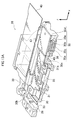
- FIG. 18 is schematic diagram of an image blur correction apparatus of a digital camera of a fourth embodiment of the presently disclosed subject matter
- FIG. 19 is a B-B cross-sectional view of the image blur correction apparatus during imaging
- FIG. 20 is a B-B cross-sectional view of the image blur correction apparatus during exhausting heat
- FIG. 21 is a flow chart illustrating a flow of a process of the digital camera of the fourth embodiment
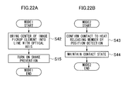
- FIG. 22A is a flow chart illustrating a flow of a process of the mode 1 of the digital camera of the fourth embodiment
- FIG. 22B is a flow chart illustrating a flow of a process of the mode 2 of the digital camera of the fourth embodiment
- FIG. 23 is a schematic diagram of an image blur correction apparatus of a digital camera of a fifth embodiment of the presently disclosed subject matter.
- FIGS. 24A and 24B are diagrams explaining generation of elastic force by a main flexible substrate
- FIG. 25A is a schematic diagram of an image blur correction apparatus of a digital camera of a sixth embodiment of the presently disclosed subject matter, illustrating a state during imaging
- FIG. 25B is a schematic diagram of the image blur correction apparatus of the digital camera of the sixth embodiment of the presently disclosed subject matter, illustrating a state during exhausting heat
- FIG. 26 is a flow chart illustrating a flow of a process of a digital camera of a seventh embodiment of the presently disclosed subject matter
- FIG. 27 is a flow chart illustrating a flow of a process of the mode 1 of the digital camera of the seventh embodiment
- FIG. 28A is a diagram illustrating a position of an image pickup element during normal imaging.
- FIG. 28B is a diagram illustrating a position of the image pickup element during exhausting heat
- FIGS. 1A and 1B are schematic diagrams of a digital camera 1 according to a first embodiment of the digital camera 1 comprising the image blur correction apparatus according to the presently disclosed subject matter.
- FIG. 1A is a front side perspective view
- FIG. 1B is a back side perspective view.
- the digital camera 1 can record and play back not only still images, but also moving images, sounds, etc.
- a camera body 11 of the digital camera 1 is formed in a horizontally long rectangular box shape.
- An optical system 12 , a stroboscope 14 , etc. are arranged on the front side.
- a shutter button 15 , a power button 16 , a mode dial 17 , etc. are arranged on the upper side of the camera body 11 .
- a monitor 18 , a zoom button 19 , arrow buttons 20 , a MENU/OK button 21 , a DISP/BACK button 22 , a playback button 23 , etc. are arranged on the back side of the camera body 11 .
- the lower surface of the camera body 11 includes: tripod screw holes; and a battery insertion section and a memory card slot through a freely opened/closed cover. A battery and a memory card are loaded on the battery insertion section and the memory card slot.
- the optical system 12 is included in a collapsible lens barrel. As the mode of the camera is set to an imaging mode by the power button 16 , the lens cover 13 opens, and the zoom lens is drawn out from the camera body 11 . Though specific configurations of the zoom mechanism and the collapsible mechanisms of the optical system 12 will not be described here, details of the optical system 12 will be described later.
- a light emission unit of the stroboscope 14 is configured to be able to swing in the horizontal direction and the vertical direction to direct stroboscopic light toward a main subject.
- the shutter button 15 is constituted by a two-step stroke switch including so-called “half-press” and “full-press”.
- still image photographing for example, when a still image photographing mode is selected by the mode dial 17 or when the still image photographing mode is selected from the menu
- the digital camera 1 executes imaging preparation processes, or processes of AE (Automatic Exposure), AF (Auto Focus), and AWB (Automatic White Balance), when the shutter button 15 is half-pressed (S 1 ON) and executes a photographing and recording process of an image when the shutter button 15 is full-pressed (S 2 ON).
- AE Automatic Exposure
- AF Automatic Focus
- AWB Automatic White Balance
- the digital camera 1 starts photographing moving images when the shutter button 15 is pressed for a long time and ends photographing the moving images when the shutter button 15 is full-pressed for a predetermined time again.
- the digital camera 1 can be configured to photograph moving images while the shutter button 15 is full-pressed and to end photographing the moving images when the full-press is released.
- the power button 16 is a button for switching on/off of the power of the digital camera 1 .
- the mode dial 17 is used to switch various modes (such as imaging mode, playback mode, deletion mode, and edit mode) and to set imaging modes, such as automatic imaging and manual imaging.
- the monitor 18 has a typical aspect ratio of 4:3 and is constituted by a liquid crystal display capable of color display.
- the monitor 18 is used as an image display panel for displaying photographed images during the playback mode and as a photographer interface display panel for various setting operations.
- a live view image (through image) is displayed as necessary during the imaging mode, and the monitor 18 is also used as an electronic finder for confirming the angle of view.
- the zoom button 19 is used for a zoom operation of the optical system 12 and is constituted by a zoom tele button for instructing zooming to the telephoto side and a zoom wide button for instructing zooming to the wide side.
- the arrow buttons 20 are buttons for selecting various settings of menu or for zooming and is configured to be able to perform pressing operations in vertical and horizontal four directions.
- a function corresponding to the setting state of the camera is allocated to the button in each direction. For example, during imaging, a function for switching on/off of a macro function is allocated to the left button, and a function for switching a stroboscopic mode is allocated to the right button.
- a function for switching the brightness of the monitor 18 is allocated to the up button, and a function for switching on/off of a self-timer is allocated to the down button.
- a function for frame advancing is allocated to the right button, and a function for frame rewinding is allocated to the left button.
- a function for switching the brightness of the monitor 18 is allocated to the up button, and a function for deleting an image being played back is allocated to the down button.
- a function for moving the cursor displayed on the monitor 18 in directions of the buttons is allocated.
- the MENU/OK button 21 is used to call out the menu screen (MENU function), confirm the selected content, instruct the execution of process, etc. (OK function). Functions allocated in accordance with the setting state of the digital camera 1 are switched. On the menu screen, all adjustment items included in the digital camera 1 are set, the items including image quality adjustment, such as exposure value, hue, photographic sensitivity (ISO sensitivity), and the number of recorded pixels, as well as setting of self-timer, switching of light measurement system, whether to use digital zooming, etc. The digital camera 1 operates in accordance with the conditions set on the menu screen.
- the DISP/BACK button 22 is used to input an instruction to switch the display content of the monitor 18 , etc. and to input an instruction to cancel the input operation, etc.
- the playback button 23 is used to instruct switching to the playback mode.
- the optical system 12 mainly includes an aperture, a focus lens, a zoom lens (which are not illustrated), and an image blur correction apparatus 24 .
- the image blur correction apparatus 24 detects shaking of the digital camera 1 by gyro sensors 71 and 74 (see FIG. 5 ) and moves an image pickup element 55 (see FIG. 5 ) in the direction opposite the shaking of the digital camera 1 to correct the image blur of the subject image formed in the image pickup element 55 .
- FIG. 2 is a diagram illustrating an outline of the image blur correction apparatus 24 when the image pickup element 55 is on the optical axis (position substantially corresponding to the optical axis), while the digital camera 1 is held at a regular orientation (orientation of FIG. 1A ).
- the image blur correction apparatus 24 includes a CCD (charge-coupled device) case 30 , a CCD plate 31 , a voice coil motor 32 , a main guide axis 33 , a rotation stopping guide axis 34 , a voice coil motor 35 , a main guide axis 36 , a rotation stopping guide axis 37 , a slider 38 , a frame 39 , a main flexible substrate 40 , and a flexible substrate 41 for voice coil motor.
- CCD charge-coupled device
- the CCD case 30 is a resin member for holding the image pickup element 55 .
- a bearing 30 a is formed near the right side (+x side) upper end (+y side) of the CCD case 30 , and the rotation stopping guide axis 34 is inserted.
- Bearings 30 b are formed at two parts on the left side ( ⁇ x direction) of the CCD case 30 , and the main guide axis 33 is inserted to the bearings 30 b.
- the CCD plate 31 is a metallic plate-like member and is used for tilt adjustment, etc.
- the CCD plate 31 is screwed on the front side (+z side) of the CCD case 30 so as to cover the CCD case 30 .
- a hole is formed at substantially the center of the CCD plate 31 , and the image pickup element 55 is exposed from the hole.
- a rib-like convex portion 31 a is formed along the edge of the right side of FIG. 2 .
- the voice coil motors 32 and 35 are driven according to a signal outputted from a motor driver 77 (see FIG. 5 ).
- the voice coil motor 32 moves the CCD case 30 and the CCD plate 31 in the y direction
- the voice coil motor 35 moves the CCD case 30 , the CCD plate 31 , and the slider 38 in the x direction.
- the structures of the voice coil motors 32 and 35 are the same except that a heat exhausting (dissipating or releasing) member 35 d (described in detail later) is not arranged on the voice coil motor 32 . Therefore, the voice coil motor 35 will be described.
- FIG. 3 is an A-A cross section of FIG. 2 .
- the voice coil motor 35 includes yokes 35 a , a coil 35 b , a magnet 35 c , and a heat exhausting member 35 d.
- the yokes 35 a are metallic plates fixed to the frame 39 .
- the yokes 35 a are designed to reduce the flux leakage by the magnet 35 c and strengthen the magnetic field between the yokes 35 a .
- One of the yokes 35 a is arranged adjacent to the magnet 35 c , and the other yoke 35 a is arranged at a position sandwiching the coil 35 b and the magnet 35 c by the yokes 35 a .
- the metallic heat exhausting member 35 d is integrally formed on the front side of the other yoke 35 a.
- the magnet 35 c is a magnet, both sides of which are multipolar, and is arranged adjacent to the front side of the yokes 35 a .
- an upward (+z direction) magnetic field is generated on the left side ( ⁇ x side) of FIG. 3 and a downward ( ⁇ z direction) magnetic field is generated on the right side (+x side) (see arrows in FIG. 3 ).
- the directions of the magnetic fields illustrated in FIG. 3 are examples and are not limited to these.
- the coil 35 b is a cylindrical air core coil that is fixed at the edge of the CCD plate 31 and that has a substantially rectangular cross section.
- the helix direction of the coil 35 b is counterclockwise as seen from the +z direction, and the coil 35 b is formed to overlap in the optical axis direction (z direction).
- the helix direction of the coil 35 b is an example and is not limited to this.
- the coil 35 b is fixed to a convex portion 30 c formed on the right side of the CCD case 30 and is arranged in the magnetic field by the magnet 35 c . Therefore, when an electric current is applied to the coil 35 b , force in the vertical direction of both the magnetic field and the electric current is generated due to the Fleming's left-hand rule.
- the magnet 35 c Since the magnet 35 c is fixed to the frame 39 , the magnet 35 c moves in the vertical direction of both the magnetic field and the electric current, i.e. in the x direction, by the force. Accordingly, the CCD case 30 and the CCD plate 31 , i.e. the image pickup element 55 , also move in the x direction.
- FIG. 4 illustrates a state after the CCD case 30 and the CCD plate 31 have moved in the +x direction to the maximum from the state in which the image pickup element 55 illustrated in FIG. 3 is on the optical axis.
- the CCD case 30 and the CCD plate 31 can move to the position where the convex portion 31 a and the heat exhausting member 35 d are in contact.
- the heat generated by the image pickup element 55 is transferred to the CCD plate 31 through the CCD case 30 .
- the heat transferred to the CCD plate 31 is transferred to the heat exhausting member 35 d (see an arrow in FIG. 4 ) and exhausted into the air from the heat exhausting member 35 d.
- the main guide axis 33 is an axis for moving the CCD case 30 and the CCD plate 31 in the y direction.
- the main guide axis 33 is inserted to the bearings 30 b and fixed to the slider 38 .
- the rotation stopping guide axis 34 is designed to stop the CCD case 30 and the CCD plate 31 from rotating around the main guide axis 33 .
- the rotation stopping guide axis 34 is inserted to a through hole 30 b and fixed to the slider 38 .
- the main guide axis 33 and the rotation stopping guide axis 34 are arranged at both sides of the image pickup element 55 in parallel.
- the slider 38 is a substantially square-shaped member that moves the CCD case 30 and the CCD plate 31 in the x direction. As the slider 38 is substantially square-shaped, the strength of the slider 38 is maintained. Bearings 38 a are formed at two parts near both ends on the upper side (+y direction) of the slider 38 , and the main guide axis 36 is inserted. A bearing 38 b is formed near the lower side ( ⁇ y direction) left end ( ⁇ x direction) of the slider 38 , and the rotation stopping guide axis 37 is inserted.
- the main guide axis 36 is an axis for moving the slider 38 in the x direction.
- the main guide axis 36 is inserted to the bearings 38 a and is fixed to the frame 39 .
- the rotation stopping guide axis 37 is designed to stop the slider 38 from rotating around the main guide axis 36 .
- the rotation stopping guide axis 37 is inserted to the bearing 38 b and fixed to the frame 39 .
- the main guide axis 36 and the rotation stopping guide axis 37 are arranged at both sides of the image pickup element 55 in parallel.
- the frame 39 is a member for fixing the main guide axis 36 and the rotation stopping guide axis 37 inside the camera body 11 .
- the main flexible substrate 40 and the flexible substrate 41 for voice coil motor are bendable thin substrates.
- the main flexible substrate 40 supplies power to the image pickup element 55 and electrically connects a main substrate not illustrated and the image pickup element 55 .
- the flexible substrate 41 for voice coil motor supplies power to the voice coil motors 32 and 35 and electrically connects the main substrate not illustrated and the voice coil motors 32 and 35 .
- the digital camera 1 includes a CPU (central processing unit) 50 , an operation device (the shutter button 15 , the power button 16 , the mode dial 17 , the zoom button 19 , the arrow button 20 , the MENU/OK button 21 , the DISP/BACK button 22 , the playback button 23 , etc.) 51 , an SDRAM (synchronous dynamic random access memory) 52 , an EEPROM (electrically erasable programmable read-only memory) 53 , a timing generator (TG) 54 , the image pickup element 55 , an analog signal processing device (CDS/AMP) 56 , an A/D (analog-to-digital) converter 57 , an image input controller 58 , an image signal processing device 59 , a compression/decompression processing device 60 , an AE/AWB detection device 61 , an AF detection device 62 , a video encoder 63 , a media controller 64 ,
- a CPU central processing unit
- an operation device the shutter button 15 ,
- the CPU 50 functions as a control device that comprehensively controls the entire operation of the digital camera 1 , functions as a computation device that executes various computation processes, and controls the components of the digital camera 1 according to predetermined control programs based on input from an operation device 121 , etc.
- the SDRAM 52 is used as a working area of the CPU 50 and as a temporary storage area of image data, etc.
- the EEPROM 53 is a non-volatile memory and stores programs for various controls, setting information, etc.
- the main CPU 50 executes various processes based on the programs and the setting information.
- the TG 54 controls an optical charge storage/transfer operation of the image pickup element 55 .
- a timing signal (clock pulse) inputted from the TG 54 determines the electronic shutter speed (optical charge storage time).
- the image pickup element 55 is a CCD image sensor arranged on the lens optical axis and electronically picks up an image of a subject formed by a zoom lens, a focus lens, etc. As illustrated in FIG. 6 , a multiplicity of photodiodes 55 a are two-dimensionally aligned on the light receiving surface of the image pickup element 55 , and each photodiode 55 a converts the subject light directed to the light receiving surface into a signal charge in an amount corresponding to the incident light amount. The signal charge accumulated on the photodiodes 55 a is read out according to a timing pulse provided from the TG 54 , shifted upward of FIG.
- the imaging signals outputted from the image pickup element 55 are inputted to the analog signal processing device 56 .
- the frequency of the voltage signals applied to H 1 and H 2 that drive the horizontal transfer path 55 c is higher and the power consumption is higher than those of the voltage signals applied to V 1 to V 4 that drive the vertical transfer path 55 b . Therefore, the horizontal transfer path 55 c generates the greatest heat in the image pickup element 55 .
- the CCD case 30 , the CCD plate 31 , and the slider 38 are moved in the x direction, and the heat is exhausted from the voice coil motor 35 . Therefore, the image pickup element 55 is arranged in the CCD case so that the horizontal transfer path 55 c that generates the most heat and the heat exhausting member are brought into contact in a shortest distance and that the horizontal transfer path 55 c is located in the +x direction.
- the analog signal processing device 56 applies a correlated dual sampling process (a process of calculating a difference between a feedthrough component level and a pixel signal component level included in an output signal of each pixel of the image pickup element to obtain accurate pixel data in order to reduce noise (especially thermal noise), etc. included in the output signal of the image pickup element) to each image signal outputted from the image pickup element 55 to amplify and output the image signal.
- a correlated dual sampling process a process of calculating a difference between a feedthrough component level and a pixel signal component level included in an output signal of each pixel of the image pickup element to obtain accurate pixel data in order to reduce noise (especially thermal noise), etc. included in the output signal of the image pickup element
- the A/D converter 57 converts the inputted image data from analog to digital.
- the image pickup element 55 of the optical system 12 is outputted as image data through the A/D converter 57 .
- the image input controller 58 includes a buffer memory (line buffer) with predetermined capacity. In accordance with a command from the CPU 50 , the image input controller 58 accumulates image signals of one image outputted from the A/D converter 57 and records the image signals in the SDRAM 52 .
- the image signal processing device 59 includes a synchronization (signal interpolating) circuit (a processing circuit that interpolates spatial deviation of color signals associated with single-plate CCD color filter alignment to synchronously convert the color signals), a white balance correction circuit, a gamma correction circuit, a contour correction circuit, a luminance/color difference signal generation circuit, etc.
- the image signal processing device 59 applies required signal processing to the image data inputted from the A/D converter 57 to generate image data (YUV data) including luminance data (Y data) and color difference data (Cr, Cb data) and outputs the image data to the video encoder 63 for display.
- the generated image data is displayed as a live view image (through image) on the monitor 18 through the video encoder 63 .
- the image signal processing device 59 further converts the image data taken by the image pickup element 55 and the YC signal of the image data taken by the image pickup element 55 into a video signal of a predetermined system (for example, color complex video signal of an NTSC (National Television System Committee) system) and then composes stereoscopic image data to be stereoscopically displayed by an external stereoscopic image display device, etc.
- a predetermined system for example, color complex video signal of an NTSC (National Television System Committee) system
- the compression/decompression processing device 60 applies a compression process in a predetermined format to the inputted image data to generate compressed image data.
- the compression/decompression processing device 60 further applies a compression process to the image data stored in the SDRAM 52 in accordance with a predetermined compression format, such as JPEG (Joint Photographic Experts Group) for still images, MPEG2 (Moving Picture Experts Group 2), MPEG4, or H.264 system for moving images.
- the compression/decompression processing device 60 stores data of two-dimensional still images in recording media 65 as an image file (the image file will be described in detail later) in a predetermined format such as an Exif (Exchangeable image file format) file.
- the Exif file includes an area for storing data of main images and an area for storing data of reduced images (thumbnail images). Thumbnail images in a prescribed size (for example, 160 ⁇ 120 or 80 ⁇ 60 pixels) are generated from the data of the main images acquired by imaging, through a thinning-out process of pixels and other necessary data processing. The generated thumbnail images are written in the Exif file along with the main images. Tag information, such as photographed date/time, photographed conditions, and face detection information, is attached to the Exif file.
- the AE/AWB detection device 61 calculates physical quantity necessary for AE control and AWB control from the inputted image signals in accordance with a command from the CPU 50 .
- the physical quantity necessary for AE control one screen is divided into a plurality of areas (for example, 16 ⁇ 16), and an integrated value of R (red), G (green), and B (blue) image signals is calculated in each divided area.
- the CPU 50 detects brightness of the subject (subject luminance) based on the integrated value obtained from the AE/AWB detection device 61 to calculate an exposure value (imaging EV value) suitable for imaging.
- the aperture value and the shutter speed are determined from the calculated imaging EV value and a predetermined program diagram.
- the AE/AWB detection device 61 divides one screen into a plurality of areas (for example, 16 ⁇ 16) and calculates an average integrated value of each color of R, G, and B image signals in each divided area which is one of the physical quantity necessary for AWB control.
- the CPU 50 calculates ratios of R/G and B/G in each divided area from the obtained integrated value of R, integrated value of B, and integrated value of G and determines the light source type based on the distribution of the obtained values of R/G and B/G in the color spaces of R/G and B/G.
- a gain value (white balance adjustment value) for the R, G, and B signals of the white balance adjustment circuit is determined so that, for example, the values of the ratios are about 1 (in other words, the integration ratio of RGB is R:G:B ⁇ 1:1:1 in one screen).
- the AF detection device 62 calculates physical quantity necessary for AF control from the inputted image signals in accordance with a command from the CPU 50 .
- AF control is performed based on the contrast of the image obtained from the image pickup element 55 (so-called contrast AF), and the AF detection device 62 calculates a focus evaluation value indicating the sharpness of the image from the inputted image signals.
- the CPU 50 detects a position where the focus evaluation value calculated by the AF detection device 62 is local maximum and moves the focus lens group to the position. More specifically, the CPU 50 moves the focus lens group from the closest range to the infinity by predetermined steps, acquires a focus evaluation value at each position, sets the position in which the obtained focus evaluation value is maximum as a focused position, and moves the focus lens group to the position.
- the video encoder 63 outputs the RGB signals outputted from the image signal processing device 59 to the monitor 18 .
- the media controller 64 records the image data compressed by the compression/decompression processing device 60 in the recording media 65 or other recording media connected through the media controller 64 .
- the recording media 65 are various recording media, such as a semiconductor memory card, a portable compact hard disk, a magnetic disk, an optical disk, and a magneto-optical disk, represented by xD Picture Card (registered trademark) and Smart Media (registered trademark) removable from the digital camera 1 .
- a power battery is removably arranged on the digital camera 1 .
- the power battery is constituted by a chargeable second battery, such as a NiCad battery, a nickel hydrogen battery, and a lithium ion battery.
- the power battery may be constituted by a non-chargeable primary battery, such as a lithium battery and an alkaline battery.
- the power battery is loaded on a battery storage chamber not illustrated and electrically connected to the devices of the digital camera 1 .
- the gyro sensors 71 and 74 are sensors that detect the angular velocity of the digital camera 1 and that detect a vibration of the digital camera 1 due to camera shake.
- the gyro sensor 71 detects the acceleration in the x direction (see FIG. 2 )
- the gyro sensor 74 detects the acceleration in the y direction (see FIG. 2 ).
- the amplifiers 72 and 75 amplify the signals detected by the gyro sensors 71 and 74 and output the signals to the A/D converters 73 and 76 .
- the A/D converters 73 and 76 respectively convert the signals amplified by the amplifiers 72 and 75 to digital signals and input the converted signals to the CPU 50 .
- the CPU 50 amplifies the signals inputted from the gyro sensors 71 and 74 and outputs the signals to the motor driver 77 .
- the motor driver 77 drives the voice coil motors 32 and 35 based on the signals inputted from the CPU 50 .
- the position detection elements 78 and 79 are, for example, hall elements and detect the position of the CCD plate 31 .
- the position detection element 78 detects the position in the y direction, and the position detection element 79 detects the position in the x direction.
- the position detection element 78 detects the position every time the slider 38 moves in the y direction, and the position detection element 79 detects the position every time the CCD plate 31 moves in the x direction.
- FIG. 7 is a flow chart illustrating a flow of a process of the digital camera 1 .
- the CPU 50 mainly executes the following process.
- step S 2 the CPU 50 drives the image blur correction apparatus 24 in a mode 2 (step S 2 ).
- step S 2 the CPU 50 applies an electric current to the coil 35 b to drive the voice coil motor 35 to thereby move the CCD case 30 and the CCD plate 31 in the +x direction and brings the convex portion 31 a into contact with the heat exhausting member (step S 11 ).
- the position detection element 79 detects the position of the CCD plate 31 (step S 12 ).
- the CPU 50 applies an electric current to the coil 35 b and drives the voice coil motor 35 to terminate the CCD case 30 and the CCD plate 31 while the convex portion 31 a and the heat exhausting member 35 d are in contact (step S 13 ).
- the CPU 50 detects whether the operation mode of the digital camera 1 is the imaging mode (step S 3 ). If the digital camera 1 is not in the imaging mode (NO in step S 3 ), step S 3 is executed again.
- the image blur correction apparatus 24 is driven in the mode 1 to perform image blur correction concurrently with photographing of the live view image (step S 4 ).
- step S 4 The process of step S 4 will be described.
- the CPU 50 first uses the position detection element 79 to detect the position in the x direction and applies an electric current to the coil 35 b if the center of the image pickup element 55 and the optical axis do not correspond to bring the center of the image pickup element 55 into line with the optical axis (step S 14 ).
- the image pickup element 55 consecutively picks up images and consecutively processes the image signals to generate image data for live view image.
- the generated image data is sequentially inputted to the video encoder 63 , converted into a signal format for display, and outputted to the monitor 18 . This starts photographing for through image by the image pickup element 55 .
- the CPU 50 executes a shake prevention process of correcting an image blur of a subject image picked up by the image pickup element 55 caused by vibration (such as camera shake) applied to the digital camera 1 (step S 15 ), as described below.
- the detection signal is inputted to the CPU 50 through the amplifiers 72 and 75 and the A/D converters 73 and 76 .
- the CPU 50 drives the voice coil motor 35 through the motor driver 77 based on the signal inputted from the gyro sensor 71 .
- the CPU 50 also drives the voice coil motor 32 through the motor driver 77 based on the signal inputted from the gyro sensor 74 .
- the voice coil motors 32 and 35 are driven, the position detection elements 78 and 79 detect the positions in the y direction and the x direction and output the result to the CPU 50 .
- the CPU 50 controls the voice coil motors 32 and 35 so that the position inputted from the position detection elements 78 and 79 becomes the target position. This allows an appropriate shake prevention operation.
- the CPU 50 determines whether the shutter button 15 is half-pressed, in other words, whether an S 1 ON signal is inputted to the CPU 50 (step S 5 ). If the S 1 ON signal is not inputted (NO in step S 5 ), step S 5 is executed again. If the S 1 ON signal is inputted (YES in step S 5 ), the following imaging preparation processes, in other words, AE, AF, and AWB processes, are executed in response to the S 1 ON signal (step S 6 ).
- the image signal imported from the image pickup element 55 is inputted to an AF detection device 138 and an AE/AWB detection device 139 .
- the data of an integrated value calculated by the AF detection device 138 is reported to the CPU 50 .
- the CPU 50 computes focus evaluation values (AF evaluation values) at a plurality of AF detection points while moving the focus lens group of the optical system 12 and determines the lens position where the evaluation value is local maximum as the focused position.
- the CPU 50 moves the focus lens group to the calculated focused position.
- the CPU 50 detects the brightness of the subject (subject luminance) based on the integrated value obtained from the AE/AWB detection device 139 and calculates an exposure value (imaging EV value) suitable for imaging.
- the CPU 50 determines the aperture value and the shutter speed from the calculated EV imaging value and a predetermined program diagram and controls the electronic shutter and the aperture of the image pickup element 55 according to the aperture value and the shutter speed to obtain an appropriate amount of exposure.
- whether light emission of stroboscope 14 is necessary is determined from the detected subject luminance.
- the AE/AWB detection device 139 calculates an average integrated value of each color of R, G, and B signals in each divided area and provides the calculation result to the CPU 50 .
- the CPU 50 calculates ratios of R/G and B/G in each divided area from the obtained integrated value of R, integrated value of B, and integrated value of G and determines the light source type based on the distribution of the calculated values of R/G and B/G in the color spaces of R/G and B/G.
- a gain value (white balance correction value) for the R, G, and B signals of the white balance adjustment circuit is controlled so that, for example, the values of the ratios are about 1 (in other words, the integration ratio of RGB is R:G:B ⁇ 1:1:1 in one screen), and the signal of each channel is corrected.
- the AE/AF process is executed by the half-press of the shutter button 15 .
- the photographer operates the zoom button 19 as necessary to zoom the lens 14 to adjust the angle of field.
- the CPU 50 determines whether the shutter button 15 is full-pressed, in other words, whether an S 2 ON signal is inputted to the CPU 50 (step S 7 ). If the S 2 ON signal is not inputted (NO in step S 7 ), step S 5 is executed again. If the S 2 ON signal is inputted (YES in step S 7 ), the following imaging process and recording process (step S 8 ) are executed in response to the S 2 ON signal.
- the image pickup element 55 is first exposed by the aperture value and the shutter speed obtained in the AE process to pick up an image for recording.
- the image signals outputted from the image pickup element 55 are imported through the analog signal processing device 56 , the A/D converter 57 , and the image input controller 58 and stored in the SDRAM 52 .
- the image signals stored in the SDRAM 52 are inputted to the image signal processing device 59 .
- the image signal processing device 59 applies predetermined signal processing to the inputted image signals to generate image data (YUV data) including luminance data and color difference data.
- the image data generated by the image signal processing device 59 is temporarily stored in the SDRAM 52 and then inputted to the media controller 64 .
- the media controller 64 applies predetermined compression processing to the inputted image data to generate compressed image data.
- the compressed image data is stored in the SDRAM 52 and recorded in the recording media 65 through the media controller 64 as a still image file (for example, Exif) in a predetermined format.
- the CPU 50 drives the image blur correction apparatus 24 in the mode 2 (step S 2 ).
- the convex portion 31 a of the CCD plate 31 touches the heat exhausting member 35 d , and the heat generated by the image pickup element 55 in the imaging preparation process (step S 7 ) and the imaging process (step S 8 ) is exhausted from the heat exhausting member 35 d.
- the CPU 50 inputs the compressed image data generated in step S 8 to the compression/decompression processing device 60 , converts the compressed image data to uncompressed image data, inputs the image data to the SDRAM 52 , and performs preview display by outputting the image data from the SDRAM 52 to the monitor 18 through the video encoder 63 (step S 9 ).
- the image blur correction apparatus 24 is driven in the mode 2 during the preview display (step S 9 ), and the heat is continuously exhausted.
- the CPU 50 detects whether the operation mode of the digital camera 1 is the imaging mode (step S 3 ). If the digital camera 1 is in the imaging mode (YES in S 3 ), the image blur correction apparatus 24 is driven in the mode 1 to perform image blur correction concurrently with photographing of the through image (step S 4 ). In this way, even in the continuous imaging, the image blur correction apparatus 24 is driven in the mode 2 until just before (step S 2 ). Therefore, an increase in the temperature of the image pickup element 55 can be prevented, and the noise of image caused by heat can be reduced.
- step S 10 determines whether the power is off is determined. If the power is not off (NO in step S 10 ), step S 3 is executed again. If the power is off (YES in step S 3 ), the process ends.
- step S 9 the image taken in step S 8 can be confirmed.
- the CPU 50 switches the digital camera 1 to the playback mode.
- the CPU 50 reads out the compressed image data of the image file recorded lastly. If the lastly recorded image file is recorded in the recording media 65 , the CPU 50 reads out the compressed image data of the image file lastly recorded in the recording media 65 through the media controller 64 .
- the compressed image data read out from the recording media 65 is inputted to the compression/decompression processing device 60 , converted to uncompressed image data, and then inputted to the SDRAM 52 .
- the data is outputted from the SDRAM 52 to the monitor 18 through the video encoder 63 .
- images recorded in the recording media 65 or a flash ROM 114 are played back and displayed on the monitor 18 .
- the image blur correction apparatus 24 is driven in the mode 2 during the process (step S 2 ). Therefore, an increase in the temperature of the image pickup element 55 can be prevented.
- the load is not imposed on the driven objects. Therefore, the mass of the driven objects does not increase in the image blur correction. As a result, the shake prevention performance is not degraded, and the heat generated in the image pickup element can be efficiently exhausted.
- the shake prevention process is turned off when the preview display is performed after imaging, and the CCD plate and the heat exhausting member are brought into contact. Therefore, the heat can be efficiently exhausted. As a result, an increase in the temperature of the image pickup element can be prevented during continuous imaging, etc., and the noise can be reduced.
- the heat exhausting member 35 d and the camera body 11 may be brought into contact directly or through a heat-transfer member to exhaust the heat to the outside from the camera body 11 .
- the position detection element 79 detects the position of the CCD plate 31 (step S 12 ) in the mode 2 (step S 2 ).
- the position detection element 79 detects that the convex portion 31 a and the heat exhausting member 35 d are in contact, and the CCD case 30 and the CCD plate 31 are terminated while the convex portion 31 a and the heat exhausting member 35 d are in contact (step S 13 ).
- the convex portion 31 a and the heat exhausting member 35 d may be separated as an impact, etc. is applied to the digital camera 1 . Therefore, as illustrated in FIG.
- step S 9 the CCD case 30 and the CCD plate 31 are terminated while the convex portion 31 a and the heat exhausting member 35 d are in contact (step S 13 ), and then the position detection element 79 detects whether the convex portion 31 a and the heat exhausting member 35 d are not in contact any more (step S 15 ). If the position detection element 79 detects that the convex portion 31 a and the heat exhausting member 35 d are not in contact any more (YES in step S 15 ), the CCD case 30 and the CCD plate 31 may be moved in the +x direction to bring the convex portion 31 a and the heat exhausting member 35 d into contact (step S 11 ).
- CMOS complementary metal-oxide semiconductor
- the voice coil motor is used as the actuator of the image blur correction apparatus
- the actuator is not limited to the voice coil motor.
- an expandable actuator, etc. using a stepping motor, a piezoelectric element, etc. may be used.
- the image blur correction apparatus 24 is driven in the mode 2 to bring the convex portion 31 a of the CCD plate 31 and the heat exhausting member 35 d into contact to exhaust the heat.
- an electric current needs to be continuously applied to the coil 35 b of the voice coil motor 35 to maintain the convex portion 31 a and the heat exhausting member 35 d that are in contact.
- the coil 35 b consumes power, and the coil 35 b generates heat. This results in the generation of heat to exhaust heat.
- a second embodiment is an embodiment in which an elastic member is used to bring the convex portion 31 a of the CCD plate 31 and the heat exhausting member 35 d into contact.
- a digital camera 2 according to the second embodiment will be described.
- the same parts as in the first embodiment are designated with the same reference numerals, and the description will not be repeated.
- the camera body 11 of the digital camera 2 is formed in a horizontally long rectangular box shape.
- An optical system 12 A, the stroboscope 14 , etc. are arranged on the front side.
- the shutter button 15 , the power button 16 , the mode dial 17 , etc. are arranged on the upper side of the camera body 11 .
- the monitor 18 , the zoom button 19 , the arrow buttons 20 , the MENU/OK button 21 , the DISP/BACK button 22 , the playback button 23 , etc. are arranged on the back side of the camera body 11 .
- the optical system 12 A includes an aperture, a focus lens, a zoom lens (which are not illustrated), and an image blur correction apparatus 25 .
- the image blur correction apparatus 25 detects shaking of the digital camera 1 by the gyro sensors 71 and 74 (see FIG. 5 ) and moves the image pickup element 55 (see FIG. 5 ) in the direction opposite the shaking of the digital camera 1 to correct the image blur of the subject image formed in the image pickup element 55 .
- FIGS. 10A and 10B are transverse sectional views of the image blur correction apparatus 25 .
- the image blur correction apparatus 25 includes the CCD case 30 , the CCD plate 31 , the voice coil motor 32 , the main guide axis 33 , the rotation stopping guide axis 34 , the voice coil motor 35 , the main guide axis 36 , the rotation stopping guide axis 37 , the slider 38 , the frame 39 , the main flexible substrate 40 , the flexible substrate 41 for voice coil motor, and a spring 42 .
- the spring 42 is arranged between the CCD plate 31 and the frame 39 .
- the spring 42 applies energization force to the CCD plate 31 in the +x direction. Therefore, if the electric current is not applied to the coil 35 b of the voice coil motor 35 , the convex portion 31 a and the heat exhausting member 35 d are in contact as illustrated in FIG. 9B .
- an electric current is applied to the coil 35 b of the voice coil motor 35 , and the convex portion 31 a and the heat exhausting member 35 d are separated as illustrated in FIG. 9A .
- the spring 42 is used to prevent the backlash of mechanics between the main guide axis 33 and the bearing 30 b.
- FIG. 11 is a flow chart illustrating a flow of a process of the digital camera 2 .
- the CPU 50 mainly executes the following process.
- step S 1 When the power button is pressed to turn on the power of the digital camera 2 (step S 1 ), the CPU 50 drives the image blur correction apparatus 25 in the mode 2 (step S 20 ). As illustrated in FIG. 12B , in step S 20 , when the CPU 50 stops applying the electric current to the coil 35 b , the energization force of the spring 42 moves the CCD case 30 and the CCD plate 31 in the +x direction, and the convex portion 31 a and the heat exhausting member 35 d are brought into contact (step S 22 ).
- the CPU 50 detects whether the operation mode of the digital camera 2 is the imaging mode (step S 3 ). If the digital camera 2 is not in the imaging mode (NO in step S 3 ), step S 3 is executed again.
- step S 3 If the digital camera 2 is in the imaging mode (YES in step S 3 ), the image blur correction apparatus 25 is driven in the mode 1 to perform image blur correction concurrently with photographing of the through image (step S 21 ).
- step S 21 The process of step S 21 will be described.
- the CPU 50 first applies an electric current to the coil 35 b to move the CCD case 30 and the CCD plate 31 in the ⁇ x direction against the energization force of the spring 42 and brings the center of the image pickup element 55 into line with the optical axis (step S 23 ).
- the image pickup element 55 consecutively picks up images and consecutively processes the image signals to generate image data for through image.
- the generated image data is sequentially inputted to the video encoder 63 , converted to a signal format for display, and outputted to the monitor 18 . This starts photographing for through image by the image pickup element 55 .
- the CPU 50 executes a shake prevention process of correcting an image blur of a subject image picked up by the image pickup element 55 caused by vibration (such as camera shake) applied to the digital camera 2 (step S 15 ).
- the CPU 50 determines whether the shutter button 15 is half-pressed, in other words, whether an S 1 ON signal is inputted to the CPU 50 (step S 5 ). If the S 1 ON signal is not inputted (NO in step S 5 ), step S 5 is executed again. If the S 1 ON signal is inputted (YES in step S 5 ), imaging preparation processes, in other words, AE, AF, and AWB processes, are executed in response to the S 1 ON signal (step S 6 ).
- the CPU 50 determines whether the shutter button 15 is full-pressed, in other words, whether an S 2 ON signal is inputted to the CPU 50 (step S 7 ). If the S 2 ON signal is not inputted (NO in step S 7 ), step S 5 is executed again. If the S 2 ON signal is inputted (YES in step S 7 ), the imaging process and recording process (step S 8 ) are executed in response to the S 2 ON signal.
- the CPU 50 drives the image blur correction apparatus 25 in the mode 2 (step S 20 ).
- the convex portion 31 a of the CCD plate 31 touches the heat exhausting member 35 d , and the heat generated by the image pickup element 55 in the imaging preparation process (step S 7 ) and the imaging process (step S 8 ) is exhausted from the heat exhausting member 35 d.
- the CPU 50 inputs the compressed image data generated in step S 8 to the compression/decompression processing device 60 , converts the compressed image data to uncompressed image data, inputs the image data to the SDRAM 52 , and performs preview display by outputting the image data from the SDRAM 52 to the monitor 18 through the video encoder 63 (step S 9 ).
- the image blur correction apparatus 25 is driven in the mode 2 during the preview display (step S 9 ), and the heat generated by the image pickup element 55 is continuously exhausted.
- the CPU 50 detects whether the operation mode of the digital camera 2 is the imaging mode (step S 3 ). If the digital camera 2 is in the imaging mode (YES in S 3 ), the image blur correction apparatus 25 is driven in the mode 1 to perform image blur correction concurrently with photographing of the through image (step S 21 ).
- step S 10 determines whether the power is off is determined. If the power is not off (NO in step S 10 ), step S 3 is executed again. If the power is off (YES in step S 3 ), the process ends.
- the convex portion 31 a and the heat exhausting member 35 d are always in contact, including when the power is off. Therefore, the power is not consumed to maintain the convex portion 31 a and the heat exhausting member 35 d that are in contact. Therefore, the heat generated by the image pickup element can be more efficiently exhausted. Furthermore, since the voice coil motor does not have to be driven to exhaust the heat, excessive heat is not generated.
- the CCD plate 31 does not vibrate when the power is off because the energization force works on the CCD plate 31 . Therefore, a problem, such as the breakage of the CCD plate 31 or the heat exhausting member 35 d due to carrying or vibration of the digital camera and the generation of garbage, can be prevented.
- the convex portion 31 a and the heat exhausting member 35 d are brought into contact by the energization force of the spring 42 without applying an electric current to the coil 35 b in the mode 2 .
- the contact may not be surely made due to, for example, dispersion in the energization force of the spring. Therefore, the position detection element 79 may be used to detect the positions of the CCD case 30 and the CCD plate 31 , an electric current may be applied to the coil 35 b if the convex portion 31 a and the heat exhausting member 35 d are not in contact to thereby bring the convex portion 31 a and the heat exhausting member 35 d into contact.
- the image blur correction apparatus 24 is driven in the mode 2 to bring the convex portion 31 a of the CCD plate 31 and the heat exhausting member 35 d into contact to exhaust the heat.
- the convex portion 31 a and the heat exhausting member 35 d are both metallic members, the contact may be made in just a tiny area due to the unevenness of surface, the tilt of members, etc.
- a third embodiment is an embodiment in which the convex portion 31 a and the heat exhausting member 35 d are brought into contact through a heat-transfer elastic member.
- a digital camera 3 according to the third embodiment will be described.
- the same parts as in the first embodiment are designated with the same reference numerals, and the description will not be repeated.
- the camera body 11 of the digital camera 3 is formed in a horizontally long rectangular box shape.
- An optical system 12 B, the stroboscope 14 , etc. are arranged on the front side.
- the shutter button 15 , the power button 16 , the mode dial 17 , etc. are arranged on the upper side of the camera body 11 .
- the monitor 18 , the zoom button 19 , the arrow buttons 20 , the MENU/OK button 21 , the DISP/BACK button 22 , the playback button 23 , etc. are arranged on the back side of the camera body 11 .
- the optical system 12 B mainly includes an aperture, a focus lens, a zoom lens (which are not illustrated), and an image blur correction apparatus 26 .
- An image blur correction apparatus 26 detects shaking of the digital camera 3 by the gyro sensors 71 and 74 (see FIG. 5 ) and moves the image pickup element 55 (see FIG. 5 ) in the direction opposite the shaking of the digital camera 3 to correct the image blur of the subject image formed in the image pickup element 55 .
- FIGS. 13A and 13B are transverse sectional views of the image blur correction apparatus 26 .
- the image blur correction apparatus 26 includes the CCD case 30 , the CCD plate 31 , the voice coil motor 32 , the main guide axis 33 , the rotation stopping guide axis 34 , the voice coil motor 35 , the main guide axis 36 , the rotation stopping guide axis 37 , the slider 38 , the frame 39 , the main flexible substrate 40 , the flexible substrate 41 for voice coil motor, and a gel member 43 for exhausting heat.
- the gel member 43 for exhausting heat is an elastic heat-transfer gel (jellied) member, such as silicon, and as illustrated in FIGS. 13A and 13B , is arranged at the edge near the CCD plate 31 of the heat exhausting member 35 d . It is desirable to use a material with more than 1 W/m ⁇ k heat conductivity for the gel member 43 for exhausting heat.
- FIG. 14 is a flow chart illustrating a flow of a process of the digital camera 3 .
- the CPU 50 mainly executes the following process.
- step S 1 When the power button is pressed to turn on the power of the digital camera 3 (step S 1 ), the CPU 50 drives the image blur correction apparatus 26 in the mode 2 (step S 2 ). As a result, as illustrated in FIG. 13B , the convex portion 31 a and the heat exhausting member 35 d are brought into contact through the gel member 43 for exhausting heat, and the contract area increases. Therefore, the heat can be more efficiently exhausted.
- the CPU 50 detects whether the operation mode of the digital camera 3 is the imaging mode (step S 3 ). If the digital camera 3 is not in the imaging mode (NO in step S 3 ), step S 3 is executed again.
- step S 3 If the digital camera 3 is in the imaging mode (YES in step S 3 ), the image blur correction apparatus 26 is driven in the mode 1 to perform image blur correction concurrently with photographing of the through image (step S 30 ).
- step S 30 will be described with reference to FIG. 15 .
- the convex portion 31 a and the heat exhausting member 35 d are in contact through the gel member 43 for exhausting heat. Therefore, the convex portion 31 a and the gel member 43 for exhausting heat may be adhered due to the adhesion of the gel member 43 for exhausting heat. As a result, the convex portion 31 a and the gel member 43 for exhausting heat may not be detached during the shake prevention drive of the image blur correction apparatus 26 , and the shake prevention drive may be impossible. A drop in surrounding light amount, shading, etc. may occur because images are taken at the edge of the image pickup element 55 .
- step S 31 driving force that is greater than normal driving force needs to be provided to the voice coil motor 35 for releasing the contact in order to surely separate the convex portion 31 a and the gel member 43 for exhausting heat even if the convex portion 31 a and the gel member 43 for exhausting heat are adhered. Consequently, the CPU 50 applies, to the coil 35 b , the maximum electric current that can be applied to the coil 35 b and moves the CCD case 30 and the CCD plate 31 in the ⁇ x direction (step S 31 ).
- step S 32 The CPU 50 then uses the position detection element 79 to detect the position in the x direction and confirms that the convex portion 31 a and the gel member 43 for exhausting heat are separated (step S 32 ). If the separation of the convex portion 31 a and the gel member 43 for exhausting heat cannot be confirmed (NO in step S 32 ), step S 31 is executed again.
- step S 33 the image pickup element 55 consecutively picks up images and consecutively processes the image signals to generate image data for a live view image (through image).
- the generated image data is sequentially inputted to the video encoder 63 , converted to a signal format for display, and outputted to the monitor 18 . This starts photographing for through image by the image pickup element 55 .
- the CPU 50 executes a shake prevention process of correcting an image blur of a subject image picked up by the image pickup element 55 caused by vibration (such as camera shake) applied to the digital camera 3 (step S 15 ).
- the CPU 50 determines whether the shutter button 15 is half-pressed, in other words, whether an S 1 ON signal is inputted to the CPU 50 (step S 5 ). If the S 1 ON signal is not inputted (NO in step S 5 ), step S 5 is executed again. If the S 1 ON signal is inputted (YES in step S 5 ), imaging preparation processes, in other words, AE, AF, and AWB processes, are executed in response to the S 1 ON signal (step S 6 ).
- the CPU 50 determines whether the shutter button 15 is full-pressed, in other words, whether an S 2 ON signal is inputted to the CPU 50 (step S 7 ). If the S 2 ON signal is not inputted (NO in step S 7 ), step S 5 is executed again. If the S 2 ON signal is inputted (YES in step S 7 ), the imaging process and recording process (step S 8 ) are executed in response to the S 2 ON signal.
- the CPU 50 drives the image blur correction apparatus 25 in the mode 2 (step S 2 ).
- the convex portion 31 a of the CCD plate 31 touches the heat exhausting member 35 d , and the heat generated by the image pickup element 55 in the imaging preparation process (step S 7 ) and the imaging process (step S 8 ) is exhausted from the heat exhausting member 35 d.
- the CPU 50 inputs the compressed image data generated in step S 8 to the compression/decompression processing device 60 , converts the compressed image data to uncompressed image data, inputs the image data to the SDRAM 52 , and performs preview display by outputting the image data from the SDRAM 52 to the monitor 18 through the video encoder 63 (step S 9 ).
- the image blur correction apparatus 25 is driven in the mode 2 during the preview display (step S 9 ), and the heat is continuously exhausted.
- the CPU 50 detects whether the operation mode of the digital camera 3 is the imaging mode (step S 3 ). If the digital camera 3 is in the imaging mode (YES in S 3 ), the image blur correction apparatus 25 is driven in the mode 1 to perform image blur correction concurrently with photographing of the through image (step S 30 ).
- step S 10 determines whether the power is off is determined. If the power is not off (NO in step S 10 ), step S 3 is executed again. If the power is off (YES in step S 3 ), the process ends.
- the convex portion 31 a and the heat exhausting member 35 d are brought into contact through the gel member 43 for exhausting heat. Therefore, the contact area increases, and the heat can be more efficiently exhausted.
- the gel member for exhausting heat is arranged on the heat exhausting member in the present embodiment, the gel member for exhausting heat may be arranged on the CCD plate, or the gel member for exhausting heat may be arranged on both the heat exhausting member and the CCD plate.
- FIGS. 16A and 16B illustrate a configuration in which the yoke 35 a is also used as the heat exhausting member, and the gel member 44 for exhausting heat is arranged on the edge of the yoke 35 a closer to the CCD plate 31 .
- the magnet and the yoke are metallic members which absorb a large amount of heat. There is no need to arrange a special member for exhausting heat when the metallic members also serve as the heat exhausting members. In other words, there is no difference from the structure of an image blur correction apparatus without heat exhausting countermeasures. Therefore, the heat can be efficiently exhausted without an increase in the size or the cost.
- the magnet and yoke members are fixed to the frame 39 , and the frame 39 is fixed to the camera body 11 (or lens barrel). Therefore, the heat generated from the image pickup element 55 can be exhausted to the camera body 11 through the frame 39 . As a result, the heat generated from the image pickup element 55 can be exhausted to the outside, and the heat exhausting effect is large. In that case, it is desirable that the camera body 11 (or lens barrel) is made of a heat-transfer material such as metal.
- the voice coil motor 35 is driven to bring the convex portion 31 a and the heat exhausting member 35 d into contact through the gel member 43 for exhausting the heat generated from the image pickup element 55 .
- an actuator such as a piezoelectric element, a voice coil motor, and a stepping motor, may be further used to move the heat exhausting member 35 d to bring the convex portion 31 a and the heat exhausting member 35 d into contact through the gel member 43 for exhausting heat.
- This can press the convex portion 31 a and the heat exhausting member 35 d against each other from both driving directions through the gel member 43 for exhausting heat. Therefore, the heat exhaust area can be increased, and the heat can be efficiently exhausted.
- the contact is made through the gel member 43 for exhausting heat, and driving force greater than normal driving force is applied to the voice coil motor 35 to move the CCD case 30 and the CCD plate 31 in the ⁇ x direction.
- driving force greater than normal driving force is applied to the voice coil motor 35 to move the CCD case 30 and the CCD plate 31 in the ⁇ x direction.
- the same process may be executed in an embodiment in which the contact is made not through the gel member 43 for exhausting heat.
- the heat generated by the image pickup element 55 is exhausted through the heat exhausting member 35 d arranged on the voice coil motor 35 .
- the member provided with the heat exhausting member 35 d for exhausting the heat generated by the image pickup element 55 is not limited to the voice coil motor 35 .
- an elastic member is used to bring the convex portion 31 a of the CCD plate 31 and the heat exhausting member 35 d into contact.
- an electric current applied to the coil 35 b needs to be increased.
- the heat generated by the image pickup element 55 is exhausted through a heat exhausting member arranged on the voice coil motor 32 .
- a digital camera 4 according to the fourth embodiment will be described. The same parts as in the first embodiment are designated with the same reference numerals, and the description will not be repeated.
- the camera body 11 of the digital camera 4 is formed in a horizontally long rectangular box shape.
- An optical system 12 C, the stroboscope 14 , etc. are arranged on the front side.
- the shutter button 15 , the power button 16 , the mode dial 17 , etc. are arranged on the upper side of the camera body 11 .
- the monitor 18 , the zoom button 19 , the arrow buttons 20 , the MENU/OK button 21 , the DISP/BACK button 22 , the playback button 23 , etc. are arranged on the back side of the camera body 11 .
- the optical system 12 C includes an aperture, a focus lens, a zoom lens (which are not illustrated), and an image blur correction apparatus 27 .
- FIG. 18 is a front side perspective view of the image blur correction apparatus 27 when the digital camera 4 is held at a regular orientation (orientation of FIG. 1A ).
- the gyro sensors 71 and 74 detect shaking of the digital camera 4 and moves the image pickup element 55 (see FIG. 5 ) in the direction opposite the shaking of the digital camera 4 to correct the image blur of the subject image formed in the image pickup element 55 .
- a CCD plate 31 A is a metallic plate-like member and is used for tilt adjustment, etc.
- the CCD plate 31 A is screwed on the front side (+z side) of the CCD case 30 so as to cover the CCD case 30 .
- a hole is formed at substantially the center of the CCD plate 31 A, and the image pickup element 55 is exposed from the hole.
- a rib-like convex portion 31 b is formed along the edge of the perpendicularly lower side ( ⁇ y side) of the CCD plate 31 A.
- the voice coil motors 32 A and 35 A are driven according to a signal outputted from a motor driver 77 (see FIG. 5 ).
- the voice coil motor 32 A is arranged on the perpendicularly lower side of the CCD case 30 and the CCD plate 31 and moves the CCD case 30 and the CCD plate 31 in the y direction.
- the voice coil motor 35 A is arranged on the right side of the CCD case 30 and the CCD plate 31 and moves the CCD case 30 , the CCD plate 31 , and the slider 38 in the x direction.
- the structures of the voice coil motors 32 A and 35 A are the same except that a heat exhausting member 32 d (described in detail later) is not arranged on the voice coil motor 32 A. Therefore, the voice coil motor 32 A will be described.
- FIG. 19 is a B-B cross section of FIG. 18 .
- the voice coil motor 32 A includes yokes 32 a , a coil 32 b , a magnet 32 c , and a heat exhausting member 32 d.
- the yokes 32 a are metallic plates fixed to the frame 39 .
- the yokes 32 a reduce the flux leakage by the magnet 32 c and strengthen the magnetic field between the yokes 32 a .
- One of the yokes 32 a is arranged adjacent to the magnet 32 c , and the other yoke 32 a is arranged at a position sandwiching the coil 3 b and the magnet 32 c by the yokes 32 a .
- the metallic heat exhausting member 32 d is integrally formed on the front side of the other yoke 32 a.
- the magnet 32 c is a magnet, both sides of which are multipolar, and is arranged adjacent to the front side of the yokes 32 a .
- an upward (+z direction) magnetic field is generated on the lower side ( ⁇ y side) of FIG. 19
- a downward ( ⁇ z direction) magnetic field is generated on the upper side (+y side).
- the directions of the magnetic fields of FIG. 19 are examples and are not limited to these.
- the coil 32 b is a cylindrical air core coil that is fixed at the edge of the CCD plate 31 and that has a substantially rectangular cross section.
- the helix direction of the coil 32 b is counterclockwise as seen from the +z direction, and the coil 32 b is formed to overlap in the optical axis direction (z direction).
- the helix direction of the coil 32 b is an example and is not limited to this.
- the coil 32 b is fixed to a convex portion formed on the right side of the CCD case 30 and is arranged in the magnetic field by the magnet 32 c . Therefore, when an electric current is applied to the coil 32 b , force in the vertical direction of both the magnetic field and the electric current is generated due to the Fleming's left-hand rule.
- the magnet 32 c Since the magnet 32 c is fixed to the frame 39 , the magnet 32 c moves in the vertical direction of both the magnetic field and the electric current, i.e. in the y direction, by the force. Accordingly, the CCD case 30 and the CCD plate 31 , i.e. the image pickup element 55 , also move in the y direction.
- FIG. 20 illustrates a state after the CCD case 30 and the CCD plate 31 have moved in the ⁇ y direction to the maximum from the state in which the image pickup element 55 illustrated in FIG. 19 is on the optical axis.
- the CCD case 30 and the CCD plate 31 can move in the ⁇ y direction to the position where the convex portion 31 a and the heat exhausting member 32 d are in contact.
- the heat generated by the image pickup element 55 is transferred to the CCD plate 31 through the CCD case 30 .
- the heat transferred to the CCD plate 31 is transferred to the heat exhausting member 32 d (see an arrow in FIG. 20 ) and exhausted into the air from the heat exhausting member 32 d.
- FIG. 21 is a flow chart illustrating a flow of a process of the digital camera 4 .
- the CPU 50 mainly executes the following process.
- the CPU 50 drives the image blur correction apparatus 24 in the mode 2 (step S 40 ).
- the CCD case 30 and the CCD plate 31 move in the ⁇ y direction by gravity if an electric current is not applied to the coil 32 b . Therefore, the CPU 50 uses the position detection element 78 to detect the position of the CCD plate 31 (step S 12 ).
- the CPU 50 applies an electric current to the coil 32 b and drives the voice coil motor 32 A to terminate the CCD case 30 and the CCD plate 31 while the convex portion 31 a and the heat exhausting member 32 d are in contact (step S 13 ).
- the CPU 50 detects whether the operation mode of the digital camera 4 is the imaging mode (step S 3 ). If the digital camera 4 is not in the imaging mode (NO in step S 3 ), step S 3 is executed again.
- the image blur correction apparatus 24 is driven in the mode 1 to perform image blur correction concurrently with photographing of the through image (step S 41 ).
- step S 41 The process of step S 41 will be described (see FIG. 22A ).
- the CPU 50 first uses the position detection element 78 to detect the position in the y direction and applies an electric current to the coil 32 b if the center of the image pickup element 55 and the optical axis do not correspond to bring the center of the image pickup element 55 into line with the optical axis (step S 42 ).
- the image pickup element 55 consecutively picks up images and consecutively processes the image signals to generate image data for through image.
- the generated image data is sequentially inputted to the video encoder 63 , converted into a signal format for display, and outputted to the monitor 18 . This starts photographing for through image by the image pickup element 55 .
- the CPU 50 executes a shake prevention process of correcting an image blur of a subject image picked up by the image pickup element 55 caused by vibration (such as camera shake) applied to the digital camera 4 (step S 15 ).
- the CPU 50 determines whether the shutter button 15 is half-pressed, in other words, whether an S 1 ON signal is inputted to the CPU 50 (step S 5 ). If the S 1 ON signal is not inputted (NO in step S 5 ), step S 5 is executed again. If the S 1 ON signal is inputted (YES in step S 5 ), imaging preparation processes, in other words, AE, AF, and AWB processes, are executed in response to the S 1 ON signal (step S 6 ). The photographer operates the zoom button 19 as necessary to zoom the lens to adjust the angle of field.
- the CPU 50 determines whether the shutter button 15 is full-pressed, in other words, whether an S 2 ON signal is inputted to the CPU 50 (step S 7 ). If the S 2 ON signal is not inputted (NO in step S 7 ), step S 5 is executed again. If the S 2 ON signal is inputted (YES in step S 7 ), the imaging process and recording process (step S 8 ) are executed in response to the S 2 ON signal.
- the CPU 50 drives the image blur correction apparatus 24 in the mode 2 (step S 40 ).
- the convex portion 31 a of the CCD plate 31 touches the heat exhausting member 32 d , and the heat generated by the image pickup element 55 in the imaging preparation process (step S 7 ) and the imaging process (step S 8 ) is exhausted from the heat exhausting member 32 d.
- the CPU 50 inputs the compressed image data generated in step S 8 to the compression/decompression processing device 60 , converts the compressed image data to uncompressed image data, inputs the image data to the SDRAM 52 , and performs preview display by outputting the image data from the SDRAM 52 to the monitor 18 through the video encoder 63 (step S 9 ).
- the image blur correction apparatus 24 is driven in the mode 2 during the preview display (step S 9 ), and the heat is continuously exhausted.
- the CPU 50 detects whether the operation mode of the digital camera 4 is the imaging mode (step S 3 ). If the digital camera 4 is in the imaging mode (YES in step S 3 ), the image blur correction apparatus 24 is driven in the mode 1 to perform image blur correction concurrently with photographing of the through image (step S 41 ). In this way, even in the continuous imaging (consecutive imaging), the image blur correction apparatus 24 is driven in the mode 2 until just before (step S 40 ). Therefore, an increase in the temperature of the image pickup element 55 can be prevented, and the noise of image caused by heat can be reduced.
- step S 10 determines whether the power is off is determined. If the power is not off (NO in step S 10 ), step S 3 is executed again. If the power is off (YES in step S 3 ), the process ends.
- the convex portion 31 b and the heat exhausting member 32 d are always in contact, including when the power is off. Therefore, the power is not consumed to maintain the convex portion 31 b and the heat exhausting member 32 d that are in contact. Therefore, the heat generated by the image pickup element can be more efficiently exhausted.
- the CCD plate 31 A can be pressed against the heat exhausting member 32 d by constant force with less dispersion. Therefore, stable heat exhaust without dispersion is possible.
- a spring is used to press the CCD plate against the heat exhausting member, there is dispersion in the pressing force due to manufacturing errors of the springs.
- the heat exhausting member is arranged only on the voice coil motor 32 A in the present embodiment, the heat exhausting member may also be arranged on the voice coil motor 35 A as in the second embodiment. In this way, the heat can be exhausted not only from one direction, but also from two directions, and a larger heat exhausting effect can be obtained.
- the voice coil motor is appropriate for the actuator of the image blur correction apparatus in the present embodiment.
- the position detection element 78 may be used to detect the positions of the CCD case 30 and the CCD plate 31 , and if the convex portion 31 b and the heat exhausting member 32 d are not in contact, an electric current may be applied to the coil 32 b to bring the convex portion 31 a and the heat exhausting member 32 d into contact.
- an elastic member is used to bring the convex portion 31 a of the CCD plate 31 and the heat exhausting member 35 d into contact.
- a spring is used to exhaust the heat.
- an elastic member may be used so that the convex portion 31 b and the heat exhausting member 32 d are always in contact.
- a main flexible substrate 40 A is used as an elastic member so that the convex portion 31 b and the heat exhausting member 32 d are always in contact.
- a digital camera according to the fifth embodiment will be described. The same parts as in the fourth embodiment are designated with the same reference numerals, and the description will not be repeated. Actions of the digital camera 5 are the same as the actions of the digital camera 4 , and the description will not be repeated.
- the camera body 11 of the digital camera 5 is formed in a horizontally long rectangular box shape.
- An optical system 12 D, the stroboscope 14 , etc. are arranged on the front side.
- the shutter button 15 , the power button 16 , the mode dial 17 , etc. are arranged on the upper side of the camera body 11 .
- the monitor 18 , the zoom button 19 , the arrow buttons 20 , the MENU/OK button 21 , the DISP/BACK button 22 , the playback button 23 , etc. are arranged on the back side of the camera body 11 .
- the optical system 12 D mainly includes an aperture, a focus lens, a zoom lens (which are not illustrated), and an image blur correction apparatus 28 .
- FIG. 23 is a longitudinal sectional view of the image blur correction apparatus 28 when the main flexible substrate 40 A is used as an elastic member.
- the gyro sensors 71 and 74 detect shaking of the digital camera 5 and moves the image pickup element 55 (see FIG. 5 ) in the direction opposite the shaking of the digital camera 5 to correct the image blur of the subject image formed in the image pickup element 55 .
- the basic length position of the power of spring and the energization direction of the power of spring of the main flexible substrate 40 A vary depending on the way of forming a folding shape during assembly.
- a folding shape as illustrated in FIG. 24 is formed in the present embodiment, and the power of spring works in the extending direction of the main flexible substrate 40 A. Therefore, the convex portion 31 b can be pressed against the heat exhausting member 32 d by arranging the main flexible substrate 40 A as illustrated in FIG. 23 .
- the CCD plate can be pressed against the heat exhausting member with only existing components, without using a special spring member. Therefore, the heat can be efficiently exhausted.
- the coil 35 b of the voice coil motor 35 is moved to move the CCD case 30 and the CCD plate 31 in the +x direction.
- the method of moving the CCD case 30 and the CCD plate 31 in the +x direction is not limited to this.
- the magnet of the voice coil motor is moved to move the CCD case and the CCD plate in the +x direction.
- a digital camera 6 of the sixth embodiment will be described. The same parts as in the first embodiment are designated with the same reference numerals, and the description will not be repeated. Actions of the digital camera 6 are the same as the actions of the digital camera 3 , and the description will not be repeated.
- the camera body 11 of the digital camera 6 is formed in a horizontally long rectangular box shape.
- An optical system 12 E, the stroboscope 14 , etc. are arranged on the front side.
- the shutter button 15 , the power button 16 , the mode dial 17 , etc. are arranged on the upper side of the camera body 11 .
- the monitor 18 , the zoom button 19 , the arrow buttons 20 , the MENU/OK button 21 , the DISP/BACK button 22 , the playback button 23 , etc. are arranged on the back side of the camera body 11 .
- the optical system 12 E includes an aperture, a focus lens, a zoom lens (which are not illustrated), and an image blur correction apparatus 29 .
- the gyro sensors 71 and 74 detect shaking of the digital camera 6 and moves the image pickup element 55 (see FIG. 5 ) in the direction opposite the shaking of the digital camera 6 to correct the image blur of the subject image formed in the image pickup element 55 .
- FIGS. 25A and 25B are transverse sectional views of the image blur correction apparatus 29 .
- the image blur correction apparatus 29 includes a CCD case 30 A, a CCD plate 31 A, a voice coil motor 32 , a main guide axis 33 , a rotation stopping guide axis 34 , a voice coil motor 35 B, a main guide axis 36 , a rotation stopping guide axis 37 , a slider 38 , a frame 39 , a main flexible substrate 40 , and a flexible substrate 41 for voice coil motor.
- the CCD case 30 A is a resin member for holding the image pickup element 55 .
- a bearing 30 a is formed near the right side (+x side) upper end (+y side) of the CCD case 30 A, and the rotation stopping guide axis 34 is inserted.
- Bearings 30 b are formed at two parts on the left side ( ⁇ x direction) of the CCD case 30 A, and the main guide axis 33 is inserted to the bearings 30 b .
- the CCD plate 31 is screwed on the front side (+z side) of the CCD case 30 A, and the magnet 35 c and a yoke 35 e constituting the voice coil motor 35 B are arranged on the right side of the CCD case 30 A.
- the CCD plate 31 A is a metallic plate-like member and is used for tilt adjustment, etc.
- a hole is formed at substantially the center of the CCD plate 31 A, and the image pickup element 55 is exposed from the hole.
- the voice coil motor 35 B is constituted by a yoke 35 e , a coil 35 b , a magnet 35 c , a heat exhausting member 35 f , a gel member 35 g for exhausting heat, and a fixation member 35 h.
- the yoke 35 e is a metallic plate fixed to the CCD case 30 A.
- the yoke 35 e is arranged adjacent to the front side (+z side) of the magnet 35 c to reduce the flux leakage by the magnet 35 c.
- the magnet 35 c is a magnet, both sides of which are multipolar, and is arranged adjacent to the back side ( ⁇ z side) of the yoke 35 e.
- the coil 35 b is a cylindrical air core coil having a substantially rectangular cross section.
- the helix direction of the coil 35 b is counterclockwise as seen from the +z direction, and the coil 35 b is formed to overlap in the optical axis direction (z direction).
- the coil 35 b is arranged on the front side (+z side) of the fixation member 35 h .
- the coil 35 b is located in the magnetic field of the magnet 35 C even if the image pickup element 55 illustrated in FIG. 25A is on the optical axis or even if the CCD case 30 A and the CCD plate 31 A illustrated in FIG. 25B move in the +x direction to the maximum.
- the heat exhausting member 35 f is a substantially rectangular solid, metallic, nonmagnetic material member.
- the heat exhausting member 35 f is arranged at a position which is a predetermined distance to the right side (+x side) of the coil 35 b on the front side (+z side) of the fixation member 35 h.
- the gel member 35 g for exhausting heat is an elastic heat-transfer gel member, such as silicon, and is arranged at the edge of the CCD plate 31 A of the heat exhausting member 35 f.
- the fixation member 35 h is a plate and is fixed to the frame 39 .
- the magnet and the yoke can absorb heat generated by the image pickup element, and the heat can be exhausted from the magnet and the yoke to the heat exhausting member.
- This can enlarge the member that absorbs heat of the image pickup element, and the heat can be efficiently exhausted.
- Everything from the CCD plate to the heat exhausting member is made of metallic materials. Therefore, the heat can be efficiently exhausted, and an additional heat transfer member is not required.
- the heat exhausting member is not limited to this. As long as the heat conductivity is high, a heat sink, etc. may be used.
- the first embodiment of the presently disclosed subject matter is designed to exhaust heat generated by the image pickup element when an image is not taken, the heat may also be exhausted when an image is taken.
- a seventh embodiment whether to exhaust heat is switched in accordance with the focus distance or the frame rate during photographing of a through image.
- a digital camera 7 of the seventh embodiment will be described.
- the configuration of the digital camera 7 is the same as that of the digital camera 1 , and the description will not be repeated.
- FIG. 26 is a flow chart illustrating a flow of a process of the digital camera 7 .
- the CPU 50 mainly executes the following process.
- step S 1 When the power button is pressed to turn on the power of the digital camera 7 (step S 1 ), the CPU 50 drives the image blur correction apparatus 24 in the mode 2 (step S 2 ).
- the CPU 50 detects whether the operation mode of the digital camera 7 is the imaging mode (step S 3 ). If the digital camera 7 is not in the imaging mode (NO in step S 3 ), step S 3 is executed again.
- the image blur correction apparatus 24 is driven in the mode 1 to perform image blur correction concurrently with photographing of the through image (step S 50 ).
- step S 50 The process of step S 50 will be described with reference to FIG. 27 .
- the CPU 50 determines whether the reciprocal of the focus distance in millimeters is greater or smaller than the reciprocal of the frame rate (step S 51 ).
- the CPU 50 applies an electric current to the coil 35 b to separate the convex portion 31 a of the CCD plate 31 and the heat exhausting member 35 d to set a non-contact state (step S 52 ).
- the CPU 50 brings the center of the image pickup element 55 into line with the optical axis to execute a shake prevention process for correcting an image blur of a subject image taken by the image pickup element 55 , the image blur of which is caused by vibration (such as camera shake) applied to the digital camera 7 , and to photograph a through image (step S 53 ).
- the shake prevention process and the process of photographing the through image are the same as in the first embodiment, and the description will not be repeated.
- the CPU 50 applies an electric current to the coil 35 b to bring the convex portion 31 a of the CCD plate 31 and the heat exhausting member 35 d into contact. In that case, the number of pixels of the image pickup element 55 that can be used for photographing of the through image is small. However, the reduction in the image quality of the through image is not a significant problem, and an effect of exhausting heat, from the heat exhausting member 35 d , generated by the image pickup element 55 at the same time as the photographing of the through image is more important.
- the CPU 50 determines whether the shutter button 15 is half-pressed, in other words, whether an S 1 ON signal is inputted to the CPU 50 (step S 5 ). If the S 1 ON signal is not inputted (NO in step S 5 ), step S 5 is executed again. If the S 1 ON signal is inputted (YES in step S 5 ), imaging preparation processes, in other words, AE, AF, and AWB processes, are executed in response to the S 1 ON signal (step S 6 ). The photographer operates the zoom button 19 as necessary to zoom the lens 14 to adjust the angle of field.
- the CPU 50 determines whether the shutter button 15 is full-pressed, in other words, whether an S 2 ON signal is inputted to the CPU 50 (step S 7 ). If the S 2 ON signal is not inputted (NO in step S 7 ), step S 5 is executed again. If the S 2 ON signal is inputted (YES in step S 7 ), the imaging process and recording process (step S 8 ) are executed in response to the S 2 ON signal.
- the CPU 50 drives the image blur correction apparatus 24 in the mode 2 (step S 2 ).
- the convex portion 31 a of the CCD plate 31 touches the heat exhausting member 35 d , and the heat generated by the image pickup element 55 in the imaging preparation process (step S 7 ) and the imaging process (step S 8 ) is exhausted from the heat exhausting member 35 d.
- the CPU 50 inputs the compressed image data generated in step S 8 to the compression/decompression processing device 60 , converts the compressed image data to uncompressed image data, inputs the image data to the SDRAM 52 , and performs preview display by outputting the image data from the SDRAM 52 to the monitor 18 through the video encoder 63 (step S 9 ).
- the image blur correction apparatus 24 is driven in the mode 2 during the preview display (step S 9 ), and the heat is continuously exhausted.
- the CPU 50 detects whether the operation mode of the digital camera 7 is the imaging mode (step S 3 ). If the digital camera 7 is in the imaging mode (YES in S 3 ), the image blur correction apparatus 24 is driven in the mode 1 to perform image blur correction concurrently with photographing of the through image (step S 4 ). In this way, even in the continuous imaging, the image blur correction apparatus 24 is driven in the mode 2 until just before (step S 2 ). Therefore, an increase in the temperature of the image pickup element 55 can be prevented, and the noise of image caused by heat can be reduced.
- step S 10 determines whether the power is off is determined. If the power is not off (NO in step S 10 ), step S 3 is executed again. If the power is off (YES in step S 3 ), the process ends.
- the heat generated by imaging can be efficiently exhausted at the same time as the photographing of the through image.
- the present embodiment can be applied not only to during photographing of the through image, but also to during moving image photographing, AF operation, and still image photographing (exposure).
- the relationship between the reciprocal of the focus distance and the reciprocal of the frame rate can be used to determine whether to efficiently exhaust the heat.
- FIG. 28A illustrates a case in which the center of the image pickup element 55 corresponds to the center of the optical axis.
- FIG. 28B illustrates a case in which the CCD plate 31 and the heat exhausting member 35 d are brought into contact, and the center of the image pickup element 55 does not correspond to the center of the optical axis.
- the subject image is formed on the majority of the entire area of the image pickup element 55 .
- the range where the subject image is formed is narrower than in the normal imaging. Therefore, as illustrated in FIG.
- the subject image can be formed in the image pickup element 55 even if the CCD plate 31 and the heat exhausting member 35 d are brought into contact. Therefore, to apply the present embodiment to a still image, whether the magnification of the electronic zoom is greater than a predetermined threshold can be determined in the imaging process of step S 8 , and the CCD plate 31 and the heat exhausting member 35 d can be brought into contact if the magnification of the electronic zoom is greater than the predetermined threshold to efficiently exhaust the heat.
- the present embodiment can be applied not only to the electronic zoom, but also to a case in which the center of the image circle can be used to form an image, such as in a thinning-out reading mode for thinning out the pixels to a lower pixel count to read out an image to record a still image.
- a predetermined threshold can be determined, and the CCD plate 31 and the heat exhausting member 35 d can be brought into contact if the number of pixels is smaller than the predetermined threshold.
- the reciprocal of the focus distance and the shutter speed may be compared in the imaging process of step S 8 .
- the efficient heat exhausting may not be performed if the shutter speed is fast, and the efficient heat exhausting may be performed if the shutter speed is slow.
- the presently disclosed subject matter can be applied not only to a digital camera, but also to any image pickup apparatus, such as a video camera, that is held by hand to take an image.
- the presently disclosed subject matter can be applied not only to a digital camera for taking still images, but also to an image pickup apparatus that can take moving images and live view images.
- an image pickup unit that is picking up an image and an image pickup unit that is not picking up an image may exist.
- an image is picked up by both image pickup units in photographing of a stereoscopic image, and an image is picked up only by one of the image pickup units in photographing of a plane image.
- a shake prevention operation is performed in the image pickup unit that is picking up an image because the camera shake needs to be corrected.
- the CCD case and the CCD plate may be brought into contact with the heat exhausting member to improve the heat exhausting effect because the camera shake correction is not necessary.
Landscapes
- Engineering & Computer Science (AREA)
- Multimedia (AREA)
- Signal Processing (AREA)
- Physics & Mathematics (AREA)
- General Physics & Mathematics (AREA)
- Studio Devices (AREA)
- Exposure Control For Cameras (AREA)
Applications Claiming Priority (3)
| Application Number | Priority Date | Filing Date | Title |
|---|---|---|---|
| JP2009-228227 | 2009-09-30 | ||
| JP2009228227A JP5410908B2 (ja) | 2009-09-30 | 2009-09-30 | 撮像装置 |
| JPJP2009-228227 | 2009-09-30 |
Publications (2)
| Publication Number | Publication Date |
|---|---|
| US20110074963A1 US20110074963A1 (en) | 2011-03-31 |
| US8558902B2 true US8558902B2 (en) | 2013-10-15 |
Family
ID=43779922
Family Applications (1)
| Application Number | Title | Priority Date | Filing Date |
|---|---|---|---|
| US12/893,767 Active 2031-07-19 US8558902B2 (en) | 2009-09-30 | 2010-09-29 | Image pickup apparatus including a heat exhausting member |
Country Status (3)
| Country | Link |
|---|---|
| US (1) | US8558902B2 (ja) |
| JP (1) | JP5410908B2 (ja) |
| CN (1) | CN102036007B (ja) |
Cited By (1)
| Publication number | Priority date | Publication date | Assignee | Title |
|---|---|---|---|---|
| US20130057657A1 (en) * | 2011-09-07 | 2013-03-07 | Canon Kabushiki Kaisha | Stereoscopic image capturing system and lens device |
Families Citing this family (9)
| Publication number | Priority date | Publication date | Assignee | Title |
|---|---|---|---|---|
| KR101710631B1 (ko) * | 2010-12-23 | 2017-03-08 | 삼성전자주식회사 | 손 떨림 보정 모듈을 구비하는 디지털 영상 촬영 장치 및 이의 제어 방법 |
| JP5730678B2 (ja) * | 2011-06-13 | 2015-06-10 | オリンパス株式会社 | 撮像装置及びこれを用いた電子機器 |
| US9762848B2 (en) * | 2013-03-15 | 2017-09-12 | Google Inc. | Automatic adjustment of video orientation |
| JP6120728B2 (ja) * | 2013-08-27 | 2017-04-26 | キヤノン株式会社 | 光学機器 |
| WO2017091957A1 (en) * | 2015-11-30 | 2017-06-08 | SZ DJI Technology Co., Ltd. | Imaging system and method |
| CN111164507B (zh) * | 2017-09-27 | 2021-06-04 | 富士胶片株式会社 | 可动辅助装置、图像抖动校正装置及摄像装置 |
| JP7140506B2 (ja) | 2018-02-19 | 2022-09-21 | キヤノン株式会社 | 撮像装置およびその制御方法 |
| JP7146564B2 (ja) * | 2018-10-19 | 2022-10-04 | キヤノン株式会社 | 撮像装置 |
| CN111447367B (zh) * | 2020-05-08 | 2021-10-19 | Oppo广东移动通信有限公司 | 音圈马达、驱动方法、摄像头模组和计算机可读存储介质 |
Citations (8)
| Publication number | Priority date | Publication date | Assignee | Title |
|---|---|---|---|---|
| JP2004120583A (ja) | 2002-09-27 | 2004-04-15 | Olympus Corp | 撮像装置 |
| JP2005217993A (ja) | 2004-01-30 | 2005-08-11 | Canon Inc | 撮影装置 |
| JP2006345052A (ja) | 2005-06-07 | 2006-12-21 | Konica Minolta Photo Imaging Inc | 撮像装置 |
| JP2007158664A (ja) | 2005-12-05 | 2007-06-21 | Konica Minolta Photo Imaging Inc | 撮像装置 |
| US20080055420A1 (en) | 2006-09-05 | 2008-03-06 | Sony Corporation | Camera shake correction mechanism and image capture apparatus |
| US20080297635A1 (en) | 2007-05-29 | 2008-12-04 | Olympus Corporation | Imaging apparatus |
| JP2009198613A (ja) | 2008-02-19 | 2009-09-03 | Olympus Imaging Corp | 撮像装置 |
| JP2009216946A (ja) | 2008-03-10 | 2009-09-24 | Olympus Imaging Corp | 撮影レンズユニットおよびデジタルカメラ |
Family Cites Families (3)
| Publication number | Priority date | Publication date | Assignee | Title |
|---|---|---|---|---|
| JP2008020716A (ja) * | 2006-07-13 | 2008-01-31 | Pentax Corp | 像ぶれ補正装置 |
| KR100820966B1 (ko) * | 2006-12-07 | 2008-04-11 | 엘지전자 주식회사 | 온도 검출에 따른 카메라 동작 제어장치 및 방법 |
| JP4543339B2 (ja) * | 2007-12-14 | 2010-09-15 | ソニー株式会社 | 撮像装置 |
-
2009
- 2009-09-30 JP JP2009228227A patent/JP5410908B2/ja active Active
-
2010
- 2010-09-29 US US12/893,767 patent/US8558902B2/en active Active
- 2010-09-30 CN CN201010502336.XA patent/CN102036007B/zh active Active
Patent Citations (11)
| Publication number | Priority date | Publication date | Assignee | Title |
|---|---|---|---|---|
| JP2004120583A (ja) | 2002-09-27 | 2004-04-15 | Olympus Corp | 撮像装置 |
| US7479986B2 (en) | 2002-09-27 | 2009-01-20 | Olympus Optical Co., Ltd. | Imaging apparatus including a cooled imaging element which is shifted to perform high-definition imaging |
| JP2005217993A (ja) | 2004-01-30 | 2005-08-11 | Canon Inc | 撮影装置 |
| JP2006345052A (ja) | 2005-06-07 | 2006-12-21 | Konica Minolta Photo Imaging Inc | 撮像装置 |
| JP2007158664A (ja) | 2005-12-05 | 2007-06-21 | Konica Minolta Photo Imaging Inc | 撮像装置 |
| US20080055420A1 (en) | 2006-09-05 | 2008-03-06 | Sony Corporation | Camera shake correction mechanism and image capture apparatus |
| JP2008064863A (ja) | 2006-09-05 | 2008-03-21 | Sony Corp | 手ぶれ補正機構及び撮像装置 |
| US20080297635A1 (en) | 2007-05-29 | 2008-12-04 | Olympus Corporation | Imaging apparatus |
| JP2008300899A (ja) | 2007-05-29 | 2008-12-11 | Olympus Corp | 撮像装置 |
| JP2009198613A (ja) | 2008-02-19 | 2009-09-03 | Olympus Imaging Corp | 撮像装置 |
| JP2009216946A (ja) | 2008-03-10 | 2009-09-24 | Olympus Imaging Corp | 撮影レンズユニットおよびデジタルカメラ |
Non-Patent Citations (1)
| Title |
|---|
| Notification of Reasons for Rejection dated Jul. 16, 2013 with partial English translation. |
Cited By (2)
| Publication number | Priority date | Publication date | Assignee | Title |
|---|---|---|---|---|
| US20130057657A1 (en) * | 2011-09-07 | 2013-03-07 | Canon Kabushiki Kaisha | Stereoscopic image capturing system and lens device |
| US9106832B2 (en) * | 2011-09-07 | 2015-08-11 | Canon Kabushiki Kaisha | Stereoscopic image capturing system and lens device |
Also Published As
| Publication number | Publication date |
|---|---|
| JP2011077901A (ja) | 2011-04-14 |
| JP5410908B2 (ja) | 2014-02-05 |
| CN102036007B (zh) | 2014-12-31 |
| US20110074963A1 (en) | 2011-03-31 |
| CN102036007A (zh) | 2011-04-27 |
Similar Documents
| Publication | Publication Date | Title |
|---|---|---|
| US8558902B2 (en) | Image pickup apparatus including a heat exhausting member | |
| US8169489B2 (en) | Multi view imaging device and method for correcting image blur | |
| JP4406937B2 (ja) | 撮影装置 | |
| JP5385462B2 (ja) | 単眼立体撮像装置、単眼立体撮像装置用シェーディング補正方法及び単眼立体撮像装置用プログラム | |
| US8218019B2 (en) | Image shake correction apparatus and image pickup apparatus | |
| JP5652157B2 (ja) | 撮像装置、画像処理方法、並びにコンピューター・プログラム | |
| JP4533735B2 (ja) | 立体画像撮影装置 | |
| JP4764854B2 (ja) | 撮像装置、画像再生装置、撮像方法、システム及びプログラム | |
| JP2010081114A (ja) | 撮像装置及びその制御方法及びプログラム | |
| JP2007114585A (ja) | 像ぶれ補正装置及び撮像装置 | |
| JP2011048276A (ja) | 立体撮像装置 | |
| JP2007043584A (ja) | 撮像装置およびその制御方法 | |
| JP2002027312A (ja) | 撮像装置 | |
| JP5087519B2 (ja) | 撮像装置 | |
| JPH11187309A (ja) | 撮像装置及び撮像方法 | |
| JP2006293083A (ja) | レンズ駆動機構、及び、カメラ | |
| TW200825622A (en) | Optical image taking structure | |
| JP2004145022A (ja) | デジタルカメラ | |
| JP5224879B2 (ja) | 撮影装置 | |
| JP5330161B2 (ja) | 像ブレ補正装置及び撮像装置 | |
| JP5370662B2 (ja) | 撮像装置 | |
| JP4072214B2 (ja) | 撮像装置及び撮像方法 | |
| JP5501405B2 (ja) | 制御装置 | |
| JP2010193412A (ja) | 複眼撮像装置 | |
| KR20060076588A (ko) | 영상촬영시 떨림 보정기능을 가지는 무선통신 단말기 |
Legal Events
| Date | Code | Title | Description |
|---|---|---|---|
| AS | Assignment |
Owner name: FUJIFILM CORPORATION, JAPAN Free format text: ASSIGNMENT OF ASSIGNORS INTEREST;ASSIGNORS:AWAZU, KOUHEI;YAMASHITA, HAYATO;REEL/FRAME:025098/0909 Effective date: 20100913 |
|
| STCF | Information on status: patent grant |
Free format text: PATENTED CASE |
|
| FEPP | Fee payment procedure |
Free format text: PAYOR NUMBER ASSIGNED (ORIGINAL EVENT CODE: ASPN); ENTITY STATUS OF PATENT OWNER: LARGE ENTITY |
|
| FPAY | Fee payment |
Year of fee payment: 4 |
|
| MAFP | Maintenance fee payment |
Free format text: PAYMENT OF MAINTENANCE FEE, 8TH YEAR, LARGE ENTITY (ORIGINAL EVENT CODE: M1552); ENTITY STATUS OF PATENT OWNER: LARGE ENTITY Year of fee payment: 8 |