US8408616B2 - Gripper for tailgate of vehicles - Google Patents
Gripper for tailgate of vehicles Download PDFInfo
- Publication number
- US8408616B2 US8408616B2 US12/846,981 US84698110A US8408616B2 US 8408616 B2 US8408616 B2 US 8408616B2 US 84698110 A US84698110 A US 84698110A US 8408616 B2 US8408616 B2 US 8408616B2
- Authority
- US
- United States
- Prior art keywords
- tailgate
- clamping
- frame
- gripper
- movement means
- Prior art date
- Legal status (The legal status is an assumption and is not a legal conclusion. Google has not performed a legal analysis and makes no representation as to the accuracy of the status listed.)
- Active, expires
Links
Images


Classifications
-
- B—PERFORMING OPERATIONS; TRANSPORTING
- B62—LAND VEHICLES FOR TRAVELLING OTHERWISE THAN ON RAILS
- B62D—MOTOR VEHICLES; TRAILERS
- B62D65/00—Designing, manufacturing, e.g. assembling, facilitating disassembly, or structurally modifying motor vehicles or trailers, not otherwise provided for
- B62D65/02—Joining sub-units or components to, or positioning sub-units or components with respect to, body shell or other sub-units or components
- B62D65/06—Joining sub-units or components to, or positioning sub-units or components with respect to, body shell or other sub-units or components the sub-units or components being doors, windows, openable roofs, lids, bonnets, or weather strips or seals therefor
-
- B—PERFORMING OPERATIONS; TRANSPORTING
- B25—HAND TOOLS; PORTABLE POWER-DRIVEN TOOLS; MANIPULATORS
- B25J—MANIPULATORS; CHAMBERS PROVIDED WITH MANIPULATION DEVICES
- B25J15/00—Gripping heads and other end effectors
- B25J15/0052—Gripping heads and other end effectors multiple gripper units or multiple end effectors
- B25J15/0061—Gripping heads and other end effectors multiple gripper units or multiple end effectors mounted on a modular gripping structure
-
- B—PERFORMING OPERATIONS; TRANSPORTING
- B62—LAND VEHICLES FOR TRAVELLING OTHERWISE THAN ON RAILS
- B62D—MOTOR VEHICLES; TRAILERS
- B62D65/00—Designing, manufacturing, e.g. assembling, facilitating disassembly, or structurally modifying motor vehicles or trailers, not otherwise provided for
- B62D65/02—Joining sub-units or components to, or positioning sub-units or components with respect to, body shell or other sub-units or components
Definitions
- the present invention relates to a gripper for a tailgate. More particularly, the present invention relates to a gripper for a tailgate that can be commonly applied to a tailgate of a plurality of vehicle kinds.
- Grippers are typically used to transfer a vehicle body component from a pre-process to a post-process in a vehicle body assemble line and also can be used to fix them to be welded by a welding device. As shown in FIG. 1 , such a gripper 5 also can be mounted to the front end of an arm 3 of a robot 1 , and thus, is often called a robot gripper.
- reference numeral “ 7 ” indicates a welding device
- reference numeral “ 9 a ” a door of a vehicle body.
- FIG. 2 There is shown in FIG. 2 a conventional gripper 5 for a tailgate.
- a conventional gripper 5 for a tailgate includes eight clamping units 13 a that are disposed on a frame mounted at a front end of an arm 3 of the robot 1 .
- Such conventional grippers are only designed for each kind of vehicle, and include a variable clamping unit 17 where five sliding cylinders 15 a are applied.
- the conventional gripper 5 for a tailgate can apply the sliding cylinder 15 a as well as the variable clamping unit 17 to correspond to a plurality of vehicle kinds, where angles or heights of a regulation surface of a vehicle body component per vehicle kind are different, or a shape of the regulation surface is complicated or the regulation surface interferes with existing facilities.
- the gripper having the variable clamping unit 17 , and the sliding cylinder 15 a cannot correspond, another gripper is manufactured so as to be able to correspond to a variety of vehicle components.
- the present invention features a gripper for a tailgate having advantages of being commonly applied to a variety of doors of vehicles.
- a gripper includes plurality of clamping units, where a rotation pad is disposed at each regulation surface of a locator and a clamper of each clamping unit, where a swivel ball is mounted on the rotation pad.
- Each clamping unit is movable in a vertical direction or a horizontal direction by a movement means of a frame so as to be adaptable to angle differences of each regulation surface of a tailgate for a vehicle.
- a gripper for a tailgate includes a frame having a tool mounting portion to mount a tool changer of a robot in a lower portion of a rear surface thereof.
- a gripper also includes a vertical movement means that moves a sliding bracket along a guide rail in a vertical direction by an electric cylinder in an upper portion of the frame.
- a first clamping unit that is arranged so as to be moved in a vertical direction on an upper portion of the frame through the sliding bracket of the vertical movement means to make a first clamper regulate an upper middle part of a tailgate by a first clamping cylinder through the first locator.
- Such a gripper also includes a horizontal movement means that respectively moves each sliding bracket in a horizontal direction along each guide rail by each electric cylinder at both lower sides of the frame, and second and third clamping units that are arranged so as to be respectively moved in a horizontal direction at both lower sides of the frame through each sliding bracket of both horizontal movement means to make second and third clampers regulate both lower sides of the tailgate by second and third clamping cylinders through second and third locators.
- the vertical movement means includes a vertical guide rail that is disposed in a vertical direction of the frame, a vertical sliding bracket that is disposed to be slidable in a vertical direction on the vertical guide rail through a slider, and a vertical electric cylinder that is disposed on the frame in a vertical direction corresponding to one side of the vertical guide rail.
- the front end of the operating rod of the vertical electric such a cylinder is connected to the vertical sliding bracket through a connecting bracket.
- the front end of the operating rod of the vertical electric cylinder may be connected to the connecting bracket through a floating joint.
- the first clamping unit includes a first locator that is mounted at a forward part of the vertical sliding bracket, a first clamping cylinder one end of which is connected to a lower side of the first locator through a hinge, and a first clamper one side of which is connected to a front end portion of the first locator through a hinge and the other side is connected to a rod front end of the first clamping cylinder through a hinge.
- a rotation pad is disposed at each regulation surface of the first locator and the first clamper, and a swivel ball that is rotatable within a predetermined range, is mounted in the rotation pad.
- the first clamping cylinder is a hydraulic cylinder operated by a fluid and in more particular embodiments, the first clamping cylinder is a pneumatic cylinder that uses compressed air as the operational pressure.
- the horizontal movement means respectively includes horizontal direction guide rails that are disposed in a horizontal direction at both lower sides of the frame, horizontal direction sliding brackets that are respectively slidably disposed on horizontal direction guide rails in a horizontal direction through a slider, and horizontal direction electric cylinders that are respectively disposed at upper and lower sides of the frame between the horizontal direction guide rails in a horizontal direction.
- the front end of operating rods thereof are respectively connected to the horizontal direction sliding brackets through a connecting bracket.
- each operating rod of the horizontal direction electric cylinders is respectively connected to the connecting bracket through a floating joint.
- the second and third clamping units include second and third locators that are disposed at the forward side of each horizontal direction sliding bracket, second and third clamping cylinders one end of which is respectively connected to one side of the second and third locators through a hinge, and second and third clampers one side of which is respectively connected to a front end portion of the second and third locators through a hinge and the other side thereof is respectively connected to the front end of a rod of the second and third clamping cylinders by a hinge.
- a rotation pad is disposed at each regulation surface of the second and third locators and the second and third clampers. Also, a swivel ball that is rotatable in a predetermined range, is disposed in the rotation pad.
- the second and third clamping cylinders are hydraulic cylinders operated by a fluid and in more particular embodiments, the second and third clamping cylinders are pneumatic cylinders that use compressed air as the fluid.
- the gripper for a tailgate of the present invention as described herein is advantageous in that it can be used for a variety of doors of vehicles, as (a) the rotation pad is disposed at each regulation surface of the locator and the clamper of each clamping unit, (b) the swivel ball is mounted on the rotation pad, and (c) each clamping unit is movable in a vertical direction or a horizontal direction by the movement means so as to correspond to angle differences of each regulation surface of the tailgate for a vehicle.
- FIG. 1 is an illustrative view of a welding process of a door where a conventional gripper is being used.
- FIG. 2 is a perspective view of another conventional griper for a tailgate.
- FIG. 3 is a rear view showing a clamping point(s) of a gripper for a tailgate according to the present invention.
- FIG. 4 is a perspective view of a gripper for a tailgate according to the present invention installed on a robot.
- FIG. 5 and FIG. 6 are perspective views of a gripper for a tailgate according to the present invention.
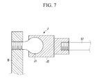
- FIG. 7 is a cross-sectional view of a floating joint for a gripper for a tailgate according to the present invention.
- FIG. 8 is a cross-sectional view of a rotation pad for a gripper for a tailgate according to the present invention.
- FIG. 9 is a perspective view of a gripper for a tailgate according to the present invention when clamped to the tailgate.
- the present invention features a gripper for a tailgate, that includes a frame, a first clamping unit, a vertical movement means, second and third clamping units and a horizontal movement means.
- the first clamping unit includes a first clamper.
- the first clamping unit is configured so the first clamper regulates an upper portion of a tailgate.
- the vertical movement means is operably coupled to the frame and the first clamping unit.
- the vertical movement means is configured to move the first clamping unit in a vertical direction so that the first clamper regulates the upper portion of a tailgate.
- the second and third clamping units are configured so as to be respectively moved in a horizontal direction at both lower sides of the frame through each sliding bracket of the horizontal movement means so the second and third clampers regulate lower sides of the tailgate by second and third clamping cylinders through second and third locators.
- the horizontal movement means is operably coupled to the frame and respectively to the second and third clamping units. Also, the horizontal movement means is configured so as to cause the second and third clamping units to move in a horizontal direction so that the second an third clampers regulate lower sides of the tailgate.
- the frame at a lower portion and rear surface thereof includes a tool mounting portion which is configured for mounting to a tool changer of a robot.
- the vertical movement means includes a sliding bracket, a guide rail and an electric cylinder, where the sliding bracket moves along the guide rail in the vertical direction by the electric cylinder disposed in an upper portion of the frame.
- the first clamping unit is arranged so as to be moved in a vertical direction on an upper portion of the frame through the sliding bracket of the vertical movement means to make a first clamper regulate an upper middle of a tailgate by the first clamping cylinder through the first locator.
- the horizontal movement means includes a plurality of sliding bracket, a plurality of guide rails and a plurality of electric cylinders, where the horizontal movement means is arranged so each sliding bracket is moved in a horizontal direction along each guide rail by each electric cylinder at both lower sides of the frame.
- the second and third clamping units are arranged so as to be respectively moved in a horizontal direction at both lower sides of the frame through each sliding bracket of both horizontal movement means so the second and third clampers regulate lower sides of the tailgate by second and third clamping cylinders through second and third locators.
- FIGS. 3-6 there is shown a gripper 20 for a tailgate (hereinafter “tailgate gripper”) according to particular aspects/embodiments of the present invention.
- tailgate gripper a gripper 20 for a tailgate
- FIG. 3 there is shown a rear view of a door showing clamping point(s) for a tailgate gripper 20 according to the present invention
- FIG. 4 provides a perspective view of a tailgate gripper according to the present invention when mounts to, or installed on a robot.
- FIG. 5 and FIG. 6 are perspective views of a tailgate gripper according to the present invention such as that shown in FIG. 4 . Reference should be made to one of FIGS. 3-6 in the following discussion.
- a tailgate 9 for use with a tailgate gripper 20 for a tailgate 9 of the present invention includes an upper clamping point P 1 and lower clamping points P 2 respectively corresponding to the upper center and both lower sides of an opening 13 of an inner panel 11 on a rear surface of a tailgate 9 .
- the tailgate gripper 20 is configured so as to include a mating or mounting structure at a rear side of the frame 21 that is configurable so as to be attached to a tool changer 15 that is arranged at the front end of an arm 3 of a robot 1 .
- the tailgate gripper 20 includes a basic frame 21 , a first upper side clamping unit 30 corresponding to the upper clamping point P 1 , and second and third lower side clamping units 40 corresponding to the lower clamping points P 2 .
- the first clamping unit 30 is mounted on the upper portion of the frame 21 through vertical movement means 50
- the second and third clamping units 40 are respectively mounted on both lower sides of the frame 21 through horizontal movement means 60 .
- the frame 21 is configured so as to include a tool mounting portion 23 at a lower side of a rear surface of the frame 21 .
- the tool changer 15 of the robot 1 is mounted on the tool mounting portion 23 .
- the vertical movement means 50 is disposed at an upper portion of the frame 21 so as to move a sliding bracket along a guide rail in a vertical direction by an electric cylinder, and includes a vertical guide rail 51 that is mounted on the frame 21 in a vertical direction.
- the vertical sliding bracket 53 is disposed on the vertical guide rail 51 through a slider (S) to be slidable in a vertical direction.
- a vertical electric cylinder 55 is disposed at one side of the vertical guide rail 51 in a vertical direction of the frame 21 .
- the front end of an operating rod 57 of the vertical electric cylinder 55 is connected to the vertical sliding bracket 53 through a connecting bracket (B).
- the front end of the operating rod 57 of the vertical electric cylinder 55 is connected to the connecting bracket (B) through a floating joint (J) so as to eliminate a load applied to the vertical electric cylinder 55 in a case that the operating rod 57 of the vertical electric cylinder 55 is not parallel to the vertical guide rail 51 .
- Such a floating joint (J) is arranged so a rotation ball J 1 fixed on the connecting bracket (B), is rotatably inserted into a joint housing J 2 mounting on the front end of the operating rod 57 of the vertical electric cylinder 55 .
- the first clamping unit 30 is disposed so as to be moved in a vertical direction of the frame 21 at the vertical sliding bracket 53 of the vertical movement means 50 .
- the first clamper C 1 regulates the upper clamping point P 1 of the upper center part of the tailgate 9 against the first locator L 1 by the first clamping cylinder CY 1 .
- the first locator L 1 is extended in a forward direction of the vertical sliding bracket 53 , and one end of the first clamping cylinder CY 1 is connected to a lower side of the first locator L 1 through a hinge.
- first clamper C 1 is connected to a front end portion of the first locator L 1 by a hinge, and the other side of the first clamper C 1 is connected to the front end of a rod (R) of the first clamping cylinder CY 1 by a hinge.
- a rotation pad 71 where a swivel ball 73 is arranged so as to be rotatable in a predetermined range is formed at a regulation surface of the first locator L 1 and the first clamper C 1 .
- the upper clamping cylinder CY 1 is a hydraulic cylinder such as those known to those skilled in the art that is operated using a pressurized fluid.
- the upper clamping cylinder CY 1 is a pneumatic cylinder that uses pressurized air or other gas as the operational pressure for operating the cylinder.
- both sides of the horizontal movement means 60 are arranged at both lower sides of the frame 21 so as to move in a horizontal direction along a guide rail of a sliding bracket by the electric cylinder.
- the horizontal direction guide rails 61 are disposed at both lower sides of the frame 21 in a horizontal direction of the horizontal movement means 60 .
- a horizontal direction sliding bracket 63 is respectively mounted on each horizontal direction guide rail 61 to slide in an horizontal direction through a slider (S).
- horizontal direction electric cylinders 65 are respectively disposed at an upper side and a lower side of a lower portion of the frame 21 between the horizontal direction guide rails 61 in a horizontal direction.
- the front end of each operating rod 67 of the horizontal direction electric cylinder 65 is connected to each horizontal direction sliding bracket 63 through a connecting bracket (B).
- each operating rod 67 of each horizontal direction electric cylinder 65 is connected to the connecting bracket (B) through the floating joint (J), and eliminates a load applied to each horizontal direction electric cylinder 65 when an operating rod 67 of each horizontal direction electric cylinder 65 is not parallel to each horizontal direction guide rail 61 .
- the second and third clamping units 40 are respectively arranged on the horizontal direction sliding bracket 63 at both sides of the horizontal movement means 60 so as to be moved at both lower sides of the frame 21 in a horizontal direction.
- the second and third clamper C 2 and C 3 respectively regulate a lower clamping point(s) P 2 of both lower sides of the tailgate 9 against the second and third locator L 2 and L 3 by the second and third clamping cylinder CY 2 and CY 3 .
- the second and third locators L 2 and L 3 are extended in a forward direction of each horizontal direction sliding bracket 63 .
- each of the second and third clamping cylinders CY 2 and CY 3 is respectively connected to one side of the second and third locators L 2 and L 3 through a hinge.
- each side of the second and third clampers C 2 and C 3 is respectively connected to a front end portion of the second and third locators L 2 and L 3 through a hinge, and the other side thereof is connected to a front end of a rod (R) of the second and third clamping cylinders CY 2 and CY 3 , respectively, through a hinge.
- each of the second and third clamping cylinders CY 2 , CY 3 1 is a hydraulic cylinder such as those known to those skilled in the art that is operated using a pressurized fluid.
- each of the second and third clamping cylinders CY 2 , CY 3 is a pneumatic cylinder that uses pressurized air or other gas as the medium for operating the cylinder.
- the rotation pad 71 is respectively disposed at a regulation surface of the first locator L 1 and the first clamper C 1 , and a swivel ball 73 that is rotatable within about 12° degrees is applied to the rotation pad 71 so as to correspond to different angles of the regulation surface.
- the first clamper C 1 and the first locator L 1 regulate the upper clamping point P 1 of the inner panel 11 of the tailgate 9 by the first clamping cylinder CY 1 of the first clamping unit 30
- the second and third clampers C 2 and C 3 and the second and third locator L 2 and L 3 regulate both lower clamping points P 2 of the inner panel 11 of the tailgate 9 by the second and third clamping cylinders CY 2 and CY 3 of the second and third clamping units 40 .
- the tailgate gripper 20 operates both horizontal direction electric cylinders 65 to adjust the distance between the second and third clamping units 40 so as to correspond to the position of the lower clamping points P 2 in a case that the tailgate 9 is changed to a different size. Also, the vertical electric cylinder 55 is operated to adjust the vertical direction of the first clamping unit 30 with respect to the second and third clamping units 40 so as to correspond to heights of a new upper clamping point P 1 and new lower clamping points P 2 .
Applications Claiming Priority (2)
| Application Number | Priority Date | Filing Date | Title |
|---|---|---|---|
| KR10-2009-0120099 | 2009-12-04 | ||
| KR1020090120099A KR101134965B1 (ko) | 2009-12-04 | 2009-12-04 | 테일게이트용 그리퍼 |
Publications (2)
| Publication Number | Publication Date |
|---|---|
| US20110135436A1 US20110135436A1 (en) | 2011-06-09 |
| US8408616B2 true US8408616B2 (en) | 2013-04-02 |
Family
ID=43972547
Family Applications (1)
| Application Number | Title | Priority Date | Filing Date |
|---|---|---|---|
| US12/846,981 Active 2031-02-28 US8408616B2 (en) | 2009-12-04 | 2010-07-30 | Gripper for tailgate of vehicles |
Country Status (4)
| Country | Link |
|---|---|
| US (1) | US8408616B2 (ko) |
| KR (1) | KR101134965B1 (ko) |
| CN (1) | CN102085608B (ko) |
| DE (1) | DE102010038702A1 (ko) |
Cited By (4)
| Publication number | Priority date | Publication date | Assignee | Title |
|---|---|---|---|---|
| US20150016942A1 (en) * | 2013-07-09 | 2015-01-15 | General Electric Company | System and method for lifting an electronics panel |
| US10105853B1 (en) * | 2017-10-05 | 2018-10-23 | GM Global Technology Operations LLC | Flexible robot end-effector for assembling door closure |
| US11260540B2 (en) * | 2017-03-30 | 2022-03-01 | Tyco Electronics (Shanghai) Co. Ltd. | Automatic pick-up equipment |
| US11458638B2 (en) * | 2017-12-25 | 2022-10-04 | Shenyang Institute Of Automation, Chinese Academy Of Sciences | Robot multi-degree-of-freedom clamper |
Families Citing this family (23)
| Publication number | Priority date | Publication date | Assignee | Title |
|---|---|---|---|---|
| KR101172308B1 (ko) * | 2010-09-06 | 2012-08-07 | 현대자동차주식회사 | 도어용 그리퍼 |
| CN102390007B (zh) * | 2011-08-02 | 2015-10-28 | 奇瑞汽车股份有限公司 | 一种行李舱盖装配辅具 |
| KR101326833B1 (ko) * | 2011-12-06 | 2013-11-07 | 현대자동차 주식회사 | 다차종 사이드 공용 지그 |
| CN103273441B (zh) * | 2013-05-23 | 2016-05-25 | 中原内配集团股份有限公司 | 一种热喷涂工装 |
| DE102013016820B4 (de) | 2013-10-10 | 2017-10-19 | Daimler Ag | Handhabungssystem für unterschiedliche Bauteilvarianten und Verfahren zum Betreiben eines Handhabungssystems |
| US9610675B2 (en) * | 2013-11-06 | 2017-04-04 | Nu-Way Industries, Inc | Clamp system for welding applications |
| CN104985474B (zh) * | 2015-08-05 | 2017-08-29 | 伟本智能机电(上海)股份有限公司 | 一种下料机械手 |
| KR101693506B1 (ko) * | 2016-06-03 | 2017-01-06 | 심우영 | 그리핑 장치 및 이를 구비하는 조립 시스템 |
| CN106112939A (zh) * | 2016-08-25 | 2016-11-16 | 陈红玲 | 电动墙板翻转车夹紧翻转装置 |
| CN106314598B (zh) * | 2016-08-31 | 2018-08-28 | 常熟明辉焊接器材有限公司 | 用于汽车装配的承接装置 |
| CN106335570B (zh) * | 2016-08-31 | 2018-10-09 | 常熟明辉焊接器材有限公司 | 用于铰链装配的支架 |
| CN106379445B (zh) * | 2016-08-31 | 2018-07-13 | 常熟明辉焊接器材有限公司 | 汽车铰链装配框架 |
| CN106347524B (zh) * | 2016-08-31 | 2018-08-28 | 常熟明辉焊接器材有限公司 | 铰链装配连接装置 |
| FR3056131B1 (fr) * | 2016-09-16 | 2019-04-19 | Peugeot Citroen Automobiles Sa | Procede et installation de soudage d’elements de carosserie automobile |
| JP6808181B2 (ja) | 2017-05-18 | 2021-01-06 | Smc株式会社 | ワーク保持装置 |
| CN107363854B (zh) * | 2017-08-24 | 2024-03-15 | 广东利元亨智能装备有限公司 | 一种伸缩式的机械抓手 |
| CN109774822B (zh) * | 2018-12-20 | 2020-08-07 | 东风汽车集团有限公司 | 一种用于车身侧围输送的定位传导装置及其使用方法 |
| CN112573182B (zh) * | 2019-09-27 | 2022-05-27 | 深圳华大智造科技股份有限公司 | 抓取转移装置及生化分析仪 |
| CN112710270A (zh) * | 2020-12-24 | 2021-04-27 | 一汽奔腾轿车有限公司 | 一种车门零件环境实验用的柔性工装 |
| CN114406965B (zh) * | 2021-12-08 | 2023-06-30 | 东莞市超业精密设备有限公司 | 一种电池封装的翻盖夹具 |
| CN116215462B (zh) * | 2023-03-06 | 2023-08-15 | 长春大正博凯汽车设备有限公司 | 一种后盖抓持一体式装具 |
| CN116787103B (zh) * | 2023-08-28 | 2023-11-10 | 巨硕精密机械(常熟)有限公司 | 一种车尾门铰链高精度调整装置 |
| CN117140559B (zh) * | 2023-10-30 | 2024-01-26 | 启东市云鹏玻璃机械有限公司 | 一种用于玻璃加工的间距可调机械手 |
Citations (9)
| Publication number | Priority date | Publication date | Assignee | Title |
|---|---|---|---|---|
| US4453873A (en) * | 1982-03-11 | 1984-06-12 | Ezio Curti | Automatic supporting plate loader |
| US5127695A (en) * | 1989-06-16 | 1992-07-07 | Hoogovens Groep Bv | Apparatus for manipulating a pallet |
| US5271651A (en) * | 1988-11-14 | 1993-12-21 | John A. Blatt | Work holder support apparatus |
| JPH11188553A (ja) | 1997-12-24 | 1999-07-13 | Honda Motor Co Ltd | ワーク保持装置 |
| US6273483B1 (en) * | 1996-03-28 | 2001-08-14 | Mcmaster University | Three orthogonal directions movable fingers for holding and/or manipulating a three-dimensional object |
| US6722842B1 (en) * | 1998-01-13 | 2004-04-20 | Btm Corporation | End arm manipulator |
| US7100955B2 (en) * | 2002-09-03 | 2006-09-05 | Nissan Motor Co., Ltd. | General purpose hand for multiaxis manipulator |
| US7267383B2 (en) * | 2004-05-28 | 2007-09-11 | Bilsing Automation Gmbh | Method and support arrangement for fixing and demounting a gripper tool to the transverse beam of a transfer press |
| KR20090053078A (ko) | 2007-11-22 | 2009-05-27 | 현대자동차주식회사 | 도어 패널 이송 그립퍼 |
Family Cites Families (4)
| Publication number | Priority date | Publication date | Assignee | Title |
|---|---|---|---|---|
| CA2324820C (en) * | 2000-10-30 | 2004-05-04 | Clayton Dean Babchuk | Workpiece support apparatus |
| CN100427262C (zh) * | 2007-05-29 | 2008-10-22 | 东华大学 | 一种柔性可重构的汽车焊装夹具 |
| KR20090003482U (ko) * | 2007-10-10 | 2009-04-15 | 대우조선해양 주식회사 | 배관 고정용 지그 |
| CN201214177Y (zh) * | 2008-07-08 | 2009-04-01 | 中国北车集团大同电力机车有限责任公司 | 司机室组焊胎 |
-
2009
- 2009-12-04 KR KR1020090120099A patent/KR101134965B1/ko active IP Right Grant
-
2010
- 2010-07-30 US US12/846,981 patent/US8408616B2/en active Active
- 2010-07-30 CN CN201010502875.3A patent/CN102085608B/zh active Active
- 2010-07-30 DE DE102010038702A patent/DE102010038702A1/de active Pending
Patent Citations (9)
| Publication number | Priority date | Publication date | Assignee | Title |
|---|---|---|---|---|
| US4453873A (en) * | 1982-03-11 | 1984-06-12 | Ezio Curti | Automatic supporting plate loader |
| US5271651A (en) * | 1988-11-14 | 1993-12-21 | John A. Blatt | Work holder support apparatus |
| US5127695A (en) * | 1989-06-16 | 1992-07-07 | Hoogovens Groep Bv | Apparatus for manipulating a pallet |
| US6273483B1 (en) * | 1996-03-28 | 2001-08-14 | Mcmaster University | Three orthogonal directions movable fingers for holding and/or manipulating a three-dimensional object |
| JPH11188553A (ja) | 1997-12-24 | 1999-07-13 | Honda Motor Co Ltd | ワーク保持装置 |
| US6722842B1 (en) * | 1998-01-13 | 2004-04-20 | Btm Corporation | End arm manipulator |
| US7100955B2 (en) * | 2002-09-03 | 2006-09-05 | Nissan Motor Co., Ltd. | General purpose hand for multiaxis manipulator |
| US7267383B2 (en) * | 2004-05-28 | 2007-09-11 | Bilsing Automation Gmbh | Method and support arrangement for fixing and demounting a gripper tool to the transverse beam of a transfer press |
| KR20090053078A (ko) | 2007-11-22 | 2009-05-27 | 현대자동차주식회사 | 도어 패널 이송 그립퍼 |
Cited By (5)
| Publication number | Priority date | Publication date | Assignee | Title |
|---|---|---|---|---|
| US20150016942A1 (en) * | 2013-07-09 | 2015-01-15 | General Electric Company | System and method for lifting an electronics panel |
| US9302888B2 (en) * | 2013-07-09 | 2016-04-05 | General Electric Company | System and method for lifting an electronics panel |
| US11260540B2 (en) * | 2017-03-30 | 2022-03-01 | Tyco Electronics (Shanghai) Co. Ltd. | Automatic pick-up equipment |
| US10105853B1 (en) * | 2017-10-05 | 2018-10-23 | GM Global Technology Operations LLC | Flexible robot end-effector for assembling door closure |
| US11458638B2 (en) * | 2017-12-25 | 2022-10-04 | Shenyang Institute Of Automation, Chinese Academy Of Sciences | Robot multi-degree-of-freedom clamper |
Also Published As
| Publication number | Publication date |
|---|---|
| CN102085608B (zh) | 2015-02-11 |
| KR20110063149A (ko) | 2011-06-10 |
| KR101134965B1 (ko) | 2012-04-09 |
| US20110135436A1 (en) | 2011-06-09 |
| DE102010038702A1 (de) | 2011-06-09 |
| CN102085608A (zh) | 2011-06-08 |
Similar Documents
| Publication | Publication Date | Title |
|---|---|---|
| US8408616B2 (en) | Gripper for tailgate of vehicles | |
| US8256811B2 (en) | Door gripper for a vehicle and manufacturing methods using such a door gripper | |
| US8485575B2 (en) | Gripper for door of vehicle | |
| CN103042376B (zh) | 车门铰链用安装设备及安装方法 | |
| US20050008469A1 (en) | Apparatus for manipulating a vehicle body panel | |
| US9849580B2 (en) | Door separation device that is used for multi kinds of vehicles | |
| US20100252973A1 (en) | Clamping device for holding and clamping components | |
| CN108609071B (zh) | 用于车身组装系统的预装配单元 | |
| CN101244564A (zh) | 一种用于遥控焊接机器人的工具快速转换接口 | |
| CN1883840A (zh) | 小半径弯管机四连杆蛇形管夹紧装置 | |
| KR101405231B1 (ko) | 트렁크 리드 및 테일 게이트 공용 증타 지그장치 | |
| CN205271282U (zh) | 一种汽车车门内板焊接夹紧机构 | |
| KR101438631B1 (ko) | 차량용 패널 지그장치의 각도 조절 클램프 | |
| US11186228B2 (en) | Storage device for a vehicle cab | |
| US10899404B2 (en) | Door hoist apparatuses including multi-bar actuation assemblies with suction end effectors and methods using the same | |
| AU2014225233B2 (en) | Drop-down utility rack for vehicles | |
| CN210554102U (zh) | 滑移车门及车辆 | |
| EP2229336B1 (en) | Lifting mechanism and transport vehicle equipped with such mechanism | |
| CN110711990B (zh) | 车门铰链安装机构 | |
| JP6040909B2 (ja) | シート搭載装置及びシート搭載方法 | |
| CN105689949A (zh) | 一种可转动的自动伸缩薄板件夹具 | |
| CN216066164U (zh) | 用于汽车冲压件焊接的夹具 | |
| CN214828759U (zh) | 一种叉车用液压驱动旋转夹抱搬运装置 | |
| CN209986464U (zh) | 汽车白车身焊装摆动切换机构 | |
| CN209797290U (zh) | 以相同液体的压强平衡结构的倾翻保护施工的机械驾驶室 |
Legal Events
| Date | Code | Title | Description |
|---|---|---|---|
| AS | Assignment |
Owner name: KIA MOTORS CORPORATION, KOREA, REPUBLIC OF Free format text: ASSIGNMENT OF ASSIGNORS INTEREST;ASSIGNORS:YEUM, JUNG WHAN;HWANG, DOO IL;REEL/FRAME:024765/0301 Effective date: 20100723 Owner name: HYUNDAI MOTOR COMPANY, KOREA, REPUBLIC OF Free format text: ASSIGNMENT OF ASSIGNORS INTEREST;ASSIGNORS:YEUM, JUNG WHAN;HWANG, DOO IL;REEL/FRAME:024765/0301 Effective date: 20100723 |
|
| FEPP | Fee payment procedure |
Free format text: PAYOR NUMBER ASSIGNED (ORIGINAL EVENT CODE: ASPN); ENTITY STATUS OF PATENT OWNER: LARGE ENTITY |
|
| STCF | Information on status: patent grant |
Free format text: PATENTED CASE |
|
| FEPP | Fee payment procedure |
Free format text: PAYER NUMBER DE-ASSIGNED (ORIGINAL EVENT CODE: RMPN); ENTITY STATUS OF PATENT OWNER: LARGE ENTITY Free format text: PAYOR NUMBER ASSIGNED (ORIGINAL EVENT CODE: ASPN); ENTITY STATUS OF PATENT OWNER: LARGE ENTITY |
|
| FPAY | Fee payment |
Year of fee payment: 4 |
|
| MAFP | Maintenance fee payment |
Free format text: PAYMENT OF MAINTENANCE FEE, 8TH YEAR, LARGE ENTITY (ORIGINAL EVENT CODE: M1552); ENTITY STATUS OF PATENT OWNER: LARGE ENTITY Year of fee payment: 8 |