US8330809B2 - Vision system with software control for detecting dirt and other imperfections on egg surfaces - Google Patents
Vision system with software control for detecting dirt and other imperfections on egg surfaces Download PDFInfo
- Publication number
- US8330809B2 US8330809B2 US12/365,364 US36536409A US8330809B2 US 8330809 B2 US8330809 B2 US 8330809B2 US 36536409 A US36536409 A US 36536409A US 8330809 B2 US8330809 B2 US 8330809B2
- Authority
- US
- United States
- Prior art keywords
- enclosure
- eggs
- cameras
- vision system
- camera
- Prior art date
- Legal status (The legal status is an assumption and is not a legal conclusion. Google has not performed a legal analysis and makes no representation as to the accuracy of the status listed.)
- Expired - Fee Related, expires
Links
Images


Classifications
-
- G—PHYSICS
- G01—MEASURING; TESTING
- G01N—INVESTIGATING OR ANALYSING MATERIALS BY DETERMINING THEIR CHEMICAL OR PHYSICAL PROPERTIES
- G01N21/00—Investigating or analysing materials by the use of optical means, i.e. using sub-millimetre waves, infrared, visible or ultraviolet light
- G01N21/84—Systems specially adapted for particular applications
- G01N21/88—Investigating the presence of flaws or contamination
- G01N21/8806—Specially adapted optical and illumination features
-
- A—HUMAN NECESSITIES
- A01—AGRICULTURE; FORESTRY; ANIMAL HUSBANDRY; HUNTING; TRAPPING; FISHING
- A01K—ANIMAL HUSBANDRY; CARE OF BIRDS, FISHES, INSECTS; FISHING; REARING OR BREEDING ANIMALS, NOT OTHERWISE PROVIDED FOR; NEW BREEDS OF ANIMALS
- A01K43/00—Testing, sorting or cleaning eggs ; Conveying devices ; Pick-up devices
- A01K43/04—Grading eggs
-
- G—PHYSICS
- G01—MEASURING; TESTING
- G01N—INVESTIGATING OR ANALYSING MATERIALS BY DETERMINING THEIR CHEMICAL OR PHYSICAL PROPERTIES
- G01N21/00—Investigating or analysing materials by the use of optical means, i.e. using sub-millimetre waves, infrared, visible or ultraviolet light
- G01N21/84—Systems specially adapted for particular applications
- G01N21/88—Investigating the presence of flaws or contamination
- G01N21/95—Investigating the presence of flaws or contamination characterised by the material or shape of the object to be examined
- G01N21/951—Balls
-
- G—PHYSICS
- G01—MEASURING; TESTING
- G01N—INVESTIGATING OR ANALYSING MATERIALS BY DETERMINING THEIR CHEMICAL OR PHYSICAL PROPERTIES
- G01N33/00—Investigating or analysing materials by specific methods not covered by groups G01N1/00 - G01N31/00
- G01N33/02—Food
- G01N33/08—Eggs, e.g. by candling
-
- G—PHYSICS
- G01—MEASURING; TESTING
- G01N—INVESTIGATING OR ANALYSING MATERIALS BY DETERMINING THEIR CHEMICAL OR PHYSICAL PROPERTIES
- G01N21/00—Investigating or analysing materials by the use of optical means, i.e. using sub-millimetre waves, infrared, visible or ultraviolet light
- G01N21/84—Systems specially adapted for particular applications
- G01N2021/845—Objects on a conveyor
Definitions
- the present invention teaches a vision system incorporating software control for detecting defects on both brown and white eggs, as well as the ability to detect multiple shades of brown eggs.
- the present invention employs any number of pairs of imaging cameras, such as in particular Ethernet cameras, these being grouped within a three dimensional enclosure that isolates all controlling electrical equipment in a separate sealed section of the unit.
- the unit also includes one or more illuminating elements, as well as a curved, arcuate or otherwise non-linear shaped reflector or diffuser element, for redirecting and equally distributing the light generated from the illuminating elements in any of a focused, magnified and evenly distributed fashion within the interior of the unit.
- the vision system provides, in one non-limiting application, for non-invasive inspection of eggs and in which, by virtue of the ability of the illuminating elements and curved diffuser to uniformly illuminate the area within (as well as optionally below) the unit, this precluding the instance of shadows and other undesirable dark spots, thereby providing for more accurate inspection and detection of egg shades and blemishes.
- Egg inspection apparatuses are well known in the relevant art. Such apparatuses are often employed in conjunction with varying types of egg processing and transfer equipment, such as conveyors. Typical applications of such devices include the non-invasive inspection of eggs and in order to classify the same, such as by color, size and the like, as well as in detecting unacceptable blemishes associated with such eggs.
- a device for inspecting objects with a spherical surface is set forth in U.S. Pat. No. 7,474,392, to Van Soest, and which a three dimensional box shaped enclosure includes a plurality of upper-most positioned strip lights which illuminate through a matt transparent (e.g. milky like) diffuser plate, and which functions as a top of the box enclosure.
- a series of four interconnected side and end walls each further exhibit a mirroring inner surface exhibiting a high coefficient of reflection, this causing a constantly recurring light source to be produced for equally illuminating a plurality of objects placed upon a conveyor in communication with an open bottom of the box.
- One or more cameras are arranged above the conveyors approximate the top inner side walls of the box for observing the objects on the conveyor.
- the present invention discloses a vision system incorporated into an item of egg handling equipment, the system incorporating software control for detecting at least one of color shades and defects on both brown and white eggs.
- An enclosure incorporates a plurality of high resolution producing cameras (such as Ethernet cameras), these communicating with a gigabit (Ethernet) switch by cable to a remote mounted vision PC system.
- Ethernet gigabit
- a diffuser (also termed a reflective or distribution element) is mounted along an open facing bottom of the enclosure.
- the diffuser exhibits a curved, arcuate or otherwise non-linear shape, such as including but not limited to a parabolic or like shape, and facilitates uniform lighting throughout an open interior of the enclosure associated with the cameras.
- a plurality of light producing/illuminating elements are arranged above the diffuser and, in combination with the cameras are operable to produce multiple, high resolution images of each of a plurality of eggs continuously transported along the associated egg handling equipment, such as for classifying types of defects that are allowable and those that must be rejected, as well as assisting in the segregating of the eggs into more consistent shaded groups for eventual packaging.
- the cameras can be grouped in any fashion, such as in pairs, such that each camera views a plurality of eggs at a given moment.
- the associated egg handling equipment can also rotate the egg during the sequence of images taken by the cameras.
- the illuminating elements are further provided by such as high frequency fluorescent bulbs located along the unit interior. The lighting passes through the customized parabolic, or other non-linear/curved diffuser mounted along an open facing bottom of the unit, for facilitating uniform lighting throughout the unit as well as along the surface area of the conveyor upon which are supported the eggs or other articles to be inspected.
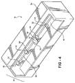
- FIG. 1 is a perspective and assembled illustration vision system according to the present invention and exhibiting the three dimensional enclosure, grouped pairs of imaging cameras, fluorescent light tubes and downwardly facing parabolic reflector;
- FIG. 2 is a rotated perspective of the vision system and with a selected three dimensional enclosure defining side panel removed in order to better illustrate the arrangement of the cameras, lighting, and parabolic reflector;
- FIG. 3 is a further rotated and partially exploded perspective of the vision system
- FIG. 4 is a rotated and further assembled top perspective of the vision system shown in FIG. 1 ;
- FIG. 5 is slightly rotated exploded perspective in comparison to that shown in FIG. 3 ;
- FIG. 5A is a partial illustration of a modified and dome shaped diffuser element according to a further variant
- FIG. 5B illustrates the logarithmic function associated with a cross section of the dome shape diffuser and including parabolic components extending in opposite fashion from the top center lie, linear components extending from end points of the parabolic components, and logarithmic components extending from end points of the linear components to side extending edges of the diffuser;
- FIG. 6 is a perspective illustration of the vision system mounted to an existing piece of egg handling equipment, and such as including an egg conveyor which is mounted a distance below an overhead suspended vision system, such further illustrating an Ethernet cable extending from the three dimensional unit and connecting to a vision PC at a remote location.
- a vision system 10 is disclosed, such as for detecting defects on both brown and white eggs, as well as the ability to detect multiple shades of brown eggs.
- the vision system 10 incorporates machine vision inspection technology, such further understood to include any suitable processor or hardware based support and exhibiting the ability to interface with associated computer related software products, as well as a custom designed element or diffuser (e.g. parabolic and dome shaped as in the examples illustrated) component built into the system for facilitating uniform lighting throughout the assembly.
- FIG. 6 a perspective illustration is shown of the vision system mounted to an existing piece of egg handling equipment, collectively referenced at 12 , and by example illustrating an egg orienting and accumulating system used in transporting large numbers of eggs (see at 13 ), such as from and along a central conveying belt into single file lanes, and for subsequent transfer onto spool bars for delivery to such as another conveyor, egg washer application or the like.
- an egg orienting and accumulating system used in transporting large numbers of eggs (see at 13 ), such as from and along a central conveying belt into single file lanes, and for subsequent transfer onto spool bars for delivery to such as another conveyor, egg washer application or the like.
- the various features associated with the egg conveying/handling equipment 12 are not further referenced or described.
- an Ethernet cable extending from the three dimensional unit 10 , and which is the focus of the present invention, and connecting to a vision PC 16 at a remote location, the functioning of which being described below in further detail.
- the vision system incorporates an inspection sub-system the technology for which including adequate hardware and processor components (generally referenced as being included within PC 16 ) and in order to provide the suitable operating protocol for establishing the inspection parameters of the eggs 13 or other transported objects, such parameters again understood as including shading, determining the existence of spots/blemishes as well as the ability to identify other potential metrics and/or imperfections.
- Ethernet refers to a family of frame-based computer networking technologies for local area networks (LANs).
- the name comes from the physical concept of the “ether” and defines a number of wiring and signaling standards, through means of network access of a Media Access Control (MAC)/Data Link Layer, and a common addressing format.
- MAC Media Access Control
- Data Link Layer a common addressing format.
- Ethernet stations communicate by sending each other data packets, these consisting of individual blocks of data that are individually sent and delivered.
- each Ethernet station is given a single 48-bit address, which is used both to specify the destination and the source of each data packet.
- the disclosed embodiments includes pairs of Ethernet communicable digital cameras which are grouped within the three dimensional enclosure defining the vision system 10 , and as further referenced by individual pairs of opposing arrayed cameras 18 , 20 and 22 .
- the individual groupings of the cameras e.g. again at 18 , 20 and 22
- any plurality of cameras including a single camera or other off number of cameras, can be suitably employed in any variation according to the present inventions and for functioning in the manner described and claimed herein.
- Ethernet communicable cameras are disclosed in one preferred embodiment, other potential imaging devices, including other acceptable versions of digital cameras operating under different communication platforms, can also be utilized in the incorporation of a modified vision system such perhaps not requiring an Ethernet connection, and without departing from the scope of the invention.
- an Ethernet cable 14 can be substituted with other cabling or, in certain instances, wireless connectivity established between various (paired) cameras with associated processor controls, incorporated into the cameras or associated components.
- each camera can provide a plurality of individual images (such as up to ten or more) per egg.
- the associated egg handling equipment (again FIG. 6 ), can also rotate the egg during the sequence of images taken by each of the paired camera(s) 18 , 20 and 22 .
- the opposing and angled arrangement of the camera pairs 18 , 20 and 22 , illustrated in FIGS. 1-5 is further suggestive of one possible arrangement of cameras, it further being understood that any reconfiguration of such cameras is contemplated, and such that either single or multiple (three or more) cameras can be adapted into a desired arrangement and, in cooperation with the performance aspects of the associated egg handling equipment, can provide both a desired number of images and associated degree of resolution of multiple items to be imaged (e.g. eggs).
- a subset and sealed enclosure 24 is provided separately from a frame constructed and generally interiorly open and adjoining enclosure, generally defined at 26 .
- the sealed enclosure 24 isolates all controlling electrical equipment (see as referenced at 28 in the partially stripped away view of FIG. 2 and exploded illustrations of FIGS. 3 and 5 ) in a separate sealed section of the overall assembly 10 .
- the open framed section 26 of the assembly 10 includes a plurality of angled mounting brackets associated with each of the pairs of offset cameras, see as shown at 30 , 32 and 34 associated with camera pairs 18 , 20 and 22 , these mounting the camera pairs such as to surfaces of the sealed electrical containing section 24 .
- a series of frames, braces, and end pieces are illustrated and which are provided for constructing a generally rectangular shaped and open interior three dimensional space, within which the camera pairs are mounted to array in a selected and downwardly angled arrangement.
- Unit lighting is provided by any plurality of illuminating elements, and such as which are represented by clear white, high frequency fluorescent bulbs or ballast tubes, referenced as a pair at 36 and 38 , this further understood to include such as the provision of any plurality of lighting elements, such as four, six, eight, ten or more fluorescent tubes (in one example each of which being 48′′ in length apiece) and arranged in spaced and widthwise extending fashion, these utilized for lighting and located along such as an intermediate interior or a bottom facing location of the unit assembly 10 . It is further envisioned and understood that the fluorescent bulbs can be substituted by other appropriate lighting elements or sources these including, without limitation, such as L.E.D. (light emitting diode), as well as incandescent or other illuminating elements. Other lighting options include such as employing lasers, and other potential lighting sources can also be incorporated into the assembly 10 .
- any plurality of lighting elements such as which are represented by clear white, high frequency fluorescent bulbs or ballast tubes, referenced as a pair at 36 and 38
- the illumination provided by the illuminating elements passes through a customized non-linear shaped (including arcuate or curved) element, or diffuser, see at 40 , and which is mounted along an open facing bottom of the framed and open unit section 26 , for facilitating uniform lighting throughout the unit assembly.
- a customized non-linear shaped element, or diffuser see at 40 , and which is mounted along an open facing bottom of the framed and open unit section 26 , for facilitating uniform lighting throughout the unit assembly.
- the configuration of the diffuser element (this term also intended to include any form of light distribution or reflection element the properties of which capable of being separately or concurrently designed into the element 40 ) in the illustrated embodiment exhibits a pseudo-parabolic shaped diffuser 40 .
- the reflecting or diffusing capabilities associated with a parabolic shape typically operate to concentrate light rays (such as generated by the illuminating elements) to a common focal point.
- the construction of the diffuser as contemplated herein is intended to multiply the focal points to the point of infinity, and so that an even and consistent image pattern is provided both within the three dimensional interior of the unit when the element 40 operates as a reflector component, as well as beneath the unit in a diffusing capacity, and such as along the area upon which the separate conveyor (see as shown in FIG. 6 ) transports the eggs or other plurality of objects to be inspected.
- the features of the reflector/diffuser 40 can further be reconfigured such that it provides any desired degree of focusing and magnification, either additionally or alternative to the objective of even distribution of illumination.
- the present invention further contemplates the provision of a non-linear element exhibiting any type of curvature or arc, such as shaped according to any mathematical or logarithmic formula for establishing a non-linear surface area, and which facilitates the focusing, even distribution, and/or magnification of the light generated by the illuminating element to the area existing below the unit as well as the surface of the below positioned conveyor.
- a non-linear element exhibiting any type of curvature or arc, such as shaped according to any mathematical or logarithmic formula for establishing a non-linear surface area, and which facilitates the focusing, even distribution, and/or magnification of the light generated by the illuminating element to the area existing below the unit as well as the surface of the below positioned conveyor.
- Such other shapes associated with an alternately configured diffuser element can include, in non-limiting fashion, any of an ellipsoidal, geoidal, modified circular, domed or exponentially curved shape for redirecting, according to any desired three dimensional pattern
- the diffuser can further exhibit a substantially dome shape, see at 40 ′, and which is further generally defined in more limiting three dimensional applications as a rounded vault configuration with a generally circular base.
- the dome shape associated with the element 40 ′ extends in a generally elongated and crosswise fashion similar to that shown in reference to the parabolic shaped element 40 in FIG. 5 , the dome shaped diffuser element 40 ′ similarly being shown with open section ends. That said, it is further understood that the ends of the dome shaped diffuser 40 ′ can also be enclosed to exhibit a likewise dome configuration.
- Additional features include the dome shaped element extending lengthwise and in a direction perpendicular to the transport direction of the underneath located conveyor (as again clearly shown also in the operational view of FIG. 6 and illustrated by directional arrows 42 extending in a linear direction relative to the egg transport conveyor, and relative to bi-directional arrow 44 identifying the extending direction of the dome shaped diffuser 40 ′, and which is illustrated in phantom in FIG. 6 ). Additional features include the dome shape exhibiting symmetrical a top center line 46 , from which extends first 48 and second 50 extending sides, as shown in FIG.
- parabolic shaped diffuser 40 best illustrated in FIG. 5 also includes a similar lengthwise extending top center line, from which extend first and second sides which can be constructed according to a desired mathematical/logarithmic function as will be more completely described below in reference to the dome shape diffuser.
- a cross section of the dome shaped diffuser 40 ′ is understood to be perpendicular to the center line 46 and which follows a curve in accordance with any suitable mathematical non-linear function, e.g. any formula or logarithm which results in the creation of a non-linear and three dimensional surface for assisting in the reflection or other redirection (e.g. diffusion) of light.
- suitable mathematical non-linear function e.g. any formula or logarithm which results in the creation of a non-linear and three dimensional surface for assisting in the reflection or other redirection (e.g. diffusion) of light.
- Such mathematical formulations are also understood to employ polynomials, i.e. expressions of multiple algebraic terms such as which contain different powers of the same variable.
- Such mathematical function can also be reconfigured to achieve the previously described parabolic shape, as well as any of an unlimited number of additional configurations.
- additional shapes can include any three dimensional surface exhibiting any number of sides, such as ranging from lesser numbers of defined sides establishing such as any of a range of multi-sided polygons, to significantly greater numbers of sides corresponding substantially to smoother arcuate shapes.
- such mathematical/logarithmic function is calculated from a center line starting point as shown at 46 in FIG. 5A . It is further understood that the logarithms employed can possess either the same or different mathematically generated functions applied to either of opposite sides of the center line 46 , this in order to create the desired three dimensional shaping of the diffuser surface.
- the mathematical function includes parabolic components extending in opposite fashion from the top center line 46 , and which are defined as being the extending components between top center line 46 to end points 52 and 54 .
- Succeeding linear components extend from the end points 52 and 54 of the parabolic components to further end points 56 and 58 .
- Logarithmic components extend from the end points 56 and 58 of the linear components to the side extending edges of the diffuser, these further defined by terminating points 60 and 62 .
- the illustrated arrangement of the opposite extending parabolic-linear-logarithmic sequences extending from top center line is understood to depict only one potential mathematical function and that other variations of mathematically constructed curves are also envisioned, such as which can reverse or modify the sequence described in FIG. 5B in any fashion desired, such as further to limit to a lesser number of distinct components or to vary their plurality and/or placement.
- the mathematical coefficients employed with each of the parabolic, linear and logarithmic functions are capable of being modified to vary the curvature, or to mutate, the profile shown.
- the ability to modify such functions, on either or both sides of the center line create the ability to choose coefficients which result in matching variations in pitch such as in the conveyor design.
- the same can be composed of different parts, each of which can be designed to accommodate different operating functions (such as again including variations in reflective and diffusive properties).
- the shaping (or reshaping) of the diffuser 40 or 40 ′ again is contemplated to operate in either (or potentially both) a reflective capacity, and in which the interior of the unit is equally illuminated to maximize the efficiency of the cameras, as well as in a diffusing capacity and in which the light can be focused, magnified or otherwise redirected beyond the interior of the enclosure or space located above the diffuser in a desired manner for better illuminating the area beneath the overhead mounted unit (see again FIG. 6 ) and such as specifically the conveyor upon which the eggs 13 are situated.
- the ability to establish both increased and balanced illumination of a transport conveyor renders possible the detection of defects associated with wet eggs, historically a very difficult parameter to assess given prior art imaging technologies.
- Ethernet technology is most broadly and conventionally defined as a local-area network protocol featuring a bus topology and a 10 megabit per second data transfer rate, this further originally based on the idea of computers communicating over a shared coaxial cable acting as a broadcast transmission medium.
- Ethernet stations communicate by sending each other data packets, blocks of data that are individually sent and delivered.
- data is broken into packets, each of which is transmitted using such as a CSMA/CD algorithm until it arrives at a destination and without colliding with any other packets.
- Each Ethernet station is given a single, such as 48-bit, address, which is used both to specify the destination and the source of each data packet.
- Network interface cards (NICs) or chips normally do not accept packets addressed to other Ethernet stations, and so as to avoid confusion such as between overlapping imaging cameras associated with these protocols.
- the high resolution cameras operate to produce multiple, high resolution images of each of a plurality of eggs continuously transported along the associated egg handling equipment to which the paired (or otherwise arrayed) cameras are mounted.
- This allows for establishing parameters within the associated PC 16 , and such as for detecting both varying shades of brown eggs, as well as for detecting smaller defects on both brown and white eggs.
- This in turn allows the user more flexibility in classifying the types of defects that are allowable and those that must be rejected, as well as assisting in the segregating of the eggs into more consistent shaded groups for eventual packaging.
- the software component of the vision system can be reprogrammed with other criteria or applications, and in order to process, segregate, and accept/reject eggs according to a desired application.
- Such parameters can include discerning additional and subset color effects and color varieties (and beyond strictly classifying between brown and white eggs). Additional classifications can be accomplished by observing and imaging slime effects, upon wetting the eggs, by yolk and/or albumen.
Priority Applications (1)
| Application Number | Priority Date | Filing Date | Title |
|---|---|---|---|
| US12/365,364 US8330809B2 (en) | 2008-02-04 | 2009-02-04 | Vision system with software control for detecting dirt and other imperfections on egg surfaces |
Applications Claiming Priority (2)
| Application Number | Priority Date | Filing Date | Title |
|---|---|---|---|
| US2597308P | 2008-02-04 | 2008-02-04 | |
| US12/365,364 US8330809B2 (en) | 2008-02-04 | 2009-02-04 | Vision system with software control for detecting dirt and other imperfections on egg surfaces |
Publications (2)
| Publication Number | Publication Date |
|---|---|
| US20090195648A1 US20090195648A1 (en) | 2009-08-06 |
| US8330809B2 true US8330809B2 (en) | 2012-12-11 |
Family
ID=40931264
Family Applications (1)
| Application Number | Title | Priority Date | Filing Date |
|---|---|---|---|
| US12/365,364 Expired - Fee Related US8330809B2 (en) | 2008-02-04 | 2009-02-04 | Vision system with software control for detecting dirt and other imperfections on egg surfaces |
Country Status (7)
| Country | Link |
|---|---|
| US (1) | US8330809B2 (ko) |
| EP (1) | EP2283309A1 (ko) |
| JP (1) | JP2011517340A (ko) |
| KR (1) | KR20100121638A (ko) |
| CN (1) | CN102016496A (ko) |
| BR (1) | BRPI0905951A2 (ko) |
| WO (1) | WO2009100114A1 (ko) |
Cited By (4)
| Publication number | Priority date | Publication date | Assignee | Title |
|---|---|---|---|---|
| US20130008475A1 (en) * | 2010-03-24 | 2013-01-10 | Fps Food Processing Systems, B.V. | Advanced egg breaking system |
| US20150317786A1 (en) * | 2014-05-05 | 2015-11-05 | Alcoa Inc. | Apparatus and methods for weld measurement |
| US10902281B2 (en) | 2018-03-22 | 2021-01-26 | Rota Technologies LLC | Debris detection system and method |
| WO2024034749A1 (ko) * | 2022-08-10 | 2024-02-15 | 주식회사 한밭아이오티 | 이상란 검출 서비스 시스템 |
Families Citing this family (24)
| Publication number | Priority date | Publication date | Assignee | Title |
|---|---|---|---|---|
| KR20100121638A (ko) | 2008-02-04 | 2010-11-18 | 에프피에스 푸드 프로세싱 시스템즈 비.브이. | 계란 표면 상의 오염물 및 기타 결점을 검출하기 위한 소프트웨어 컨트롤을 포함하는 비전 시스템 |
| KR101032788B1 (ko) * | 2011-03-29 | 2011-05-02 | 중앙아이엔티 주식회사 | 계란 신선도 검사 장치 |
| CA2957272C (en) | 2014-08-05 | 2023-08-01 | Makefield Llc | Dispensable unit retrieval mechanism, identification, and networked notification |
| JP7009389B2 (ja) | 2016-05-09 | 2022-01-25 | グラバンゴ コーポレイション | 環境内のコンピュータビジョン駆動型アプリケーションのためのシステムおよび方法 |
| US10282621B2 (en) | 2016-07-09 | 2019-05-07 | Grabango Co. | Remote state following device |
| US11132737B2 (en) | 2017-02-10 | 2021-09-28 | Grabango Co. | Dynamic customer checkout experience within an automated shopping environment |
| US10778906B2 (en) * | 2017-05-10 | 2020-09-15 | Grabango Co. | Series-configured camera array for efficient deployment |
| US10740742B2 (en) | 2017-06-21 | 2020-08-11 | Grabango Co. | Linked observed human activity on video to a user account |
| US20190079591A1 (en) | 2017-09-14 | 2019-03-14 | Grabango Co. | System and method for human gesture processing from video input |
| US10963704B2 (en) | 2017-10-16 | 2021-03-30 | Grabango Co. | Multiple-factor verification for vision-based systems |
| CN108248923A (zh) * | 2017-12-30 | 2018-07-06 | 吴迪 | 一种鸡蛋包装装置 |
| US11481805B2 (en) | 2018-01-03 | 2022-10-25 | Grabango Co. | Marketing and couponing in a retail environment using computer vision |
| JP6988592B2 (ja) * | 2018-03-13 | 2022-01-05 | オムロン株式会社 | 画像検査装置、画像検査方法及び画像検査プログラム |
| KR102251936B1 (ko) * | 2018-05-24 | 2021-05-14 | (주)쎄미시스코 | 챔버에서의 결함 검사 시스템 및 그 방법 |
| WO2020092450A1 (en) | 2018-10-29 | 2020-05-07 | Grabango Co. | Commerce automation for a fueling station |
| US11507933B2 (en) | 2019-03-01 | 2022-11-22 | Grabango Co. | Cashier interface for linking customers to virtual data |
| CN109781739A (zh) * | 2019-03-04 | 2019-05-21 | 杭州晶耐科光电技术有限公司 | 汽车漆面表面外观缺陷全自动检测系统及方法 |
| JP6616040B1 (ja) * | 2019-07-08 | 2019-12-04 | 西進商事株式会社 | 外観検査装置 |
| CN110793472B (zh) * | 2019-11-11 | 2021-07-27 | 桂林理工大学 | 一种基于四元数奇异值熵指标的磨削表面粗糙度检测方法 |
| CN111328738B (zh) * | 2020-02-05 | 2021-11-16 | 江苏仁康蛋业有限公司 | 一种高打发鸡蛋白液的制备系统 |
| KR20220101910A (ko) * | 2021-01-12 | 2022-07-19 | 은 식 신 | 구운계란의 파각 검출 및 추출 장치 |
| KR102431960B1 (ko) | 2021-01-15 | 2022-08-16 | 주식회사 한밭아이오티 | 계란 품질 선별기 |
| KR102283869B1 (ko) | 2021-01-15 | 2021-08-02 | 주식회사 한밭아이오티 | 계란 품질 자동검사 시스템 |
| KR102625717B1 (ko) | 2023-06-23 | 2024-01-17 | (주)아이프리즘 | 비전 계란 선별 시스템 |
Citations (46)
| Publication number | Priority date | Publication date | Assignee | Title |
|---|---|---|---|---|
| US2731146A (en) | 1950-06-26 | 1956-01-17 | George A Page | Egg grading mechanism |
| US2998969A (en) | 1953-11-09 | 1961-09-05 | Page Detroit Inc | Weighing and grading mechanism |
| US3118548A (en) | 1962-03-07 | 1964-01-21 | Page Detroit Inc | Egg end aligner |
| US3139176A (en) | 1961-09-05 | 1964-06-30 | Page Detroit Inc | Article reservoir and transfer system and device |
| US3169354A (en) | 1962-05-01 | 1965-02-16 | Page Detroit Inc | Egg handling and packing system |
| US3426894A (en) | 1967-05-29 | 1969-02-11 | Clarence Page | Egg transfer and weighing apparatus |
| US3656794A (en) | 1971-01-21 | 1972-04-18 | Diamond Int Corp | Vacuum cup lifter for shell eggs |
| JPS59151007A (ja) | 1983-02-17 | 1984-08-29 | Fujitsu Autom Kk | 卵の自動搬送検査装置 |
| US4591723A (en) | 1985-02-27 | 1986-05-27 | Q. P. Corporation | Optical egg inspecting apparatus |
| JPS62211544A (ja) | 1986-03-13 | 1987-09-17 | Niigata Eng Co Ltd | 卵の検査方法 |
| US4872564A (en) | 1987-06-30 | 1989-10-10 | Staalkat B.V. | Method of, and apparatus for, automatically checking eggs for flaws and blemishes, such as cracks, blood, dirt, a leak, aberrant form and the like |
| JPH02260091A (ja) | 1989-03-31 | 1990-10-22 | Niyuurii Kk | 鶏卵等の搬送物品の数量計測装置 |
| US4972093A (en) | 1987-10-09 | 1990-11-20 | Pressco Inc. | Inspection lighting system |
| US5017003A (en) | 1988-01-20 | 1991-05-21 | Breuil, S.A. | Automatic sorting ovoscope |
| US5030001A (en) * | 1989-05-17 | 1991-07-09 | Staalkat B.V. | Method and apparatus for testing and further processing eggs |
| US5237407A (en) | 1992-02-07 | 1993-08-17 | Aweta B.V. | Method and apparatus for measuring the color distribution of an item |
| US5495337A (en) | 1991-11-06 | 1996-02-27 | Machine Vision Products, Inc. | Method of visualizing minute particles |
| US5504572A (en) | 1994-06-28 | 1996-04-02 | Taylor; Mark A. | Electronic imaging apparatus for determining the presence of structure within opaque objects and methods of making the same |
| JPH09304284A (ja) | 1996-05-20 | 1997-11-28 | Kawatetsu Joho Syst Kk | 卵検査用画像処理方法 |
| JPH1076233A (ja) | 1996-09-06 | 1998-03-24 | Fuji Electric Co Ltd | 農産物のガク向き検出装置 |
| JPH11118722A (ja) | 1997-10-20 | 1999-04-30 | Kyowa Kikai Kk | 卵の自動検査装置 |
| JPH11173996A (ja) | 1997-12-09 | 1999-07-02 | Mayekawa Mfg Co Ltd | 異常鶏卵の非破壊検出方法 |
| JPH11326202A (ja) | 1998-05-12 | 1999-11-26 | Kyowa Kikai Kk | 卵の自動検査装置 |
| JP2000235005A (ja) | 1999-02-15 | 2000-08-29 | Nidec Tosok Corp | 卵検査装置 |
| JP2000236771A (ja) | 1999-02-19 | 2000-09-05 | Kyowa Kikai Kk | 不良卵検出装置 |
| JP2001027612A (ja) | 1999-07-14 | 2001-01-30 | Nidec Tosok Corp | 卵検査装置 |
| JP2001037367A (ja) | 1999-07-27 | 2001-02-13 | Kyowa Kikai Kk | 卵自動選別装置及び不良卵検出装置 |
| US6433293B1 (en) | 1997-11-20 | 2002-08-13 | Fps Food Processing Systems B.V. | Method and device for detecting dirt as present on articles, for example eggs |
| US6504603B1 (en) * | 1997-07-03 | 2003-01-07 | Fps Food Processing Systems B. V. | Method and device for detecting undesired matter in eggs |
| US6535277B2 (en) | 2000-12-20 | 2003-03-18 | Embrex, Inc. | Methods and apparatus for non-invasively identifying conditions of eggs via multi-wavelength spectral comparison |
| US20040032280A1 (en) | 2002-08-19 | 2004-02-19 | Clark Bernard T. | Integrated visual imaging and electronic sensing inspection systems |
| JP2004101204A (ja) | 2002-09-04 | 2004-04-02 | Shikoku Instrumentation Co Ltd | 有精卵の検査法および装置 |
| US6851834B2 (en) | 2001-12-21 | 2005-02-08 | Joseph A. Leysath | Light emitting diode lamp having parabolic reflector and diffuser |
| JP2005127720A (ja) | 2003-10-21 | 2005-05-19 | Kyowa Machinery Co Ltd | 自動汚卵検出機構とこれを備えた鶏卵選別包装システム |
| WO2005045406A1 (en) | 2003-10-24 | 2005-05-19 | Staalkat International B.V. | Inspection device for objects with a spherical surface |
| JP2005156396A (ja) | 2003-11-27 | 2005-06-16 | Yokogawa Electric Corp | 欠陥検査装置 |
| WO2006027802A1 (en) | 2004-09-07 | 2006-03-16 | Petromodel Ehf | Apparatus and method for analysis of size, form and angularity and for compositional analysis of mineral and rock particles |
| US7019821B2 (en) | 2002-02-08 | 2006-03-28 | Kyowa Machinery Co., Ltd. | Method and apparatus for detecting blood in shell eggs |
| US7084967B2 (en) | 1994-12-08 | 2006-08-01 | KLA —Tencor Corporation | Scanning system for inspecting anomalies on surfaces |
| JP2007127467A (ja) | 2005-11-02 | 2007-05-24 | Joichiro Tsuboi | 画像処理による自動検卵装置 |
| JP2007212155A (ja) | 2006-02-07 | 2007-08-23 | Kumamotoken Yokei Nogyo Kyodo Kumiai | 優良卵自動判別装置 |
| US7289196B2 (en) | 2001-04-20 | 2007-10-30 | Sidney James Reeves | Method and apparatus for determining the viability of eggs |
| US7359116B2 (en) * | 2001-10-16 | 2008-04-15 | Hamilton Thome Biosciences, Inc. | Microscope turret mounted laser EPI-illumination port |
| US20080137325A1 (en) | 2006-09-29 | 2008-06-12 | Pastore Timothy M | Methods for providing diffuse light |
| US20090195648A1 (en) | 2008-02-04 | 2009-08-06 | Diamond Automations, Inc. | Vision system with software control for detecting dirt and other imperfections on egg surfaces |
| US7878391B2 (en) * | 2006-05-15 | 2011-02-01 | Big Dutchman International Gmbh | Egg counting device and method |
Family Cites Families (2)
| Publication number | Priority date | Publication date | Assignee | Title |
|---|---|---|---|---|
| US5872564A (en) * | 1996-08-07 | 1999-02-16 | Adobe Systems Incorporated | Controlling time in digital compositions |
| US6352359B1 (en) * | 1998-08-25 | 2002-03-05 | Physical Optics Corporation | Vehicle light assembly including a diffuser surface structure |
-
2009
- 2009-02-04 KR KR1020107019754A patent/KR20100121638A/ko not_active Application Discontinuation
- 2009-02-04 BR BRPI0905951-2A patent/BRPI0905951A2/pt not_active IP Right Cessation
- 2009-02-04 US US12/365,364 patent/US8330809B2/en not_active Expired - Fee Related
- 2009-02-04 CN CN2009801074353A patent/CN102016496A/zh active Pending
- 2009-02-04 WO PCT/US2009/033052 patent/WO2009100114A1/en active Application Filing
- 2009-02-04 JP JP2010545966A patent/JP2011517340A/ja active Pending
- 2009-02-04 EP EP09707711A patent/EP2283309A1/en not_active Withdrawn
Patent Citations (47)
| Publication number | Priority date | Publication date | Assignee | Title |
|---|---|---|---|---|
| US2731146A (en) | 1950-06-26 | 1956-01-17 | George A Page | Egg grading mechanism |
| US2998969A (en) | 1953-11-09 | 1961-09-05 | Page Detroit Inc | Weighing and grading mechanism |
| US3139176A (en) | 1961-09-05 | 1964-06-30 | Page Detroit Inc | Article reservoir and transfer system and device |
| US3118548A (en) | 1962-03-07 | 1964-01-21 | Page Detroit Inc | Egg end aligner |
| US3169354A (en) | 1962-05-01 | 1965-02-16 | Page Detroit Inc | Egg handling and packing system |
| US3426894A (en) | 1967-05-29 | 1969-02-11 | Clarence Page | Egg transfer and weighing apparatus |
| US3656794A (en) | 1971-01-21 | 1972-04-18 | Diamond Int Corp | Vacuum cup lifter for shell eggs |
| JPS59151007A (ja) | 1983-02-17 | 1984-08-29 | Fujitsu Autom Kk | 卵の自動搬送検査装置 |
| US4591723A (en) | 1985-02-27 | 1986-05-27 | Q. P. Corporation | Optical egg inspecting apparatus |
| JPS62211544A (ja) | 1986-03-13 | 1987-09-17 | Niigata Eng Co Ltd | 卵の検査方法 |
| US4872564A (en) | 1987-06-30 | 1989-10-10 | Staalkat B.V. | Method of, and apparatus for, automatically checking eggs for flaws and blemishes, such as cracks, blood, dirt, a leak, aberrant form and the like |
| US4972093A (en) | 1987-10-09 | 1990-11-20 | Pressco Inc. | Inspection lighting system |
| US5017003A (en) | 1988-01-20 | 1991-05-21 | Breuil, S.A. | Automatic sorting ovoscope |
| JPH02260091A (ja) | 1989-03-31 | 1990-10-22 | Niyuurii Kk | 鶏卵等の搬送物品の数量計測装置 |
| US5030001A (en) * | 1989-05-17 | 1991-07-09 | Staalkat B.V. | Method and apparatus for testing and further processing eggs |
| US5495337A (en) | 1991-11-06 | 1996-02-27 | Machine Vision Products, Inc. | Method of visualizing minute particles |
| US5237407A (en) | 1992-02-07 | 1993-08-17 | Aweta B.V. | Method and apparatus for measuring the color distribution of an item |
| US5504572A (en) | 1994-06-28 | 1996-04-02 | Taylor; Mark A. | Electronic imaging apparatus for determining the presence of structure within opaque objects and methods of making the same |
| US7084967B2 (en) | 1994-12-08 | 2006-08-01 | KLA —Tencor Corporation | Scanning system for inspecting anomalies on surfaces |
| JPH09304284A (ja) | 1996-05-20 | 1997-11-28 | Kawatetsu Joho Syst Kk | 卵検査用画像処理方法 |
| JPH1076233A (ja) | 1996-09-06 | 1998-03-24 | Fuji Electric Co Ltd | 農産物のガク向き検出装置 |
| US6504603B1 (en) * | 1997-07-03 | 2003-01-07 | Fps Food Processing Systems B. V. | Method and device for detecting undesired matter in eggs |
| JPH11118722A (ja) | 1997-10-20 | 1999-04-30 | Kyowa Kikai Kk | 卵の自動検査装置 |
| US6433293B1 (en) | 1997-11-20 | 2002-08-13 | Fps Food Processing Systems B.V. | Method and device for detecting dirt as present on articles, for example eggs |
| JPH11173996A (ja) | 1997-12-09 | 1999-07-02 | Mayekawa Mfg Co Ltd | 異常鶏卵の非破壊検出方法 |
| JPH11326202A (ja) | 1998-05-12 | 1999-11-26 | Kyowa Kikai Kk | 卵の自動検査装置 |
| JP2000235005A (ja) | 1999-02-15 | 2000-08-29 | Nidec Tosok Corp | 卵検査装置 |
| JP2000236771A (ja) | 1999-02-19 | 2000-09-05 | Kyowa Kikai Kk | 不良卵検出装置 |
| JP2001027612A (ja) | 1999-07-14 | 2001-01-30 | Nidec Tosok Corp | 卵検査装置 |
| JP2001037367A (ja) | 1999-07-27 | 2001-02-13 | Kyowa Kikai Kk | 卵自動選別装置及び不良卵検出装置 |
| US6535277B2 (en) | 2000-12-20 | 2003-03-18 | Embrex, Inc. | Methods and apparatus for non-invasively identifying conditions of eggs via multi-wavelength spectral comparison |
| US7289196B2 (en) | 2001-04-20 | 2007-10-30 | Sidney James Reeves | Method and apparatus for determining the viability of eggs |
| US7359116B2 (en) * | 2001-10-16 | 2008-04-15 | Hamilton Thome Biosciences, Inc. | Microscope turret mounted laser EPI-illumination port |
| US6851834B2 (en) | 2001-12-21 | 2005-02-08 | Joseph A. Leysath | Light emitting diode lamp having parabolic reflector and diffuser |
| US7019821B2 (en) | 2002-02-08 | 2006-03-28 | Kyowa Machinery Co., Ltd. | Method and apparatus for detecting blood in shell eggs |
| US20040032280A1 (en) | 2002-08-19 | 2004-02-19 | Clark Bernard T. | Integrated visual imaging and electronic sensing inspection systems |
| JP2004101204A (ja) | 2002-09-04 | 2004-04-02 | Shikoku Instrumentation Co Ltd | 有精卵の検査法および装置 |
| JP2005127720A (ja) | 2003-10-21 | 2005-05-19 | Kyowa Machinery Co Ltd | 自動汚卵検出機構とこれを備えた鶏卵選別包装システム |
| WO2005045406A1 (en) | 2003-10-24 | 2005-05-19 | Staalkat International B.V. | Inspection device for objects with a spherical surface |
| US20070030669A1 (en) | 2003-10-24 | 2007-02-08 | Staalkat International B.V. | Inspection device for objects with a spherical surface |
| JP2005156396A (ja) | 2003-11-27 | 2005-06-16 | Yokogawa Electric Corp | 欠陥検査装置 |
| WO2006027802A1 (en) | 2004-09-07 | 2006-03-16 | Petromodel Ehf | Apparatus and method for analysis of size, form and angularity and for compositional analysis of mineral and rock particles |
| JP2007127467A (ja) | 2005-11-02 | 2007-05-24 | Joichiro Tsuboi | 画像処理による自動検卵装置 |
| JP2007212155A (ja) | 2006-02-07 | 2007-08-23 | Kumamotoken Yokei Nogyo Kyodo Kumiai | 優良卵自動判別装置 |
| US7878391B2 (en) * | 2006-05-15 | 2011-02-01 | Big Dutchman International Gmbh | Egg counting device and method |
| US20080137325A1 (en) | 2006-09-29 | 2008-06-12 | Pastore Timothy M | Methods for providing diffuse light |
| US20090195648A1 (en) | 2008-02-04 | 2009-08-06 | Diamond Automations, Inc. | Vision system with software control for detecting dirt and other imperfections on egg surfaces |
Non-Patent Citations (6)
| Title |
|---|
| Diamond Automation Division brochure, 1975. |
| Diamond Automation Division brochure, 1976. |
| Diffuse Line Scan Lights-DLSL1500 Series, page from www.illuminationcontrol.com website (believed to have been offered for sale, publicly used and/or published prior to the filing of this application). |
| Diffuse Line Scan Lights—DLSL1500 Series, page from www.illuminationcontrol.com website (believed to have been offered for sale, publicly used and/or published prior to the filing of this application). |
| Installation and User's Guide, Diamond Dirt Detector (Single Computer) Manual, 4571000 Rev. A, Sep. 9, 2003, pp. 26, 73. |
| Seemax Brochure (believed to have been offered for sale, publicly used and/or published prior to the filing of this application). |
Cited By (6)
| Publication number | Priority date | Publication date | Assignee | Title |
|---|---|---|---|---|
| US20130008475A1 (en) * | 2010-03-24 | 2013-01-10 | Fps Food Processing Systems, B.V. | Advanced egg breaking system |
| US9239321B2 (en) * | 2010-03-24 | 2016-01-19 | Fps Food Processing Systems, B.V. | Advanced egg breaking system |
| US20150317786A1 (en) * | 2014-05-05 | 2015-11-05 | Alcoa Inc. | Apparatus and methods for weld measurement |
| US9927367B2 (en) * | 2014-05-05 | 2018-03-27 | Arconic Inc. | Apparatus and methods for weld measurement |
| US10902281B2 (en) | 2018-03-22 | 2021-01-26 | Rota Technologies LLC | Debris detection system and method |
| WO2024034749A1 (ko) * | 2022-08-10 | 2024-02-15 | 주식회사 한밭아이오티 | 이상란 검출 서비스 시스템 |
Also Published As
| Publication number | Publication date |
|---|---|
| US20090195648A1 (en) | 2009-08-06 |
| CN102016496A (zh) | 2011-04-13 |
| BRPI0905951A2 (pt) | 2015-06-30 |
| EP2283309A1 (en) | 2011-02-16 |
| WO2009100114A1 (en) | 2009-08-13 |
| KR20100121638A (ko) | 2010-11-18 |
| JP2011517340A (ja) | 2011-06-02 |
Similar Documents
| Publication | Publication Date | Title |
|---|---|---|
| US8330809B2 (en) | Vision system with software control for detecting dirt and other imperfections on egg surfaces | |
| US6341878B1 (en) | Method and apparatus for providing uniform diffuse illumination to a surface | |
| US6832843B2 (en) | Illumination for inspecting surfaces of articles | |
| AU718931B2 (en) | Optical inspection apparatus and method for articles | |
| JP4823913B2 (ja) | 球面を有する物体のための検査デバイス | |
| WO2003102463A2 (en) | Illumination source for sorting machine | |
| CN110023713A (zh) | 用于机器视觉照明设备的控制接口 | |
| JP2011209112A (ja) | 被検査物の外観検査方法及びその外観検査装置 | |
| TWI747365B (zh) | 外觀檢查裝置 | |
| US5451795A (en) | Apparatus for spotting labels onto a surface having a transparent conveyor means | |
| JP5421711B2 (ja) | 照明装置 | |
| WO2002044692A1 (en) | Apparatus for analyzing the characteristics of ground products | |
| WO2014129082A1 (ja) | 検査装置 | |
| CN110639841A (zh) | 物流底扫装置及具有该物流底扫装置的物流分拣线 | |
| CN213756252U (zh) | 一种蛋类产品自动化检测装置 | |
| EP4350333A1 (en) | Lighting for an optical monitoring apparatus | |
| JP2504636Y2 (ja) | 青果物の外観検査装置 | |
| JP2009092397A (ja) | 積分筒および積分筒を用いたライン型照明装置 | |
| JP2007310674A (ja) | 読み取り装置 | |
| KR20050023276A (ko) | 분류기용 조명원 | |
| JP2005167487A (ja) | フィルムスキャナ | |
| JPH07103899A (ja) | ガラス壜の内部欠陥検査装置およびその検査方法 | |
| JP2004240510A (ja) | 認識装置 | |
| JP2000251519A (ja) | 画像処理検査用照明装置 | |
| JPH1021727A (ja) | 照明用光源群を備えた装置 |
Legal Events
| Date | Code | Title | Description |
|---|---|---|---|
| AS | Assignment |
Owner name: DIAMOND SYSTEMS, INC., MICHIGAN Free format text: ASSIGNMENT OF ASSIGNORS INTEREST;ASSIGNORS:THOMAS, LESLIE P.;BROWN, NATHANIEL B.;SIGNING DATES FROM 20080204 TO 20080208;REEL/FRAME:022369/0813 Owner name: DIAMOND SYSTEMS, INC., MICHIGAN Free format text: ASSIGNMENT OF ASSIGNORS INTEREST;ASSIGNORS:THOMAS, LESLIE P.;BROWN, NATHANIEL B.;REEL/FRAME:022369/0813;SIGNING DATES FROM 20080204 TO 20080208 |
|
| AS | Assignment |
Owner name: DIAMOND AUTOMATIONS, INC., MICHIGAN Free format text: CORRECTIVE ASSIGNMENT TO CORRECT THE ASSIGNEE'S NAME FROM DIAMOND SYSTEMS, INC. (ASSUMED NAME) TO DIAMOND AUTOMATIONS, INC. (TRUE NAME)(CERTIFICATE ATTACHED) PREVIOUSLY RECORDED ON REEL 022369 FRAME 0813;ASSIGNORS:THOMAS, LESLIE P.;BROWN, NATHANIEL B.;REEL/FRAME:022375/0901;SIGNING DATES FROM 20080204 TO 20080208 Owner name: DIAMOND AUTOMATIONS, INC., MICHIGAN Free format text: CORRECTIVE ASSIGNMENT TO CORRECT THE ASSIGNEE'S NAME FROM DIAMOND SYSTEMS, INC. (ASSUMED NAME) TO DIAMOND AUTOMATIONS, INC. (TRUE NAME)(CERTIFICATE ATTACHED) PREVIOUSLY RECORDED ON REEL 022369 FRAME 0813. ASSIGNOR(S) HEREBY CONFIRMS THE ASSIGNMENT OF ASSIGNOR'S INTEREST;ASSIGNORS:THOMAS, LESLIE P.;BROWN, NATHANIEL B.;SIGNING DATES FROM 20080204 TO 20080208;REEL/FRAME:022375/0901 |
|
| AS | Assignment |
Owner name: FPS FOOD PROCESSING SYSTEMS BV, NETHERLANDS Free format text: ASSIGNMENT OF ASSIGNORS INTEREST;ASSIGNOR:DIAMOND AUTOMATIONS, INC.;REEL/FRAME:023429/0162 Effective date: 20091023 Owner name: FPS FOOD PROCESSING SYSTEMS BV,NETHERLANDS Free format text: ASSIGNMENT OF ASSIGNORS INTEREST;ASSIGNOR:DIAMOND AUTOMATIONS, INC.;REEL/FRAME:023429/0162 Effective date: 20091023 |
|
| STCF | Information on status: patent grant |
Free format text: PATENTED CASE |
|
| CC | Certificate of correction | ||
| FPAY | Fee payment |
Year of fee payment: 4 |
|
| FEPP | Fee payment procedure |
Free format text: MAINTENANCE FEE REMINDER MAILED (ORIGINAL EVENT CODE: REM.); ENTITY STATUS OF PATENT OWNER: LARGE ENTITY |
|
| LAPS | Lapse for failure to pay maintenance fees |
Free format text: PATENT EXPIRED FOR FAILURE TO PAY MAINTENANCE FEES (ORIGINAL EVENT CODE: EXP.); ENTITY STATUS OF PATENT OWNER: LARGE ENTITY |
|
| STCH | Information on status: patent discontinuation |
Free format text: PATENT EXPIRED DUE TO NONPAYMENT OF MAINTENANCE FEES UNDER 37 CFR 1.362 |
|
| FP | Lapsed due to failure to pay maintenance fee |
Effective date: 20201211 |