US8225349B2 - Apparatus for receiving digital multimedia broadcasting channels - Google Patents
Apparatus for receiving digital multimedia broadcasting channels Download PDFInfo
- Publication number
- US8225349B2 US8225349B2 US11/483,476 US48347606A US8225349B2 US 8225349 B2 US8225349 B2 US 8225349B2 US 48347606 A US48347606 A US 48347606A US 8225349 B2 US8225349 B2 US 8225349B2
- Authority
- US
- United States
- Prior art keywords
- channel
- digital broadcasting
- video
- digital
- channels
- Prior art date
- Legal status (The legal status is an assumption and is not a legal conclusion. Google has not performed a legal analysis and makes no representation as to the accuracy of the status listed.)
- Expired - Fee Related, expires
Links
Images


Classifications
-
- H—ELECTRICITY
- H04—ELECTRIC COMMUNICATION TECHNIQUE
- H04N—PICTORIAL COMMUNICATION, e.g. TELEVISION
- H04N7/00—Television systems
- H04N7/20—Adaptations for transmission via a GHz frequency band, e.g. via satellite
-
- H—ELECTRICITY
- H04—ELECTRIC COMMUNICATION TECHNIQUE
- H04H—BROADCAST COMMUNICATION
- H04H60/00—Arrangements for broadcast applications with a direct linking to broadcast information or broadcast space-time; Broadcast-related systems
- H04H60/27—Arrangements for recording or accumulating broadcast information or broadcast-related information
-
- H—ELECTRICITY
- H04—ELECTRIC COMMUNICATION TECHNIQUE
- H04H—BROADCAST COMMUNICATION
- H04H60/00—Arrangements for broadcast applications with a direct linking to broadcast information or broadcast space-time; Broadcast-related systems
- H04H60/68—Systems specially adapted for using specific information, e.g. geographical or meteorological information
- H04H60/72—Systems specially adapted for using specific information, e.g. geographical or meteorological information using electronic programme guides [EPG]
-
- H—ELECTRICITY
- H04—ELECTRIC COMMUNICATION TECHNIQUE
- H04N—PICTORIAL COMMUNICATION, e.g. TELEVISION
- H04N7/00—Television systems
- H04N7/015—High-definition television systems
-
- H—ELECTRICITY
- H04—ELECTRIC COMMUNICATION TECHNIQUE
- H04N—PICTORIAL COMMUNICATION, e.g. TELEVISION
- H04N7/00—Television systems
- H04N7/08—Systems for the simultaneous or sequential transmission of more than one television signal, e.g. additional information signals, the signals occupying wholly or partially the same frequency band, e.g. by time division
-
- H—ELECTRICITY
- H04—ELECTRIC COMMUNICATION TECHNIQUE
- H04H—BROADCAST COMMUNICATION
- H04H2201/00—Aspects of broadcast communication
- H04H2201/10—Aspects of broadcast communication characterised by the type of broadcast system
- H04H2201/16—Aspects of broadcast communication characterised by the type of broadcast system digital video broadcasting - handhelds [DVB-H]
Definitions
- the present invention relates to an apparatus and a method for receiving digital broadcasting, and more particularly to a digital broadcast receiver for providing an automatic channel switching function of digital broadcasting.
- a Digital Multimedia Broadcasting (DMB) service is a broadcasting service in which users can watch multimedia broadcastings through multi-channels by means of a personal portable receiver or a vehicle receiver, which has a non-directional receive antenna, even while the users are moving.
- a satellite DMB adopted in Korea corresponds to an International Telecommunication Union (ITU) standard Rec.BO.1130-4: System-E, and employs Code Division Multiplexing (CDM) technology which is similar to a Code Division Multiple Access (CDMA) mobile telephone technology.
- ITU International Telecommunication Union
- Rec.BO.1130-4 System-E
- CDMA Code Division Multiplexing
- a satellite DMB uses a Motion Picture Experts Group (MPEG)-2 Transport Stream (TS) as a transmission standard.
- MPEG Motion Picture Experts Group
- TS Transport Stream
- a DMB broadcasting channel includes a pilot channel for transmitting configuration information of a CDM channel having Walsh code information, a Conditional Access System (CAS) channel for transmitting authentication information for DMB broadcasting reception, an Electronic Program Guide (EPG) channel for transmitting information for a service channel, and at least one media channel for actually transmitting TS packet data.
- CAS Conditional Access System
- EPG Electronic Program Guide
- a digital broadcasting center transmits Program Specific Information (PSI) to a digital broadcast receiver, and the digital broadcast receiver may receive TS data according to channels selected by a user with reference to the PSI.
- PSI includes a Service Description Table (SDT), a Program Association Table (PAT), and a Program Map Table (PMT).
- SDT includes broadcasting service channels currently being provided, and information relating to the broadcasting service channels.
- a user may select desired channels with reference to the SDT.
- the PAT includes the Packet Identification (PID) of a PMT having the ID of a broadcasting channel currently being provided and additional information of the broadcasting channel.
- the PMT includes PIDs of video and audio TSs corresponding to each individual broadcasting channel.
- the digital broadcast receiver in order to output DMB of a predetermined broadcasting channel, the digital broadcast receiver must know the PID's Packet Elementary Stream Packet Identification (PES PID) of TS packet data of the channel.
- PES PID Packet Elementary Stream Packet Identification
- the PES PID can be understood by detecting the ID of the channel, which has been selected by a user from the SDT, from the PAT and the PMT.
- the digital broadcast receiver receives only TS packet data having a PES PID of the channel selected by the user, thereby providing the user with a DMB service for the channel selected by the user.
- the digital broadcast receiver must filter only the TS packet data, which has the PES PID of the channel selected by the user, from TS packet data broadcasted from a digital broadcasting reception center.
- a Walsh code is used for the filtering of the TS packet data.
- the Walsh code represents a kind of set of orthogonal codes.
- an MPEG-2 which is a transmission standard of a terrestrial DMB
- the Walsh code is used in order to filter only the TS packet data of a specific channel.
- Information for the Walsh code is transmitted through the pilot channel of the five channels in the DMB transmission standard as described above.
- the digital broadcast receiver receives information for a range of a maximum PID value and a range of a minimum PID value for each CDM channel from the pilot channel. Accordingly, when a user selects one channel, the digital broadcast receiver sets a Walsh code value for the corresponding channel in a DMB module, and filters only TS packets having PES PIDs within the maximum/minimum PID range of the set Walsh code for reception.
- the digital broadcast receiver in order to receive the TS packet data corresponding to the channel selected by the user, the digital broadcast receiver must search for Walsh codes corresponding to PMT PIDs and PES PIDs of the channel selected by the user, and set Walsh codes searched by a baseband processor.
- FIG. 1 is a block diagram illustrating the construction of the conventional digital broadcast receiver.
- the conventional digital broadcast receiver includes a DMB module 10 , a TS demultiplexer 20 , a codec 30 , a speaker 40 , and a display unit 50 .
- the DMB module 10 selects and receives a CDM channel corresponding to a broadcasting channel selected by a user, and outputs TS data for a corresponding broadcasting channel.
- the TS is illustrated in FIG. 2 which is a diagram illustrating the structure of a conventional transport stream (TS) data output from a digital multimedia broadcasting (DMB) module.
- the TS 60 output from the DMB module 10 includes a stream type field 61 , a channel number field 62 , a PID field 63 , and an audio PMT PID field 64 .
- the stream type field 61 represents an audio type TYPE_AUDIO or a video type TYPE_VIDEO representing the type of information contained in the TS data stream as will be described below.
- the channel number field 62 represents a current channel number
- the PID field 63 represents a PID for a current channel. When a current stream is an audio stream, the PID corresponds to an audio service ID.
- the PID corresponds to a PMT PID of a corresponding channel.
- the audio PMT PID field 64 is a valid field only when a stream type is audio, and becomes a PMT PID of a corresponding audio channel.
- the field has a value of 0 i.e., a “0” is sent.
- the TS demultiplexer 20 having received the TS data demultiplexes the TS data according to each broadcasting channel, and provides the codec 30 with the demultiplexed data.
- the codec 30 converts digital signals to voice signals or image signals, and outputs the voice signals and the image signals to the speaker 40 and the display unit 50 , respectively.
- a user manually and successively inputs a channel switching key and views programs currently being provided on a one-by-one basis, in order to select a desired program from the programs currently being provided.
- it takes about 4-5 seconds to switch from one channel to the next channel. Therefore, because of the lengthy switching times, the user is inconvenienced when switching channels to select a desired broadcast.
- the present invention has been made to solve the above-mentioned problems occurring in the prior art, and it is an object of the present invention to provide a method for providing an automatic channel switching mode to a user in a digital broadcast receiver and the digital broadcast receiver using the same.
- a digital broadcast receiver including a Digital Multimedia Broadcasting (DMB) module for receiving digital broadcastings of multiple channels; an output unit for outputting voice and image signals of the digital broadcastings; and a controller for controlling the DMB module to receive the digital broadcastings while successively and automatically switching the channels at a predetermined time interval, and controlling the digital broadcasting data received in the DMB module to be transmitted to the output unit.
- DMB Digital Multimedia Broadcasting
- a digital broadcast receiver including a Digital Multimedia Broadcasting (DMB) module for receiving at least two broadcasting channels, generating Transport Stream (TS) data for the corresponding broadcasting channels, and outputting the generated TS data; an output unit for outputting voice and image signals of a digital broadcasting; a channel setup controller for controlling the DMB module to receive the at least two broadcasting channels, which are determined based on a predetermined broadcasting channel list, at a predetermined time interval; at least two buffers for buffering data of the at least two broadcasting channels; and a switch for alternately switching the at least two buffers to the output unit at the predetermined time interval, the switch being located between the at least two buffers and the output unit.
- DMB Digital Multimedia Broadcasting
- TS Transport Stream
- FIG. 1 is a block diagram illustrating the construction of a conventional digital broadcast receiver
- FIG. 2 is a block diagram illustrating the structure of a conventional TS
- FIG. 3 is a block diagram illustrating the construction of a digital broadcast receiver according to a first embodiment of the present invention
- FIG. 4 is a flow chart illustrating a method for receiving digital broadcasting in an automatic channel switching mode according to a first embodiment of the present invention
- FIG. 5 is a block diagram illustrating the construction of a digital broadcast receiver according to a second embodiment of the present invention.
- FIG. 6 is a diagram illustrating the structure of a TS according to an embodiment of the present invention.
- FIG. 7 is a flow chart illustrating a method for receiving digital broadcasting in an automatic channel switching mode according to a second embodiment of the present invention.
- a digital broadcast receiver successively switches multiple digital broadcasting channels at a predetermined time interval and outputs digital broadcasting to a user.
- the digital broadcast receiver stops an automatic channel switching and continuously outputs the broadcasting currently being provided. Accordingly, the user can view the currently provided digital broadcasting channels through an automatic switching without manipulating any channel control keys, and can also continuously watch and/or listen to a desired broadcasting by selecting the broadcasting when the broadcasting is output, in the digital broadcasting receiver.
- a digital broadcast receiver receives, in advance, a digital broadcasting channel to be output directly after the currently output digital broadcasting channel in order to minimize waiting time due to switching of a digital broadcasting channel in an automatic channel switching mode.
- the digital broadcast receiver opens at least four CDM channels corresponding to two broadcasting channels for video broadcasting in order to be applied to a video broadcasting channel.
- the digital broadcast receiver outputs and displays one broadcasting channel data of two received broadcasting channels and buffers the other broadcasting channel data. After predetermined time lapses, the digital broadcast receiver outputs the buffered broadcasting channel data, and receives and buffers other broadcasting channel data.
- the digital broadcast receiver minimizes the time necessary for switching of broadcasting channels between display of broadcasting channels, which is carried out at a predetermined time interval.
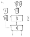
- FIG. 3 is a block diagram illustrating the construction of a digital broadcast receiver according to the first embodiment of the present invention.
- the digital broadcast receiver 102 successively switches a digital broadcasting channel at a predetermined time interval and outputs digital broadcastings of each channel.
- the digital broadcast receiver includes a Digital Multimedia Broadcasting (DMB) module 100 , a Transport Stream (TS) demultiplexer 110 , a timer 150 , a channel setup controller 160 , a codec 170 and an output unit, a speaker 180 and a display unit 190 .
- DMB Digital Multimedia Broadcasting
- TS Transport Stream
- the DMB module 100 receives predetermined digital broadcasting channels having been set by the channel setup controller 160 .
- the channel setup controller 160 sets the digital broadcasting channels determined by a predetermined broadcasting channel list to be received in the DMB module 100 .
- the channel setup controller 160 receives interrupt signals from the timer 150 at a predetermined time interval.
- the timer 150 provides the interrupt signals to the channel setup controller 160 at a predetermined time interval.
- the channel setup controller 160 sets different digital broadcasting channels other than the currently received digital broadcasting channels to be received in the DMB module 100 according to the predetermined channel list. That is, the channel setup controller 160 controls a switching of the digital broadcasting channels received in the DMB module 100 .
- the channel setup controller 160 controls the DMB module 100 to receive digital broadcastings while switching multiple digital broadcasting channels at the predetermined time interval.
- the predetermined broadcasting channel list may be automatically generated in the digital broadcast receiver according to a user's broadcasting channel preference. In the predetermined broadcasting channel list, an order of broadcasting channels may be determined according to the user's selection. Further, the channel setup controller 160 may use a broadcasting channel list acquired through the EPG channel.
- EPG Electronic Program Guide
- the channel setup controller 160 stops the setup operation to the DMB module 100 while switching digital broadcasting channels in response to a predetermined event generated in the digital broadcast receiver 102 .
- the predetermined event may be key input by a user, batterycharge level, etc. Further, the event may be a message or call reception or termination when the digital broadcast receiver is embodied in a mobile communication terminal. It should be understood that the scope of the present invention is not limited to these examples. That is, the predetermined event may be an event generated in the digital broadcast receiver 102 or any other single or combination of events generated in other apparatuses inter-working with the digital broadcast receiver 102 .
- the DMB module 100 opens a CDM channel corresponding to the digital broadcasting channel determined by the channel setup controller 160 , and receives broadcasting channel data.
- the DMB module 100 generates TS data based on the received broadcasting channel data and transfers the generated TS data to the TS demultiplexer 110 .
- the TS demultiplexer 110 demultiplexes the TS data and provides the demultiplexed data to the codec 170 .
- the codec 170 converts digital signals to voice signals and/or image signals, and outputs the voice signals and/or the image signals to the speaker 180 and the display unit 190 , respectively.
- the speaker 180 outputs the voice signals and the display unit 190 outputs the image signals.
- the digital broadcasting output from the digital broadcast receiver may be displayed in various ways.
- image signals may be displayed on the full screen of the display unit 190 in the digital broadcast receiver.
- the image signals may be partially displayed on any portion of the screen of the display unit 190 in the digital broadcast receiver according to a predetermined scheme such as a Picture-in-Picture (PIP) scheme. That is, in a state in which another moving picture or an image is displayed on the main screen of the display unit 190 , an automatically channel-switched digital broadcasting is displayed on the sub-screen of the display unit 190 . In this case, it is not preferred that the digital broadcast receiver does not output voice signals of the digital broadcasting channel to the speaker 180 .
- PIP Picture-in-Picture
- the digital broadcast receiver automatically switches and outputs digital broadcasting channels at a predetermined time interval, so that a user can successively watch various broadcasting programs without manipulating channel controls to change channels. Further, the digital broadcast receiver ends the automatic channel switching mode when key input or another event occurs during output of desired digital broadcasting.
- FIG. 4 is a flow chart illustrating a method for receiving the digital broadcasting in the automatic channel switching mode according to the first embodiment of the present invention.
- the digital broadcast receiver determines whether the automatic channel switching mode has been selected by a user. When it is determined that the automatic channel switching mode has been selected by the user, the digital broadcast receiver switches and outputs digital broadcastings at a predetermined time interval in step 320 .
- the predetermined time interval is determined by adding time required for a digital broadcasting channel switching to time required for recognition of the corresponding digital broadcasting channel by the user. For example, it is preferred that the predetermined time interval is about 10 seconds.
- the digital broadcasting channel switching requires about 3-4 seconds and the user can watch a digital broadcasting during 5-6 seconds (between channel switching), and recognize if the currently displayed broadcasting is a desired digital broadcasting for selection. Accordingly, the digital broadcast receiver can display stored still images and moving images during the time required for the digital broadcasting channel switching. Further, it is also possible to display previously stored advertisements or photographs.
- the automatically channel-switched digital broadcasting as described above may be displayed on the full screen of the display unit 190 or partially displayed on any portion of the screen of the display unit 190 according to a PIP scheme.
- the digital broadcast receiver determines if a predetermined event has occurred.
- the predetermined event may be key input by the user, a call reception, etc.
- the user can select a corresponding broadcasting by means of a predetermined key, etc., when a desired broadcasting is output from among circular broadcastings output at the predetermined time interval.
- the user can select a desired digital broadcasting channel simply by pressing any one of the keys installed in the digital broadcast receiver.
- a specific key may be designated for selection of a digital broadcasting channel from the keys installed in the digital broadcast receiver.
- the predetermined event denotes occurrence of an interrupt having a priority higher than digital broadcasting output in the digital broadcast receiver.
- the predetermined event may be a call termination, an SMS message termination, an alarm, a schedule, etc.
- the digital broadcast receiver continuously outputs the selected broadcasting in step 340 .
- the digital broadcast receiver controls the digital broadcasting channel displayed on the sub-screen to be continuously displayed on the main-screen.
- other digital broadcasting channels may be switched and displayed on the sub-screen as desired by the user, manufacturer, service provider, etc. Further, it may be impossible to display the sub-screen on the display unit 190 . This is an option that may be selected by a user or a manufacturer.
- step 320 is performed. That is, the digital broadcast receiver switches and outputs a digital broadcasting channel at a predetermined time interval.
- the digital broadcast receiver requires about 4-5 seconds for a channel switching. Therefore, the user must wait time after the broadcasting channel switching before another channel switching can be completed. According to another embodiment of the present invention, the digital broadcast receiver minimizes the time required for the channel switching in the automatic channel switching mode.
- FIG. 5 is a block diagram illustrating the construction of a digital broadcast receiver according to second embodiment of the present invention.
- the digital broadcast receiver includes a DMB module 100 , a TS demultiplexer 110 , a first channel buffer 120 , a second channel buffer 130 , a switch 140 , a timer 150 , a channel setup controller 160 , a codec 170 , and an output unit including a speaker 180 and a display unit 190 .
- the digital broadcast receiver successively switches a digital broadcasting channel at a predetermined time interval and outputs digital broadcastings of each channel. Accordingly, the DMB module 100 receives broadcasting channels to be currently output (e.g., the current channel) and the subsequent broadcasting channels to be output later. The DMB module 100 changes the received broadcasting channels at a predetermined time interval by the channel setup controller 160 .
- the channel setup controller 160 sets a Walsh code corresponding to CDM channels to be received.
- the DMB module 100 receives CDM channels based on two broadcasting channels determined by the channel setup controller 160 .
- the DMB module 100 generates and outputs TS data for the received broadcasting channels. Between the two broadcasting channels, one is buffered for a current user and is simultaneously output, and the other is buffered.
- the two broadcasting channels are determined by the channel setup controller 160 based on a predetermined broadcasting channel list, and provided to the DMB module 100 .
- the channel setup controller 160 controls the DMB module 100 to receive the two broadcasting channels determined based on the predetermined broadcasting channel list at a predetermined time interval. The passage of the predetermined time interval is notified to the channel setup controller 160 by the timer 150 . That is, the timer 150 outputs interrupt signals at a predetermined time intervals and provides the interrupt signals to the switch 140 and the channel setup controller 160 .
- the channel setup controller 160 controls the DMB module 100 to receive both a broadcasting channel, which is not being output, of the two broadcasting channels being currently received and other broadcasting channels not being currently received.
- the channel being currently received represents a broadcasting channel currently received in the DMB module 100 from among a plurality of DMB channels, and the channel not being currently received represents remaining broadcasting channels except for the broadcasting channel being currently received from among the DMB channels.
- the DMB module 100 receives two broadcasting, outputs one of the broadcasting channels through the speaker 180 or the display unit 190 , and does not output the other broadcasting channel. If the interrupt signals are received, the channel setup controller 160 controls the DMB module 100 to receive the broadcasting channel, which are not output through the speaker 180 or the display unit 190 from among the two broadcasting channels being currently received according to the present invention.
- the channel setup controller 160 controls a switching of the digital broadcasting channels received in the DMB module 100 .
- the channel setup controller 160 controls the DMB module 100 to receive digital broadcastings while switching the digital broadcasting channels at the predetermined time intervals according to channels to be currently output and channels to be output later.
- the DMB module 100 opens a CDM channel corresponding to the two digital broadcasting channels determined by the channel setup controller 160 , and receives broadcasting channel data.
- the DMB module 100 generates TS data as illustrated in FIG. 6 by means of the received broadcasting channel data.
- the DMB module 100 confirms stream types, channel numbers and PIDs of the two received broadcasting channels and then transfers the TS data for the two channels to the TS demultiplexer 110 .
- the TS 200 output from the DMB module 100 includes a mode field 210 , a stream type field 220 for one broadcasting channel, a channel number field 230 , a PID field 240 , an audio PMT PID field 250 , a stream type field 260 for another broadcasting channel, a channel number field 270 , a PID field 280 , and an audio PMT PID field 290 .
- the mode field 210 is used for identifying an automatic channel switching mode or a general channel switching mode. For example, 0x0 is a value for representing the general channel switching mode while 0x01 is a value for representing the automatic channel switching mode.
- the fields 220 , 230 , 240 , and 250 for said one broadcasting channel correspond to information for the current channel as described in FIG. 2 .
- the fields 260 , 270 , 280 , and 290 for said another broadcasting channel correspond to information for the next channel.
- the information for the next channel is valid only when a channel switching mode is the automatic channel switching mode.
- the DMB module 100 receives broadcasting channel data for the current channel and broadcasting channel data for the next channel, and transfers the TS data for the two channels to the TS demultiplexer 110 .
- the TS demultiplexer 110 demultiplexes the TS data according to each broadcasting channel, and provides the demultiplexed data to the first channel buffer 120 and the second channel buffer 130 .
- the first channel buffer 120 includes a first video buffer and a first audio buffer
- the second channel buffer 130 includes a second video buffer and a second audio buffer.
- Video channel data for said one broadcasting channel are stored in the first video buffer
- audio channel data for said one broadcasting channel are stored in the first audio buffer.
- video channel data for said another broadcasting channel are stored in the second video buffer
- audio channel data for said another broadcasting channel are stored in the second audio buffer.
- the broadcasting channel data stored in the channel buffers 120 and 130 are selectively output to the codec 170 by the switch 140 .
- the switch 140 switches the first channel buffer 120 and the second channel buffer 130 to the codec 170 at a predetermined time interval based on the timer 150 .
- the codec 170 converts digital signals from the first channel buffer 120 or the second channel buffer 130 through the switch 140 to voice signals or image signals, and outputs the voice signals and the image signals to the speaker 180 and the display unit 190 , respectively.
- the speaker 180 outputs the voice signals and the display unit 190 outputs the image signals.
- the digital broadcast receiver minimizes the time required for the broadcasting channel switching at a predetermined time interval in the automatic channel switching mode.
- FIG. 7 is a flow diagram illustrating a method for receiving the digital broadcasting in the automatic channel switching mode according to the second embodiment of the present invention.
- the digital broadcast receiver sets a Walsh code in order to receive two broadcasting channels based on a predetermined broadcasting channel list in step 410 .
- One of the two broadcasting channels is a broadcasting channel to be directly output to a user and the other is a broadcasting channel to be output after the directly output broadcasting channel is displayed.
- the digital broadcast receiver sets a Walsh code value for a CDM channel, which is to be received, in the DMB module 100 , and filters and receives only a TS packet having a PES PID within a maximum/minimum PID range of the set Walsh code. That is, the digital broadcast receiver sets Walsh codes for broadcasting channels, which are to be received, in the DMB module 100 .
- the digital broadcast receiver receives CDM channels according to the two broadcasting channels based on the set Walsh code.
- the digital broadcast receiver generates TS data including the two received broadcasting channel data.
- step 440 the digital broadcast receiver demultiplexes the TS data according to each broadcasting channel, buffers the demultiplexed TS data, and outputs video and audio data of said one buffered broadcasting channel.
- the digital broadcast receiver determines if a predetermined event has occurred.
- the occurrence of the predetermined event denotes occurrence of an interrupt having a priority higher than digital broadcasting output in the digital broadcast receiver.
- the predetermined event may be key input by the user. The user can select a desired digital broadcasting channel simply by pressing any one of the keys installed in the digital broadcast receiver.
- the digital broadcast receiver ends the automatic channel switching mode and continuously outputs the broadcasting channel being currently output. That is, the digital broadcast receiver stops the automatic channel switching and continuously outputs the broadcasting being currently displayed.
- the digital broadcast receiver outputs video and audio data of said another buffered broadcasting channel in step 470 .
- the predetermined time interval (which can be set by the user) to have a value so that a user can have sufficient time to watch a digital broadcasting, and can determine whether the digital broadcasting currently being displayed is desired for viewing. Accordingly, if the viewer desires to continue viewing the currently displayed channel, the user can select the channel for viewing using a key entry.
- step 410 is performed. That is, the digital broadcast receiver receives two broadcasting channels based on the predetermined broadcasting channel list.
- the digital broadcast receiver controls the DMB module to receive broadcasting channels to be currently output to the display unit or the speaker and the subsequent broadcasting channels to be output directly after the broadcasting channels.
- the digital broadcast receiver when the digital broadcast receiver has the predetermined broadcasting channel list as shown in Table 1 below, the digital broadcast receiver receives Channel 1 as digital broadcasting to be currently output and Channel 2 as the subsequent digital broadcasting to be output after Channel 1. Then, the digital broadcast receiver outputs the digital broadcasting data of Channel 1 and buffers the digital broadcasting data of Channel 2.
- the digital broadcast receiver stops receiving the digital broadcasting of Channel 1 and buffering the digital broadcasting of Channel 2, and receives the digital broadcasting of Channel 2 to be currently output and digital broadcasting of a Channel 3 to be output after Channel 2. Further, the digital broadcast receiver outputs the digital broadcasting of Channel 2 and buffers the digital broadcasting of Channel 3. In this way, the digital broadcast receiver successively outputs digital broadcasting channels in the broadcasting channel list at a predetermined time interval.
- the digital broadcast receiver switches and receives digital broadcasting channels in such a manner that it first receives Channel 1 and Channel 2, receives Channel 2 and Channel 3 after a predetermined time interval passes, and receives Channel 3 and Channel 4 after a predetermined time interval passes again.
- the digital broadcast receiver stops an automatic channel switching, and continuously receives and outputs the broadcasting being currently displayed.
- a user can successively view the broadcasting channels in the digital broadcasting channel list at a predetermined time interval in the digital broadcast receiver. Further, when the user desires to continuously watch the broadcasting being currently displayed, the user can select a corresponding broadcasting only by predetermined key input.
- a digital broadcast receiver successively and automatically switches multiple digital broadcasting channels at a predetermined time interval, outputs broadcasting of a corresponding channel, stops the automatic channel switching when key input is received from a user during the broadcasting, and continuously outputs broadcasting being currently displayed, thereby reducing inconvenience in that the user must view a plurality of programs being currently broadcasted one-by-one while manually and successively inputting a channel switching key in order to select a desired program from those being currently broadcasted, and minimizing the time required for channel switching.
Applications Claiming Priority (3)
| Application Number | Priority Date | Filing Date | Title |
|---|---|---|---|
| KR2005-61971 | 2005-07-09 | ||
| KR1020050061971A KR100557146B1 (ko) | 2005-07-09 | 2005-07-09 | 디지털 멀티미디어 방송 수신 장치 |
| KR10-2005-0061971 | 2005-07-09 |
Publications (2)
| Publication Number | Publication Date |
|---|---|
| US20070022454A1 US20070022454A1 (en) | 2007-01-25 |
| US8225349B2 true US8225349B2 (en) | 2012-07-17 |
Family
ID=36888862
Family Applications (1)
| Application Number | Title | Priority Date | Filing Date |
|---|---|---|---|
| US11/483,476 Expired - Fee Related US8225349B2 (en) | 2005-07-09 | 2006-07-10 | Apparatus for receiving digital multimedia broadcasting channels |
Country Status (6)
| Country | Link |
|---|---|
| US (1) | US8225349B2 (ko) |
| EP (1) | EP1748582A3 (ko) |
| JP (1) | JP4503562B2 (ko) |
| KR (1) | KR100557146B1 (ko) |
| CN (2) | CN101146187B (ko) |
| TW (1) | TWI338506B (ko) |
Cited By (1)
| Publication number | Priority date | Publication date | Assignee | Title |
|---|---|---|---|---|
| US20110157473A1 (en) * | 2009-12-30 | 2011-06-30 | Hoon Choi | Method, apparatus, and system for simultaneously previewing contents from multiple protected sources |
Families Citing this family (24)
| Publication number | Priority date | Publication date | Assignee | Title |
|---|---|---|---|---|
| US9008812B2 (en) | 2008-06-19 | 2015-04-14 | Sirius Xm Radio Inc. | Method and apparatus for using selected content tracks from two or more program channels to automatically generate a blended mix channel for playback to a user upon selection of a corresponding preset button on a user interface |
| KR100713515B1 (ko) * | 2005-01-25 | 2007-05-02 | 엘지전자 주식회사 | 디지털 방송 채널 전환 방법 |
| KR100716172B1 (ko) * | 2005-07-12 | 2007-05-10 | 삼성전자주식회사 | 디지털 방송 시스템의 채널 전환 장치 및 그 방법 |
| EP1879376A3 (en) | 2006-06-13 | 2011-04-06 | Samsung Electronics Co., Ltd. | Fast channel switching method and apparatus for digital broadcast receiver |
| KR101358709B1 (ko) * | 2006-06-13 | 2014-02-07 | 주식회사 더블유알지 | 디지털 방송수신기의 서비스채널 변경 장치 및 방법 |
| JP5230112B2 (ja) * | 2007-03-01 | 2013-07-10 | キヤノン株式会社 | 情報配信装置、情報配信方法及び情報配信プログラム |
| KR101366322B1 (ko) * | 2007-03-09 | 2014-02-21 | 엘지전자 주식회사 | 이동통신 단말기의 방송 채널 전환 방법 및 이동통신단말기 |
| TW200922185A (en) | 2007-09-26 | 2009-05-16 | Packetvideo Corp | System and method for receiving broadcast multimedia on a mobile device |
| KR100950057B1 (ko) * | 2007-10-31 | 2010-03-26 | (주)디코인 | 디엠비 채널 자동변경되는 이동형 영상기기 및 그의 디엠비채널 자동변경방법 |
| WO2009070343A1 (en) | 2007-11-27 | 2009-06-04 | Xm Satellite Radio Inc | Method for multiplexing audio program channels to provide a playlist |
| US20100094953A1 (en) * | 2008-10-09 | 2010-04-15 | Samsung Electronics Co., Ltd. | Method and apparatus for transmitting/receiving broadcast data through peer-to-peer network |
| CN101394499A (zh) * | 2008-10-29 | 2009-03-25 | 中兴通讯股份有限公司 | 一种在手机电视频道间进行自动转台的方法及手机终端 |
| KR101587095B1 (ko) * | 2008-12-02 | 2016-01-20 | 엘지전자 주식회사 | 영상표시장치 및 영상표시장치의 영상처리방법 |
| US8631436B2 (en) * | 2009-11-25 | 2014-01-14 | Nokia Corporation | Method and apparatus for presenting media segments |
| US8995327B2 (en) * | 2009-12-02 | 2015-03-31 | Mitsubishi Electric Research Laboratories, Inc. | Broadcasting messages in multi-channel vehicular networks |
| EP2676439B1 (en) * | 2011-02-14 | 2019-07-24 | Sirius Xm Radio Inc. | Method and apparatus for enhanced playback of content while switching among channels of broadcast or streamed content while being received |
| CN103905133A (zh) * | 2012-12-25 | 2014-07-02 | 联想(北京)有限公司 | 控制方法及电子设备 |
| US9430646B1 (en) | 2013-03-14 | 2016-08-30 | Fireeye, Inc. | Distributed systems and methods for automatically detecting unknown bots and botnets |
| CN104080001B (zh) * | 2014-06-23 | 2015-12-09 | 深圳市中兴移动通信有限公司 | 调频广播自动切换频道的方法和播放终端 |
| US20170199719A1 (en) * | 2016-01-08 | 2017-07-13 | KIDdesigns Inc. | Systems and methods for recording and playing audio |
| KR101681566B1 (ko) * | 2016-03-25 | 2016-12-02 | 리모트솔루션주식회사 | 다채널 시청이 가능한 텔레비젼 세트 |
| CN105957834A (zh) * | 2016-06-17 | 2016-09-21 | 京东方科技集团股份有限公司 | 薄膜晶体管阵列基板及其制备方法、显示装置 |
| CN111935523B (zh) * | 2020-08-17 | 2022-07-22 | 百度在线网络技术(北京)有限公司 | 频道控制方法、装置、设备及存储介质 |
| JP7468438B2 (ja) | 2021-03-31 | 2024-04-16 | 日本精工株式会社 | ボールねじ装置 |
Citations (27)
| Publication number | Priority date | Publication date | Assignee | Title |
|---|---|---|---|---|
| US5161019A (en) * | 1990-06-29 | 1992-11-03 | Rca Thomson Licensing Corporation | "channel guide" automatically activated by the absence of program information |
| KR940023202A (ko) | 1993-03-05 | 1994-10-22 | 신석균 | 가전기기의 채널자동 스캐닝시스템 |
| CN1154625A (zh) | 1995-09-18 | 1997-07-16 | 索尼公司 | 电视接收机和调谐控制方法 |
| WO1999016247A1 (en) | 1997-09-26 | 1999-04-01 | Sarnoff Corporation | Channel scanning and channel change latency reduction in an atsc television receiver |
| JP2001036835A (ja) | 1999-07-16 | 2001-02-09 | Toshiba Corp | 多チャンネル用テレビジョン受像機 |
| EP1185087A2 (en) | 2000-08-31 | 2002-03-06 | Matsushita Electric Industrial Co., Ltd. | Digital television channel surfing system |
| JP2002077458A (ja) | 2000-08-29 | 2002-03-15 | Hitachi Ltd | 携帯電話端末装置、携帯電話端末装置におけるコンテンツ再生中断再開方法、及びコンテンツ配信局 |
| JP2002335459A (ja) | 2001-05-09 | 2002-11-22 | Bangumi Joho Data Base Center Kk | 番組情報処理装置 |
| US20020175953A1 (en) * | 2001-04-20 | 2002-11-28 | Koninklijke Philips Electronics N.V. | Automatic selection of favorite media selections of a user of an media presentation device |
| US20030097659A1 (en) * | 2001-11-16 | 2003-05-22 | Goldman Phillip Y. | Interrupting the output of media content in response to an event |
| US20030115589A1 (en) * | 2001-12-17 | 2003-06-19 | D'souza Errol | System and method for automatically flagging a channel as a favorite channel |
| WO2004030352A1 (ja) | 2002-09-26 | 2004-04-08 | Sharp Kabushiki Kaisha | 適切なデータの候補を決定するデータ出力装置 |
| US6731345B2 (en) * | 2000-01-22 | 2004-05-04 | Lg Electronics Inc. | Method and apparatus for setting on-timer channel of digital broadcast receiver |
| US20040244048A1 (en) * | 2003-06-02 | 2004-12-02 | Kenji Wada | Receiving apparatus and receiving method |
| JP2005064566A (ja) | 2003-08-11 | 2005-03-10 | Fujitsu Ten Ltd | 受信装置および受信方法 |
| US20050114885A1 (en) * | 2003-11-21 | 2005-05-26 | Canon Kabushiki Kaisha | Program selecting method |
| WO2005060113A1 (ja) | 2003-12-16 | 2005-06-30 | Matsushita Electric Industrial Co., Ltd. | 受信装置及び受信方法 |
| US6956623B1 (en) * | 2001-08-27 | 2005-10-18 | At&T Corp. | Method and system for automatically scanning television channels |
| US20050273833A1 (en) * | 2004-05-14 | 2005-12-08 | Nokia Corporation | Customized virtual broadcast services |
| US20060271971A1 (en) * | 2003-06-13 | 2006-11-30 | Jonathan Peter Vincent Drazin | Interactive television system |
| US7227583B2 (en) * | 2002-12-11 | 2007-06-05 | Lg Electronics Inc. | Digital TV method for switching channel automatically |
| US7379122B2 (en) * | 2003-08-11 | 2008-05-27 | Lg Electronics, Inc. | Digital TV and channel setting method thereof |
| US7383567B2 (en) * | 2001-07-27 | 2008-06-03 | Thomson Licensing | Method and system for creating a subset of programming channels |
| US7668520B2 (en) * | 2005-06-21 | 2010-02-23 | Kyocera Corporation | Broadcast receiving apparatus and display control method |
| US7712123B2 (en) * | 2000-04-14 | 2010-05-04 | Nippon Telegraph And Telephone Corporation | Method, system, and apparatus for acquiring information concerning broadcast information |
| US7814421B2 (en) * | 1998-05-19 | 2010-10-12 | United Video Properties, Inc. | Program guide system with video window browsing |
| US20110173664A1 (en) * | 1998-08-21 | 2011-07-14 | United Video Properties, Inc. | Apparatus and method for constrained selection of favorite channels |
Family Cites Families (9)
| Publication number | Priority date | Publication date | Assignee | Title |
|---|---|---|---|---|
| US5233423A (en) * | 1990-11-26 | 1993-08-03 | North American Philips Corporation | Embedded commericals within a television receiver using an integrated electronic billboard |
| KR930003720A (ko) * | 1991-07-09 | 1993-02-24 | 강진구 | 자동 pip 채널 탐색 방법 |
| CN2183643Y (zh) * | 1993-05-04 | 1994-11-23 | 赵伟民 | 彩电节目循环装置 |
| IL111610A (en) * | 1994-11-11 | 1998-02-22 | News Datacom Ltd | Catv transmission systems |
| US5886746A (en) * | 1994-12-13 | 1999-03-23 | Gemstar Development Corporation | Method for channel scanning |
| US6115080A (en) * | 1998-06-05 | 2000-09-05 | Sarnoff Corporation | Channel selection methodology in an ATSC/NTSC television receiver |
| US20020083451A1 (en) * | 2000-12-21 | 2002-06-27 | Gill Komlika K. | User-friendly electronic program guide based on subscriber characterizations |
| US7065333B2 (en) * | 2001-05-11 | 2006-06-20 | Wildseed, Ltd. | Method and system for playing broadcasts with a mobile telecommunication device that includes multiple tuners |
| CN1256841C (zh) * | 2003-11-28 | 2006-05-17 | 深圳创维-Rgb电子有限公司 | 快速浏览节目的方法 |
-
2005
- 2005-07-09 KR KR1020050061971A patent/KR100557146B1/ko not_active IP Right Cessation
-
2006
- 2006-03-31 TW TW095111432A patent/TWI338506B/zh not_active IP Right Cessation
- 2006-07-07 JP JP2006188551A patent/JP4503562B2/ja not_active Expired - Fee Related
- 2006-07-10 US US11/483,476 patent/US8225349B2/en not_active Expired - Fee Related
- 2006-07-10 EP EP06014292A patent/EP1748582A3/en not_active Ceased
- 2006-07-10 CN CN2007101812035A patent/CN101146187B/zh not_active Expired - Fee Related
- 2006-07-10 CN CNB2006101017861A patent/CN100496102C/zh not_active Expired - Fee Related
Patent Citations (34)
| Publication number | Priority date | Publication date | Assignee | Title |
|---|---|---|---|---|
| US5161019A (en) * | 1990-06-29 | 1992-11-03 | Rca Thomson Licensing Corporation | "channel guide" automatically activated by the absence of program information |
| KR940023202A (ko) | 1993-03-05 | 1994-10-22 | 신석균 | 가전기기의 채널자동 스캐닝시스템 |
| CN1154625A (zh) | 1995-09-18 | 1997-07-16 | 索尼公司 | 电视接收机和调谐控制方法 |
| US5818541A (en) * | 1995-09-18 | 1998-10-06 | Sony Corporation | Television receiver and tuning control method including a program-scanning mode |
| CN1302506A (zh) | 1997-09-26 | 2001-07-04 | 萨尔诺夫公司 | Atsc电视接收机中频道扫描和频道转换的时延的减少 |
| WO1999016247A1 (en) | 1997-09-26 | 1999-04-01 | Sarnoff Corporation | Channel scanning and channel change latency reduction in an atsc television receiver |
| US6118498A (en) * | 1997-09-26 | 2000-09-12 | Sarnoff Corporation | Channel scanning and channel change latency reduction in an ATSC television receiver |
| US7814421B2 (en) * | 1998-05-19 | 2010-10-12 | United Video Properties, Inc. | Program guide system with video window browsing |
| US20110173664A1 (en) * | 1998-08-21 | 2011-07-14 | United Video Properties, Inc. | Apparatus and method for constrained selection of favorite channels |
| JP2001036835A (ja) | 1999-07-16 | 2001-02-09 | Toshiba Corp | 多チャンネル用テレビジョン受像機 |
| US6731345B2 (en) * | 2000-01-22 | 2004-05-04 | Lg Electronics Inc. | Method and apparatus for setting on-timer channel of digital broadcast receiver |
| US7712123B2 (en) * | 2000-04-14 | 2010-05-04 | Nippon Telegraph And Telephone Corporation | Method, system, and apparatus for acquiring information concerning broadcast information |
| JP2002077458A (ja) | 2000-08-29 | 2002-03-15 | Hitachi Ltd | 携帯電話端末装置、携帯電話端末装置におけるコンテンツ再生中断再開方法、及びコンテンツ配信局 |
| US6714264B1 (en) * | 2000-08-31 | 2004-03-30 | Matsushita Electric Industrial Co., Ltd. | Digital television channel surfing system |
| EP1185087A2 (en) | 2000-08-31 | 2002-03-06 | Matsushita Electric Industrial Co., Ltd. | Digital television channel surfing system |
| KR20020018604A (ko) | 2000-08-31 | 2002-03-08 | 모리시타 요이찌 | 디지털 텔레비전 채널 서핑 시스템 |
| JP2002125158A (ja) | 2000-08-31 | 2002-04-26 | Matsushita Electric Ind Co Ltd | デジタルテレビチャネルサーフィンシステム |
| US6934917B2 (en) * | 2001-04-20 | 2005-08-23 | Koninklijke Philips Electronics, N.V. | Automatic selection of favorite media selections of a user of a media presentation device |
| US20020175953A1 (en) * | 2001-04-20 | 2002-11-28 | Koninklijke Philips Electronics N.V. | Automatic selection of favorite media selections of a user of an media presentation device |
| JP2002335459A (ja) | 2001-05-09 | 2002-11-22 | Bangumi Joho Data Base Center Kk | 番組情報処理装置 |
| US7383567B2 (en) * | 2001-07-27 | 2008-06-03 | Thomson Licensing | Method and system for creating a subset of programming channels |
| US6956623B1 (en) * | 2001-08-27 | 2005-10-18 | At&T Corp. | Method and system for automatically scanning television channels |
| US20030097659A1 (en) * | 2001-11-16 | 2003-05-22 | Goldman Phillip Y. | Interrupting the output of media content in response to an event |
| US20030115589A1 (en) * | 2001-12-17 | 2003-06-19 | D'souza Errol | System and method for automatically flagging a channel as a favorite channel |
| WO2004030352A1 (ja) | 2002-09-26 | 2004-04-08 | Sharp Kabushiki Kaisha | 適切なデータの候補を決定するデータ出力装置 |
| US7227583B2 (en) * | 2002-12-11 | 2007-06-05 | Lg Electronics Inc. | Digital TV method for switching channel automatically |
| US20040244048A1 (en) * | 2003-06-02 | 2004-12-02 | Kenji Wada | Receiving apparatus and receiving method |
| US20060271971A1 (en) * | 2003-06-13 | 2006-11-30 | Jonathan Peter Vincent Drazin | Interactive television system |
| US7379122B2 (en) * | 2003-08-11 | 2008-05-27 | Lg Electronics, Inc. | Digital TV and channel setting method thereof |
| JP2005064566A (ja) | 2003-08-11 | 2005-03-10 | Fujitsu Ten Ltd | 受信装置および受信方法 |
| US20050114885A1 (en) * | 2003-11-21 | 2005-05-26 | Canon Kabushiki Kaisha | Program selecting method |
| WO2005060113A1 (ja) | 2003-12-16 | 2005-06-30 | Matsushita Electric Industrial Co., Ltd. | 受信装置及び受信方法 |
| US20050273833A1 (en) * | 2004-05-14 | 2005-12-08 | Nokia Corporation | Customized virtual broadcast services |
| US7668520B2 (en) * | 2005-06-21 | 2010-02-23 | Kyocera Corporation | Broadcast receiving apparatus and display control method |
Cited By (1)
| Publication number | Priority date | Publication date | Assignee | Title |
|---|---|---|---|---|
| US20110157473A1 (en) * | 2009-12-30 | 2011-06-30 | Hoon Choi | Method, apparatus, and system for simultaneously previewing contents from multiple protected sources |
Also Published As
| Publication number | Publication date |
|---|---|
| EP1748582A3 (en) | 2007-04-25 |
| JP4503562B2 (ja) | 2010-07-14 |
| TWI338506B (en) | 2011-03-01 |
| JP2007020190A (ja) | 2007-01-25 |
| CN100496102C (zh) | 2009-06-03 |
| CN1893579A (zh) | 2007-01-10 |
| EP1748582A2 (en) | 2007-01-31 |
| CN101146187B (zh) | 2010-09-29 |
| US20070022454A1 (en) | 2007-01-25 |
| TW200704172A (en) | 2007-01-16 |
| CN101146187A (zh) | 2008-03-19 |
| KR100557146B1 (ko) | 2006-03-03 |
| KR20050090954A (ko) | 2005-09-14 |
Similar Documents
| Publication | Publication Date | Title |
|---|---|---|
| US8225349B2 (en) | Apparatus for receiving digital multimedia broadcasting channels | |
| US8848112B2 (en) | Fast channel switching method and apparatus for digital broadcast receiver | |
| US8949924B2 (en) | Multi-screen display apparatus and method for digital broadcast receiver | |
| US20070288987A1 (en) | Device and method for editing channel list of digital broadcasting service | |
| KR100793736B1 (ko) | 다채널의 영상을 동시에 출력하는 디지털 방송 수신 장치 | |
| US7668520B2 (en) | Broadcast receiving apparatus and display control method | |
| KR20080025491A (ko) | 디지털 방송 수신기의 채널공유 방법 및 장치 | |
| CN101682710B (zh) | 广播接收装置和再现处理方法 | |
| US20070199024A1 (en) | Method for outputting digital broadcast in a digital broadcast reception device | |
| US20080074557A1 (en) | Method for switching a channel of an image display device and apparatus therefor | |
| KR100269370B1 (ko) | 디지털 위성 방송 수신기 및 타 채널 프로그램디스플레이 방법 | |
| KR20070079370A (ko) | 이동 방송 수신기 및 이동 방송 수신 데이터 처리방법 | |
| US7953364B2 (en) | Device for displaying digital broadcasting channel and method thereof | |
| KR101241893B1 (ko) | 디지털방송 수신기의 채널 재핑방법 및 장치 | |
| KR100767873B1 (ko) | 영상표시기기의 영상 선택장치 및 방법 | |
| US20100110296A1 (en) | Method of watching data broadcast and a receiving device for implementing the same | |
| JP2003319274A (ja) | デジタル放送受信機及び選局方法 | |
| KR20080005815A (ko) | 디지털 방송수신기의 다중화면 표시장치 및 방법 | |
| JP2006067599A (ja) | デジタルマルチメディア放送受信装置及び方法 | |
| JP4270833B2 (ja) | デジタル放送受信装置およびその受信方法 | |
| KR100867857B1 (ko) | 디지털 방송 시스템의 영상다중 방송 선택방법 | |
| KR20000028057A (ko) | 티 브이의 채널 전환장치 | |
| KR20070013708A (ko) | 방송 프로그램 예약 기능을 갖는 영상표시장치 및 그의동작 방법 | |
| KR20080045433A (ko) | 방송 수신 장치 및 방송 수신 방법 |
Legal Events
| Date | Code | Title | Description |
|---|---|---|---|
| AS | Assignment |
Owner name: SAMSUNG ELECTRONICS CO., LTD., KOREA, REPUBLIC OF Free format text: ASSIGNMENT OF ASSIGNORS INTEREST;ASSIGNORS:YOON, SANG-HYEON;CHANG, SUN-HEE;REEL/FRAME:018386/0653 Effective date: 20060918 |
|
| STCF | Information on status: patent grant |
Free format text: PATENTED CASE |
|
| FEPP | Fee payment procedure |
Free format text: PAYOR NUMBER ASSIGNED (ORIGINAL EVENT CODE: ASPN); ENTITY STATUS OF PATENT OWNER: LARGE ENTITY |
|
| FPAY | Fee payment |
Year of fee payment: 4 |
|
| FEPP | Fee payment procedure |
Free format text: MAINTENANCE FEE REMINDER MAILED (ORIGINAL EVENT CODE: REM.); ENTITY STATUS OF PATENT OWNER: LARGE ENTITY |
|
| LAPS | Lapse for failure to pay maintenance fees |
Free format text: PATENT EXPIRED FOR FAILURE TO PAY MAINTENANCE FEES (ORIGINAL EVENT CODE: EXP.); ENTITY STATUS OF PATENT OWNER: LARGE ENTITY |
|
| STCH | Information on status: patent discontinuation |
Free format text: PATENT EXPIRED DUE TO NONPAYMENT OF MAINTENANCE FEES UNDER 37 CFR 1.362 |
|
| FP | Lapsed due to failure to pay maintenance fee |
Effective date: 20200717 |