US8104617B2 - Overwrap packed body - Google Patents
Overwrap packed body Download PDFInfo
- Publication number
- US8104617B2 US8104617B2 US11/631,787 US63178705A US8104617B2 US 8104617 B2 US8104617 B2 US 8104617B2 US 63178705 A US63178705 A US 63178705A US 8104617 B2 US8104617 B2 US 8104617B2
- Authority
- US
- United States
- Prior art keywords
- perforated
- wrapping material
- lines
- perforated line
- packed
- Prior art date
- Legal status (The legal status is an assumption and is not a legal conclusion. Google has not performed a legal analysis and makes no representation as to the accuracy of the status listed.)
- Active, expires
Links
Images


Classifications
-
- B—PERFORMING OPERATIONS; TRANSPORTING
- B65—CONVEYING; PACKING; STORING; HANDLING THIN OR FILAMENTARY MATERIAL
- B65D—CONTAINERS FOR STORAGE OR TRANSPORT OF ARTICLES OR MATERIALS, e.g. BAGS, BARRELS, BOTTLES, BOXES, CANS, CARTONS, CRATES, DRUMS, JARS, TANKS, HOPPERS, FORWARDING CONTAINERS; ACCESSORIES, CLOSURES, OR FITTINGS THEREFOR; PACKAGING ELEMENTS; PACKAGES
- B65D71/00—Bundles of articles held together by packaging elements for convenience of storage or transport, e.g. portable segregating carrier for plural receptacles such as beer cans or pop bottles; Bales of material
- B65D71/06—Packaging elements holding or encircling completely or almost completely the bundle of articles, e.g. wrappers
- B65D71/08—Wrappers shrunk by heat or under tension, e.g. stretch films or films tensioned by compressed articles
-
- B—PERFORMING OPERATIONS; TRANSPORTING
- B65—CONVEYING; PACKING; STORING; HANDLING THIN OR FILAMENTARY MATERIAL
- B65B—MACHINES, APPARATUS OR DEVICES FOR, OR METHODS OF, PACKAGING ARTICLES OR MATERIALS; UNPACKING
- B65B61/00—Auxiliary devices, not otherwise provided for, for operating on sheets, blanks, webs, binding material, containers or packages
- B65B61/04—Auxiliary devices, not otherwise provided for, for operating on sheets, blanks, webs, binding material, containers or packages for severing webs, or for separating joined packages
- B65B61/12—Auxiliary devices, not otherwise provided for, for operating on sheets, blanks, webs, binding material, containers or packages for severing webs, or for separating joined packages by tearing along perforations or lines of weakness
-
- B—PERFORMING OPERATIONS; TRANSPORTING
- B65—CONVEYING; PACKING; STORING; HANDLING THIN OR FILAMENTARY MATERIAL
- B65D—CONTAINERS FOR STORAGE OR TRANSPORT OF ARTICLES OR MATERIALS, e.g. BAGS, BARRELS, BOTTLES, BOXES, CANS, CARTONS, CRATES, DRUMS, JARS, TANKS, HOPPERS, FORWARDING CONTAINERS; ACCESSORIES, CLOSURES, OR FITTINGS THEREFOR; PACKAGING ELEMENTS; PACKAGES
- B65D75/00—Packages comprising articles or materials partially or wholly enclosed in strips, sheets, blanks, tubes or webs of flexible sheet material, e.g. in folded wrappers
- B65D75/52—Details
- B65D75/58—Opening or contents-removing devices added or incorporated during package manufacture
- B65D75/5827—Tear-lines provided in a wall portion
- B65D75/5833—Tear-lines provided in a wall portion for tearing out a portion of the wall
- B65D75/5844—Tear-lines provided in a wall portion for tearing out a portion of the wall the portion of the wall being a narrow strip, e.g. between lines of weakness
-
- B—PERFORMING OPERATIONS; TRANSPORTING
- B65—CONVEYING; PACKING; STORING; HANDLING THIN OR FILAMENTARY MATERIAL
- B65D—CONTAINERS FOR STORAGE OR TRANSPORT OF ARTICLES OR MATERIALS, e.g. BAGS, BARRELS, BOTTLES, BOXES, CANS, CARTONS, CRATES, DRUMS, JARS, TANKS, HOPPERS, FORWARDING CONTAINERS; ACCESSORIES, CLOSURES, OR FITTINGS THEREFOR; PACKAGING ELEMENTS; PACKAGES
- B65D75/00—Packages comprising articles or materials partially or wholly enclosed in strips, sheets, blanks, tubes or webs of flexible sheet material, e.g. in folded wrappers
- B65D75/52—Details
- B65D75/58—Opening or contents-removing devices added or incorporated during package manufacture
- B65D75/5827—Tear-lines provided in a wall portion
- B65D75/585—Tear-lines provided in a wall portion the tear-lines being broken by deformation or bending
Definitions
- the present invention relates to an overwrap packed body in which a plurality of objects to be packed are wrapped with a wrapping material constituted by a shrink film and an overwrap packing is carried out thereto.
- the present invention relates to a perforated line forming method and apparatus for forming a plurality of perforated lines on the wrapping material in parallel, and more particularly to a perforated line forming method and a perforated line forming apparatus which are useful in the case in which an interval between perforated lines is small.
- a drink product DG obtained by filling a plastic vessel V having a small capacity with a drink.
- an overwrap packing is carried out by using a wrapping material PM constituted by a biaxially stretched film having a thermal shrinking property in order to integrally handle a plurality of drink products DG.
- a small hole p is formed on the wrapping material PM in each gap portion between the adjacent drink products DG. The wrapping material PM is broken when a small hole P portion is pushed with fingers, and the packed drink product DG can be thus taken out.
- the following method is employed, in related art of the present invention. That is, as shown in FIG. 15 , there are used a cutter roller CR having a large number of perforated line forming blades c provided at a predetermined interval over a whole periphery and a guide roller GR provided with a peripheral groove g for receiving the perforated line forming blade c of the cutter roller CR.
- the film F is fed on the guide roller GR, and the cutter roller CR is rotated in a state in which the perforated line forming blade c is inserted into the peripheral groove g formed on the guide roller GR.
- a perforated line is formed on the film F, by sequentially sticking the perforated line forming blade c to the film F.
- the plurality of perforated lines are formed at the same time by forming a plurality lines of perforated line forming blades c on the single cutter roller CR, in the related art.
- the interval between the perforated lines is small, it is difficult to individually form, on the guide roller GR, a plurality of peripheral grooves g respectively formed for receiving the plurality lines of perforated line forming blades c.
- a single peripheral groove g 1 for receiving the whole lines of perforated line forming blades c is formed on the guide roller GR.
- both side portions of each of the perforated line forming blades c in the film F are stretched toward the respective perforated line forming blade c sides, when the perforated line forming blade c sticks to the film F. Therefore, that the film F is broken at a cut portion constituting the perforated line formed on the film F by a tensile force and the film F is thus apt to be damaged.
- an overwrap packed body is provided with a plurality of objects to be packed, a wrapping material that wraps the plurality of objects to be packed, and a plurality of perforated lines formed in parallel and passing through a gap portion between the adjacent objects to be packed.
- each of the plurality of objects to be packed has a shoulder portion and has a vertically long and cylindrical shape
- the plurality of objects to be packed are arranged in line in a horizontal direction
- the plurality of perforated lines extend in line in the horizontal direction across shoulder portions of the plurality of objects to be packed.
- an interval between adjacent ones of the plurality of perforated lines is 1 to 3 mm.
- each of the plurality of perforated lines comprises a plurality of cuts arranged in line, and the plurality of cuts are formed at a pitch of 0.5 to 3.0 mm.
- phases of adjacent ones of the plurality of perforated lines are shifted from each other.
- a perforated line forming method for forming a plurality of perforated lines in parallel the method is provided with forming one part of the plurality of perforated lines on a film, and forming the other part of the plurality of perforated lines adjacent to the one part on the film formed with the one part.
- the plurality of perforated lines comprises three lines of the perforated lines, the one part comprises two outer lines, and the other part comprises one inner line.
- a perforated line forming method for forming a plurality of perforated lines in parallel, wherein each of the plurality of perforated lines comprises a plurality of cuts arranged in line
- the method is provided with forming a cut in one of the perforated lines and a cut in the other of the perforated lines at shifted timing.
- a perforated line forming apparatus for forming a plurality of perforated lines in parallel
- the apparatus is provided with a plurality of cutter rollers, each having a perforated line forming blade, and adjacent ones of the plurality of perforated lines are formed by respective perforated line forming blades on one of the plurality of cutter rollers and the other of the plurality of cutter rollers.
- the apparatus is further provided with a guide roller including a peripheral groove for receiving the perforated line forming blade.
- a perforated line forming apparatus for forming a plurality of perforated lines in parallel
- the apparatus is provided with a cutter roller including a plurality lines of perforated line forming blades, and adjacent ones of the plurality of perforated lines are formed by respective perforated line forming blades on one of the plurality lines and the other of plurality lines, wherein phases of the one and the other are shifted.
- the apparatus is further provided with a guide roller including a peripheral groove for receiving the perforated line forming blade.
- FIG. 1 is a perspective view showing an overwrap packed body according to one or more embodiments of the present invention in which a plurality of drink products is wrapped with a wrapping material.
- FIG. 2 is a perspective view showing a method of opening the overwrap packed body shown in FIG. 1 .
- FIG. 3 is a schematic view showing a perforated line forming apparatus for forming perforated lines on a wrapping material constituting the overwrap packed body shown in FIG. 1 .
- FIG. 4 is a plan view showing the perforated line forming apparatus shown in FIG. 3 .
- FIG. 5( a ) is a partial sectional view showing a cutter roller and a guide roller on an upstream side which constitute the perforated line forming apparatus shown in FIG. 3 .
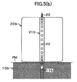
- FIG. 5( b ) is a partial sectional view showing a cutter roller and a guide roller on a downstream side which constitute the perforated line forming apparatus shown in FIG. 3 .
- FIG. 6( a ) is a plan view showing a variant embodiment of a perforated line forming blade.
- FIG. 6( b ) is a front view showing an edge of the perforated line forming blade shown in FIG. 6( a ).
- FIG. 6( c ) is a side view showing the perforated line forming blade shown in FIG. 6( a ).
- FIG. 7( a ) is a plan view showing a cutter line employing the variant embodiment of the perforated line forming blade shown in FIG. 6( a ).
- FIG. 7( b ) is a plan view showing a cutter line employing the variant embodiment of the perforated line forming blade shown in FIG. 6( a ).
- FIG. 8 is a schematic view showing a perforated line forming apparatus according to one or more embodiments of the present invention.
- FIG. 9 is a schematic view showing a perforated line forming apparatus according to one or more embodiments of the present invention.
- FIG. 10 is a plan view showing the perforated line forming apparatus shown in FIG. 9 .
- FIG. 11 is a plan view showing a cutter roller according to one or more embodiments of the present invention.
- FIG. 12 is a plan view showing a perforated line forming apparatus according to one or more embodiments of the present invention.
- FIG. 13 is a perspective view showing an example of a drink product.
- FIG. 14 is a perspective view showing a conventional overwrap packed body obtained by wrapping a plurality of drink products with a wrapping material.
- FIG. 15 is a view for explaining a perforated line forming method of forming a perforated line on a film according to related art of the present invention.
- FIG. 16 is a view for explaining the problems of the perforated line forming method according to the related art of the present invention.
- FIG. 1 Disclosed in FIG. 1 is an overwrap packed body OP in which a plurality of drink products DG are straightly arranged in a horizontal line and wrapped with a wrapping material PM.
- Each drink product DG is constituted by a plastic vessel with a top surface, a vertically long and cylindrical shape with an axis extending in a vertical direction. The vessel is filled with a drink.
- the wrapping material PM for example, a biaxially stretched polypropylene film having a thermal shrinking property in a thickness of 15 ⁇ m is used.
- five drink products DG are collectively wrapped, and the wrapping material PM is heated and shrank.
- three perforated lines MM passing through gap portions between the adjacent drink products DG and straightly extending across respective inclined shoulder portions SP of the drink products DG, are formed in parallel. Each interval between the adjacent perforated lines is 2 mm.
- the perforated line MM is formed as a starting point for tearing the wrapping material PM. Therefore, differently from a conventional overwrap packed body employing a small hole as the starting point for tearing the wrapping material, it is not necessary to consider the positional shift of the wrapping material PM in a direction in which the drink products DG are adjacent to each other when the five drink products DG are to be wrapped with the wrapping material PM. Consequently, it is possible to reliably form the starting point for tearing the wrapping material PM in the gap portions between the adjacent drink products DG.
- the three perforated lines MM are formed at an interval of 2 mm in parallel as the starting point for tearing the wrapping material PM, as compared with a conventional overwrap packed body in which only one small hole is formed as the staring point for tearing the wrapping material, tearing in a vertical direction can be easily occurred, so that the tearing property of the wrapping material PM can be more enhanced.
- the length of each cut (hole) should be set to be 0.1 to 0.8 mm and a pitch (a distance from one of the ends of the cut to one of the ends of an adjacent cut) should be set to be approximately 0.5 to 3.0 mm in the perforated line MM to be formed on the wrapping material PM.
- the three perforated lines MM are continuously formed on the long band-shaped wrapping material PM for wrapping the drink products DG by a perforated line forming apparatus 1 shown in FIGS. 3 and 4 .
- the perforated line forming apparatus 1 is incorporated as a part of a wrapping apparatus.
- FIG. 4 shows a state in which the wrapping material PM guided in a vertical direction on the upstream and downstream sides of the perforated line forming apparatus 1 is spread out in a transverse direction in order to easily understand the state in which the perforated line MM is formed on the wrapping material PM.
- the perforated line forming apparatus 1 is provided with guide rollers 10 a and 10 b formed of a metal and cutter rollers 20 a and 20 b arranged just above the guide rollers 10 a and 10 b .
- the long band-shaped wrapping material PM fed from a wrapping material roll is put on the guide rollers 10 a and 10 b .
- the wrapping material PM is interposed between the guide rollers 10 a and 10 b and the cutter rollers 20 a and 20 b .
- the cutter rollers 20 a and 20 b have cutter lines 21 a and 21 b , and a large number of perforated line forming blades 22 formed like a needle (conically) protrude from an outer peripheral surface at a predetermined interval over a whole periphery of the cutter rollers 20 a and 20 b.
- the cutter roller 20 a disposed on the upstream side in the direction of the feed of the wrapping material PM has a pair of cutter lines 21 a and 21 a for forming two outer perforated lines MM in the three perforated lines MM and provided at an interval of 4 mm in the transverse direction of the roller.
- peripheral grooves 11 a and 11 a are formed in order to respectively correspond to the respective cutter lines 21 a and 21 a .
- Each of the peripheral grooves 11 a and 11 a has a width of 1 mm and a depth of 2 mm, and receives respective one of the perforated line forming blades 22 .
- the cutter roller 20 b disposed on the downstream side in the direction of the feed of the wrapping material PM has the cutter line 21 b for forming one inner perforated line MM in the three perforated lines MM, and provided on a center in the transverse direction of the roller.
- a peripheral groove 11 b having a width of 1 mm and a depth of 2 mm for receiving the perforated line forming blade 22 constituting the cutter line 21 b is formed on the outer peripheral surface of the guide roller 10 b corresponding to the cutter roller 20 b in order to correspond to the cutter line 21 b.
- the long band-shaped wrapping material PM fed from the wrapping material roll passes through the guide roller 10 a , firstly.
- the perforated line forming blades 22 constituting a pair of cutter lines 21 a and 21 a in the cutter roller 20 a sequentially stick to the wrapping material PM in the peripheral groove 11 a and 11 a portions in the guide roller 10 a . Consequently, the two outer perforated lines MM in the three perforated lines MM are formed on the wrapping material PM.
- the wrapping material PM having the two perforated lines MM thus formed thereon subsequently passes through the guide roller 10 b .
- the perforated line forming blade 22 constituting the cutter line 21 b in the cutter roller 20 b sequentially sticks to the wrapping material PM in the peripheral groove 11 b portion in the guide roller 10 b . Consequently, the one inner perforated line MM in the three perforated lines MM is formed on the wrapping material PM. As a result, the three perforated lines are formed on the wrapping material PM.
- the two outer perforated lines MM are firstly formed on the wrapping material PM by the guide roller 10 a and the cutter roller 20 a which are provided on the upstream side and the one inner perforated line is then formed on the wrapping material PM by means of the guide roller 10 b and the cutter roller 20 b which are provided on the downstream side in such a manner that the adjacent perforated lines MM are not formed at the same time.
- the peripheral grooves 11 a and 11 a for receiving the perforated line forming blades 22 constituting the cutter lines 21 a and 21 a of the cutter roller 20 a respectively can be formed on the guide roller 10 a in an independent state for the respective cutter lines 21 a and 21 a.
- the perforated line forming apparatus 1 when the perforated line forming blades 22 constituting the cutter lines 21 a and 21 a of the cutter rollers 20 a respectively are to stick to the wrapping material PM, the amount of elongation and that of shift in the wrapping material PM can be minimized. Therefore, the amount of sticking of the perforated line forming blade 22 to the wrapping material PM can be prevented from being reduced. Thus, it is possible to reliably form a proper perforated line MM.
- the perforated line forming apparatus 1 since the perforated lines MM which are adjacent to each other are not formed at the same time, a tensile force applied to the cut portions constituting the two outer perforated lines MM formed at the same time is small. Therefore, it is difficult that the wrapping material PM is broken at the cut portions as a starting point. As a result, it is possible to form a fine perforated line MM without damaging the wrapping material PM.
- both side portions of the cut constituting the one perforated line MM formed earlier are stretched outward when the two outer perforated lines MM are to be formed. For this reason, the wrapping material PM is easily broken at the cut portion constituting the one perforated line MM formed earlier.
- the two outer perforated lines MM are firstly formed and the one inner perforated line MM is then formed. Therefore, when the one inner perforated line MM is to be formed, the either side portion of the cut constituting each of the two perforated lines MM formed earlier is simply stretched inward. Consequently, it is also possible to obtain an advantage that the wrapping material PM is broken with difficulty at the cut portions constituting the two perforated lines MM formed earlier respectively.
- the conical perforated line forming blade 22 having the diameter of a base end set to be 0.6 mm is employed in the embodiment, this is not restricted. It is preferable to properly set the shape and dimension of the perforated line forming blade in consideration of the function of a perforated line to be formed. It is desirable that at least a tip portion should be conical and the diameter of the base end should be set to be approximately 0.5 to 1.5 mm.
- the widths of the peripheral grooves 11 a and 11 b formed on the guide rollers 10 a and 10 b are set to be 1 mm in the embodiment, moreover, they are not restricted thereto but the width of the peripheral groove to be formed on the guide roller is preferably set properly corresponding to the diameter of the base end of the perforated line forming blade to be employed. In the case in which the perforated line forming blade having the diameter of the base end set to be approximately 0.5 to 1.5 mm is employed, for example, it is desirable that the width of the peripheral groove to be formed on the guide roller should be set to be approximately 0.7 to 2.0 mm.
- the conical perforated line forming blade 22 is used in the embodiment, this is not restricted.
- a perforated line forming blade 25 having a base end provided flatly by partially removing the base end of the conical perforated line forming blade as shown in FIG. 6( a ) to FIG. 6( c ).
- a cutter line 23 provided with a large number of perforated line forming blades 25 at a predetermined interval in such a manner that a cut surface 25 a of each perforated line forming blade 25 is turned in the circumferential direction of the cutter roller as shown in FIG.
- the perforated line forming method according to the invention can also be applied to the case in which two perforated lines or four perforated lines or more are to be formed.
- the perforated lines are formed one by one by a division into four stages or a first perforated line and a third perforated line are formed at the same time and a second perforated line and a fourth perforated line are then formed at the same time.
- a position in which the perforated line is to be formed is properly determined depending on the shape of an object to be packed, and it is preferable that the perforated lines should be formed to pass through a gap between the objects to be packed.
- the perforated lines should be formed to pass through a shoulder portion SP of the drink product DG.
- FIG. 8 Disclosed in FIG. 8 is a perforated line forming apparatus 2 according to a second embodiment of the present invention.
- the perforated line forming apparatus 2 two peripheral grooves 11 c and 11 c are formed on a single guide roller 10 c .
- Two cutter rollers 20 c and 20 d having cutter lines 21 c and 21 d are respectively arranged in different positions on the circumference of the guide roller 10 c .
- two adjacent perforated lines MM are formed stepwise in the same guide roller 10 c portion.
- FIG. 9 Disclosed in FIG. 9 is a perforated line forming apparatus 3 according to a third embodiment of the present invention.
- the perforated line forming apparatus 3 is provided with a single guide roller 10 d and a single cutter roller 20 e . On the cutter roller 20 e , two cutter lines 21 e 1 and 21 e 2 are provided.
- two peripheral grooves 11 d 1 and 11 d 2 are formed so as to respectively correspond to the two cutter lines 21 e 1 and 21 e 2 . Phases of the two cutter lines 21 e 1 and 21 e 2 are shifted to approximately 2 mm at positions where holes in the perforated lines are formed. As a result, as shown in FIG. 10 , the hole in the perforated line MM 1 formed by the cutter line 21 e 1 and the hole in the perforated line MM 2 formed by the cutter line 21 e 2 are shifted to approximately 2 mm. An interval between the cutter lines 21 e 1 and 21 e 2 is approximately 2.5 mm.
- an interval (a pitch) between cuts (holes having a diameter of 0.4 mm) in each perforated line MM 1 and MM 2 is 4 mm.
- the interval between the adjacent perforated lines MM 1 and MM 2 is approximately 2.5 mm, by arranging two cutter lines 21 e 1 and 21 e 2 within shifted phases on the single cutter roller 20 e , it is possible to form adjacent perforated lines MM 1 and MM 2 .
- Perforated line forming blades 22 and 22 are respectively provided on the cutter lines 21 e 1 and 21 e 2 .
- blades having needles, each needle having a sharp and conical leading edge with a diameter of approximately 1.2 mm may be used.
- a forming speed of the perforated lines may be set approximately 300 m for each 1 minute. (A feeding speed for forming the perforated lines may be 300 m/1 min.)
- FIG. 11 Disclosed in FIG. 11 is a cutter roller 20 f according to fourth embodiment.
- the cutter roller 20 f since an interval between adjacent cutter lines is narrow, and perforated line forming blades 22 L and 22 R of the adjacent cutter lines with shifted phases are formed in positions overlapping each other in a circumferential direction.
- the cutter roller 20 f is provided with a plurality of perforated line forming blades 22 R and a plurality of perforated line forming blades 22 L on an outer circumference thereof.
- a first cutter line and a second cutter line are formed so that phases are shifted.
- a common peripherall groove is formed for receiving the perforated line forming blades 22 R and 22 L of the both cutter lines.
- one line or two lines of cutter lines are formed on a single cutter roller, however, the present invention is not limited to them.
- three lines of cutter lines 21 g , 21 g and 21 g may be provided by shifting the phases between adjacent perforated line forming blades 22 , 22 and 22 .
- over four lines of cutter lines may be provided.
- the perforated line MM is formed on the wrapping material PM by using the cutter rollers 20 a and 20 b having the perforated line forming blades 22 and the guide rollers 10 a and 10 b having the peripheral grooves 11 a and 11 b for receiving the perforated line forming blades 22 , moreover, this is not restricted but it is also possible to use a receiving object taking the shape of a flat or curved plate which is provided with a groove for receiving the perforated line forming blade 22 in place of the guide rollers 10 a and 10 b.
- the perforated lines MM on the wrapping material PM can be formed in a slitter process for the wrapping material PM or a wrapping process using a pillow wrapping machine.
- the perforated lines passing through the gap portion between the adjacent objects to be packed are formed on the wrapping material in parallel.
- the wrapping material is broken in the perforated line portions when they are pushed with fingers.
- the perforated line is used as a staring point for tearing the wrapping material.
- the perforated line is used as a staring point for tearing the wrapping material.
- the perforated lines are formed in parallel at a small interval of 1 to 3 mm as a starting point for tearing the wrapping material.
- a breaking property can be more enhanced.
- the phases of the adjacent perforated lines are shifted from each other. Therefore, it is possible to form the adjacent perforated lines at the same time even if the interval between the adjacent perforated lines to be formed is small.
- the perforated lines are formed stepwise in such a manner that the adjacent perforated lines are not formed at the same time. Also in the case in which the interval between the perforated lines to be formed on the film is small, therefore, it is possible to form the peripheral groove for receiving the perforated line forming blade of the cutter roller on the guide roller in an independent state for each of the perforated line forming blades.
- the perforated line forming method is useful for a method of forming a plurality of perforated lines which wraps a plurality of objects to be wrapped by a wrapping material constituted by a biaxially stretched film having a thermal shrinking property to carry out overwrap packing and pushing, with fingers, a gap portion between the overwrap packed bodies thus obtained, thereby breaking and opening the wrapping material.
- the method is suitable for the case in which two to four perforated lines are formed in parallel at a small interval of approximately 1 to 3 mm over a thin wrapping material having a thickness of 10 to 30 ⁇ m.
Landscapes
- Engineering & Computer Science (AREA)
- Mechanical Engineering (AREA)
- Auxiliary Devices For And Details Of Packaging Control (AREA)
- Packages (AREA)
- Wrappers (AREA)
- Perforating, Stamping-Out Or Severing By Means Other Than Cutting (AREA)
Applications Claiming Priority (3)
| Application Number | Priority Date | Filing Date | Title |
|---|---|---|---|
| JP2004199103 | 2004-07-06 | ||
| JP2004-199103 | 2004-07-06 | ||
| PCT/JP2005/012349 WO2006004094A1 (ja) | 2004-07-06 | 2005-07-04 | オーバーラップ包装体、ミシン目形成方法、及び、ミシン目形成装置 |
Publications (2)
| Publication Number | Publication Date |
|---|---|
| US20080289986A1 US20080289986A1 (en) | 2008-11-27 |
| US8104617B2 true US8104617B2 (en) | 2012-01-31 |
Family
ID=35782895
Family Applications (1)
| Application Number | Title | Priority Date | Filing Date |
|---|---|---|---|
| US11/631,787 Active 2026-03-15 US8104617B2 (en) | 2004-07-06 | 2005-07-04 | Overwrap packed body |
Country Status (16)
| Country | Link |
|---|---|
| US (1) | US8104617B2 (de) |
| EP (1) | EP1764313B1 (de) |
| JP (2) | JP4722586B2 (de) |
| KR (1) | KR100921925B1 (de) |
| CN (1) | CN1997564B (de) |
| AR (1) | AR050677A1 (de) |
| AT (1) | ATE537076T1 (de) |
| AU (1) | AU2005258372B2 (de) |
| BR (1) | BRPI0512652B1 (de) |
| CA (1) | CA2571125C (de) |
| ES (1) | ES2375813T3 (de) |
| MX (1) | MXPA06014897A (de) |
| MY (1) | MY142201A (de) |
| NZ (1) | NZ552341A (de) |
| TW (1) | TWI323715B (de) |
| WO (1) | WO2006004094A1 (de) |
Cited By (3)
| Publication number | Priority date | Publication date | Assignee | Title |
|---|---|---|---|---|
| US10961005B1 (en) * | 2019-04-10 | 2021-03-30 | Moshe Epstein | Self-propelled, packaging film perforating system used in horizontal, form, fill, and seal packaging machines |
| US11565864B2 (en) | 2018-08-17 | 2023-01-31 | Niagara Bottling, Llc | Perforated case pack top panel |
| US12473132B2 (en) | 2023-03-09 | 2025-11-18 | Niagara Bottling, Llc | Perforated panel for bottle packaging |
Families Citing this family (13)
| Publication number | Priority date | Publication date | Assignee | Title |
|---|---|---|---|---|
| JP5036188B2 (ja) * | 2006-02-01 | 2012-09-26 | 株式会社フジシールインターナショナル | 熱収縮性筒状ラベル、及び熱収縮性フィルムの加工方法 |
| US8535464B2 (en) | 2007-04-05 | 2013-09-17 | Avery Dennison Corporation | Pressure sensitive shrink label |
| US8282754B2 (en) | 2007-04-05 | 2012-10-09 | Avery Dennison Corporation | Pressure sensitive shrink label |
| WO2009090930A1 (ja) | 2008-01-15 | 2009-07-23 | Hosokawa Yoko Co., Ltd. | 易開封包装袋 |
| US20120187010A1 (en) * | 2009-08-28 | 2012-07-26 | Treofan Germany Gmbh & Co.Kg | Polypropylene film comprising an opening aid |
| AU2010288875B2 (en) * | 2009-08-28 | 2014-07-17 | Treofan Germany Gmbh & Co. Kg | Polypropylene film comprising an opening aid |
| JP5692771B2 (ja) * | 2009-09-15 | 2015-04-01 | 花王株式会社 | フィルム孔あけ方法及びフィルム孔あけ装置 |
| EP2752366A1 (de) | 2010-01-28 | 2014-07-09 | Avery Dennison Corporation | Gurtsystem für Etikettenapplikator |
| US8814430B2 (en) | 2010-02-23 | 2014-08-26 | Kraft Foods R&D, Inc. | Food package having opening feature |
| FR2986516B1 (fr) * | 2012-02-06 | 2014-02-21 | Sidel Participations | Pack de recipients empilables groupes au moyen d'un film perce d'ouvertures |
| DE102012012407A1 (de) * | 2012-06-25 | 2014-01-02 | Khs Gmbh | Verfahren zur Herstellung einerVerpackungseinheit |
| FR3014729B1 (fr) | 2013-12-12 | 2016-08-26 | Francois Gosset | Procede de realisation d'une ligne de moindre resistance sur un film plastique |
| KR101455133B1 (ko) * | 2014-08-11 | 2014-10-27 | 애니텍비투비(주) | 핫팩용 봉지재 통기구멍 천공 장치 |
Citations (39)
| Publication number | Priority date | Publication date | Assignee | Title |
|---|---|---|---|---|
| US2285542A (en) * | 1939-07-15 | 1942-06-09 | Homer G Tasker | Wrapper |
| US3348671A (en) * | 1964-10-30 | 1967-10-24 | Mead Corp | Bottle carrier |
| US3542193A (en) * | 1968-10-09 | 1970-11-24 | American Home Prod | Package |
| US3587910A (en) * | 1969-04-25 | 1971-06-28 | Donal Edward Mccarthy | Disposable integral bottle and stacking cases |
| US3618757A (en) | 1970-01-29 | 1971-11-09 | Mead Corp | Article carrier |
| US3687282A (en) * | 1970-05-05 | 1972-08-29 | Illinois Tool Works | Container package |
| JPS4812281U (de) | 1971-06-22 | 1973-02-10 | ||
| US3746160A (en) * | 1971-01-21 | 1973-07-17 | Grace W R & Co | Hermetically sealed shipping package and method of preparing same |
| JPS57186362U (de) | 1981-05-22 | 1982-11-26 | ||
| JPS5836097U (ja) | 1981-08-31 | 1983-03-09 | 株式会社内田洋行 | ミシン目成形機 |
| US4382506A (en) * | 1980-03-12 | 1983-05-10 | The Mead Corporation | Multi unit package incorporating wrap-around handle |
| US4696402A (en) * | 1985-03-19 | 1987-09-29 | Rayovac Corporation | Easy-open, individual unit dispensing package |
| US4830895A (en) * | 1984-10-12 | 1989-05-16 | Minnesota Mining And Manufacturing Company | Heat shrink package handle |
| US4971197A (en) | 1989-12-06 | 1990-11-20 | Eveready Battery Company, Inc. | Battery package |
| JPH03111971U (de) | 1990-02-28 | 1991-11-15 | ||
| JPH0651487B2 (ja) | 1989-06-02 | 1994-07-06 | 旭化成ポリフレックス株式会社 | 易開封加工方法及びこれを用いた機械 |
| JPH074891B2 (ja) | 1990-01-31 | 1995-01-25 | 旭化成工業株式会社 | 易開封性密封袋の製造方法 |
| US5386752A (en) | 1992-11-04 | 1995-02-07 | Weldotron Of Delaware, Inc. | Perforation apparatus and method for use with sealing devices |
| JPH0829784B2 (ja) | 1991-11-21 | 1996-03-27 | 旭化成工業株式会社 | 密封袋用積層フィルム |
| JP2502860B2 (ja) | 1991-11-21 | 1996-05-29 | 旭化成工業株式会社 | 密封袋 |
| JP2525158B2 (ja) | 1986-09-22 | 1996-08-14 | 旭化成ポリフレツクス株式会社 | 易開封性袋の製造方法 |
| JP2731474B2 (ja) | 1991-11-21 | 1998-03-25 | 旭化成工業株式会社 | 密封袋およびその製造法 |
| JP2789524B2 (ja) | 1996-04-16 | 1998-08-20 | 株式会社東京パックス | 巻回テープの易引裂加工具及び加工方法 |
| JPH10287360A (ja) | 1997-04-10 | 1998-10-27 | Ajinomoto Co Inc | 易開封性包装用フィルム及びその製造法 |
| JPH1191821A (ja) | 1997-07-24 | 1999-04-06 | Soplaril Sa | プラスチックフィルムで包装された製品パックと、パック用プラスチック包装フィルムと、このプラスチックフィルムの製造方法 |
| WO1999052788A1 (en) | 1998-04-09 | 1999-10-21 | Asahi Breweries, Ltd. | Container with full-shrink label and tubular shrink label |
| US6050058A (en) * | 1995-12-12 | 2000-04-18 | Cielle Di Loreto Tommaso | Method for forming a packaging for a plurality of containers which is easily opened |
| US20020177513A1 (en) | 1999-03-12 | 2002-11-28 | Focke & Co. (Gmbh & Co.) | Package, especially for a group of cigarette packs, plus method and device for manufacturing same |
| JP2002362621A (ja) | 2001-06-05 | 2002-12-18 | Asahi Kasei Corp | 熱収縮フィルム包装体 |
| CN1388050A (zh) | 2001-05-25 | 2003-01-01 | 康思田 | 一种瓶装饮料包装盒 |
| JP2003095225A (ja) | 2001-09-21 | 2003-04-03 | Fuji Seal Inc | 耐破袋性及び切取り性に優れた切取り線付きチューブ状シュリンクラベル及び長尺チューブ |
| JP2003104335A (ja) | 2001-09-28 | 2003-04-09 | Sealed Air Japan Ltd | 包装体の製造方法 |
| JP2003104330A (ja) | 2001-09-28 | 2003-04-09 | Fuji Seal Inc | 耐破袋性に優れた切取り線付きシュリンクチューブ |
| JP2003300538A (ja) | 2002-02-07 | 2003-10-21 | Maruto Sangyo Kk | 包装用袋及び包装用袋に用いられる開封用誘導線の構造 |
| CN2589373Y (zh) | 2002-11-21 | 2003-12-03 | 海南现代企业股份有限公司 | 易撕开的包装膜 |
| EP1422158A1 (de) | 2002-11-21 | 2004-05-26 | Illinois Tool Works Inc. | Gebündelte Behälterverpackung |
| JP2004170634A (ja) | 2002-11-19 | 2004-06-17 | Fuji Seal Inc | 熱収縮性筒状フィルム |
| US6820745B1 (en) | 1999-11-02 | 2004-11-23 | Matsushita Electric Industrial Co., Ltd. | Package of cylindrical article and production method therefor |
| JP5432399B2 (ja) | 2012-06-22 | 2014-03-05 | シャープ株式会社 | 表示装置及びテレビジョン受信機 |
Family Cites Families (3)
| Publication number | Priority date | Publication date | Assignee | Title |
|---|---|---|---|---|
| JPS5432399B2 (de) * | 1971-09-10 | 1979-10-13 | ||
| JPS61115621U (de) * | 1984-12-29 | 1986-07-22 | ||
| JP2001354214A (ja) * | 2000-06-08 | 2001-12-25 | Kyoto Kasei Kogyo Kk | 切り離し本数設定機能付自動包装済マドラースプーン供給システム |
-
2005
- 2005-06-30 JP JP2005190884A patent/JP4722586B2/ja not_active Expired - Fee Related
- 2005-07-01 MY MYPI20053018A patent/MY142201A/en unknown
- 2005-07-01 TW TW094122261A patent/TWI323715B/zh not_active IP Right Cessation
- 2005-07-04 MX MXPA06014897A patent/MXPA06014897A/es active IP Right Grant
- 2005-07-04 NZ NZ552341A patent/NZ552341A/en not_active IP Right Cessation
- 2005-07-04 KR KR1020077000324A patent/KR100921925B1/ko not_active Expired - Lifetime
- 2005-07-04 CN CN2005800230661A patent/CN1997564B/zh not_active Expired - Lifetime
- 2005-07-04 CA CA2571125A patent/CA2571125C/en not_active Expired - Lifetime
- 2005-07-04 AR ARP050102767A patent/AR050677A1/es active IP Right Grant
- 2005-07-04 ES ES05765256T patent/ES2375813T3/es not_active Expired - Lifetime
- 2005-07-04 WO PCT/JP2005/012349 patent/WO2006004094A1/ja not_active Ceased
- 2005-07-04 AU AU2005258372A patent/AU2005258372B2/en not_active Expired
- 2005-07-04 US US11/631,787 patent/US8104617B2/en active Active
- 2005-07-04 AT AT05765256T patent/ATE537076T1/de active
- 2005-07-04 EP EP05765256A patent/EP1764313B1/de not_active Expired - Lifetime
- 2005-07-04 BR BRPI0512652-5A patent/BRPI0512652B1/pt active IP Right Grant
-
2011
- 2011-02-25 JP JP2011039194A patent/JP5277269B2/ja not_active Expired - Fee Related
Patent Citations (40)
| Publication number | Priority date | Publication date | Assignee | Title |
|---|---|---|---|---|
| US2285542A (en) * | 1939-07-15 | 1942-06-09 | Homer G Tasker | Wrapper |
| US3348671A (en) * | 1964-10-30 | 1967-10-24 | Mead Corp | Bottle carrier |
| US3542193A (en) * | 1968-10-09 | 1970-11-24 | American Home Prod | Package |
| US3587910A (en) * | 1969-04-25 | 1971-06-28 | Donal Edward Mccarthy | Disposable integral bottle and stacking cases |
| US3618757A (en) | 1970-01-29 | 1971-11-09 | Mead Corp | Article carrier |
| US3687282A (en) * | 1970-05-05 | 1972-08-29 | Illinois Tool Works | Container package |
| US3746160A (en) * | 1971-01-21 | 1973-07-17 | Grace W R & Co | Hermetically sealed shipping package and method of preparing same |
| JPS4812281U (de) | 1971-06-22 | 1973-02-10 | ||
| US4382506A (en) * | 1980-03-12 | 1983-05-10 | The Mead Corporation | Multi unit package incorporating wrap-around handle |
| JPS57186362U (de) | 1981-05-22 | 1982-11-26 | ||
| JPS5836097U (ja) | 1981-08-31 | 1983-03-09 | 株式会社内田洋行 | ミシン目成形機 |
| US4830895A (en) * | 1984-10-12 | 1989-05-16 | Minnesota Mining And Manufacturing Company | Heat shrink package handle |
| US4696402A (en) * | 1985-03-19 | 1987-09-29 | Rayovac Corporation | Easy-open, individual unit dispensing package |
| JP2525158B2 (ja) | 1986-09-22 | 1996-08-14 | 旭化成ポリフレツクス株式会社 | 易開封性袋の製造方法 |
| JPH0651487B2 (ja) | 1989-06-02 | 1994-07-06 | 旭化成ポリフレックス株式会社 | 易開封加工方法及びこれを用いた機械 |
| US4971197A (en) | 1989-12-06 | 1990-11-20 | Eveready Battery Company, Inc. | Battery package |
| JPH074891B2 (ja) | 1990-01-31 | 1995-01-25 | 旭化成工業株式会社 | 易開封性密封袋の製造方法 |
| JPH03111971U (de) | 1990-02-28 | 1991-11-15 | ||
| JPH0829784B2 (ja) | 1991-11-21 | 1996-03-27 | 旭化成工業株式会社 | 密封袋用積層フィルム |
| JP2502860B2 (ja) | 1991-11-21 | 1996-05-29 | 旭化成工業株式会社 | 密封袋 |
| JP2731474B2 (ja) | 1991-11-21 | 1998-03-25 | 旭化成工業株式会社 | 密封袋およびその製造法 |
| US5386752A (en) | 1992-11-04 | 1995-02-07 | Weldotron Of Delaware, Inc. | Perforation apparatus and method for use with sealing devices |
| US6050058A (en) * | 1995-12-12 | 2000-04-18 | Cielle Di Loreto Tommaso | Method for forming a packaging for a plurality of containers which is easily opened |
| JP2789524B2 (ja) | 1996-04-16 | 1998-08-20 | 株式会社東京パックス | 巻回テープの易引裂加工具及び加工方法 |
| JPH10287360A (ja) | 1997-04-10 | 1998-10-27 | Ajinomoto Co Inc | 易開封性包装用フィルム及びその製造法 |
| JPH1191821A (ja) | 1997-07-24 | 1999-04-06 | Soplaril Sa | プラスチックフィルムで包装された製品パックと、パック用プラスチック包装フィルムと、このプラスチックフィルムの製造方法 |
| US6105776A (en) | 1997-07-24 | 2000-08-22 | Soparil Sa | Pack of articles packaged using a plastic film and process for the manufacture of the plastic film |
| WO1999052788A1 (en) | 1998-04-09 | 1999-10-21 | Asahi Breweries, Ltd. | Container with full-shrink label and tubular shrink label |
| US20020177513A1 (en) | 1999-03-12 | 2002-11-28 | Focke & Co. (Gmbh & Co.) | Package, especially for a group of cigarette packs, plus method and device for manufacturing same |
| US6820745B1 (en) | 1999-11-02 | 2004-11-23 | Matsushita Electric Industrial Co., Ltd. | Package of cylindrical article and production method therefor |
| CN1388050A (zh) | 2001-05-25 | 2003-01-01 | 康思田 | 一种瓶装饮料包装盒 |
| JP2002362621A (ja) | 2001-06-05 | 2002-12-18 | Asahi Kasei Corp | 熱収縮フィルム包装体 |
| JP2003095225A (ja) | 2001-09-21 | 2003-04-03 | Fuji Seal Inc | 耐破袋性及び切取り性に優れた切取り線付きチューブ状シュリンクラベル及び長尺チューブ |
| JP2003104330A (ja) | 2001-09-28 | 2003-04-09 | Fuji Seal Inc | 耐破袋性に優れた切取り線付きシュリンクチューブ |
| JP2003104335A (ja) | 2001-09-28 | 2003-04-09 | Sealed Air Japan Ltd | 包装体の製造方法 |
| JP2003300538A (ja) | 2002-02-07 | 2003-10-21 | Maruto Sangyo Kk | 包装用袋及び包装用袋に用いられる開封用誘導線の構造 |
| JP2004170634A (ja) | 2002-11-19 | 2004-06-17 | Fuji Seal Inc | 熱収縮性筒状フィルム |
| CN2589373Y (zh) | 2002-11-21 | 2003-12-03 | 海南现代企业股份有限公司 | 易撕开的包装膜 |
| EP1422158A1 (de) | 2002-11-21 | 2004-05-26 | Illinois Tool Works Inc. | Gebündelte Behälterverpackung |
| JP5432399B2 (ja) | 2012-06-22 | 2014-03-05 | シャープ株式会社 | 表示装置及びテレビジョン受信機 |
Non-Patent Citations (5)
| Title |
|---|
| Chinese Office Action dated Feb. 27, 2009. |
| Extended European Search Report issued Nov. 18, 2010, in counterpart European Application No. 05765256.2. |
| Japanese Notice of Reason of Rejection, dated Feb. 3, 2010, issued in Application No. 2005-190884. |
| Japanese Office Action, dated Nov. 12, 2010, issued in Application No. 2005-190884. |
| New Zealand Office Action dated Apr. 21, 2009. |
Cited By (3)
| Publication number | Priority date | Publication date | Assignee | Title |
|---|---|---|---|---|
| US11565864B2 (en) | 2018-08-17 | 2023-01-31 | Niagara Bottling, Llc | Perforated case pack top panel |
| US10961005B1 (en) * | 2019-04-10 | 2021-03-30 | Moshe Epstein | Self-propelled, packaging film perforating system used in horizontal, form, fill, and seal packaging machines |
| US12473132B2 (en) | 2023-03-09 | 2025-11-18 | Niagara Bottling, Llc | Perforated panel for bottle packaging |
Also Published As
| Publication number | Publication date |
|---|---|
| ES2375813T3 (es) | 2012-03-06 |
| AU2005258372A1 (en) | 2006-01-12 |
| CN1997564B (zh) | 2012-01-18 |
| MXPA06014897A (es) | 2007-10-23 |
| JP5277269B2 (ja) | 2013-08-28 |
| CA2571125C (en) | 2010-09-07 |
| TW200615202A (en) | 2006-05-16 |
| NZ552341A (en) | 2010-08-27 |
| AU2005258372B2 (en) | 2011-06-23 |
| ATE537076T1 (de) | 2011-12-15 |
| KR100921925B1 (ko) | 2009-10-16 |
| JP4722586B2 (ja) | 2011-07-13 |
| EP1764313A4 (de) | 2010-12-22 |
| BRPI0512652A (pt) | 2008-03-25 |
| BRPI0512652B1 (pt) | 2017-11-14 |
| US20080289986A1 (en) | 2008-11-27 |
| KR20070047761A (ko) | 2007-05-07 |
| MY142201A (en) | 2010-10-29 |
| JP2011105391A (ja) | 2011-06-02 |
| EP1764313B1 (de) | 2011-12-14 |
| JP2006044797A (ja) | 2006-02-16 |
| WO2006004094A1 (ja) | 2006-01-12 |
| EP1764313A1 (de) | 2007-03-21 |
| TWI323715B (en) | 2010-04-21 |
| HK1106197A1 (en) | 2008-03-07 |
| CA2571125A1 (en) | 2006-01-12 |
| AR050677A1 (es) | 2006-11-15 |
| AU2005258372A2 (en) | 2006-01-12 |
| CN1997564A (zh) | 2007-07-11 |
Similar Documents
| Publication | Publication Date | Title |
|---|---|---|
| US8104617B2 (en) | Overwrap packed body | |
| JP5242930B2 (ja) | 上包み材の製造方法及び製造された上包み材を備えたパック | |
| CN100418711C (zh) | 用于对热收缩膜进行打孔或切割的装置 | |
| US6105776A (en) | Pack of articles packaged using a plastic film and process for the manufacture of the plastic film | |
| KR101028908B1 (ko) | 포장 방법 및 이에 의해 제조되는 팩 | |
| KR20070084242A (ko) | 용이한 개봉을 보장하는 필름 포장용지 | |
| JPH05124677A (ja) | 引裂き開放タブを有するキヤリヤストツク | |
| US7100762B2 (en) | Three pack container carrier | |
| JP5480061B2 (ja) | シュリンクフィルム包装体 | |
| JP4787030B2 (ja) | 熱収縮性筒状ラベル | |
| EP1785357B1 (de) | Vorrichtung und Verfahren zur Herstellung von leicht zu öffnenden Schrumpf-Verpackungen | |
| JP2016060535A (ja) | シュリンク包装体及びその包装装置 | |
| ITBO960058A1 (it) | Metodo per ottenere almeno una banda a strappo di apertura negli imballaggi del tipo termorestringenti utilizzanti spezzoni in foglio | |
| KR102408370B1 (ko) | 롤김밥용 포장체 및 그 제조방법 | |
| EP3793917B1 (de) | Flexibler behälterträger | |
| HK1106197B (en) | Overwrap package, perforation forming method, and perforation forming device | |
| WO2024187125A1 (en) | Perforated panel for bottle packaging | |
| JP5693830B2 (ja) | 手切れ性熱可塑性合成樹脂バンド | |
| JP2008155920A (ja) | シュリンク包装材 |
Legal Events
| Date | Code | Title | Description |
|---|---|---|---|
| AS | Assignment |
Owner name: KABUSHIKI KAISHA YAKULT HONSHA, JAPAN Free format text: ASSIGNMENT OF ASSIGNORS INTEREST;ASSIGNORS:GOTO, YOSHIHIRO;TERAMOTO, TADAYOSHI;TERADA, TAKAYUKI;REEL/FRAME:021256/0616 Effective date: 20080701 Owner name: TOHO SHOJI KABUSHIKI KAISHA, JAPAN Free format text: ASSIGNMENT OF ASSIGNORS INTEREST;ASSIGNORS:GOTO, YOSHIHIRO;TERAMOTO, TADAYOSHI;TERADA, TAKAYUKI;REEL/FRAME:021256/0616 Effective date: 20080701 |
|
| STCF | Information on status: patent grant |
Free format text: PATENTED CASE |
|
| FPAY | Fee payment |
Year of fee payment: 4 |
|
| MAFP | Maintenance fee payment |
Free format text: PAYMENT OF MAINTENANCE FEE, 8TH YEAR, LARGE ENTITY (ORIGINAL EVENT CODE: M1552); ENTITY STATUS OF PATENT OWNER: LARGE ENTITY Year of fee payment: 8 |
|
| MAFP | Maintenance fee payment |
Free format text: PAYMENT OF MAINTENANCE FEE, 12TH YEAR, LARGE ENTITY (ORIGINAL EVENT CODE: M1553); ENTITY STATUS OF PATENT OWNER: LARGE ENTITY Year of fee payment: 12 |