US8091797B2 - Trackway and method for manufacturing a trackway - Google Patents
Trackway and method for manufacturing a trackway Download PDFInfo
- Publication number
- US8091797B2 US8091797B2 US12/441,055 US44105507A US8091797B2 US 8091797 B2 US8091797 B2 US 8091797B2 US 44105507 A US44105507 A US 44105507A US 8091797 B2 US8091797 B2 US 8091797B2
- Authority
- US
- United States
- Prior art keywords
- concrete slabs
- trackway
- rail
- concrete
- slabs
- Prior art date
- Legal status (The legal status is an assumption and is not a legal conclusion. Google has not performed a legal analysis and makes no representation as to the accuracy of the status listed.)
- Expired - Fee Related, expires
Links
Images


Classifications
-
- E—FIXED CONSTRUCTIONS
- E01—CONSTRUCTION OF ROADS, RAILWAYS, OR BRIDGES
- E01B—PERMANENT WAY; PERMANENT-WAY TOOLS; MACHINES FOR MAKING RAILWAYS OF ALL KINDS
- E01B1/00—Ballastway; Other means for supporting the sleepers or the track; Drainage of the ballastway
- E01B1/002—Ballastless track, e.g. concrete slab trackway, or with asphalt layers
- E01B1/004—Ballastless track, e.g. concrete slab trackway, or with asphalt layers with prefabricated elements embedded in fresh concrete or asphalt
-
- E—FIXED CONSTRUCTIONS
- E01—CONSTRUCTION OF ROADS, RAILWAYS, OR BRIDGES
- E01B—PERMANENT WAY; PERMANENT-WAY TOOLS; MACHINES FOR MAKING RAILWAYS OF ALL KINDS
- E01B3/00—Transverse or longitudinal sleepers; Other means resting directly on the ballastway for supporting rails
- E01B3/28—Transverse or longitudinal sleepers; Other means resting directly on the ballastway for supporting rails made from concrete or from natural or artificial stone
- E01B3/40—Slabs; Blocks; Pot sleepers; Fastening tie-rods to them
-
- E—FIXED CONSTRUCTIONS
- E01—CONSTRUCTION OF ROADS, RAILWAYS, OR BRIDGES
- E01B—PERMANENT WAY; PERMANENT-WAY TOOLS; MACHINES FOR MAKING RAILWAYS OF ALL KINDS
- E01B5/00—Rails; Guard rails; Distance-keeping means for them
- E01B5/02—Rails
- E01B5/04—Grooved rails
-
- E—FIXED CONSTRUCTIONS
- E01—CONSTRUCTION OF ROADS, RAILWAYS, OR BRIDGES
- E01B—PERMANENT WAY; PERMANENT-WAY TOOLS; MACHINES FOR MAKING RAILWAYS OF ALL KINDS
- E01B5/00—Rails; Guard rails; Distance-keeping means for them
- E01B5/02—Rails
- E01B5/08—Composite rails; Compound rails with dismountable or non-dismountable parts
- E01B5/10—Composite grooved rails; Inserts for grooved rails
Definitions
- the present invention relates generally to a trackway for guiding rail-bound vehicles such as trains or trams, and particularly, to a trackway made of pre-fabricated concrete slabs and countersunk rails.
- the present invention also relates to a method for manufacturing the trackway.
- a trackway made of concrete slabs and rails is disclosed in which the various concrete slabs are shaped like base slabs and inner slabs.
- the base slabs and inner slabs are arranged in a displaced way from one another, which results in interlocking and connection of the abutting slabs.
- Each base slab and inner slab has a gap into which a rail, with elastomeric profiles, is jammed.
- Different types of rails can be used with such a configuration, differing especially in the shape of the rail foot. If a rail with a bulbous rail foot is used, the rail can be pressed into the corresponding elastomeric profile.
- DE 196 04 887 C2 discloses a ballast-free upper construction for rail trains in which rails with a bulbous rail foot are used. Grooves filled with an elastic profile element are located in the concrete slabs in the area in which the rails are installed. The rail, whose rail foot acts as a counter surface to the profile element, is inserted into the elastic profile element.
- the slabs consist of in-situ concrete and are made with a sliding molding method on the location.
- the individual slabs are connected to the subsurface and are arranged with gaps separating them from one another. Jamming bodies are placed in the gaps between the neighboring slabs to prevent the rails from stretching or moving longitudinally.
- the disadvantage of this design is that during manufacturing the individual slabs must reproduce exactly the course of the trackway line. In other words, the grooves manufactured for an initial slab must be truly aligned with the grooves of the next slab that is manufactured. Corrections are hardly possible without a great deal of effort. Moreover, because the slabs are independent from one another, when the sub-surface settles the course of the rails is greatly disturbed. Specifically, the sub-surface settling can cause the individual slabs to move out of the straight course of the rails which can loosen the fastening of the rails in the profile element. This could greatly endanger the operation of the train.
- the task of this invention is, therefore, to create a safe trackway for rail-guided vehicles that is quickly manufactured with simple and uniform structural components.
- Each rail is arranged in a countersunk way in at least one groove formed in the concrete slabs and guided by an elastic sleeve located within the groove.
- Each rail may include a rail head, a rail web, and a rail foot, wherein a minimum width of the groove is larger than the maximum width of the rail foot.
- the rail foot is preferably bulbous, and more preferably wedge-shaped, to facilitate assembly of the rail into an elastic sleeve located within the groove and also to prevent movement of the rail in an upward, vertical direction.
- the concrete slabs may be pre-fabricated parts that are manufactured uniformly.
- Each concrete slab may include positioning elements and connecting elements such that the concrete slabs may be firmly attached to one another.
- the positioning elements may be located at opposed ends of each concrete slab and the connecting elements may located on the sides of each concrete slab.
- the rails may be longer than a single concrete slab and may be pressed into the elastic sleeve of several concrete slabs due to the configuration of the rail foot and the groove.
- neighboring concrete slabs may be attached to one another in a defined way to create a continuous and uniform-acting trackway. As such, slight settlements of the sub-surface below a particular concrete slab will not lead to a height displacement of such concrete slab as compared to neighboring slabs. As a result, the rails remain safely guided in the groove and the elastic sleeve.
- the rails and concrete slabs constitute a continuous track that allows rail-guided trains or trams to travel on the track safely and without malfunctions.
- the simple and uniform concrete slabs constitute one continuous assembly and thus provide a stable trackway without numerous or differing structural parts that may, due to manufacturing or laying tolerances, create weak spots on the trackway.
- the rails may be welded continuously to one another, thus creating a long continuous trackway similar to a rigid track system for high-speed tracks.
- the trackway according to the present invention can also be profitably used for slower, rail-bound vehicles.
- the elastic sleeve can be made of a polyurethane or PU layer, which provides for easy manufacturing.
- the elastic sleeves can be made from a slab-shaped material and then incorporated into the pre-fabricated concrete slab.
- the concrete slab may be substantially shaped like the rail anchored in the concrete slab.
- Polyurethane is a suitable material for the elastic sleeve as it dampens noise and oscillations. Additionally, it is also very durable and can resist environmental factors acting upon it.
- the elastic sleeve may also have a substantially continuous profile such that laying the sleeve into several concrete slabs of the trackway can be done quickly and simply.
- each of the concrete slabs in the rigid track system may have individual sleeves arranged separately from the sleeves of the neighboring slab.
- the elastic sleeve may also be desirable for the elastic sleeve to consist primarily of a structural component that has a cross-section of constant thickness so that the sleeve can be manufactured easily and economically.
- the manufacturing can be done with a slab-shaped or extruded material. Even a cast shaped element has proven to be very advantageous for manufacturing the elastic sleeve.
- one of the rails can serve as a part of the casting.
- the elastic sleeve can, if cast or extruded, also have different thicknesses and need not have cross-section of constant thickness.
- the positioning elements of the concrete slabs may consist of at least one cam and at least one pocket located, for example, on the frontal sides of the concrete slabs that face neighboring, adjacent slabs.
- a cam of a first slab fits into a pocket of a neighboring second slab, thereby creating interlocking between the two slabs.
- the positioning elements can be configured such that the interlocking occurs as soon as the slabs are placed next to each other.
- the positioning elements may be configured such that the slabs are aligned with respect to one another on location. Regardless, the positioning elements allow for neighboring slabs to be sufficiently connected to each other to ensure a safe tightening of the rail.
- the connecting elements may include special screws that, once inserted, extend from the lateral front sides of a first slab to a second neighboring slab.
- the screws may be anchored in the neighboring slab by plastic anchoring bolts embedded into the slab. Additionally, the screws can be expansion screws in which a defined pre-tension can be applied to ensure that the neighboring slabs are tightly connected.
- the concrete slabs may be placed on a grit track formation. Placing the slabs on a grit track formation is particularly economical and yet is still a sufficient arrangement of the slabs, especially for vehicles traveling slowly.
- the sealing profile joint may be inserted between the neighboring concrete slabs before the slabs are screwed together and then can be tightly pressed into the gap between the two slabs by tightening the screw.
- an inner width of a groove of the elastic sleeve is the same or smaller than the width of the rail web, it can affect the clamping force of the rail. If the inner width is smaller than the width of the rail web, the elastic sleeve may be pressed together more forcefully, assuming the rail has been assembled, than if the inner width of the elastic sleeve is wider than the rail web width when the sleeve is in an unstressed state. As a result, when the inner width of a groove of the elastic sleeve is smaller than the rail web width, the rail's slipping resistance is increased.
- the concrete slab can be made from a material such as high-strength concrete and/or be executed with a surface structure, so that street vehicles can drive directly over it.
- a trackway may be rapidly and economically manufactured.
- the rail head of each rail may be wider than the rail foot of each rail so that the rail can support itself in the elastic sleeve above the rail head and be positioned with greater accuracy.
- the groove or grooves of a concrete slab may be formed in the slab. If the groove is arranged in the slab, itself, vehicles with rubber tires can drive over the slab. Alternatively, the grooves may be formed in a hump on the slab. The hump construction can allow for the use of additional sound insulation material and may also prevent dirt, rainwater, and snow drainage from penetrating into the groove. Additionally, for even better water drainage, it may be desirable that the humps be spaced apart so that there are gaps all the way to the concrete slab to allow rainwater that has collected between the rails to flow out towards the side of the slab.
- the present invention also encompasses a method for making a trackway for guiding rail-bound vehicles such as trains or trams.
- the trackway may be made of pre-fabricated concrete slabs with rails, as described above, with the rails in each slab being arranged in one groove and guided with an elastic sleeve.
- the slabs After the concrete slabs have been manufactured to include at least one groove, the slabs are built into the trackway, and then the rails are pressed into the elastic sleeve of several successive slabs. Additionally, since another rail assembly is not necessary, a very fast assembly of the trackway is possible. Moreover, after the rail is inserted into the elastic sleeve located in the groove, the rail is very accurately positioned and also stored in a cushioned way.
- the concrete slabs may be concreted with encased auxiliary rails that can be removed from the concrete slabs after the slabs have hardened.
- the auxiliary rails can be used to create the exact shape needed for the groove.
- the auxiliary rails may simply indicate the shape of the future groove so that the exact shape may be created by machining later. This may be desirable, for example, to address undercuts or slight drafts that may be caused by removal of the auxiliary rail from the concrete mold.
- the concrete slabs may be manufactured by concreting the slabs with the elastic sleeve as a built-in part together with the encased auxiliary rail.
- the elastic sleeve may then remain in the slab after the auxiliary rail has been removed from the slab. This can prevent one from having to assemble the sleeve separately. Accordingly, the concrete slab, in such an embodiment, may be ready for insertion of the rail immediately after manufacture.
- the encased auxiliary rail used to form the groove may be the same size or have the same dimensions as the size or dimensions of the elastic sleeve after a rail has been inserted therein.
- the elastic sleeve may then be built into the concrete slab after the slab has hardened and the auxiliary rail has been removed. This allows for a very fast assembly of the elastic sleeve and the rails into the concrete slab—especially when the sleeve used has a substantially continuous profile. With such a configuration, there are fewer bumps in the sleeve, which improves the sleeve's useful life. For example, after the concrete slabs have been laid to form the trackway, the elastic sleeve may then be inserted into the grooves of several slabs.
- each groove in a concrete slab may be made by grinding or milling in order to make the groove especially accurate to size.
- the basic shape of the groove may be formed with the auxiliary rail, albeit with larger dimensions, and then subsequent milling may create the exact form.
- the elastic sleeve may be made first and independently from the slab such that the sleeve, as a built-in-part, may be positioned in the slab's casing while the concrete is poured to form the slab.
- This can ensure, with factory-produced accuracy, that the sleeve, constituting the rail's mounting support, may be exactly positioned with respect to the track gauge or with respect to a curved shape of the track.
- it may be advantageous to concrete the slab with the head (i.e. the future upper side of the slab) facing downwards into the slab casing.
- the slab's casing may be removed and the concrete slabs may be built into the trackway, with the rails being pressed into the elastic sleeve of several slabs.
- the elastic sleeve As a built-in-part in the slab casing during the manufacturing process of the pre-fabricated slabs, but additional costs associated with assembling the elastic sleeve into a separately manufactured groove are also avoided. Additionally, this ensures that there will be no tolerances between the sleeve and the groove of the pre-fabricated concrete slab into which rainwater could penetrate and destroy the elastic sleeve or the concrete. Contrary to grouting a gap between the rail and the groove with an elastomer, the present invention also ensures that the elastomer will actually envelop the rail uniformly and no unwanted hollow spaces, caused by improper grouting, will be present.
- the recasting of the finished sleeve with the concrete of the pre-fabricated slab allows for durable, uniform and very precise positioning and setting of the rail.
- a fast assembly and, if necessary, a fast disassembly of the rail is ensured.
- the present invention makes it generally unnecessary to adjust the rail on location.
- a rail may be used for positioning the sleeve when concreting the pre-fabricated concrete slab. The rail may then be removed after the slab has been lifted from the casing. This simple method ensures that the elastic sleeve will retain the exact shape needed for subsequently installing a rail during assembly of the trackway. Given that a rail may be pressed into the elastic sleeve and also pulled out of it, the use of a rail piece for positioning of the sleeve during concreting can be very advantageous.
- the rails may be welded continuously to one another outside the slab and subsequently inserted into the sleeve. This creates an additional connection of each of the pre-fabricated concrete slabs to one another.
- the continuously welded rails create—apart from the positioning and connecting elements which may be used to attach the slabs—an extra way of attaching neighboring slabs to one another.
- train operation is safer by ensuring that the vehicle is maintained within the track.
- the continuously welded rails to be pressed into the sleeve. This can be done, for example, by driving a rail-laying vehicle over the rails which have been generally positioned over the groove. The weight of the rail-laying vehicle can gradually press the rail into the groove and in between the sleeve, thus achieving a continuous process that can be carried out very quickly for laying the continuously welded rails in the groove of a pre-fabricated slab.
- a grouting of the pre-fabricated slabs with the subsoil may be done by any way generally known to one of ordinary skill in the art.
- the slabs are positioned adjacent to each other on the track and are tightly attached to one another, a continuous trackway may be created that provides highly precise positioning and long-lasting attachment of the rails into the slabs. Accordingly, it may be desirable for the slabs to be attached with a screw connection to ensure that the slabs are pressed tightly against one another and to provide a firm trackway.
- an inner width of a groove of the elastic sleeve is manufactured to be the same or smaller than the width of the rail web, then the clamping force of the rails may be affected.
- FIG. 1 illustrates a top view of a pre-fabricated slab according to an embodiment of the present invention
- FIG. 2 illustrates a sectional view from a frontal area of a pre-fabricated slab according to an embodiment of the present invention
- FIG. 3 illustrates a longitudinal sectional view of the connecting point of two pre-fabricated concrete slabs according to an embodiment of the present invention
- FIG. 4 illustrates a connecting device between two pre-fabricated concrete slabs according to an embodiment of the present invention
- FIG. 5 illustrates a cross-sectional view through a laid pre-fabricated concrete slab according to an embodiment of the present invention
- FIGS. 6 and 7 illustrate a cross-sectional view through a laid pre-fabricated concrete slab with a hump according to an embodiment of the present invention.
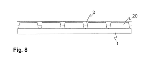
- FIG. 8 illustrates a lateral view of a pre-fabricated concrete slab with humps according to an embodiment of the present invention.
- FIG. 1 shows a top view of a pre-fabricated concrete slab 1 that is connected to neighboring pre-fabricated concrete slabs 1 ′ and 1 ′′.
- two rails 2 have been laid parallel to each other in the pre-fabricated concrete slab 1 .
- Each rail 2 may be laid continuously in an elastic sleeve 3 .
- Positioning elements may be located on the abutting faces or ends of the pre-fabricated concrete slabs 1 and 1 ′ or 1 and 1 ′′ and may include at least one cam 4 and at least one pocket 5 .
- the pre-fabricated concrete slab 1 includes positioning elements that have two cams 4 located on one end or face of the concrete slab 1 and two pockets 5 formed on the opposed end or face of the concrete slab 1 .
- each concrete slab may be configured to interlock
- the positioning elements allow the pre-fabricated concrete slabs 1 , 1 ′, and 1 ′′ to position themselves with respect to each other.
- connecting elements may be included to attach the pre-fabricated concrete slabs 1 , 1 ′, and 1 ′′ to one another.
- the connecting elements may comprise screws 6 that can be screwed from the lateral edge of the corresponding slab 1 , 1 ′ and 1 ′′ diagonally into the neighboring slab 1 , 1 ′, and 1 ′′.
- the two neighboring concrete slabs are pulled firmly towards one other, thereby creating a firm trackway that allows one to insert the rail 2 continuously into the elastic sleeve 3 .
- the concrete slabs 1 , 1 ′, and 1 ′′ may be firmly attached to one another so that the slabs become less sensitive to isolated settlements of the subsoil and are more suitable for withstanding higher loads.
- FIG. 2 shows a sectional view from an abutting face or end of the pre-fabricated concrete slab 1 such that it can be seen that the rail 2 has been sunk into a groove 15 formed in the pre-fabricated concrete slab 1 .
- the rail 2 is surrounded by the elastic sleeve 3 , which is tightly arranged directly in the groove 15 of the slab 1 .
- the rail 2 may consist of a rail head 7 , a rail web 8 , and a rail foot 9 . Since the rail web 8 may be thinner than the rail foot 9 , the rail foot 9 may have a bulbous shape to allow the rail 2 to be firmly placed or inserted within the elastic sleeve 3 .
- the width b of the rail foot 9 may also be smaller than the groove's width B in the slab 1 .
- the width B may have a measurement such that the rail foot 9 can be moved throughout when the rails 2 are pressed into or taken out through the area where the rail web 8 is located in the assembled state.
- the width B may also be dimensioned so that the width b of the rail foot 9 can be inserted into this area even with a constricted elastic sleeve 3 located in the groove 15 .
- the groove 15 may have dimensions so that more force than is expected is required to allow the rail 2 to be pressed into or pulled out of the groove 15 for assembly purposes.
- the rail head 7 may be wider than the rail foot 9 .
- FIG. 2 also illustrates a sectional view of the cam 4 .
- the cam 4 may have a conical shape so that neighboring concrete slabs can be easily inserted and centered with the concrete slab 1 .
- FIG. 3 illustrates a cross-sectional view of one embodiment of the positioning elements of the concrete slabs 1 and 1 ′.
- the positioning elements may include a cam 4 and a pocket 5 into which the cam 4 extends.
- the cam 4 and pocket 5 may have a conical shape so that the slabs 1 and 1 ′ can be centered when laid next to each other.
- a sealing joint 10 may be placed into a gap between the upper sides of the slabs 1 and 1 ′. When the slabs 1 and 1 ′ are mounted together and attached to one another, the sealing joint 10 is squeezed, thus sealing off the gap against rainwater.
- FIG. 4 illustrates an embodiment of a sectional view of two lateral surfaces of slabs 1 and 1 ′ with their corresponding connecting elements, which may include screws 6 that, starting from a first slab 1 , 1 ′, are screwed diagonally into the second slab 1 , 1 ′.
- An anchoring bolt 11 may be placed in the corresponding spot of the slab 1 , 1 ′ to allow the slabs to be screwed together.
- the screws 6 are expansion screws for applying pre-tension to press the slabs 1 , 1 ′ against one another with a defined force.
- FIG. 5 illustrates a sectional view of a frontal side or end of slab 1 that has been laid to form a track.
- the slab 1 has been laid on a grit track formation 12 arranged on a supporting layer 13 .
- the rail 2 is not fully sunk into the slab 1 , but is largely flush with a protective coating 14 .
- the protective coating 14 which can be a travel way covering for road traffic or for sealing off the slab 1 , may be applied to the top of the slab 1 .
- the elastic sleeve 3 may also be placed in the area of the protective coating 14 , between the protective coating 14 and the rail 2 . It should be appreciated that the protective coating 14 can be manufactured together with the pre-fabricated concrete slab 1 or be subsequently applied on the pre-fabricated concrete slab 1 .
- the slab 1 itself, may be made, in whole or in part, from a kind of concrete (e.g. high-strength concrete), which can allow road vehicles to be driven directly on the upper side of the slab 1 .
- a matrix may be embedded into the casing during the manufacturing of the slab 1 to reproduce the travel way structure in the upper side of the slab 1 .
- a brush stroke structure can be created on the upper side of the slab 1 or, if a protective coating 14 is used, on the protective coating 14 .
- the clamping force on the rail 2 can be affected.
- the elastic sleeve 3 may be pressed together with more strength when the rail 2 is in its built-in state than if the inner width n′, in its unstressed state, is equal to the width n of the rail web 8 .
- FIGS. 6 and 7 illustrate an embodiment of the present invention in which the rail 2 has been built into a hump 20 of the pre-fabricated concrete slab 1 .
- the rail 2 has been built all the way up into the rail head 7 in the elastic sleeve 3 .
- the elastic sleeve 3 does not envelop the rail head 7 .
- FIG. 8 illustrates a lateral view of a pre-fabricated concrete slab 1 with a plurality of humps 20 . Openings may be created between the humps and below the rail 2 or below the sleeve (not illustrated) through which accumulated rain or melt water can flow out from between parallel rails 2 of a track.
- the openings are gaps of the humps 20 that are preferably arranged in the slab 1 , in the area of indentations, which serve as break-off points of the slab 1 .
Landscapes
- Engineering & Computer Science (AREA)
- Architecture (AREA)
- Civil Engineering (AREA)
- Structural Engineering (AREA)
- Mechanical Engineering (AREA)
- Road Paving Structures (AREA)
- Machines For Laying And Maintaining Railways (AREA)
Applications Claiming Priority (4)
| Application Number | Priority Date | Filing Date | Title |
|---|---|---|---|
| DE102006043754.4 | 2006-09-13 | ||
| DE102006043745A DE102006043745A1 (de) | 2006-09-13 | 2006-09-13 | Fahrweg und Verfahren zur Herstellung eines Fahrweges |
| DE102006043745 | 2006-09-13 | ||
| PCT/EP2007/059591 WO2008031850A1 (de) | 2006-09-13 | 2007-09-12 | Fahrweg und verfahren zur herstellung eines fahrweges |
Publications (2)
| Publication Number | Publication Date |
|---|---|
| US20100001088A1 US20100001088A1 (en) | 2010-01-07 |
| US8091797B2 true US8091797B2 (en) | 2012-01-10 |
Family
ID=38739391
Family Applications (1)
| Application Number | Title | Priority Date | Filing Date |
|---|---|---|---|
| US12/441,055 Expired - Fee Related US8091797B2 (en) | 2006-09-13 | 2007-09-12 | Trackway and method for manufacturing a trackway |
Country Status (9)
| Country | Link |
|---|---|
| US (1) | US8091797B2 (pt) |
| EP (1) | EP2061933B1 (pt) |
| KR (1) | KR20090073118A (pt) |
| CN (1) | CN101522991A (pt) |
| BR (1) | BRPI0716898A2 (pt) |
| DE (1) | DE102006043745A1 (pt) |
| ES (1) | ES2426106T3 (pt) |
| RU (1) | RU2449071C2 (pt) |
| WO (1) | WO2008031850A1 (pt) |
Cited By (2)
| Publication number | Priority date | Publication date | Assignee | Title |
|---|---|---|---|---|
| US20110278366A1 (en) * | 2007-08-29 | 2011-11-17 | Lohr Industrie | Prefabricated module for the track of a self-guided urban transport vehicle on tyres |
| US8973318B2 (en) * | 2010-01-29 | 2015-03-10 | Precast Advanced Track Limited | Modular slab and modular surface system |
Families Citing this family (8)
| Publication number | Priority date | Publication date | Assignee | Title |
|---|---|---|---|---|
| DE102006043745A1 (de) * | 2006-09-13 | 2008-04-03 | Max Bögl Bauunternehmung GmbH & Co. KG | Fahrweg und Verfahren zur Herstellung eines Fahrweges |
| ES2363849B1 (es) * | 2009-06-16 | 2012-06-19 | Fcc Contrucción, S.A. | Procedimiento de instalación de vía en placa en túneles bitubo. |
| PT105840B (pt) * | 2011-07-28 | 2013-09-23 | Silvino Pompeu Santos | Ferrovia de estrutura melhorada |
| CN103769801B (zh) * | 2012-10-23 | 2017-02-01 | 南京梅山冶金发展有限公司 | 底侧卸式矿车卸载站空间曲轨制作方法 |
| RU2513329C1 (ru) * | 2013-02-04 | 2014-04-20 | Владимир Иосифович Петросян | Сборное рельсовое покрытие трамвайных и железнодорожных путей, способ крепления путевых рельсов (варианты) и путевая плита |
| WO2014201523A1 (en) * | 2013-06-21 | 2014-12-24 | Aurizon Operations Limited | Improvements in railway tracks |
| KR101678588B1 (ko) | 2014-11-21 | 2016-11-23 | 빌트원 주식회사 | 트램궤도 시공방법 |
| EA034498B1 (ru) | 2018-05-25 | 2020-02-13 | Анатолий Эдуардович Юницкий | Транспортная система юницкого, способ ее изготовления и монтажа |
Citations (13)
| Publication number | Priority date | Publication date | Assignee | Title |
|---|---|---|---|---|
| EP0672790A1 (de) | 1994-03-15 | 1995-09-20 | EUKA BAUELEMENTE VERKAUFSGESELLSCHAFT mbH | Längsschwellengleis |
| DE19604887A1 (de) | 1996-02-10 | 1997-08-14 | Metzer Horst | Schotterloser Oberbau für Schienenbahnen |
| US5806764A (en) * | 1994-12-30 | 1998-09-15 | Gmundner Fertigteile Gesellschaft M.B.H. & Co. Kg | Track |
| US20010052550A1 (en) * | 1997-07-04 | 2001-12-20 | Richard L. Byrne | Rail track having enhanced absorption of vibration and sound |
| WO2003016629A1 (de) * | 2001-08-14 | 2003-02-27 | Max Bögl Bauunternehmung GmbH & Co. KG | Verfahren zum kontinuierlichen lagern einer schiene auf einer festen fahrbahn sowie justiereinrichtung und feste fahrbahn |
| DE10209438A1 (de) | 2002-03-05 | 2003-09-18 | Ferd Braselmann Gmbh & Co Kg | Einrichtung zum Verbinden von Platten, insbesondere Betonplatten sowie feste Fahrbahn für Schienenfahrzeuge |
| US6752322B2 (en) * | 2002-01-24 | 2004-06-22 | Alstom | Method of constructing a rail track on a track-receiving concrete slab |
| US20040245353A1 (en) * | 2001-08-02 | 2004-12-09 | Charles Penny | Rail arrangement |
| DE202005020020U1 (de) | 2005-12-22 | 2006-02-23 | Edilon Gmbh | Querkraftkoppelung von Gleistragplatten |
| DE102004045766A1 (de) | 2004-09-21 | 2006-04-20 | Polyplan Gmbh Polyurethan-Maschinen | Fertigteilplatte zur lärmarmen Schienenlagerung |
| DE102004055727A1 (de) | 2004-11-18 | 2006-05-24 | Max Bögl Bauunternehmung GmbH & Co. KG | Verfahren zur Herstellung einer Plattenverbundkonstruktion aus Stahlbetonfertigteilplatten, Stahlbetonfertigplatte und Spanneinrichtung |
| US20070034705A1 (en) * | 2005-04-05 | 2007-02-15 | Metroshield, Llc | Insulated rail for electric transit systems and method of making same |
| US20100001088A1 (en) * | 2006-09-13 | 2010-01-07 | Max Bogl Bauunternehmung Gmbh & Co. Kg | Trackway and Method for Manufacturing a Trackway |
Family Cites Families (1)
| Publication number | Priority date | Publication date | Assignee | Title |
|---|---|---|---|---|
| RU2155838C1 (ru) * | 1999-05-26 | 2000-09-10 | Инжталант-ООО | Сборное железобетонное покрытие трамвайных путей и способ его сборки |
-
2006
- 2006-09-13 DE DE102006043745A patent/DE102006043745A1/de not_active Withdrawn
-
2007
- 2007-09-12 ES ES07803439T patent/ES2426106T3/es active Active
- 2007-09-12 BR BRPI0716898-5A patent/BRPI0716898A2/pt not_active IP Right Cessation
- 2007-09-12 CN CNA2007800339663A patent/CN101522991A/zh active Pending
- 2007-09-12 WO PCT/EP2007/059591 patent/WO2008031850A1/de active Application Filing
- 2007-09-12 KR KR1020097006180A patent/KR20090073118A/ko not_active Application Discontinuation
- 2007-09-12 US US12/441,055 patent/US8091797B2/en not_active Expired - Fee Related
- 2007-09-12 RU RU2009113601/11A patent/RU2449071C2/ru not_active IP Right Cessation
- 2007-09-12 EP EP07803439.4A patent/EP2061933B1/de not_active Not-in-force
Patent Citations (15)
| Publication number | Priority date | Publication date | Assignee | Title |
|---|---|---|---|---|
| EP0672790A1 (de) | 1994-03-15 | 1995-09-20 | EUKA BAUELEMENTE VERKAUFSGESELLSCHAFT mbH | Längsschwellengleis |
| US5806764A (en) * | 1994-12-30 | 1998-09-15 | Gmundner Fertigteile Gesellschaft M.B.H. & Co. Kg | Track |
| DE19604887A1 (de) | 1996-02-10 | 1997-08-14 | Metzer Horst | Schotterloser Oberbau für Schienenbahnen |
| US20010052550A1 (en) * | 1997-07-04 | 2001-12-20 | Richard L. Byrne | Rail track having enhanced absorption of vibration and sound |
| US20040245353A1 (en) * | 2001-08-02 | 2004-12-09 | Charles Penny | Rail arrangement |
| US20040182946A1 (en) * | 2001-08-14 | 2004-09-23 | Dieter Reichel | Method for the continuous laying of a rail on a rigid track in addition to an alignment device and a rigid track |
| WO2003016629A1 (de) * | 2001-08-14 | 2003-02-27 | Max Bögl Bauunternehmung GmbH & Co. KG | Verfahren zum kontinuierlichen lagern einer schiene auf einer festen fahrbahn sowie justiereinrichtung und feste fahrbahn |
| US6752322B2 (en) * | 2002-01-24 | 2004-06-22 | Alstom | Method of constructing a rail track on a track-receiving concrete slab |
| DE10209438A1 (de) | 2002-03-05 | 2003-09-18 | Ferd Braselmann Gmbh & Co Kg | Einrichtung zum Verbinden von Platten, insbesondere Betonplatten sowie feste Fahrbahn für Schienenfahrzeuge |
| DE102004045766A1 (de) | 2004-09-21 | 2006-04-20 | Polyplan Gmbh Polyurethan-Maschinen | Fertigteilplatte zur lärmarmen Schienenlagerung |
| DE102004055727A1 (de) | 2004-11-18 | 2006-05-24 | Max Bögl Bauunternehmung GmbH & Co. KG | Verfahren zur Herstellung einer Plattenverbundkonstruktion aus Stahlbetonfertigteilplatten, Stahlbetonfertigplatte und Spanneinrichtung |
| US20070034705A1 (en) * | 2005-04-05 | 2007-02-15 | Metroshield, Llc | Insulated rail for electric transit systems and method of making same |
| US7484669B2 (en) * | 2005-04-05 | 2009-02-03 | Metroshield Llc | Insulated rail for electric transit systems and method of making same |
| DE202005020020U1 (de) | 2005-12-22 | 2006-02-23 | Edilon Gmbh | Querkraftkoppelung von Gleistragplatten |
| US20100001088A1 (en) * | 2006-09-13 | 2010-01-07 | Max Bogl Bauunternehmung Gmbh & Co. Kg | Trackway and Method for Manufacturing a Trackway |
Non-Patent Citations (2)
| Title |
|---|
| German Search Report in German for 10 2006 043 745.4, Sep. 13, 2006. |
| Written Opinion and International Search Report, PCT/EP2007/059591, Dec. 18, 2007. |
Cited By (5)
| Publication number | Priority date | Publication date | Assignee | Title |
|---|---|---|---|---|
| US20110278366A1 (en) * | 2007-08-29 | 2011-11-17 | Lohr Industrie | Prefabricated module for the track of a self-guided urban transport vehicle on tyres |
| US8430333B2 (en) * | 2007-08-29 | 2013-04-30 | Lohr Industrie | Prefabricated module for the track of a self-guided urban transport vehicle on tyres |
| US8973318B2 (en) * | 2010-01-29 | 2015-03-10 | Precast Advanced Track Limited | Modular slab and modular surface system |
| US20150152638A1 (en) * | 2010-01-29 | 2015-06-04 | Precast Advanced Track Limited | Modular slab and modular surface system |
| US9574346B2 (en) * | 2010-01-29 | 2017-02-21 | Precast Advanced Track Limited | Modular slab and modular surface system |
Also Published As
| Publication number | Publication date |
|---|---|
| BRPI0716898A2 (pt) | 2013-10-22 |
| CN101522991A (zh) | 2009-09-02 |
| WO2008031850A1 (de) | 2008-03-20 |
| KR20090073118A (ko) | 2009-07-02 |
| EP2061933A1 (de) | 2009-05-27 |
| US20100001088A1 (en) | 2010-01-07 |
| DE102006043745A1 (de) | 2008-04-03 |
| RU2449071C2 (ru) | 2012-04-27 |
| RU2009113601A (ru) | 2010-10-20 |
| EP2061933B1 (de) | 2013-05-22 |
| ES2426106T3 (es) | 2013-10-21 |
Similar Documents
| Publication | Publication Date | Title |
|---|---|---|
| US8091797B2 (en) | Trackway and method for manufacturing a trackway | |
| US8671489B2 (en) | Device for bridging an expansion joint | |
| KR101293285B1 (ko) | 교량 구조물의 고정 주행 트랙 | |
| AU2005316083B2 (en) | Concrete track for rail vehicles | |
| JP2004538401A (ja) | 固定式軌道の上でレールを連続的に支承する方法、ならびに調節装置と固定式軌道 | |
| KR101780224B1 (ko) | 열차 운행을 고려하여 철도궤도를 개량하기 위한 급속경화궤도용 콘크리트 장침목 블록의 시공 방법 | |
| KR100603901B1 (ko) | 기존 거더의 일부를 활용한 판형교 유도상 구조 및 시공방법 | |
| RU2338025C1 (ru) | Ходовой рельс для рельсового корыта | |
| EP3067464B1 (fr) | Voie ferrée sur longrines longitudinales, procédé de réalisation | |
| DE4411833A1 (de) | Schallgedämpftes Straßenbahngleis | |
| CN111501428A (zh) | 一种直埋扣件及其施工方法 | |
| KR102212757B1 (ko) | 자갈궤도의 급속개량에 적합하게 사용될 수 있는 콘크리트궤도 시공방법 및 이를 위한 콘크리트슬래브 지지장치와 철도 부설장치 | |
| KR102249391B1 (ko) | 고무차륜 agt의 프리캐스트 콘크리트 주행로 블록 시공 방법 | |
| HU210631B (en) | Railway body | |
| EP0814197B1 (de) | Lagestabiles Gleis aus Betonfertigteilen | |
| US9644323B2 (en) | Train rail track structure systems | |
| CA2288731A1 (en) | Concrete surface | |
| KR102138365B1 (ko) | 종방향 슬립을 허용하는 강철도교용 무도상궤도 구조 | |
| DE102004037170A1 (de) | Schienenfahrweg | |
| DK2800833T3 (en) | fixed carriageway | |
| KR102696753B1 (ko) | 산악철도 랙 궤도용 콘크리트 패널 제작을 위한 직선부 몰드 구조체 및 이를 이용한 콘크리트 패널 제작방법 | |
| AT510523B1 (de) | Fahrbahn mit einer fahrbahnplatte | |
| KR20240043860A (ko) | 일반도로 병용 산악철도의 랙 궤도 구조 및 그 시공방법 | |
| EP3279397B1 (en) | Fixation of a rail to a tie plate by means of cylindrical clamping bolts | |
| CZ33669U1 (cs) | Přejezdová konstrukce |
Legal Events
| Date | Code | Title | Description |
|---|---|---|---|
| AS | Assignment |
Owner name: MAX BOGL BAUUNTERNEHMUNG GMBH & CO. KG, GERMANY Free format text: ASSIGNMENT OF ASSIGNORS INTEREST;ASSIGNORS:REICHEL, DIETER;BOGL, STEFAN;SIGNING DATES FROM 20090310 TO 20090312;REEL/FRAME:022386/0385 Owner name: MAX BOGL BAUUNTERNEHMUNG GMBH & CO. KG, GERMANY Free format text: ASSIGNMENT OF ASSIGNORS INTEREST;ASSIGNORS:REICHEL, DIETER;BOGL, STEFAN;REEL/FRAME:022386/0385;SIGNING DATES FROM 20090310 TO 20090312 |
|
| STCF | Information on status: patent grant |
Free format text: PATENTED CASE |
|
| FPAY | Fee payment |
Year of fee payment: 4 |
|
| FEPP | Fee payment procedure |
Free format text: MAINTENANCE FEE REMINDER MAILED (ORIGINAL EVENT CODE: REM.); ENTITY STATUS OF PATENT OWNER: LARGE ENTITY |
|
| LAPS | Lapse for failure to pay maintenance fees |
Free format text: PATENT EXPIRED FOR FAILURE TO PAY MAINTENANCE FEES (ORIGINAL EVENT CODE: EXP.); ENTITY STATUS OF PATENT OWNER: LARGE ENTITY |
|
| STCH | Information on status: patent discontinuation |
Free format text: PATENT EXPIRED DUE TO NONPAYMENT OF MAINTENANCE FEES UNDER 37 CFR 1.362 |
|
| FP | Lapsed due to failure to pay maintenance fee |
Effective date: 20200110 |