US7946947B2 - Automatic transmission - Google Patents
Automatic transmission Download PDFInfo
- Publication number
- US7946947B2 US7946947B2 US12/038,543 US3854308A US7946947B2 US 7946947 B2 US7946947 B2 US 7946947B2 US 3854308 A US3854308 A US 3854308A US 7946947 B2 US7946947 B2 US 7946947B2
- Authority
- US
- United States
- Prior art keywords
- gear
- carrier
- sun gear
- pinion
- ring gear
- Prior art date
- Legal status (The legal status is an assumption and is not a legal conclusion. Google has not performed a legal analysis and makes no representation as to the accuracy of the status listed.)
- Expired - Fee Related, expires
Links
Images


Classifications
-
- F—MECHANICAL ENGINEERING; LIGHTING; HEATING; WEAPONS; BLASTING
- F16—ENGINEERING ELEMENTS AND UNITS; GENERAL MEASURES FOR PRODUCING AND MAINTAINING EFFECTIVE FUNCTIONING OF MACHINES OR INSTALLATIONS; THERMAL INSULATION IN GENERAL
- F16H—GEARING
- F16H3/00—Toothed gearings for conveying rotary motion with variable gear ratio or for reversing rotary motion
- F16H3/44—Toothed gearings for conveying rotary motion with variable gear ratio or for reversing rotary motion using gears having orbital motion
- F16H3/62—Gearings having three or more central gears
- F16H3/66—Gearings having three or more central gears composed of a number of gear trains without drive passing from one train to another
-
- F—MECHANICAL ENGINEERING; LIGHTING; HEATING; WEAPONS; BLASTING
- F16—ENGINEERING ELEMENTS AND UNITS; GENERAL MEASURES FOR PRODUCING AND MAINTAINING EFFECTIVE FUNCTIONING OF MACHINES OR INSTALLATIONS; THERMAL INSULATION IN GENERAL
- F16H—GEARING
- F16H2200/00—Transmissions for multiple ratios
- F16H2200/003—Transmissions for multiple ratios characterised by the number of forward speeds
- F16H2200/006—Transmissions for multiple ratios characterised by the number of forward speeds the gear ratios comprising eight forward speeds
-
- F—MECHANICAL ENGINEERING; LIGHTING; HEATING; WEAPONS; BLASTING
- F16—ENGINEERING ELEMENTS AND UNITS; GENERAL MEASURES FOR PRODUCING AND MAINTAINING EFFECTIVE FUNCTIONING OF MACHINES OR INSTALLATIONS; THERMAL INSULATION IN GENERAL
- F16H—GEARING
- F16H2200/00—Transmissions for multiple ratios
- F16H2200/0082—Transmissions for multiple ratios characterised by the number of reverse speeds
- F16H2200/0086—Transmissions for multiple ratios characterised by the number of reverse speeds the gear ratios comprising two reverse speeds
-
- F—MECHANICAL ENGINEERING; LIGHTING; HEATING; WEAPONS; BLASTING
- F16—ENGINEERING ELEMENTS AND UNITS; GENERAL MEASURES FOR PRODUCING AND MAINTAINING EFFECTIVE FUNCTIONING OF MACHINES OR INSTALLATIONS; THERMAL INSULATION IN GENERAL
- F16H—GEARING
- F16H2200/00—Transmissions for multiple ratios
- F16H2200/20—Transmissions using gears with orbital motion
- F16H2200/2002—Transmissions using gears with orbital motion characterised by the number of sets of orbital gears
- F16H2200/2012—Transmissions using gears with orbital motion characterised by the number of sets of orbital gears with four sets of orbital gears
-
- F—MECHANICAL ENGINEERING; LIGHTING; HEATING; WEAPONS; BLASTING
- F16—ENGINEERING ELEMENTS AND UNITS; GENERAL MEASURES FOR PRODUCING AND MAINTAINING EFFECTIVE FUNCTIONING OF MACHINES OR INSTALLATIONS; THERMAL INSULATION IN GENERAL
- F16H—GEARING
- F16H2200/00—Transmissions for multiple ratios
- F16H2200/20—Transmissions using gears with orbital motion
- F16H2200/203—Transmissions using gears with orbital motion characterised by the engaging friction means not of the freewheel type, e.g. friction clutches or brakes
- F16H2200/2046—Transmissions using gears with orbital motion characterised by the engaging friction means not of the freewheel type, e.g. friction clutches or brakes with six engaging means
-
- F—MECHANICAL ENGINEERING; LIGHTING; HEATING; WEAPONS; BLASTING
- F16—ENGINEERING ELEMENTS AND UNITS; GENERAL MEASURES FOR PRODUCING AND MAINTAINING EFFECTIVE FUNCTIONING OF MACHINES OR INSTALLATIONS; THERMAL INSULATION IN GENERAL
- F16H—GEARING
- F16H2200/00—Transmissions for multiple ratios
- F16H2200/20—Transmissions using gears with orbital motion
- F16H2200/203—Transmissions using gears with orbital motion characterised by the engaging friction means not of the freewheel type, e.g. friction clutches or brakes
- F16H2200/2048—Transmissions using gears with orbital motion characterised by the engaging friction means not of the freewheel type, e.g. friction clutches or brakes with seven engaging means
-
- F—MECHANICAL ENGINEERING; LIGHTING; HEATING; WEAPONS; BLASTING
- F16—ENGINEERING ELEMENTS AND UNITS; GENERAL MEASURES FOR PRODUCING AND MAINTAINING EFFECTIVE FUNCTIONING OF MACHINES OR INSTALLATIONS; THERMAL INSULATION IN GENERAL
- F16H—GEARING
- F16H2200/00—Transmissions for multiple ratios
- F16H2200/20—Transmissions using gears with orbital motion
- F16H2200/203—Transmissions using gears with orbital motion characterised by the engaging friction means not of the freewheel type, e.g. friction clutches or brakes
- F16H2200/2051—Transmissions using gears with orbital motion characterised by the engaging friction means not of the freewheel type, e.g. friction clutches or brakes with eight engaging means
Definitions
- the present invention relates to an automatic transmission which transmits rotation of an input shaft to an output shaft while shifting in multiple stages by means of a planetary gear train.
- Patent document 1 discloses an automatic transmission which is equipped with a reduction double planetary gear train in which a common sun gear directly connected to an input shaft is in mesh with a first ring gear via a small-diameter pinion of a stepped pinion supported by a carrier and is in mesh with a second ring gear via a large-diameter pinion of the stepped pinion, a shifting double planetary gear train in which a sun gear of a first single pinion planetary gear train and a sun gear of a second single pinion planetary gear train are directly connected to each other and a carrier of the first single pinion planetary gear train and a ring gear of the second single pinion planetary gear train are directly connected to each other, a first clutch for selectively connecting the input shaft to the directly connected sun gears of the shifting double planetary gear train, a second clutch for selectively connecting the input shaft to
- the rate of increase of the gear ratio (the rotation speed of the input shaft divided by that of the output shaft) when the shift stage is raised by one stage is called “step ratio.”
- the step ratios be allocated to pairs of shift stages without large variations. If the step ratio itself of each pair of shift stages is too small (i.e., close to “1”), at the time of, for example, shifting with acceleration, a rotation speed drop in an effective rotation range of the engine is slight. Therefore, the driver is given only a slight degree of shift feeling and cannot have a sufficient feeling of acceleration at the time of the shifting.
- the step ratio between the fourth shift stage and the fifth shift stage and the step ratio between the fifth shift stage and the sixth shift stage are much different from the step ratios between the above shift stages and the adjacent, low-speed side and high-speed side shift stages.
- the step ratio between the sixth shift stage and the seventh shift stage which are as high-speed stages has a small value of less than 1.1 which can hardly provide a shift feeling. Therefore, an automatic transmission having gear ratios of forward eight stages with properly allocated step ratios is desired which can provide a sufficient feeling of acceleration with a clear shift feeling at the time of shifting with acceleration and is thus better than the above conventional automatic transmission.
- the present invention has been made in view of the above circumstances, and an object of the invention is therefore to provide an automatic transmission capable of providing a sufficient feeling of acceleration with a clear shift feeling at the time of shifting with acceleration by properly allocating step ratios between shift stages.
- the invention recited in a first aspect which relates to an automatic transmission is characterized by comprising a reduction double planetary gear train having a first planetary gear mechanism and a second planetary gear mechanism both being of a single pinion type and a shifting double planetary gear train having a third planetary gear mechanism and a fourth planetary gear mechanism both being of a single pinion type.
- the first planetary gear mechanism comprises a first sun gear, a first carrier which supports a first pinion being in mesh with the first sun gear, and a first ring gear being in mesh with the first pinion
- the second planetary gear mechanism comprises a second sun gear, a second carrier which supports a second pinion being in mesh with the second sun gear and is linked to the first ring gear, and a second ring gear which is in mesh with the second pinion and is linked to the first carrier
- the second sun gear is linked to an input shaft in a power-transmissible manner
- the first sun gear is linked to a third control brake
- the second ring gear and the first carrier are linked to each other and linked to a first control brake
- the third planetary gear mechanism comprises a third sun gear, a third carrier which supports a third pinion being in mesh with the third gear, and a third ring gear which is in mesh with the third pinion and is linked to the second carrier in
- step ratios each of which is a rate of increase of the gear ratio (the rotation speed of the input shaft divided by that of the output shaft) when the shift stage is raised by one stage, are allocated without large variations from one pair of shift stages to another.
- the step ratio values of the respective pairs of shift stages even the minimum step ratio value is sufficiently separated from “1,” that is, larger than “1.1” which is expected to provide a shift feeling. Therefore, since the step ratios between the shift stages are allocated properly, a sufficient feeling of acceleration can be obtained with a clear shift feeling at the time of shifting with acceleration.
- the invention recited in claim 2 is characterized in that, in the automatic transmission recited in claim 1 , a third control clutch for preventing fast rotation of the first sun gear is further provided.
- the invention recited in a second aspect can provide the same workings/advantage as the invention recited in the first aspect.
- the invention recited in the second aspect can prevent a phenomenon that the first sun gear rotates very fast in the reverse direction by disengaging the third control clutch at the time of prescribed shifting.
- the invention recited in a third aspect is characterized in that, in the automatic transmission recited in the second aspect, the third control clutch selectively links the input shaft to the second sun gear.
- the invention recited in the third aspect can provide the same workings/advantages as the invention recited in the second aspect.
- the invention recited in claim 4 is characterized in that, in the automatic transmission recited in the second aspect, the third control clutch selectively links the first ring gear and the second carrier to the third ring gear.
- the invention recited in a fourth aspect can provide the same workings/advantages as the invention recited in the second aspect.
- FIG. 1 is a skeleton view of an automatic transmission according to a first embodiment.
- FIG. 2 is a table showing how control clutches and control brakes are activated at each shift stage in the first embodiment.
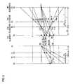
- FIG. 3 is a speed diagram showing gear ratios of respective elements of planetary gear trains at each shift stage in the first embodiment.
- FIG. 4 is a skeleton view of an automatic transmission according to a second embodiment.
- FIG. 5 is a speed diagram showing gear ratios of respective elements of planetary gear trains at each shift stage in the second embodiment.
- FIG. 6 is a skeleton view of an automatic transmission according to a third embodiment.
- FIG. 7 is a table showing how control clutches and control brakes are activated at each shift stage in the third embodiment.
- FIG. 8 is a speed diagram showing gear ratios of respective elements of planetary gear trains at each shift stage in the third embodiment.
- FIG. 9 is a skeleton diagram of an automatic transmission according to another embodiment.
- FIG. 10 is a skeleton diagram of an automatic transmission according to another embodiment.
- FIG. 11 is a skeleton diagram of an automatic transmission according to another embodiment.
- FIG. 12 is a skeleton diagram of an automatic transmission according to still another embodiment.
- FIG. 13 is a skeleton diagram of an automatic transmission according to another embodiment.
- FIG. 14 is a skeleton diagram of an automatic transmission according to another embodiment.
- FIG. 15 is a skeleton diagram of an automatic transmission according to yet another embodiment.
- FIG. 16 is a skeleton diagram of an automatic transmission according to another embodiment.
- FIG. 17 is a skeleton diagram of an automatic transmission according to a further embodiment.
- FIG. 1 is a skeleton view of an automatic transmission 10 according to the embodiment.
- This automatic transmission 10 is used for transmitting, to a drive wheel, output rotation of a fluid torque converter 11 which is rotation-driven by an automobile engine, for example, while changing speed.
- the automatic transmission 10 is equipped with a transmission case 12 to be attached to a vehicle body, and an input shaft 14 , a reduction double planetary gear train 15 , a shifting double planetary gear train 16 , and an output shaft 17 which are arranged in this order front to rear (in FIG. 1 , left to right) and supported on a common axis 13 which passes through the transmission case 12 approximately down the middle.
- a single pinion first planetary gear mechanism 21 and a single pinion second planetary gear mechanism 22 are disposed as a front stage and a rear stage, respectively.
- a single pinion third planetary gear mechanism 23 and a single pinion fourth planetary gear mechanism 24 are disposed as a front stage and a rear stage, respectively.
- the front, first planetary gear mechanism 21 is equipped with a first sun gear S 0 which is rotatably supported on the common axis 13 , a first carrier C 0 which rotatably supports a first pinion 25 being in mesh with the first sun gear S 0 and is rotatably supported on the common axis 13 , and a first ring gear R 0 which is in mesh with the first pinion 25 and is rotatably supported on the common axis 13 .
- the rear, second planetary gear mechanism 22 is equipped with a second sun gear S 1 which is rotatably supported on the common axis 13 , a second carrier C 1 which rotatably supports a second pinion 27 being in mesh with the second sun gear S 1 , is linked to the first ring gear R 0 , and is rotatably supported on the common axis 13 , and a second ring gear R 1 which is in mesh with and the second pinion 27 , is linked to the first carrier C 0 , and is rotatably supported on the common axis 13 .
- the second sun gear S 1 is linked to the input shaft 14 disengageably by a third control clutch C- 3 .
- the third control clutch C- 3 is provided on a power transmission path capable of transmitting power from the input shaft 14 to the shifting double planetary gear train 16 via the reduction double planetary gear train 15 .
- the third control clutch C- 3 is engaged, the second sun gear S 1 is linked to the input shaft 14 in a power-transmissible manner.
- the first sun gear S 0 and the second ring gear R 1 are linked to a third control brake B- 3 and a first control brake B- 1 , provided respectively, which are provided in the transmission case 12 .
- the control brake B- 3 or B- 1 is activated, rotation of the first sun gear S 0 or the second ring gear R 1 is restricted.
- the front, third planetary gear mechanism 23 is equipped with a third sun gear S 2 which is rotatably supported on the common axis 13 and a third carrier C 2 which rotatably supports a third pinion 29 being in mesh with the third sun gear S 2 and is rotatably supported on the common axis 13 .
- the third planetary gear mechanism 23 is also equipped with a third ring gear R 2 which is in mesh with the third pinion 29 , is linked to the second carrier C 1 of the second planetary gear mechanism 22 of the reduction double planetary gear train 15 , and is rotatably supported on the common axis 13 .
- the rear, fourth planetary gear mechanism 24 is equipped with a fourth sun gear S 3 which is rotatably supported on the common axis 13 and a fourth carrier C 3 which rotatably supports a fourth pinion 30 being in mesh with the fourth sun gear S 3 and is rotatably supported on the common axis 13 .
- the fourth planetary gear mechanism 24 is also equipped with a fourth ring gear R 3 which is in mesh with the fourth pinion 30 , is linked to the third carrier C 2 of the front, third planetary gear mechanism 23 , and is rotatably supported on the common axis 13 .
- the third sun gear S 2 and the fourth sun gear S 3 which are linked to each other, are linked to the input shaft 14 disengageably by a first control clutch C- 1 .
- the third carrier C 2 and the fourth ring gear R 3 which are linked to each other, are linked to the input shaft 14 disengageably by a second control clutch C- 2 .
- Rotation of the fourth ring gear R 3 and the third carrier C 2 of the front, third planetary gear mechanism 23 is restricted in one direction (reverse direction) by a one-way clutch F- 3 which is provided in the transmission case 12 .
- the fourth carrier C 3 is linked to the output shaft 17 .
- the third ring gear R 2 and the fourth ring gear R 3 are linked to a second control brake B- 2 and a fourth control brake B- 4 , respectively, which are provided in the transmission case 12 .
- a second control brake B- 2 and a fourth control brake B- 4 are provided in the transmission case 12 .
- the control brake B- 2 or B- 4 is activated, rotation of the third ring gear R 2 or the fourth ring gear R 3 is restricted.
- a pump impeller 31 is rotation-driven by an engine (not shown) and thereby sends out oil.
- a stator 32 receives reaction force of the oil, whereby torque is generated in a turbine 33 .
- the pump impeller 31 is directly connected to the turbine 33 via the lock-up clutch 34 .
- torque is generated in the turbine 33 . Since the input shaft 14 is linked to the turbine 33 , power is transmitted from the input shaft 14 side to the output shaft 17 via one of the plural power transmission paths.
- gear ratios of forward eight stages and backward two stages are realized in such a manner that the first to third control clutches C- 1 to C- 3 and the first to fourth control brakes B- 1 to B- 4 are engaged/disengaged or activated selectively and rotation of the individual elements (sun gears, ring gears, etc.) of the reduction double planetary gear train 15 and the shifting double planetary gear train 16 is thereby restricted. Therefore, how the first to third control clutches C- 1 to C- 3 and the first to fourth brakes B- 1 to B- 4 are activated at each of the shift stages (forward eight stages and backward two stages) when the automatic transmission 10 is shifted will be described below with reference to FIG. 2 .
- FIG. 2 is a table showing manners of activation of the control clutches etc. at each shift stage and also showing, on the right part of the table, gear ratios (the rotation speed of the input shaft 14 divided by that of the output shaft 17 ) at the respective shift stages and step ratios which are rates of increase of the gear ratio when the shift stage is raised by one stage (i.e., the gear ratio of the shift stage concerned divided by that of the preceding stage).
- gear ratios the rotation speed of the input shaft 14 divided by that of the output shaft 17
- step ratios which are rates of increase of the gear ratio when the shift stage is raised by one stage (i.e., the gear ratio of the shift stage concerned divided by that of the preceding stage).
- each white circle shown at a space corresponding to a combination of a shift stage and a control clutch or a control brake indicates an engaged state (control clutch) or a rotation-restricted state (control brake).
- a parenthesized white circle indicates that the corresponding control clutch or control brake is in an engaged state or a rotation-restricted state at the time of engine braking.
- a black circle indicates that the corresponding control clutch or control brake is engaged but is not involved in torque transmission (power transmission).
- Nr (1 ⁇ ) Nc+ ⁇ Ns (1)
- Zs 0 , Zs 1 , Zs 2 , and Zs 3 represent the numbers of teeth of the respective sun gears S 0 , S 1 , S 2 , and S 3 and Zr 0 , Zr 1 , Zr 2 , and Zr 3 represent the numbers of teeth of the respective ring gears R 0 , R 1 , R 2 , and R 3 ;
- the table of FIG. 2 shows, in its top part, the thus-defined gear teeth number ratios ⁇ 0 , ⁇ 1 , ⁇ 2 , and ⁇ 3 of
- this speed diagram is such that the elements which are the sun gears S 0 -S 3 , the carriers C 0 -C 3 , and the ring gears R 0 -R 3 of the planetary gear trains 15 and 16 are arranged in the horizontal direction at intervals corresponding to the gear teeth number ratios ⁇ 0 - ⁇ 3 , and their speed ratios are shown in the vertical direction corresponding to the respective elements.
- speed diagrams of the reduction double planetary gear train 15 and the shifting double planetary gear train 16 are juxtaposed in the right-left direction.
- the interval between the vertical line of the carrier C 0 or C 1 and the vertical line of the sun gear S 0 or S 1 is regarded as “1.”
- the vertical line of the ring gear R 0 or R 1 is located on the opposite side of the vertical line of the carrier C 0 or C 1 to the vertical line of the sun gear S 0 or S 1 so as to be spaced from the vertical line of the carrier C 0 or C 1 by the interval corresponding to the gear teeth number ratio ⁇ 0 or ⁇ 1 .
- the interval between the vertical line of the carrier C 2 or C 3 and the vertical line of the sun gear S 2 or S 3 is regarded as “1.”
- the vertical line of the ring gear R 2 or R 3 is located on the opposite side of the vertical line of the carrier C 2 or C 3 to the vertical line of the sun gear S 2 or S 3 so as to be spaced from the vertical line of the carrier C 2 or C 3 by the interval corresponding to the gear teeth number ratio ⁇ 2 or ⁇ 3 .
- symbols B- 1 to B- 4 and C- 1 to C- 3 are attached to points where the first to fourth control brakes B- 1 to B- 4 and the first to third control clutches C- 1 to C- 3 are activated selectively.
- Power transmission paths at the respective shift stages are shown between the left-hand speed diagram of the reduction double planetary gear train 15 and the right-hand speed diagram of the shifting double planetary gear train 16 by connecting, by a broken line, elements that correspond to each other when power is transmitted at each shift stage.
- the elements corresponding to the four vertical lines are referred to as first, second, third, and fourth elements, respectively, in order of arrangement of the vertical lines.
- the third ring gear R 2 as the first element is linked to the second carrier C 1 of the reduction double planetary gear train 15 .
- the fourth ring gear R 3 and the third carrier C 2 which are linked to each other as the second elements are linked, in parallel, to the second control clutch C- 2 and the fourth control brake B- 4 in a state that their rotation in one direction (reverse direction) is restricted by the one-way clutch F- 3 .
- the fourth carrier C 3 as the third element is linked to the output shaft 17 .
- the fourth sun gear S 3 and the third sun gear S 2 as the fourth elements are linked to the input shaft 14 disengageably by the first control clutch C- 1 in a state that they are linked to each other.
- the third sun gear S 2 and the fourth sun gear S 3 are connected to the input shaft 14 because of activation of the first control clutch C- 1 , whereby rotation of the input shaft 14 is transmitted to the third sun gear S 2 and the fourth sun gear S 3 .
- the fourth pinion 30 which is in mesh with the fourth sun gear S 3 makes an orbital movement with reaction force supported by the reverse-driving-restricted fourth ring gear R 3 .
- the fourth carrier C 3 as the third element rotates which supports the fourth pinion 30 .
- the output shaft 17 which is linked to the fourth carrier C 3 is driven in the normal direction at a gear ratio 3.5385 of the forward first shift stage (see FIG. 2 ).
- the one-way clutch F- 3 rotates idly and cannot restrict reverse driving of the fourth ring gear R 3 .
- the fourth control brake B- 4 is activated to restrict rotation of the fourth ring gear R 3 , whereby the fourth pinion 30 is allowed to make an orbital movement and the fourth carrier C 3 and the output shaft 17 rotate.
- the third sun gear S 2 and the fourth sun gear S 3 are connected to the input shaft 14 because of activation of the first control clutch C- 1 , whereby rotation of the input shaft 14 is transmitted to the third sun gear S 2 and the fourth sun gear S 3 .
- the third pinion 29 which is in mesh with the third sun gear S 2 makes an orbital movement with reaction force supported by the third ring gear R 2 and thereby rotates the third carrier C 2 and the fourth ring gear R 3 .
- the fourth pinion 30 makes an orbital movement according to the difference between rotation speeds of the fourth ring gear R 3 and the fourth sun gear S 3 .
- the fourth carrier C 3 as the third element rotates which supports the fourth pinion 30 , whereby the output shaft 17 which is linked to the fourth carrier C 3 is driven in the normal direction at a gear ratio 2.0604 of the forward second shift stage (see FIG. 2 ).
- the third sun gear S 2 and the fourth sun gear S 3 are connected to the input shaft 14 because of activation of the first control clutch C- 1 , whereby rotation of the input shaft 14 is transmitted to the third sun gear S 2 and the fourth sun gear S 3 .
- the second sun gear S 1 is connected to the input shaft 14 because of activation of the third control clutch C- 3 , whereby the rotation of the input shaft 14 is also transmitted to the second sun gear S 1 .
- the third pinion 29 makes an orbital movement according to the difference between rotation speeds of the third ring gear R 2 and the third sun gear S 2 and thereby rotates the third carrier C 2 and the fourth ring gear R 3 .
- the fourth pinion 30 makes an orbital movement according to the difference between rotation speeds of the fourth ring gear R 3 and the fourth sun gear S 3 .
- the fourth carrier C 3 as the third element rotates which supports the fourth pinion 30 , whereby the output shaft 17 which is linked to the fourth carrier C 3 is driven in the normal direction at a gear ratio 1.5331 of the forward third shift stage (see FIG. 2 ).
- the third sun gear S 2 and the fourth sun gear S 3 are connected to the input shaft 14 because of activation of the first control clutch C- 1 , whereby rotation of the input shaft 14 is transmitted to the third sun gear S 2 and the fourth sun gear S 3 .
- the second sun gear S 1 is connected to the input shaft 14 because of activation of the third control clutch C- 3 , whereby the rotation of the input shaft 14 is also transmitted to the second sun gear S 1 .
- the first ring gear R 0 which is in mesh with the first pinion 25 rotates together with the second carrier C 1 which is linked to the first ring gear R 0 and the third ring gear R 2 which is linked to the second carrier C 1 with reaction force supported by the first sun gear S 0 .
- the third pinion 29 makes an orbital movement according to the difference between rotation speeds of the third ring gear R 2 and the third sun gear S 2 .
- the third carrier C 2 and the fourth ring gear R 3 rotate, whereby the fourth pinion 30 makes an orbital movement according to the difference between rotation speeds of the fourth ring gear R 3 and the fourth sun gear S 3 .
- the fourth carrier C 3 as the third element rotates which supports the fourth pinion 30 .
- the output shaft 17 which is linked to the fourth carrier C 3 is driven in the normal direction at a gear ratio 1.2503 of the forward fourth shift stage (see FIG. 2 ).
- the third sun gear S 2 and the fourth sun gear S 3 are connected to the input shaft 14 because of activation of the first control clutch C- 1 , whereby rotation of the input shaft 14 is transmitted to the third sun gear S 2 and the fourth sun gear S 3 .
- the third carrier C 2 and the fourth ring gear R 3 which are linked to each other are connected to the input shaft 14 because of activation of the second control clutch C- 2 , whereby the rotation of the input shaft 14 is also transmitted to the third carrier C 2 and the fourth ring gear R 3 .
- the fourth carrier C 3 as the third element which supports the fourth pinion 30 which is in mesh with the fourth sun gear S 3 and the fourth ring gear R 3 rotates together, whereby the output shaft 17 which is linked to the fourth carrier C 3 is driven in the normal direction at a gear ratio 1.0000 of the forward fifth shift stage (see FIG. 2 ).
- the third carrier C 2 and the fourth ring gear R 3 which are linked to each other are connected to the input shaft 14 because of activation of the second control clutch C- 2 , whereby rotation of the input shaft 14 is transmitted to the third carrier C 2 and the fourth ring gear R 3 .
- the second sun gear S 1 is connected to the input shaft 14 because of activation of the third control clutch C- 3 , whereby the rotation of the input shaft 14 is also transmitted to the second sun gear S 1 .
- the first ring gear R 0 which is in mesh with the first pinion 25 rotates together with the second carrier C 1 which is linked to the first ring gear R 0 and the third ring gear R 2 which is linked to the second carrier C 1 with reaction force supported by the first sun gear S 0 .
- the third pinion 29 makes an orbital movement according to the difference between rotation speeds of the third ring gear R 2 and the third sun gear S 2 .
- the third carrier C 2 and the fourth ring gear R 3 rotate, whereby the fourth pinion 30 makes an orbital movement according to the difference between rotation speeds of the fourth ring gear R 3 and the fourth sun gear S 3 .
- the third carrier C 2 and the fourth ring gear R 3 which are linked to each other are connected to the input shaft 14 because of activation of the second control clutch C- 2 , whereby rotation of the input shaft 14 is transmitted to the third carrier C 2 and the fourth ring gear R 3 .
- the first sun gear S 0 and the second carrier C 1 are connected to the input shaft 14 because of activation of the third control clutch C- 3 , whereby the rotation of the input shaft 14 is also transmitted to the first sun gear S 0 and the second carrier C 1 .
- the third sun gear S 2 rotates together with the fourth sun gear S 3 which is linked to the third sun gear S 2 according to the difference between rotation speeds of the third ring gear R 2 and the third carrier C 2 .
- the fourth pinion 30 makes an orbital movement according to the difference between rotation speeds of the fourth sun gear S 3 and the fourth ring gear R 3 .
- the fourth carrier C 3 as the third element rotates which supports the fourth pinion 30 .
- the output shaft 17 which is linked to the fourth carrier C 3 is driven in the normal direction at a gear ratio 0.67535 of the forward seventh shift stage (see FIG. 2 ).
- the third carrier C 2 and the fourth ring gear R 3 which are linked to each other are connected to the input shaft 14 because of activation of the second control clutch C- 2 , whereby rotation of the input shaft 14 is transmitted to the third carrier C 2 and the fourth ring gear R 3 .
- the third sun gear S 2 rotates together with the fourth sun gear S 3 which is linked to the third sun gear S 2 .
- the fourth pinion 30 makes an orbital movement according to the difference between rotation speeds of the fourth sun gear S 3 and the forth ring gear R 3 .
- the fourth carrier C 3 as the third element rotates which supports the fourth pinion 30 .
- the output shaft 17 which is linked to the fourth carrier C 3 is driven in the normal direction at a gear ratio 0.5823 of the forward eighth shift stage (see FIG. 2 ).
- the second sun gear S 1 is connected to the input shaft 14 because of activation of the third control clutch C- 3 , whereby rotation of the input shaft 14 is transmitted to the second sun gear S 1 .
- rotation of the second ring gear R 1 and the first carrier C 0 which are linked to each other is restricted because of activation of the first control brake B- 1 , as the second sun gear S 1 rotates the second pinion 27 makes an orbital movement with reaction force supported by the second ring gear R 1 .
- the second carrier C 1 which rotatably supports the second pinion 27 rotates together with the third ring gear R 2 which is linked to the second carrier C 1 .
- the second sun gear S 1 is connected to the input shaft 14 because of activation of the third control clutch C- 3 , whereby rotation of the input shaft 14 is transmitted to the second sun gear S 1 .
- rotation of the first sun gear S 0 is restricted because of activation of the third control brake B- 3 , as the second sun gear S 1 rotates the second ring gear R 1 which is in mesh with the second pinion 27 which is supported by the second carrier C 1 rotates together with the first carrier C 0 which is linked to the second ring gear R 1 .
- the first pinion 25 which is rotatably supported by the first carrier C 0 makes an orbital movement.
- the first ring gear R 0 which is in mesh with the first pinion 25 rotates with reaction force supported by the first sun gear S 0 together with the second carrier C 1 which is linked to the first ring gear R 0 and the third ring gear R 2 which is linked to the second carrier C 1 .
- the third ring gear R 2 rotates in the reverse direction as the third sun gear S 2 rotates.
- the second carrier C 1 and the first ring gear R 0 which are linked to the third ring gear R 2 also rotate in the reverse direction. Therefore, where the third control clutch C- 3 were not provided, the rotation of the input shaft 14 would also be transmitted to the second ring gear R 1 and the first carrier C 0 which is linked to the second ring gear R 1 via the second pinion 27 which is supported by the second carrier C 1 and the first carrier C 0 would rotate.
- the automatic transmission 10 operates with the above-described manners of activation at each shift stage, and the rotation speed ratios of the sun gears S 0 -S 3 , the carriers C 0 -C 3 , and the ring gears R 0 -R 3 at each shift stage are as shown in the speed diagram of FIG. 3 in which the rotation speed of the input shaft 14 is assumed to be “1.” Therefore, as seen from the speed diagram of FIG. 3 , the rotation speed ratios of the fourth carrier C 3 as the third element, that is, the gear ratios, at the respective shift stages are arranged at proper intervals without large variations. As a result, gear ratios of forward eight stages and backward two stages can be realized which are separated from each other properly.
- the step ratio which is a rate of increase of the gear ratio when the shift stage is raised by one stage, is equal to 1.717 between the first and second shift stages, 1.344 between the second and third shift stages, 1.226 between the third and fourth shift stages, 1.250 between the fourth and fifth shift stages, 1.279 between the fifth and sixth stages, 1.161 between the sixth and seventh stages, and 1.157 between the seventh and eighth stages. That is, the step ratios are also allocated without large variations from one pair of shift stages to another. As for the step ratio values of the respective pairs of shift stages, even the minimum step ratio value which is between the sixth and seventh shift stages is as large as 1.161.
- the automatic transmission 10 according to the embodiment can provide the following advantages:
- the step ratios of the respective pairs of shift stages of the forward eight stages are allocated without large variations from one pair of shift stages to another.
- the minimum step ratio value which is between the sixth and seventh shift stages is as large as 1.161, which is sufficiently separated from “1,” that is, larger than “1.1” which is expected to provide a shift feeling. Therefore, since the step ratios between the shift stages are allocated properly, a sufficient feeling of acceleration can be obtained with a clear shift feeling at the time of shifting with acceleration.
- the third control clutch C- 3 can be disposed on the front side of the planetary gear trains 15 and 16 . This makes it possible to form an oil passage inside the input shaft 14 which goes along the common axis 13 and to supply operation oil to the third control clutch C- 3 via this oil passage. It thus becomes easier to secure an oil passage for supply of operation oil to the third control clutch C- 3 .
- the second embodiment is the same in configuration as the first embodiment except for the location of the third control clutch. Therefore, in the following, features that are different than in the first embodiment will be described mainly and redundant descriptions will be avoided by giving members etc. having the same members etc. in the first embodiment the same reference symbols as the latter.
- the second sun gear S 1 of the second planetary gear mechanism 22 of the reduction double planetary gear train 15 is connected to the input shaft 14 , whereby rotation of the input shaft 14 is transmitted to the second sun gear S 1 .
- the first ring gear R 0 of the first planetary gear mechanism 21 and the second carrier C 1 of the second planetary gear mechanism 22 which are linked to each other in the reduction double planetary gear train 15 are linked disengageably to the third ring gear R 2 of the third planetary gear mechanism 23 of the shifting double planetary gear train 16 by the third control clutch C- 3 .
- the members of the automatic transmission 10 according to the second embodiment are the same as those of the automatic transmission 10 according to the first embodiment.
- the manners of activation at each shift stage are as shown in the activation table of FIG. 2 . More specifically, at each of the forward third shift stage, the forward fourth shift stage, the forward sixth shift stage, and the forward seventh shift stage, the third control clutch C- 3 is activated, as a result of which the first ring gear R 0 and the second carrier C 1 which are linked to each other are connected to the third ring gear R 2 . Although the third control clutch C- 3 is engaged also at the forward fifth shift stage, it is not involved in torque (power) transmission.
- the rotation speed ratios of the sun gears S 0 -S 3 , the carriers C 0 -C 3 , and the ring gears R 0 -R 3 at each shift stage are as shown in a speed diagram of FIG. 5 in which the rotation speed of the input shaft 14 is assumed to be “1.” Therefore, also in the second embodiment, the rotation speed ratios of the fourth carrier C 3 as the third element, that is, the gear ratios, at the respective shift stages are arranged at proper intervals without large variations. As a result, gear ratios of forward eight stages and backward two stages can be realized which are separated from each other properly. Furthermore, the step ratios, each of which is a rate of increase of the gear ratio when the shift stage is raised by one stage, are as shown in FIG. 2 as in the case of the first embodiment.
- the automatic transmission 10 according to the second embodiment can provide the same workings/advantages (1) and (2) as that according to the first embodiment does.
- the third embodiment is the same in configuration as the first embodiment except that the former is not equipped with the third control clutch. Therefore, in the following, features that are different than in the first embodiment will be described mainly and redundant descriptions will be avoided by giving members etc. having the same members etc. in the first embodiment the same reference symbols as the latter.
- the second sun gear S 1 of the second planetary gear mechanism 22 of the reduction double planetary gear train 15 is connected to the input shaft 14 , whereby rotation of the input shaft 14 is transmitted to the second sun gear S 1 .
- the members of the automatic transmission 10 according to the third embodiment are the same as those of the automatic transmission 10 according to the first embodiment.
- the manners of activation at each shift stage are different than in the first embodiment in that the first sun gear S 0 rotates at the forward first shift stage, the forward second shift stage, the forward eighth shift stage, the backward first shift stage, and the backward second shift stage.
- the third ring gear R 2 rotates in the reverse direction as the third sun gear S 2 rotates.
- the second carrier C 1 and the first ring gear R 0 which are linked to the third ring gear R 2 also rotate in the reverse direction. Therefore, where the third control clutch C- 3 is not provided, rotation of the input shaft 14 is transmitted to the second ring gear R 1 and the first carrier C 0 which is linked to the second ring gear R 1 via the second pinion 27 which is supported by the second carrier C 1 , whereby the first carrier C 0 rotates.
- the first sun gear S 0 rotates which is in mesh with the first pinion 25 which is supported by the first carrier C 0 .
- the rotation speed of the first sun gear S 0 corresponds to the difference between rotation speeds of the first carrier C 0 and the first ring gear R 0 . Therefore, the first sun gear S 0 rotates fastest at the forward first shift stage.
- the rotation speed ratios of the sun gears S 0 -S 3 , the carriers C 0 -C 3 , and the ring gears R 0 -R 3 at each shift stage are as shown in a speed diagram of FIG. 8 in which the rotation speed of the input shaft 14 is assumed to be “1.” Therefore, also in the third embodiment, the rotation speed ratios of the fourth carrier C 3 as the third element, that is, the gear ratios, at the respective shift stages are arranged at proper intervals without large variations. As a result, gear ratios of forward eight stages and backward two stages can be realized which are separated from each other properly. Furthermore, the step ratios, each of which is a rate of increase of the gear ratio when the shift stage is raised by one stage, are as shown in FIG. 7 as in the case of the first embodiment.
- the automatic transmission 10 according to the third embodiment can provide the same workings/advantage (1) as that according to the first embodiment does.
Landscapes
- Engineering & Computer Science (AREA)
- General Engineering & Computer Science (AREA)
- Mechanical Engineering (AREA)
- Structure Of Transmissions (AREA)
Applications Claiming Priority (2)
| Application Number | Priority Date | Filing Date | Title |
|---|---|---|---|
| JP2007-049956 | 2007-02-28 | ||
| JP2007049956A JP2008215393A (ja) | 2007-02-28 | 2007-02-28 | 自動変速機 |
Publications (2)
| Publication Number | Publication Date |
|---|---|
| US20080207383A1 US20080207383A1 (en) | 2008-08-28 |
| US7946947B2 true US7946947B2 (en) | 2011-05-24 |
Family
ID=39716562
Family Applications (1)
| Application Number | Title | Priority Date | Filing Date |
|---|---|---|---|
| US12/038,543 Expired - Fee Related US7946947B2 (en) | 2007-02-28 | 2008-02-27 | Automatic transmission |
Country Status (2)
| Country | Link |
|---|---|
| US (1) | US7946947B2 (ja) |
| JP (1) | JP2008215393A (ja) |
Cited By (1)
| Publication number | Priority date | Publication date | Assignee | Title |
|---|---|---|---|---|
| US20130196812A1 (en) * | 2012-01-27 | 2013-08-01 | Alfred S. Smemo | Flexible and scalable multi-ratio planetary transmission |
Families Citing this family (15)
| Publication number | Priority date | Publication date | Assignee | Title |
|---|---|---|---|---|
| WO2010038458A2 (en) * | 2008-09-30 | 2010-04-08 | Aisin Aw Co., Ltd. | Automatic transmission |
| JP5337725B2 (ja) * | 2010-01-22 | 2013-11-06 | 本田技研工業株式会社 | 自動変速機 |
| KR101209750B1 (ko) * | 2011-04-21 | 2012-12-07 | 현대자동차주식회사 | 차량용 자동변속기의 유성기어트레인 |
| KR20120132021A (ko) | 2011-05-27 | 2012-12-05 | 현대자동차주식회사 | 차량용 자동변속기의 유성기어트레인 |
| KR20120132022A (ko) * | 2011-05-27 | 2012-12-05 | 현대자동차주식회사 | 차량용 자동변속기의 유성기어트레인 |
| US10054198B2 (en) | 2011-12-19 | 2018-08-21 | Allison Transmission, Inc. | Multi-speed transmission with triple overdrive |
| KR102511442B1 (ko) | 2011-12-19 | 2023-03-16 | 알리손 트랜스미션, 인크. | 개선된 기어 장치를 구비한 자동 변속기 |
| JP2013155809A (ja) * | 2012-01-30 | 2013-08-15 | Toyota Motor Corp | 変速機 |
| SG2013053905A (en) * | 2013-07-12 | 2015-02-27 | Wei Guo Ong | A gear assembly |
| JP6079583B2 (ja) * | 2013-11-25 | 2017-02-15 | マツダ株式会社 | 自動変速機 |
| WO2015152067A1 (ja) * | 2014-04-01 | 2015-10-08 | アイシン・エィ・ダブリュ株式会社 | 多段変速機 |
| CN106402293B (zh) * | 2016-09-30 | 2021-02-23 | 中国北方车辆研究所 | 一种八档行星自动变速器 |
| CN106438878A (zh) * | 2016-09-30 | 2017-02-22 | 中国北方车辆研究所 | 一种九档行星自动变速器 |
| EP3848215B1 (en) * | 2018-09-04 | 2023-07-19 | Ningbo Umd Automatic Transmission Co., Ltd. | Transmission for a hybrid vehicle |
| CN109854690A (zh) * | 2018-12-21 | 2019-06-07 | 中国北方车辆研究所 | 一种八挡行星自动变速器 |
Citations (8)
| Publication number | Priority date | Publication date | Assignee | Title |
|---|---|---|---|---|
| US3941013A (en) * | 1973-08-17 | 1976-03-02 | Wilson Miller & Co., Ltd. | Compound epicyclic transmission systems |
| US4683776A (en) * | 1986-02-27 | 1987-08-04 | General Motors Corporation | Transmission gearing arrangement |
| JP2002213545A (ja) | 2001-01-19 | 2002-07-31 | Aisin Aw Co Ltd | 自動変速機 |
| US6524208B1 (en) * | 1997-06-26 | 2003-02-25 | Voith Turbo Gmbh & Co. Kg | Multi-speed gearbox, in particular a six-speed gearbox |
| US20040102278A1 (en) * | 2002-11-26 | 2004-05-27 | Usoro Patrick B. | Multi-speed dual-clutch planetary transmissions having output shaft interconnected with three gear members |
| US20060019791A1 (en) * | 2004-07-22 | 2006-01-26 | Reid Baldwin | Planetary gearing for a dual clutch transmission |
| US7163484B2 (en) * | 2005-01-24 | 2007-01-16 | General Motors Corporation | Eight-speed transmissions with four planetary gear sets |
| US7364527B2 (en) * | 2005-09-23 | 2008-04-29 | General Motors Corporation | Nine speed automatic transmission with six torque-transmitting mechanisms |
Family Cites Families (3)
| Publication number | Priority date | Publication date | Assignee | Title |
|---|---|---|---|---|
| JPH08184350A (ja) * | 1994-12-28 | 1996-07-16 | Aisin Seiki Co Ltd | 4速変速機構 |
| JP2001349395A (ja) * | 2000-04-07 | 2001-12-21 | Aisin Aw Co Ltd | 自動変速機構 |
| DE10115995A1 (de) * | 2001-03-30 | 2002-10-10 | Zahnradfabrik Friedrichshafen | Mehrstufengetriebe |
-
2007
- 2007-02-28 JP JP2007049956A patent/JP2008215393A/ja active Pending
-
2008
- 2008-02-27 US US12/038,543 patent/US7946947B2/en not_active Expired - Fee Related
Patent Citations (8)
| Publication number | Priority date | Publication date | Assignee | Title |
|---|---|---|---|---|
| US3941013A (en) * | 1973-08-17 | 1976-03-02 | Wilson Miller & Co., Ltd. | Compound epicyclic transmission systems |
| US4683776A (en) * | 1986-02-27 | 1987-08-04 | General Motors Corporation | Transmission gearing arrangement |
| US6524208B1 (en) * | 1997-06-26 | 2003-02-25 | Voith Turbo Gmbh & Co. Kg | Multi-speed gearbox, in particular a six-speed gearbox |
| JP2002213545A (ja) | 2001-01-19 | 2002-07-31 | Aisin Aw Co Ltd | 自動変速機 |
| US20040102278A1 (en) * | 2002-11-26 | 2004-05-27 | Usoro Patrick B. | Multi-speed dual-clutch planetary transmissions having output shaft interconnected with three gear members |
| US20060019791A1 (en) * | 2004-07-22 | 2006-01-26 | Reid Baldwin | Planetary gearing for a dual clutch transmission |
| US7163484B2 (en) * | 2005-01-24 | 2007-01-16 | General Motors Corporation | Eight-speed transmissions with four planetary gear sets |
| US7364527B2 (en) * | 2005-09-23 | 2008-04-29 | General Motors Corporation | Nine speed automatic transmission with six torque-transmitting mechanisms |
Cited By (2)
| Publication number | Priority date | Publication date | Assignee | Title |
|---|---|---|---|---|
| US20130196812A1 (en) * | 2012-01-27 | 2013-08-01 | Alfred S. Smemo | Flexible and scalable multi-ratio planetary transmission |
| US9005071B2 (en) * | 2012-01-27 | 2015-04-14 | Deere & Company | Flexible and scalable multi-ratio planetary transmission |
Also Published As
| Publication number | Publication date |
|---|---|
| US20080207383A1 (en) | 2008-08-28 |
| JP2008215393A (ja) | 2008-09-18 |
Similar Documents
| Publication | Publication Date | Title |
|---|---|---|
| US7946947B2 (en) | Automatic transmission | |
| JP4438247B2 (ja) | 車両用自動変速機 | |
| JP4590767B2 (ja) | 自動変速機 | |
| JP5526235B2 (ja) | 多段変速機 | |
| JP5466296B2 (ja) | 多段変速機 | |
| EP1367296B1 (en) | Transmission for vehicle | |
| JP4158637B2 (ja) | 自動変速機 | |
| US20080248913A1 (en) | Automatic transmission | |
| US20120270694A1 (en) | Planetary gear train of automatic transmission for vehicles | |
| JP4172351B2 (ja) | 自動変速機 | |
| JP5034792B2 (ja) | 自動変速機 | |
| US8905883B2 (en) | Torque split type automatic transmission | |
| JP2009014062A (ja) | 自動変速機 | |
| US7704182B2 (en) | Automatic transmission | |
| JP2000304107A (ja) | 自動変速機 | |
| US8888640B2 (en) | Torque split type automatic transmission | |
| JP2002206601A (ja) | 自動変速機 | |
| JP4333043B2 (ja) | 自動変速機 | |
| JP4954236B2 (ja) | 自動変速機 | |
| JP4392526B2 (ja) | 多段変速装置 | |
| KR20070121249A (ko) | 자동변속기의 8속 파워트레인 | |
| CN102808917A (zh) | 一种六速自动变速器传动系统 | |
| JP2008215392A (ja) | 自動変速機 | |
| JP4270159B2 (ja) | 車両用多段変速機 | |
| JP2019002501A (ja) | 車両用自動変速装置 |
Legal Events
| Date | Code | Title | Description |
|---|---|---|---|
| AS | Assignment |
Owner name: AISIN AW CO., LTD.,JAPAN Free format text: ASSIGNMENT OF ASSIGNORS INTEREST;ASSIGNORS:KATO, TAKAAKI;FUKAYA, TSUYOSHI;OGAWA, TAKASHI;AND OTHERS;SIGNING DATES FROM 20080424 TO 20080425;REEL/FRAME:020907/0296 Owner name: AISIN AW CO., LTD., JAPAN Free format text: ASSIGNMENT OF ASSIGNORS INTEREST;ASSIGNORS:KATO, TAKAAKI;FUKAYA, TSUYOSHI;OGAWA, TAKASHI;AND OTHERS;SIGNING DATES FROM 20080424 TO 20080425;REEL/FRAME:020907/0296 |
|
| FEPP | Fee payment procedure |
Free format text: PAYOR NUMBER ASSIGNED (ORIGINAL EVENT CODE: ASPN); ENTITY STATUS OF PATENT OWNER: LARGE ENTITY |
|
| REMI | Maintenance fee reminder mailed | ||
| LAPS | Lapse for failure to pay maintenance fees | ||
| STCH | Information on status: patent discontinuation |
Free format text: PATENT EXPIRED DUE TO NONPAYMENT OF MAINTENANCE FEES UNDER 37 CFR 1.362 |
|
| FP | Lapsed due to failure to pay maintenance fee |
Effective date: 20150524 |