US7794216B2 - High-pressure pump - Google Patents
High-pressure pump Download PDFInfo
- Publication number
- US7794216B2 US7794216B2 US11/598,005 US59800506A US7794216B2 US 7794216 B2 US7794216 B2 US 7794216B2 US 59800506 A US59800506 A US 59800506A US 7794216 B2 US7794216 B2 US 7794216B2
- Authority
- US
- United States
- Prior art keywords
- plunger
- drive cam
- slide hole
- pressurizing chamber
- fuel
- Prior art date
- Legal status (The legal status is an assumption and is not a legal conclusion. Google has not performed a legal analysis and makes no representation as to the accuracy of the status listed.)
- Expired - Fee Related, expires
Links
- 239000012530 fluid Substances 0.000 claims abstract description 129
- 230000007423 decrease Effects 0.000 claims abstract description 26
- 239000002828 fuel tank Substances 0.000 claims description 7
- 239000000446 fuel Substances 0.000 abstract description 177
- 238000010276 construction Methods 0.000 description 8
- 238000001816 cooling Methods 0.000 description 6
- 238000002347 injection Methods 0.000 description 6
- 239000007924 injection Substances 0.000 description 6
- 238000005461 lubrication Methods 0.000 description 6
- 238000006243 chemical reaction Methods 0.000 description 5
- 210000001331 nose Anatomy 0.000 description 4
- 230000002093 peripheral effect Effects 0.000 description 4
- 230000000694 effects Effects 0.000 description 3
- 238000013459 approach Methods 0.000 description 2
- 238000002485 combustion reaction Methods 0.000 description 2
- 230000003247 decreasing effect Effects 0.000 description 2
- 238000003825 pressing Methods 0.000 description 2
- 230000010349 pulsation Effects 0.000 description 2
- 238000004891 communication Methods 0.000 description 1
- 239000002826 coolant Substances 0.000 description 1
- 230000003111 delayed effect Effects 0.000 description 1
- 238000007599 discharging Methods 0.000 description 1
- 230000020169 heat generation Effects 0.000 description 1
- 238000010348 incorporation Methods 0.000 description 1
- 239000000314 lubricant Substances 0.000 description 1
- 230000001050 lubricating effect Effects 0.000 description 1
- 238000004519 manufacturing process Methods 0.000 description 1
- 239000000203 mixture Substances 0.000 description 1
- 238000012986 modification Methods 0.000 description 1
- 230000004048 modification Effects 0.000 description 1
- 238000013021 overheating Methods 0.000 description 1
- 230000001737 promoting effect Effects 0.000 description 1
Images


Classifications
-
- F—MECHANICAL ENGINEERING; LIGHTING; HEATING; WEAPONS; BLASTING
- F02—COMBUSTION ENGINES; HOT-GAS OR COMBUSTION-PRODUCT ENGINE PLANTS
- F02M—SUPPLYING COMBUSTION ENGINES IN GENERAL WITH COMBUSTIBLE MIXTURES OR CONSTITUENTS THEREOF
- F02M63/00—Other fuel-injection apparatus having pertinent characteristics not provided for in groups F02M39/00 - F02M57/00 or F02M67/00; Details, component parts, or accessories of fuel-injection apparatus, not provided for in, or of interest apart from, the apparatus of groups F02M39/00 - F02M61/00 or F02M67/00; Combination of fuel pump with other devices, e.g. lubricating oil pump
- F02M63/0001—Fuel-injection apparatus with specially arranged lubricating system, e.g. by fuel oil
-
- F—MECHANICAL ENGINEERING; LIGHTING; HEATING; WEAPONS; BLASTING
- F04—POSITIVE - DISPLACEMENT MACHINES FOR LIQUIDS; PUMPS FOR LIQUIDS OR ELASTIC FLUIDS
- F04B—POSITIVE-DISPLACEMENT MACHINES FOR LIQUIDS; PUMPS
- F04B1/00—Multi-cylinder machines or pumps characterised by number or arrangement of cylinders
- F04B1/04—Multi-cylinder machines or pumps characterised by number or arrangement of cylinders having cylinders in star- or fan-arrangement
- F04B1/0404—Details or component parts
- F04B1/0408—Pistons
-
- F—MECHANICAL ENGINEERING; LIGHTING; HEATING; WEAPONS; BLASTING
- F04—POSITIVE - DISPLACEMENT MACHINES FOR LIQUIDS; PUMPS FOR LIQUIDS OR ELASTIC FLUIDS
- F04B—POSITIVE-DISPLACEMENT MACHINES FOR LIQUIDS; PUMPS
- F04B1/00—Multi-cylinder machines or pumps characterised by number or arrangement of cylinders
- F04B1/04—Multi-cylinder machines or pumps characterised by number or arrangement of cylinders having cylinders in star- or fan-arrangement
- F04B1/0404—Details or component parts
- F04B1/0421—Cylinders
-
- F—MECHANICAL ENGINEERING; LIGHTING; HEATING; WEAPONS; BLASTING
- F04—POSITIVE - DISPLACEMENT MACHINES FOR LIQUIDS; PUMPS FOR LIQUIDS OR ELASTIC FLUIDS
- F04B—POSITIVE-DISPLACEMENT MACHINES FOR LIQUIDS; PUMPS
- F04B5/00—Machines or pumps with differential-surface pistons
Definitions
- the invention relates to a high-pressure pump that performs an intake stroke during which fluid is sucked into a pressurizing chamber and a pressurizing stroke during which the fluid in the pressurizing chamber is pressurized by reciprocating a plunger in a slide hole of a cylinder body and thus changing the capacity of the pressurizing chamber.
- a high-pressure pump including a plunger is incorporated in a vehicle engine, which, for example, supplies fuel to fuel injection valves (refer to Japanese Patent Application Publication No. JP-A-2001-41129).
- the high-pressure pump includes a cylinder body 71 , a plunger 73 , a pressurizing chamber 74 , a lifter 75 , and a drive cam 76 .
- the plunger 73 is inserted into a slide hole 72 of the cylinder body 71 such that it can reciprocate therein, and the pressurizing chamber 74 is provided at one end of the slide hole 72 (the upper end as viewed in FIG. 15 ).
- the lifter 75 and the drive cam 76 are provided at the other end of the slide hole 72 (the lower end as viewed in FIG. 15 ).
- the lifter 75 abuts on the plunger 73 at the inner bottom surface of the lifter 75 and reciprocates as guided by a lifter guide 77 .
- the lifter 75 is urged by a spring 78 toward the drive cam 76 .
- the drive cam 76 rotates and the plunger 73 thus reciprocates in the slide hole 72 , the capacity of the pressurizing chamber 74 changes, whereby fuel 79 is sucked into and pressurized in the pressurizing chamber 74 .
- the capacity of the pressurizing chamber 74 gradually decreases, and the fuel 79 in the pressurizing chamber 74 is pressurized (pressurizing stroke). Then, the outflow of the fuel 79 from the pressurizing chamber 74 is interrupted by an electromagnetic spill valve 81 being closed in a pressurizing stroke, so that the fuel 79 is pressurized to a high pressure.
- a check valve 82 opens and the fuel 79 is discharged to the fuel injection valve side.
- a small space between the plunger 73 and a wall 83 forms a flow passage 84 of the fuel 79 discharged from the pressurizing chamber 74 .
- the fuel 79 distributed via the flow passage 84 serves as lubricant and coolant and suppresses seizure due to heat generated by the reciprocation of the plunger 73 .
- the drive cam 76 contacts a center C of the lifter 75 at a base circle portion 76 A.
- a contact portion Pa of the drive cam 76 at which it contacts the lifter 75 shifts and deviates from the center C of the lifter 75 as the drive cam 76 rotates. This causes the lifter 75 to incline within an allowable range corresponding to the clearance between the lifter 75 and the lifter guide 77 , as shown in FIG. 16 .
- the plunger 73 due to its moment, also inclines in a certain direction in the slide hole 72 .
- pressing force side force Fs
- the fuel discharge amount or the fuel discharge pressure of a high-pressure fuel pump like the fuel pump 85 described herein is often increased to improve the engine performance.
- the side force Fs may increase. That is, to increase the fuel discharge amount of the fuel pump 85 , it is effective to advance the close timing of the electromagnetic spill valve 81 to a point close to the bottom dead center.
- this increases the reaction force Fr caused by an increase in the pressure of fuel 79 , and therefore increases the side force Fs.
- more heat is generated at the drive cam side end portion Ed and the pressurizing chamber side end portion Ep of the slide hole 72 as the plunger 73 slides in the slide hole 72 .
- a first aspect of the invention relates to a high-pressure pump in which: a plunger is inserted into a slide hole of a cylinder body provided between a pressurizing chamber and a drive cam, so as to reciprocate within the slide hole; the drive cam moves the plunger toward the drive cam so as to cause fluid to be sucked into the pressurizing chamber; the drive cam moves the plunger toward the pressurizing chamber so as to cause the fluid to be pressurized in the pressurizing chamber; and a space between the plunger and a wall of the slide hole forms a flow passage of the fluid discharged from the pressurizing chamber.
- a fluid reservoir whose capacity increases as the plunger moves toward the drive cam and decreases as the plunger moves toward the pressurizing chamber is provided in the flow passage.
- the drive cam drives the plunger to reciprocate in the slide hole of the cylinder body.
- the capacity of the pressurizing chamber increases, whereby the fluid is sucked into the pressurizing chamber.
- the capacity of the fluid reservoir provided in the flow passage also increases, so that a part of the fluid in the pressurizing chamber is sucked into the fluid reservoir.
- the drive cam side end portion can be sufficiently lubricated and cooled by the large amount of fuel supplied from the fluid reservoir in the aforementioned manner.
- the above high-pressure pump may be such that: the slide hole includes a large diameter section provided in the drive cam side and a small diameter section provided in the pressurizing chamber side; and the plunger includes a large diameter portion provided in the drive cam side and a small diameter portion provided in the pressurizing chamber side; the large diameter portion is inserted into the large diameter section; the small diameter portion is inserted into the small diameter section; and the fluid reservoir is formed by a space between a step portion of the slide hole and a step portion of the plunger, the step portion of the slide hole being provided between the large diameter section and the small diameter section, and the step portion of the plunger being provided between the large diameter portion and the small diameter portion.
- the small diameter portion of the plunger reciprocates in the small diameter section of the slide hole and the large diameter portion reciprocates in the large diameter section.
- the step portion of the plunger moves away from the step portion of the slide hole and the capacity of the fluid reservoir therefore increases, whereby the fluid is sucked into the fluid reservoir.
- the step portion of the plunger approaches the step portion of the slide hole and the capacity of the fluid reservoir therefore decreases, whereby the fluid in the fluid reservoir is pressurized and discharged toward the open end of the large diameter section of the slide hole.
- the above high-pressure pump may be such that each of the slide hole and the step portion of the plunger extends along a plane perpendicular to a centerline of the slide hole.
- the fluid reservoir is filled with the fluid when the capacity of the fluid reservoir is maximum, the amount of fluid that is equivalent to the amount by which the capacity of the fluid reservoir changes (decreases) as the plunger 32 moves toward the pressurizing chamber 35 is discharged from the fuel reservoir 55 .
- the aforementioned change in the capacity of the fluid reservoir can be determined as the product of the area of the step portion of the slide hole (or the area of the step portion of the plunger) and the distance that the plunger moves.
- the area of the step portion and the distance that the plunger moves are the elements that determine the amount of fluid to be discharged from the fluid reservoir.
- the above high-pressure pump may be such that the step portion of the slide hole is tapered such that the diameter of the step portion of the slide hole increases toward the drive cam.
- the inner diameter of the tapered step portion of the slide hole increases toward the drive cam, and therefore the clearance between the step portion and the small diameter portion of the plunger increases toward the drive cam.
- the resistance against the fluid that flows to the fluid reservoir during an intake stroke in which the plunger 32 moves toward the drive cam 22 is smaller than when the step portion 58 is made perpendicular to the centerline L of the slide hole 31 .
- the fluid can be efficiently sucked into the fluid reservoir.
- the above high-pressure pump may be such that the step portion of the plunger is tapered such that the diameter of the step portion of the plunger increases toward the drive cam.
- the outer diameter of the tapered step portion of the plunger increases toward the drive cam, and therefore the clearance between the step portion and the large diameter section of the slide hole decreases toward the drive cam. So, the resistance against the fluid that is discharged from the fluid reservoir as the plunger moves toward the pressurizing chamber is smaller than when the step portion is made perpendicular to the centerline of the sliding portion, whereby the flowability of fluid improves. As a result, the lubrication and cooling performances improve.
- the above high-pressure pump may be such that a portion of the flow passage in the drive cam side of the fluid reservoir has a larger cross-sectional area than a portion of the flow passage in the pressurizing chamber side of the fluid reservoir.
- the fluid in the fluid reservoir is discharged from the fuel reservoir to either or both of the drive cam side and the pressurizing chamber side. At this time, a larger amount of fluid is discharged from the fluid reservoir 55 to where the flow resistance is smaller, that is, to where the cross-sectional area is larger.
- the portion in the drive cam side of the fluid reservoir has a larger cross-section than the portion in the pressurizing chamber side
- a larger amount of fluid is discharged from the fluid reservoir to the drive cam side than to the pressurizing chamber side. That is, the portion in the drive cam side includes a portion where, during a pressurizing stroke, the plunger slides on the wall of the slide hole at a high surface pressure and much heat is therefore generated.
- the above structure enables a large amount of fluid to be supplied to the portion in the drive cam side.
- the above high-pressure pump may be such that, at the portion of the flow passage in the drive cam side of the fluid reservoir, the clearance between the plunger and the wall of the slide hole is larger in a side where the plunger contacts a drive cam side end portion of the wall of the slide hole when the plunger moves toward the pressurizing chamber than in a side where the plunger does not contact the drive cam side end portion of the wall of the slide hole when the plunger moves toward the pressurizing chamber.
- the fluid reservoir may be provided close to where the plunger contacts the wall of the slide hole at a highest surface pressure.
- the above high-pressure pump may be such that a pressure of the fluid supplied to a proximity of the first portion is larger than a pressure of the fluid supplied to a portion other than the first portion.
- the sucking-in and pressurizing of the fluid is performed near where the plunger contacts the wall of the slide hole at the highest surface pressure when the plunger slides on the same wall. That is, a large amount of the fluid can be supplied to where much heat is generated due to the plunger sliding on the wall of the slide hole at the highest pressure and thus lubrication and cooling by the fluid is particularly needed.
- FIG. 1 is a view schematically showing a fuel supply system in which the high-pressure fuel pump according to the first embodiment of the invention is employed.
- FIG. 2 is a cross-sectional view of the high-pressure fuel pump shown in FIG. 1 .
- FIG. 3 is an enlarged cross-sectional view of the portion A in FIG. 2 .
- FIG. 4 is an enlarged cross-sectional view of the portion B in FIG. 3 .
- FIG. 5 is a cross-sectional view showing the state before the plunger is inserted into the slide hole in FIG. 4 .
- FIG. 6 is a cross-sectional view showing the state of the portion A of the high-pressure fuel pump when the drive cam further rotates from the state shown in FIG. 3 and the plunger moves upward.
- FIG. 7 is a cross-sectional view showing the state of the portion A of the high-pressure fuel pump when the drive cam further rotates from the state shown in FIG. 6 and the plunger reaches the top dead center.
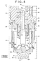
- FIG. 8 is a cross-sectional view showing the state of the portion A of the high-pressure fuel pump when the drive cam further rotates from the state shown in FIG. 7 and the plunger moves downward.
- FIG. 9 is an enlarged cross-sectional view showing the fluid reservoir and its surrounding area of the second embodiment of the invention which corresponds to the B portion in FIG. 4 .
- FIG. 10 is an enlarged cross-sectional view showing the fluid reservoir and its surrounding area of the third embodiment of the invention which corresponds to the portion B in FIG. 4 .
- FIG. 11A is a cross-sectional view taken along the line C-C in FIG. 10
- FIG. 11B is a cross-sectional view taken along the line D-D in FIG. 10 .
- FIG. 12 is an enlarged cross-sectional view showing the fluid reservoir and its surrounding area of the fourth embodiment of the invention which corresponds to the portion B in FIG. 4 .
- FIG. 13 is a cross-sectional view taken along the line E-E in FIG. 12 .
- FIG. 14A is a partially enlarged cross-sectional view showing other embodiment of the fluid reservoir
- FIG. 14B is a cross-sectional view taken along the line F-F in FIG. 14A .
- FIG. 15 is a cross-sectional view of the high-pressure fuel pump of a related art.
- FIG. 16 is an enlarged cross-sectional view of the portion G shown in FIG. 15 .
- a high-pressure pump according to a first embodiment of the invention which is applied to a fuel supply system of an engine will be described with reference to FIGS. 1 to 8 .
- a delivery pipe 12 is connected to each of the fuel injection valves 11 that are provided for the respective cylinders of the engine.
- the delivery pipe 12 serves as a high-pressure fuel pipe and is shared among fuel injection valves 11 , and fuel in the delivery pipe 12 is distributed to each of the fuel injection valves 11 .
- Each of the fuel injection valves 11 is controlled to open and close, whereby high-pressure fuel is directly supplied to the combustion chamber of each cylinder. The fuel injected is then mixed with air in the combustion chamber and air-fuel mixture is thus produced.
- a fuel supply apparatus 13 for supplying high-pressure fuel to the delivery pipe 12 includes a low-pressure fuel pump 15 and a high-pressure fuel pump 17 .
- the low-pressure fuel pump 15 is fixed in a fuel tank 14
- the high-pressure fuel pump 17 is fixed to the engine and connected to the low-pressure fuel pump 15 through a low-pressure fuel passage 16 .
- the low-pressure fuel pump 15 is driven by an electronic motor (not shown) which runs on power supplied from a battery.
- the low-pressure fuel pump 15 pumps fuel 10 up from the fuel tank 14 and discharges the fuel 10 into the low-pressure fuel passage 16 .
- the reference numeral 18 in FIG. 1 denotes a pressure regulator that keeps the fuel pressure (feed pressure) in the low-pressure fuel passage 16 constant.
- the reference numeral 19 denotes a pulsation damper that reduces pulsation of the fuel 10 in the low-pressure fuel passage 19 .
- the high-pressure fuel pump 17 is driven by a camshaft 21 of the engine, and through reciprocation of a plunger 32 , sucks in and pressurizes the fuel 10 distributed from the low-pressure pump 15 through the low-pressure fuel passage 16 .
- a drive cam 22 that drives the high-pressure fuel pump 17 is provided on the camshaft 21 that rotates clockwise.
- the drive cam 22 includes a base circle portion 23 that is shaped like a disc, and a plurality of cam noses 24 that protrude from the base circle portion 23 .
- the high-pressure fuel pump 17 is provided with a bracket 26 having a hole 25 , and is fixed to the cylinder head of the engine by the bracket 26 .
- the hole 25 is located in the proximity of the drive cam 22 , and a lifter guide 27 which has a generally cylindrical shape and has an opening at each end is inserted into the hole 25 .
- One end (the lower end as viewed in FIGS. 2 and 3 ) of a cylinder body 29 is attached to one open end of the lifter guide 27 (the upper open end as viewed in FIGS. 2 and 3 ) through a seat 28 that has a generally cylindrical shape.
- a slide hole 31 having an opening at each end is formed in the cylinder body 29 .
- a centerline L of the slide hole 31 and a rotation center R of the camshaft 21 are on a common plane.
- the plunger 32 is inserted into the slide hole 31 such that it can reciprocate therein.
- a cover 33 covers one end (the upper end as viewed in FIG. 2 ) of the cylinder body 29 .
- the cover 33 is fixed to the bracket 26 by a bolt 34 so that the cylinder body 29 is supported between the cover 33 and the bracket 26 .
- a pressurizing chamber 35 is formed in the cylinder body 29 and is connected to the slide hole 31 .
- the pressuring chamber 35 is also connected to the low-pressure fuel passage 16 so as to allow the fuel 10 discharged from the low-pressure fuel pump 15 to flow into the pressurizing chamber 35 via the low-pressure fuel passage 16 .
- the pressuring chamber 35 is further connected to the delivery pipe 12 through the high-pressure fuel passage 36 (as shown in FIG. 1 ).
- a check valve 37 is provided at a joint portion between the pressuring chamber 35 and the high-pressure fuel passage 36 . The check valve 37 opens only when the pressure of the fuel 10 in the pressurizing chamber 35 exceeds a specified value.
- a lifter 38 which is a cylindrical member closed at the bottom is fit in the lifter guide 27 such that the lifter 38 can reciprocate along the centerline L.
- a portion of the plunger 32 (the lower portion of the plunger 32 as viewed in FIGS. 2 and 3 ) is located in the lifter guide 27 outside the cylinder body 29 .
- a retainer 39 is attached to the outer periphery of the drive cam 22 side end portion of the plunger 32 , and a coil spring 41 is arranged, in a contracted state, between the retainer 39 and the seat 28 . The coil spring 41 presses the plunger 32 against the inner bottom surface of the lifter 38 through the retailer 39 , and thus presses the lifter 38 against the drive cam 22 .
- the position of the plunger 32 in the direction along the centerline L changes as the position of contact between the drive cam 22 and the lifter 38 changes. For example, when the base circle portion 23 of the drive cam 22 contacts the center C of the lifter 38 , the plunger 32 is located closest to the rotation center R of the camshaft 21 within the movable range of the plunger 32 , i.e., at the bottom dead center. At this time, the plunger 32 is located at the farthest position from the pressurizing chamber 35 , and therefore, the capacity of the pressurizing chamber 35 is maximum.
- the plunger 32 is located in the pressurizing chamber 35 side of the bottom dead center within the movable range of the plunger 32 .
- the capacity of the pressurizing chamber gradually increases during the stroke in which the plunger 32 moves from the top dead center to the bottom dead center (intake stroke). Further, the capacity of the pressurizing chamber 35 , as shown in FIG. 6 , gradually decreases during the stroke in which the plunger 32 moves from the bottom dead center to the top dead center (pressurizing stroke).
- the high-pressure fuel pump includes an electromagnetic spill valve 42 that allows and interrupts the communication between the low-pressure fuel passage 16 and the pressurizing chamber 35 .
- the electromagnetic spill valve 42 is fixed to the cover 33 by a bolt 43 .
- the electromagnetic spill valve 42 includes an electromagnetic solenoid. When power is not supplied to the electromagnetic solenoid, the electromagnetic spill valve 42 is open, so the low-pressure fuel passage is connected to the pressurizing chamber 35 . When power is supplied to the electromagnetic solenoid, the electromagnetic spill valve 42 is closed, so the low-pressure fuel passage 16 is shut off from the pressurizing chamber 35 .
- the electromagnetic spill valve 42 is kept opened for the entire intake stroke in which the capacity of the pressurizing chamber 35 increases. Therefore, during an intake stroke, the fuel 10 is introduced from the low-pressure fuel passage 16 to the pressurizing chamber 35 .
- the electromagnetic spill valve 42 is closed at a given timing during a pressurizing stroke in which the capacity of the pressurizing chamber 35 generally decreases.
- On a pressurizing stroke during an open-valve period from when the electromagnetic spill valve 42 is opened to when the valve is closed, the fuel 10 in the pressurizing chamber 35 flows back to the low-pressure fuel passage 16 .
- the check valve 37 opens, discharging the fuel 10 in the pressurizing chamber 35 into the high-pressure fuel passage 36 .
- the timing of closing the electromagnetic spill valve 42 is changed to other within a pressurizing stroke, the amount of fuel 10 that flows back from the pressurizing chamber 35 to the low-pressure fuel passage 16 changes accordingly.
- the amount of fuel 10 discharged from the high-pressure fuel pump 17 can be adjusted by adjusting the close timing of the electromagnetic spill valve 42 .
- the amount of fuel 10 that flows back from the pressurizing chamber 35 to the low-pressure fuel passage 16 during a pressurizing stroke decreases, so that the amount of fuel 10 discharged from the pressurizing chamber 35 to the high-pressure fuel passage 36 during the open-valve period of the electromagnetic spill valve 42 in a pressurizing stroke increases.
- the electromagnetic spill valve 42 is opened when the plunger 32 reaches the bottom dead center, that is, when the plunger stroke switches from an intake stroke to a pressurizing stroke, the overflow amount of fuel 10 becomes minimum, and therefore the amount of fuel 10 discharged from the pressurizing chamber 35 to the high-pressure fuel passage 36 becomes maximum.
- the close timing of the electromagnetic spill valve 42 is delayed through the power supply control of the electromagnetic spill valve 42 , the amount of fuel 10 that flows back from the pressurizing chamber 35 to the low-pressure fuel passage 16 during a pressurizing stroke increases, so that the amount of fuel 10 discharged from the pressurizing chamber 35 to the high-pressure fuel pump 17 during the open-valve period of the electromagnetic spill valve 42 in a pressurizing stroke decreases.
- the close timing of the electromagnetic spill valve 42 is set to or near the bottom dead center of the plunger 32 in order to improve the engine performance. That is, the electromagnetic spill valve 42 is closed when the capacity of the pressurizing chamber 35 becomes maximum or substantially maximum, so that the amount of fuel 10 to be discharged from the high-pressure fuel pump 17 becomes maximum or substantially maximum.
- At least a part of the high-pressure fuel pump 17 is located in the cylinder head, and the oil for lubricating the valve train etc., arranged in the cylinder head is present around the part of the high-pressure fuel pump 17 .
- the contact portion between the drive cam 22 and the lifter 38 is lubricated and cooled by the oil.
- through holes 44 , 45 are formed through the outer peripheral walls of the lifter guide 27 and the lifter 38 , and others, and the oil introduced into the interior of the lifter 38 via the through holes 44 , 45 lubricates and cools the contact portion between the plunger 32 and the inner bottom surface of the lifter 38 .
- the annular space between the plunger 32 and a wall 46 of the slide hole 31 forms a flow passage 47 of the fuel 10 that is discharged from the pressurizing chamber 35 especially when the capacity of the pressurizing chamber 35 is decreasing, i.e., during a pressurizing stroke.
- the fuel 10 lubricates and cools between the plunger 32 and the wall 46 of the slide hole 31 .
- the fuel 10 then flows out from the flow passage 47 at an open end 48 of the slide hole 31 in the drive cam 22 side. Since the oil is present in the lifter 38 as described above, a seal member 49 is attached to the inner peripheral surface of the seat 28 in order to prevent the fuel 10 from being mixed up with the oil.
- the seal member 49 is generally cylindrical, and the end portion of the seal member 49 in the drive cam 22 side (the lower end portion as viewed in FIG. 3 ) closely contacts the outer peripheral surface of the plunger 32 such that the plunger 32 can slide on the seal member 49 .
- the space in the seal member 49 is a reservoir chamber 51 that temporarily stores the fuel 10 that flows through the open end 48 .
- the reservoir chamber 51 is connected to the fuel tank 14 via a return passage 54 (See FIG. 1 ).
- the fuel 10 in the reservoir chamber 51 flows through the return passage 54 and returns to the fuel tank 14 .
- a relief valve 52 is provided for the delivery pipe 12 , and the relief valve 52 is connected to the fuel tank 14 through a relief passage 53 .
- the relief valve 52 is opened when the fuel pressure in the delivery pipe 12 becomes excessively high and exceeds a predetermined level.
- the relief valve 52 is opened, the fuel 10 at high pressure returns to the fuel tank 14 through the relief passage 53 .
- reaction force Fr due to the increase in the pressure of fuel 10 , acts toward the drive cam 22 side, as shown in FIG. 6 .
- pushing force Fu acts from the drive cam 22 toward the pressurizing chamber 35 side.
- a contact point Pa of the drive cam 22 at which it contacts the lifter 38 shifts and deviates from the center C of the lifter 38 as the drive cam 22 rotates.
- pressurizing chamber side end portion Ep pressing force (side force Fs) is exerted from the plunger 32 to an end portion Ep of the slide hole 31 in the pressurizing chamber side (hereinafter, “pressurizing chamber side end portion Ep”) and to an end portion Ed of the slide hole 31 in the drive cam side (hereinafter, “drive cam side end portion Ed”).
- the close timing of the electromagnetic spill valve 42 is set to the bottom dead center of the plunger 32 in order to increase the discharge amount or pressure of fuel 10 so that the engine performance is improved.
- the reaction force Fr caused by the increase in the pressure of fuel 10 increases during the initial period of a pressurizing stroke, and the side force Fs accordingly increases.
- the amount of heat generated by sliding motion of the plunger 32 increases at the pressurizing chamber side end portion Ep and the drive cam side end portion Ed of the slide hole 31 . Therefore, a larger amount of fuel 10 is required to prevent a seizure.
- the pressurizing chamber side end portion Ep Since the volume of fuel 10 in the pressurizing chamber 35 is large, the pressurizing chamber side end portion Ep is lubricated and heat release is promoted. However, the amount of fuel 10 that is supplied to the drive cam side end portion Ed, which is far from the pressurizing chamber side end portion Ep, through the flow passage 47 may not be sufficient, failing to lubricate and cool the drive cam side end portion Ed sufficiently.
- a structure is employed in which a sufficient amount of fuel 10 is supplied to the drive cam side end portion Ed during a pressurizing stroke.
- a fluid reservoir 55 is provided in the flow passage 47 of the fuel 10 at a position that is closer to the pressurizing chamber 35 than the drive cam side end portion Ed of the slide hole 31 is and is near the drive cam side end portion Ed.
- the capacity of the fluid reservoir 55 increases as the plunger 32 moves toward the drive cam 22 , and decreases as the plunger 32 moves toward the pressurizing chamber 35 .
- the slide hole 31 formed in the cylinder body 29 includes a large diameter section 56 in the drive cam 22 side (the lower portion as viewed in the figure) and a small diameter section 57 in the pressurizing chamber 35 side (the upper portion as viewed in the figure).
- the large diameter section 56 and the small diameter section 57 both have circular cross-sections.
- the inner diameter IDd of the large diameter section 56 is set larger than the inner diameter IDp of the small diameter section 57 .
- the boundary between the large diameter section 56 and the small diameter section 57 is a step portion 58 which is annular and perpendicular to the centerline L of the slide hole 31 .
- the step portion 58 is located close to the open end 48 of the slide hole 31 in the drive cam 22 side.
- the plunger 32 includes a large diameter portion 61 and a small diameter portion 62 .
- the large diameter portion 61 is located in the drive cam 22 side, and the small diameter portion 62 is located in pressurizing chamber 35 side.
- the large diameter portion 61 and the small diameter portion 62 have a columnar shape.
- the outer diameter ODp of the small diameter portion 62 is set slightly smaller than the inner diameter IDp of the small diameter section 57 .
- the outer diameter ODd of the large diameter portion 61 is slightly smaller than the inner diameter IDd of the large diameter section 56 and larger than the inner diameter IDp of the small diameter section 57 .
- a deviation ⁇ Dp between the inner diameter IDp and the outer diameter ODp is set substantially equal to a deviation ⁇ Dd between the inner diameter IDd and the outer diameter ODd.
- step portion 63 On the outer peripheral surface of the plunger 32 , the boundary between the small diameter portion 62 and the large diameter portion 61 is a step portion 63 which is annular and is perpendicular to the centerline L.
- the step portion 63 is positioned so as to satisfy the following conditions (i) and (ii).
- the plunger 32 having the aforementioned construction, most part of the small diameter portion 62 is inserted into the small diameter section 57 , and a part of the large diameter portion 61 is inserted into the large diameter section 56 .
- An annular space 64 is formed between the small diameter portion 62 and the small diameter section 57 .
- An annular space 65 is formed between the large diameter portion 61 and the large diameter section 56 .
- the fluid reservoir 55 is the annular space that is surrounded by the walls of the step portions 58 , 63 , the large diameter section 56 , and small diameter portion 62 .
- the fluid reservoir 55 is located close, in the pressuring chamber 35 side, to the drive cam side end portion Ed of the slide hole 31 (i.e. large diameter section 56 ) at which the plunger 32 contacts the wall 46 of the slide hole 31 at the highest surface pressure (as shown in FIG. 6 ). Note that the pressure of the fuel 10 supplied to the drive cam side end portion Ed is higher than that supplied to other portions.
- the plunger 32 is driven by the rotating drive cam 22 to reciprocate in the slide hole 31 . More in detail, during this time, most part of the small diameter portion 62 of the plunger 32 reciprocates in the small diameter section 57 of the slide hole 31 , and part of the large diameter portion 61 reciprocates in the large diameter section 56 .
- the amount of fuel 10 that is equivalent to the amount by which the capacity of the fluid reservoir 55 changes (decreases) as the plunger 32 moves toward the pressurizing chamber 35 is discharged from the fuel reservoir 55 .
- each of the step portion 63 of the plunger 32 and the step portion 58 of the slide hole 31 extends along a plane perpendicular to the centerline L of the slide hole 31 . Therefore, the change in the capacity of the fuel reservoir 55 can be determined as the product of the area of the step portion 58 (or the step portion 63 ) and the distance that the plunger 32 moves.
- the change in the capacity that is, the amount of fuel 10 discharged from the fuel reservoir 55 , is larger than when the fuel reservoir is not provided.
- the drive cam side end portion Ed can be sufficiently lubricated and cooled by the large amount of fuel 10 sent from the fluid reservoir 55 in the aforementioned manner.
- the fluid reservoir 55 is provided in the flow passage 47 of the fuel 10 between the plunger 32 and the wall 46 of the slide hole 31 , and the capacity of the fluid reservoir 55 increases as the plunger 32 moves toward the drive cam 22 , and decreases as the plunger 32 moves toward the pressurizing chamber 35 .
- the fluid reservoir 55 enables a large amount of fuel 10 to be supplied to the portion of the flow passage 47 in the drive cam 22 side of the fluid reservoir 55 . Therefore, even when the plunger 32 inclines in the slide hole 31 and the plunger 32 slides in the slide hole 31 while being pressed against the drive cam side end portion Ed of the wall 46 of the slide hole 31 , the large amount of fuel 10 supplied from the fluid reservoir 55 sufficiently lubricates and cools the drive cam side end portion Ed as described above. As a result, overheating due to the sliding motion of the plunger 32 can be suppressed.
- the slide hole 31 includes the large diameter section 56 in the drive cam 22 side and the small diameter section 57 in the pressurizing chamber 35 side
- the plunger 32 includes the large diameter portion 61 in the drive cam 22 side and the small diameter portion 62 in the pressurizing chamber 35 side, and most part of the small diameter portion 62 is inserted into the small diameter section 57 , and a part of the large diameter portion 61 is inserted into the large diameter section 56 .
- the fluid reservoir 55 is formed by the annular space created between the annular step portion 58 , which is provided between the large diameter section 57 and the small diameter portion 61 , and the annular step portion 63 , which is provided between the large diameter portion 61 and the small diameter portion 62 .
- the capacity of the fluid reservoir 55 increases and decreases as the plunger 32 reciprocates, whereby the fuel 10 is sucked into the fluid reservoir 55 and pressurized therein. Accordingly, the advantage described in (1) can be reliably achieved.
- Each of the step portion 58 of the slide hole 31 and the step portion 63 of the plunger 32 extends along a plane perpendicular to the centerline L of the slide hole 31 .
- the amount of fuel 10 that is equivalent to the amount by which the capacity of the fuel reservoir 55 changes (decreases) as the plunger 32 moves toward the pressurizing chamber 35 is discharged from the fluid reservoir 55 .
- the area of each of the step portions 58 , 63 and the distance that the plunger 32 moves are the elements that determine the amount of fuel 10 to be discharged from the fluid reservoir 55 . Therefore, by adjusting these elements in various manners, the amount of fuel 10 to be discharged from the fluid reservoir 55 can be easily set to the amount necessary for reducing heat due to the sliding motion of the plunger 32 .
- the fluid reservoir 55 is provided close, in the pressurizing chamber 3 side, to the portion where the plunger 32 contacts the wall 46 of the slide hole at the highest surface pressure (the drive cam side end portion Ed). Providing the fluid reservoir 55 at such a position enables the sucking-in and pressurizing of the fuel 10 to be performed near where the plunger 32 slides on the wall 46 of the slide hole 31 at the high surface pressure. Therefore, a large amount of fuel 10 can be supplied at a high pressure to the portion that is subjected to a high surface pressure and a large amount of heat and therefore particularly needs to be cooled and lubricated.
- the step portion 58 of the slide hole 31 and the step portion 63 of the plunger 32 which together define the fluid reservoir 55 , are differently shaped from those in the first embodiment. More specifically, the step portion 58 of the slide hole 31 is tapered such that the diameter of the step portion 58 gradually increases toward the drive cam 22 (downside in FIG. 9 ). Similarly, the step portion 63 of the plunger 32 is tapered such that the diameter of the step portion 63 gradually increases toward the drive cam 22 .
- the degrees of tapering of the step portions 58 , 63 are represented by angles ⁇ 1 , ⁇ 2 , respectively, with respect to the centerline L of the slide hole 31 . The angles ⁇ 1 , ⁇ 2 are set substantially equal to each other.
- the step portion 63 of the plunger 32 is positioned so as to satisfy the conditions (iii), (iv) described below.
- the step portion 58 of the slide hole 31 is tapered such that the inner diameter of the step portion 58 increases toward the drive cam 22 , and therefore the clearance between the step portion 58 and the small diameter portion 62 of the plunger 32 increases toward the drive cam 22 .
- the resistance against the fuel 10 that is discharged from the pressurizing chamber 35 to the fluid reservoir 55 during an intake stroke in which the plunger 32 moves toward the drive cam 22 is smaller than when the step portion 58 is made perpendicular to the centerline L of the slide hole 31 .
- the step portion 63 of the plunger 32 is tapered such that the outer diameter of the step portion 63 increases toward the drive cam 22 , and therefore the clearance between the step portion 63 and the large diameter section 56 of the slide hole 31 decreases toward the drive cam 22 . Therefore, the resistance against the fuel 10 discharged from the fluid reservoir 55 during a pressurizing stroke in which the plunger 32 moves toward the pressurizing chamber 35 is smaller than when the step portion 63 is made perpendicular to the centerline L of the slide hole 31 .
- the step portion 58 of the slide hole 31 is tapered such that the diameter of the step portion 58 gradually increases toward the drive cam 22 . Therefore, the resistance against the fuel 10 flowing into the fluid reservoir 55 during an intake stroke decreases. As a result, the fuel 10 can be efficiently sucked into the fuel reservoir 55 .
- the step portion 63 of the plunger 32 is tapered such that the diameter of the step portion 63 gradually increases toward the drive cam 22 . Therefore, the resistance against the fuel 10 discharged from the fluid reservoir 55 during a pressurizing stroke decreases, which improves the flowability of fuel 10 and thus the lubrication and cooling performances.
- cross-sectional area of the flow passage 47 is different between the space 65 in the drive cam 22 side of the fluid reservoir 55 and the space 64 in the pressurizing chamber 35 side of the fluid reservoir 55 . If the former cross-sectional area is denoted Sd and the latter is denoted Sp, the relationship of Sd>Sp is established.
- the outer diameter ODd of the large diameter portion 61 of the plunger 32 is smaller than that in the first embodiment.
- the deviation ⁇ Dd between the inner diameter IDd of the large diameter section 56 and the outer diameter ODd of the large diameter portion 61 is larger than that in the first embodiment.
- the deviation ⁇ Dp between the inner diameter IDp of the small diameter section 57 and the outer diameter ODp of the small diameter portion 62 is the same as that in the first embodiment. That is, the deviation ⁇ Dd is larger than the deviation ⁇ Dp, and the cross-sectional area Sd of the space 65 in the flow passage 47 is larger than the cross-sectional area Sp of the space 64 in the same passage 47 .
- the structures other than described above are the same as those in the first embodiment. Therefore, the same components and portions as in the first embodiment are denoted by the same reference numerals, and descriptions thereof are omitted.
- the fuel 10 in the fluid reservoir 55 is discharged from the fuel reservoir 55 to either or both of the space 65 in the drive cam 22 side and the space 64 in the pressurizing chamber 35 side. At this time, a larger amount of fuel 10 is discharged from the fluid reservoir 55 to where the flow resistance is smaller, that is, to the space having one of the cross-sectional areas Sd and Sp which is larger than the other. Thus, in the embodiment constructed as above, a larger amount of fuel 10 flows to the space 65 having the cross-sectional area Sd.
- the space 65 includes a portion where, during a pressurizing stroke, the plunger slides on the wall 46 of the slide hole 31 at a high surface pressure and much heat is therefore generated (i.e., a portion around the drive cam side end portion Ed). Therefore, a large amount of fuel 10 is supplied to the drive cam side end portion Ed.
- the following advantage can be obtained in addition to the advantages (1) to (4) described above.
- the cross-sectional area Sd of the space 65 is larger than the cross-sectional area Sp of the space 64 . Therefore, a larger amount of fuel 10 is supplied to the space 65 from the fluid reservoir 55 so as to effectively lubricate and cool the drive cam side end portion Ed.
- FIGS. 12 and 13 A fourth embodiment according to the invention will be described with reference to FIGS. 12 and 13 .
- the space 65 of the fuel passage 47 in the drive cam 22 side of the fluid reservoir 55 is differently formed from the third embodiment.
- the space 65 is divided into “contact side” and “non-contact side” with respect to a plane P extending through the rotation center R of the camshaft 21 and the centerline L of the slide hole 31 .
- the contact side is one side of the space 65 where the drive cam 22 contacts the lifter 38 during a pressurizing stroke (i.e., the left side in FIGS. 12 and 13 ), while the non-contact side is the other side of the space 65 where the drive cam 22 does not contact the lifter 38 (i.e., the right side in FIGS. 12 and 13 ).
- a clearance D 2 in the contact side is set larger than a clearance D 1 in the non-contact side.
- the cross-sectional shape of the large diameter section 56 is non-circular. More specifically, the cross-sectional shape of the large diameter section 56 is semicircular in the non-contact side with respect to the plane P while, in the non-contact side, it is substantially semi-elliptic, so that the cross sectional area of the large diameter portion is larger in the contact side than in the non-contact side.
- the large diameter portion 61 is columnar-shaped as in the third embodiment.
- the two dotted line in FIG. 13 indicates, for comparison, the cross-sectional shape of the large diameter section 56 when it is semicircular also in the contact side.
- the area outside the two-dotted line represents the area where the clearance D 2 is extended.
- the clearance D 1 is constant at any point in the space 65 along its circumferential direction while the clearance D 2 changes such that it is smallest (substantially equal to the clearance D 1 ) in the proximity of the plane P and increases toward the side opposite to the plane P and becomes largest at the point distal from the plane P.
- Either one of the step portion 58 of the slide hole 31 and the step portion 63 of the plunger 32 in the second embodiment may be formed so as to extend along a plane perpendicular to the centerline L of the slide hole 31 .
- the angle ⁇ 1 between the step portion 58 and the centerline L and the angle ⁇ 2 between the step portion 63 the centerline L may be different from each other.
- the step portion 58 of the slide hole 31 and the step portion 63 of the plunger 32 may tapered such that their diameters gradually increase toward the drive cam 22 , as in the second embodiment.
- the fourth embodiment may be modified as follows.
- the cross-sectional shape of the large diameter section 56 is circular as shown in FIGS. 14(A) and 14(B) .
- the centerline of the large diameter section 56 is denoted L 1
- the centerline of the small diameter section 57 is denoted L 2 .
- the large diameter section 56 and the small diameter section 57 are formed such that the centerline L 1 of the large diameter section 56 is offset from the centerline L 2 of the small diameter section 57 .
- the centerline L 1 is offset from the centerline L 2 to the side of the aforementioned plane 9 in which the drive cam 22 contacts the lifter 38 during a pressurizing stroke of the plunger 32 (i.e., the left side in FIGS. 14(A) , 14 (B)).
- the relationship D 2 >D 1 is established between the clearances D 1 , D 2 .
- the invention may be applied to a high-pressure fuel pump in which the electromagnetic spill valve 42 closes a little after the bottom dead center.
- the invention may be applied to a high-pressure pump other than a high-pressure fuel pump of an engine.
- the drive cam 22 may be a drive cam that is provided independent from the camshaft 21 so as to drive the plunger 32 to reciprocate.
Landscapes
- Engineering & Computer Science (AREA)
- Mechanical Engineering (AREA)
- General Engineering & Computer Science (AREA)
- Chemical & Material Sciences (AREA)
- Combustion & Propulsion (AREA)
- Fuel-Injection Apparatus (AREA)
- Details Of Reciprocating Pumps (AREA)
Applications Claiming Priority (2)
| Application Number | Priority Date | Filing Date | Title |
|---|---|---|---|
| JP2005-349731 | 2005-12-02 | ||
| JP2005349731A JP4386030B2 (ja) | 2005-12-02 | 2005-12-02 | 高圧ポンプ |
Publications (2)
| Publication Number | Publication Date |
|---|---|
| US20070128058A1 US20070128058A1 (en) | 2007-06-07 |
| US7794216B2 true US7794216B2 (en) | 2010-09-14 |
Family
ID=38047832
Family Applications (1)
| Application Number | Title | Priority Date | Filing Date |
|---|---|---|---|
| US11/598,005 Expired - Fee Related US7794216B2 (en) | 2005-12-02 | 2006-11-13 | High-pressure pump |
Country Status (4)
| Country | Link |
|---|---|
| US (1) | US7794216B2 (ja) |
| JP (1) | JP4386030B2 (ja) |
| CN (1) | CN1975147B (ja) |
| DE (1) | DE102006056600B4 (ja) |
Cited By (4)
| Publication number | Priority date | Publication date | Assignee | Title |
|---|---|---|---|---|
| RU2605479C2 (ru) * | 2011-12-21 | 2016-12-20 | Роберт Бош Гмбх | Топливный насос |
| US20180017046A1 (en) * | 2011-11-22 | 2018-01-18 | Graco Minnesota Inc. | Box lubrication pump |
| US20180187637A1 (en) * | 2015-06-30 | 2018-07-05 | Denso Corporation | High-pressure pump |
| US10047743B2 (en) | 2013-09-04 | 2018-08-14 | Continental Automotive Gmbh | High pressure pump |
Families Citing this family (17)
| Publication number | Priority date | Publication date | Assignee | Title |
|---|---|---|---|---|
| IT1391096B1 (it) * | 2008-08-05 | 2011-11-18 | Bosch Gmbh Robert | Pompa di alta pressione per alimentare combustibile a un motore a combustione interna |
| JP5642925B2 (ja) * | 2008-08-20 | 2014-12-17 | 日産自動車株式会社 | 高圧燃料ポンプ |
| JP2010127153A (ja) * | 2008-11-26 | 2010-06-10 | Yanmar Co Ltd | 燃料噴射ポンプ |
| US8308450B2 (en) * | 2009-03-05 | 2012-11-13 | Cummins Intellectual Properties, Inc. | High pressure fuel pump with parallel cooling fuel flow |
| EP2278163A1 (en) * | 2009-07-20 | 2011-01-26 | Delphi Technologies Holding S.à.r.l. | Pump assembly |
| US20110052427A1 (en) * | 2009-09-02 | 2011-03-03 | Cummins Intellectual Properties, Inc. | High pressure two-piece plunger pump assembly |
| DE102010001099A1 (de) * | 2010-01-21 | 2011-07-28 | Robert Bosch GmbH, 70469 | Hochdruckpumpe |
| DE102010001880A1 (de) * | 2010-02-12 | 2011-08-18 | Robert Bosch GmbH, 70469 | Zylinderkopf für eine Kraftstoffhochdruckpumpe |
| CN102425533A (zh) * | 2011-09-23 | 2012-04-25 | 重庆工商大学 | 一种正弦流量发生装置 |
| DE102012007125A1 (de) * | 2012-04-07 | 2013-10-10 | Volkswagen Aktiengesellschaft | Radialkolbenpumpe für Kraftstoffförderung |
| DE102013216978A1 (de) * | 2013-08-27 | 2015-03-05 | Robert Bosch Gmbh | Hochdruckpumpe für ein Kraftstoffeinspritzsystem sowie Verfahren zur Herstellung einer Hochdruckpumpe für ein Kraftstoffeinspritzsystem |
| GB201416109D0 (en) * | 2014-09-12 | 2014-10-29 | Delphi International Operations Luxembourg S.�.R.L. | Fuel pump |
| GB201505089D0 (en) * | 2015-03-26 | 2015-05-06 | Delphi International Operations Luxembourg S.�.R.L. | An oil lubricated common rail diesel pump |
| DE102016213727A1 (de) | 2016-07-26 | 2018-02-01 | Bayerische Motoren Werke Aktiengesellschaft | Kraftfahrzeugkraftstoffpumpenabdeckung, Kraftfahrzeugkraftstoffpumpe mit einer solchen Abdeckung und Verfahren zur Herstellung der Abdeckung |
| KR102216495B1 (ko) * | 2017-03-29 | 2021-02-16 | 바르실라 핀랜드 오이 | 내연 피스톤 기관에 연료를 공급하기 위한 연료 펌프 |
| CN107035680A (zh) * | 2017-06-20 | 2017-08-11 | 宁波禄腾精密机械有限公司 | 柱塞结构及柱塞泵 |
| DE102019130684A1 (de) * | 2019-11-14 | 2021-05-20 | Man Energy Solutions Se | Kolbenpumpe |
Citations (13)
| Publication number | Priority date | Publication date | Assignee | Title |
|---|---|---|---|---|
| US2007197A (en) * | 1932-06-06 | 1935-07-09 | Gustav A Carlson | Fuel injection device |
| JPS59194570U (ja) | 1983-06-13 | 1984-12-24 | トヨタ自動車株式会社 | 燃料噴射ポンプ |
| US4776260A (en) * | 1980-11-07 | 1988-10-11 | Vincze Alexander L | Constant pressure pump |
| DE4026689A1 (de) | 1989-08-30 | 1991-03-07 | Waertsilae Diesel Internationa | Einspritzpumpe fuer treibstoff |
| DE69220314T2 (de) | 1991-09-27 | 1998-01-08 | Zexel Corp | Kraftstoffeinspritzpumpe |
| US5984650A (en) * | 1997-06-24 | 1999-11-16 | Unisia Jecs Corporation | Pressure fuel pump device |
| JP2000045907A (ja) | 1998-08-04 | 2000-02-15 | Toyota Motor Corp | 燃料ポンプ |
| JP2001041129A (ja) | 1999-07-27 | 2001-02-13 | Toyota Motor Corp | 高圧ポンプ |
| EP1130250A1 (de) | 2000-03-01 | 2001-09-05 | Wärtsilä NSD Schweiz AG | Saugdrosselpumpe |
| US6394770B1 (en) * | 1999-03-27 | 2002-05-28 | Robert Bosch Gmbh | Piston pump |
| JP2003049745A (ja) | 2001-05-29 | 2003-02-21 | Denso Corp | 燃料噴射ポンプ |
| US6530759B2 (en) * | 2000-04-18 | 2003-03-11 | Toyota Jidosha Kabushiki Kaisha | Reciprocating plunger pump with seal mounting support |
| DE602004001409T2 (de) | 2003-03-14 | 2007-02-08 | Hitachi, Ltd. | Hochdruckpumpe und deren Herstellungsverfahren |
-
2005
- 2005-12-02 JP JP2005349731A patent/JP4386030B2/ja not_active Expired - Fee Related
-
2006
- 2006-11-13 US US11/598,005 patent/US7794216B2/en not_active Expired - Fee Related
- 2006-11-20 CN CN2006101493247A patent/CN1975147B/zh not_active Expired - Fee Related
- 2006-11-30 DE DE102006056600A patent/DE102006056600B4/de not_active Expired - Fee Related
Patent Citations (13)
| Publication number | Priority date | Publication date | Assignee | Title |
|---|---|---|---|---|
| US2007197A (en) * | 1932-06-06 | 1935-07-09 | Gustav A Carlson | Fuel injection device |
| US4776260A (en) * | 1980-11-07 | 1988-10-11 | Vincze Alexander L | Constant pressure pump |
| JPS59194570U (ja) | 1983-06-13 | 1984-12-24 | トヨタ自動車株式会社 | 燃料噴射ポンプ |
| DE4026689A1 (de) | 1989-08-30 | 1991-03-07 | Waertsilae Diesel Internationa | Einspritzpumpe fuer treibstoff |
| DE69220314T2 (de) | 1991-09-27 | 1998-01-08 | Zexel Corp | Kraftstoffeinspritzpumpe |
| US5984650A (en) * | 1997-06-24 | 1999-11-16 | Unisia Jecs Corporation | Pressure fuel pump device |
| JP2000045907A (ja) | 1998-08-04 | 2000-02-15 | Toyota Motor Corp | 燃料ポンプ |
| US6394770B1 (en) * | 1999-03-27 | 2002-05-28 | Robert Bosch Gmbh | Piston pump |
| JP2001041129A (ja) | 1999-07-27 | 2001-02-13 | Toyota Motor Corp | 高圧ポンプ |
| EP1130250A1 (de) | 2000-03-01 | 2001-09-05 | Wärtsilä NSD Schweiz AG | Saugdrosselpumpe |
| US6530759B2 (en) * | 2000-04-18 | 2003-03-11 | Toyota Jidosha Kabushiki Kaisha | Reciprocating plunger pump with seal mounting support |
| JP2003049745A (ja) | 2001-05-29 | 2003-02-21 | Denso Corp | 燃料噴射ポンプ |
| DE602004001409T2 (de) | 2003-03-14 | 2007-02-08 | Hitachi, Ltd. | Hochdruckpumpe und deren Herstellungsverfahren |
Cited By (5)
| Publication number | Priority date | Publication date | Assignee | Title |
|---|---|---|---|---|
| US20180017046A1 (en) * | 2011-11-22 | 2018-01-18 | Graco Minnesota Inc. | Box lubrication pump |
| RU2605479C2 (ru) * | 2011-12-21 | 2016-12-20 | Роберт Бош Гмбх | Топливный насос |
| US10047743B2 (en) | 2013-09-04 | 2018-08-14 | Continental Automotive Gmbh | High pressure pump |
| US20180187637A1 (en) * | 2015-06-30 | 2018-07-05 | Denso Corporation | High-pressure pump |
| US10690098B2 (en) * | 2015-06-30 | 2020-06-23 | Denso Corporation | High-pressure pump |
Also Published As
| Publication number | Publication date |
|---|---|
| US20070128058A1 (en) | 2007-06-07 |
| DE102006056600A1 (de) | 2007-06-06 |
| DE102006056600B4 (de) | 2009-06-04 |
| JP4386030B2 (ja) | 2009-12-16 |
| JP2007154728A (ja) | 2007-06-21 |
| CN1975147A (zh) | 2007-06-06 |
| CN1975147B (zh) | 2010-05-19 |
Similar Documents
| Publication | Publication Date | Title |
|---|---|---|
| US7794216B2 (en) | High-pressure pump | |
| US8382458B2 (en) | High-pressure fuel pump | |
| EP1457667B1 (en) | Fuel supply pump which is lubricated by the fuel | |
| EP1707799A1 (en) | Fuel pump having plunger and fuel supply system using the same | |
| JP5017233B2 (ja) | 高圧燃料ポンプ | |
| JP6380132B2 (ja) | 駆動機構搭載部品 | |
| JP6394413B2 (ja) | 内燃機関の潤滑装置 | |
| JP2006207451A (ja) | 燃料ポンプ及びその燃料ポンプに備えられる吐出弁 | |
| JP2001221131A (ja) | 噴射ポンプのタペット潤滑機構 | |
| JPH10213049A (ja) | 燃料ポンプ | |
| JP2008286124A (ja) | 高圧燃料ポンプ | |
| US7024980B2 (en) | High-pressure fuel pump | |
| US6789459B2 (en) | High-pressure fuel pump | |
| KR20140009580A (ko) | 고압 연료 펌프 조립체 및 펌핑 플런저 | |
| JP2010229914A (ja) | 高圧ポンプ | |
| JP3788373B2 (ja) | 高圧燃料ポンプの給油装置 | |
| JP2010248974A (ja) | 高圧燃料ポンプ | |
| JP2006510835A (ja) | 内燃機関の燃料噴射装置のための高圧ポンプ | |
| JP5218246B2 (ja) | 高圧燃料ポンプ | |
| JP2010001828A (ja) | 高圧燃料ポンプ | |
| JPWO2007083726A1 (ja) | 内燃機関の燃料噴射システム | |
| JP2007177704A (ja) | 高圧ポンプ | |
| JP2008163829A (ja) | 燃料噴射ポンプ | |
| JP3823819B2 (ja) | 燃料噴射ポンプ | |
| JP2001003835A (ja) | 高圧サプライポンプ |
Legal Events
| Date | Code | Title | Description |
|---|---|---|---|
| AS | Assignment |
Owner name: TOYOTA JIDOSHA KABUSHIKI KAISHA, JAPAN Free format text: ASSIGNMENT OF ASSIGNORS INTEREST;ASSIGNOR:KITAMURA, TAKESHI;REEL/FRAME:018565/0615 Effective date: 20060927 |
|
| FEPP | Fee payment procedure |
Free format text: PAYOR NUMBER ASSIGNED (ORIGINAL EVENT CODE: ASPN); ENTITY STATUS OF PATENT OWNER: LARGE ENTITY |
|
| FPAY | Fee payment |
Year of fee payment: 4 |
|
| FEPP | Fee payment procedure |
Free format text: MAINTENANCE FEE REMINDER MAILED (ORIGINAL EVENT CODE: REM.) |
|
| LAPS | Lapse for failure to pay maintenance fees |
Free format text: PATENT EXPIRED FOR FAILURE TO PAY MAINTENANCE FEES (ORIGINAL EVENT CODE: EXP.); ENTITY STATUS OF PATENT OWNER: LARGE ENTITY |
|
| STCH | Information on status: patent discontinuation |
Free format text: PATENT EXPIRED DUE TO NONPAYMENT OF MAINTENANCE FEES UNDER 37 CFR 1.362 |
|
| FP | Lapsed due to failure to pay maintenance fee |
Effective date: 20180914 |