US7593038B2 - Camera enabling panning and moving picture editing program product - Google Patents
Camera enabling panning and moving picture editing program product Download PDFInfo
- Publication number
- US7593038B2 US7593038B2 US11/246,396 US24639605A US7593038B2 US 7593038 B2 US7593038 B2 US 7593038B2 US 24639605 A US24639605 A US 24639605A US 7593038 B2 US7593038 B2 US 7593038B2
- Authority
- US
- United States
- Prior art keywords
- panning
- speed characteristics
- moving picture
- camera
- image
- Prior art date
- Legal status (The legal status is an assumption and is not a legal conclusion. Google has not performed a legal analysis and makes no representation as to the accuracy of the status listed.)
- Expired - Fee Related, expires
Links
- 238000004091 panning Methods 0.000 title claims abstract description 211
- 238000012937 correction Methods 0.000 claims abstract description 68
- 238000004364 calculation method Methods 0.000 claims abstract description 19
- 238000001514 detection method Methods 0.000 claims abstract description 17
- 238000012545 processing Methods 0.000 claims description 48
- 238000006073 displacement reaction Methods 0.000 claims description 17
- 238000000034 method Methods 0.000 claims description 12
- 238000000605 extraction Methods 0.000 claims description 6
- 230000008859 change Effects 0.000 claims description 5
- 239000000284 extract Substances 0.000 claims description 4
- 238000004590 computer program Methods 0.000 claims description 3
- 230000001133 acceleration Effects 0.000 description 18
- 230000005484 gravity Effects 0.000 description 9
- 238000004891 communication Methods 0.000 description 8
- 230000007246 mechanism Effects 0.000 description 7
- 238000005516 engineering process Methods 0.000 description 5
- 239000004973 liquid crystal related substance Substances 0.000 description 5
- 239000000203 mixture Substances 0.000 description 4
- 230000003287 optical effect Effects 0.000 description 3
- 230000003068 static effect Effects 0.000 description 3
- 238000010586 diagram Methods 0.000 description 2
- 230000006870 function Effects 0.000 description 2
- 230000008569 process Effects 0.000 description 2
- 238000006243 chemical reaction Methods 0.000 description 1
- 230000000694 effects Effects 0.000 description 1
- 238000010348 incorporation Methods 0.000 description 1
- 230000001939 inductive effect Effects 0.000 description 1
- 238000005259 measurement Methods 0.000 description 1
- 238000012986 modification Methods 0.000 description 1
- 230000004048 modification Effects 0.000 description 1
- 230000004044 response Effects 0.000 description 1
- 238000009966 trimming Methods 0.000 description 1
Images




Classifications
-
- H—ELECTRICITY
- H04—ELECTRIC COMMUNICATION TECHNIQUE
- H04N—PICTORIAL COMMUNICATION, e.g. TELEVISION
- H04N23/00—Cameras or camera modules comprising electronic image sensors; Control thereof
- H04N23/60—Control of cameras or camera modules
- H04N23/68—Control of cameras or camera modules for stable pick-up of the scene, e.g. compensating for camera body vibrations
-
- H—ELECTRICITY
- H04—ELECTRIC COMMUNICATION TECHNIQUE
- H04N—PICTORIAL COMMUNICATION, e.g. TELEVISION
- H04N23/00—Cameras or camera modules comprising electronic image sensors; Control thereof
- H04N23/60—Control of cameras or camera modules
- H04N23/68—Control of cameras or camera modules for stable pick-up of the scene, e.g. compensating for camera body vibrations
- H04N23/681—Motion detection
- H04N23/6815—Motion detection by distinguishing pan or tilt from motion
-
- H—ELECTRICITY
- H04—ELECTRIC COMMUNICATION TECHNIQUE
- H04N—PICTORIAL COMMUNICATION, e.g. TELEVISION
- H04N23/00—Cameras or camera modules comprising electronic image sensors; Control thereof
- H04N23/60—Control of cameras or camera modules
- H04N23/68—Control of cameras or camera modules for stable pick-up of the scene, e.g. compensating for camera body vibrations
- H04N23/682—Vibration or motion blur correction
- H04N23/685—Vibration or motion blur correction performed by mechanical compensation
- H04N23/687—Vibration or motion blur correction performed by mechanical compensation by shifting the lens or sensor position
Definitions
- the present invention relates to a camera with which moving pictures can be taken, such as a video camera or a digital still camera enabling a moving picture photographing operation that allows a panning operation.
- panning is used to refer to photographing an image over a wide range by moving the camera during the photographing operation, to the left/right, along the upward/downward direction or the like. Such a panning operation is executed either manually or by using a motor-driven pan head.
- Japanese Laid Open Patent Publication No. 2000-261657 discloses a technology whereby the trimming range is automatically adjusted for each frame by tracing a specific photographic subject that is on the move so as to contain it within a central area of the image plane.
- Japanese Laid Open Patent Publication No. 2000-261657 does not assure optimal speed and acceleration in the movement of the image-capturing range during a panning operation performed to sequentially photograph a wide range of landscape or the like.
- the present invention provides a camera with which a smoothly panned moving picture can be obtained by causing the image-capturing range to move with optimal speed and acceleration during a panning operation.
- the present invention also provides a moving picture editing program used to edit a taken moving picture so as to display the moving picture with smooth panning speed characteristics.
- a camera with which a moving picture can be taken by panning the camera comprises: a detection unit that detects actual camera panning speed characteristics; a calculation unit that calculates a speed characteristics difference between the actual panning speed characteristics and reference panning speed characteristics set in advance; and a correction unit that executes correction so as to adjust panning speed characteristics of a moving picture to be obtained closer to the reference panning speed characteristics based upon the speed characteristics difference having been calculated.
- a determining unit that determines the reference panning speed characteristics.
- the detection unit includes an extraction unit that extracts a target point within the moving picture and detects the actual panning speed characteristics based upon an extent of displacement occurring within the moving picture with regard to the target point extracted by the extraction unit.
- a position of the target point is calculated based upon a distance from an end of an image-capturing plane.
- the correction unit includes a cropping unit that crops part of the moving picture, and is capable of altering a position at which the picture is to be cropped by the cropping unit.
- the cropping position is adjusted by altering a read-out position from which a picture is read out from an image-capturing element.
- the reference panning speed characteristics are set as characteristics that demonstrate a specific change over time.
- the detection unit further detects an actual panning direction along which the camera is actually moved;
- the calculation unit further calculates a direction difference between a reference panning direction and the actual panning direction detected by the detection unit; and
- the correction unit executes the correction based upon the direction difference and the speed characteristics difference so as to adjust panning speed characteristics of a moving picture to be obtained along the panning direction closer to the reference panning speed characteristics along the reference panning direction.
- a direction determining unit that determines the reference panning direction.
- the camera according to the 1st aspect it is preferred that: there is further provided an image-capturing unit that captures the moving picture; the correction unit includes a cropping unit that crops part of the moving picture; and the image-capturing unit captures a wider range of picture than a range of the picture having been cropped by the cropping unit.
- the calculation unit calculates an offset extent to which the moving picture becomes offset along a direction perpendicular to the panning direction; and the correction unit corrects the offset of the moving picture manifesting along the direction perpendicular to the panning direction based upon the offset extent having been calculated.
- the computer-readable computer program product contains a program used to edit a moving picture taken by panning a camera.
- the program comprises: detection processing for obtaining the moving picture and detecting actual camera panning speed characteristics based upon the moving picture; calculation processing for calculating a speed characteristics difference between the actual panning speed characteristics and reference panning speed characteristics set in advance; and correction processing for executing correction based upon the speed characteristics difference having been calculated so as to adjust panning speed characteristics of the obtained moving picture closer to the reference panning speed characteristics.
- a picture editing method through which a moving picture taken by panning a camera is edited comprises: obtaining the moving picture taken by panning the camera; calculating a speed characteristics difference between actual camera panning speed characteristics and reference panning speed characteristics set in advance based upon the moving picture having been obtained; and correcting panning speed characteristics of the obtained moving picture based upon the speed characteristics difference having been calculated so as to adjust the panning speed characteristics of the moving picture closer to the reference panning speed characteristics.
- FIG. 1 is a block diagram schematically illustrating the electronic camera achieved in a first embodiment of the present invention with which moving pictures can be taken;
- FIG. 2 presents a flowchart of the panning processing and the correction processing executed in the first embodiment
- FIG. 3 shows how the image plane moves during a panning operation
- FIGS. 4A and 4B show how a coordinate of a target point changes over time
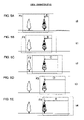
- FIGS. 5A to 5E show the image-obtaining positions at time points t 0 t 1 , t 2 , t 3 and t 4 in an ideal condition
- FIGS. 6A to 6E show the image-obtaining positions at the time points t 0 t 1 , t 2 , t 3 and t 4 in an unstable condition
- FIGS. 7A and 7B illustrate the correction of the image cropping position for the image in the frame F 1 at the time point t 1 ;
- FIG. 8 presents a flowchart of the panning processing and the correction processing executed in a second embodiment
- FIG. 9 shows how the image plane moves during a panning operation relative to a stationary photographic subject
- FIG. 10 shows the images in the individual frames F 1 , F 2 and F 3 captured with the composition shown in FIG. 9 ;
- FIG. 11 illustrates the positional shift of the target point occurring during a panning operation
- FIG. 12 presents an example of images in the frames F 1 , F 2 and F 3 that may be obtained by correcting the images in FIG. 10 ;
- FIG. 13 presents a flowchart of the processing procedure implemented by executing a program for panning speed characteristics and panning direction characteristics correction
- FIG. 14 shows how the moving picture editing program may be provided to a personal computer.
- FIG. 1 is a block diagram schematically illustrating the electronic camera with which dynamic images or moving pictures can be taken, achieved in the first embodiment of the present invention.
- the electronic camera in FIG. 1 includes a photographic lens 1 , an image-capturing device 3 constituted with a CCD image sensor, a CMOS image sensor or the like, an image processor 4 constituted with a CPU 4 a , a memory 4 b and the like, a moving picture shutter release switch 5 , a liquid crystal monitor 6 used as a display device, a camera rotation sensor group 7 that detects the movement of the electronic camera and an image-capturing device moving mechanism 9 .
- a subject image is formed with subject light having passed through the photographic lens 1 .
- the electronic camera achieved in the embodiment may be a video camera exclusively used to take moving pictures or a digital still camera with which moving pictures can be taken.
- the image-capturing device 3 While the power to the electronic camera is in an ON state, the image-capturing device 3 repeatedly and continually captures a subject image.
- the image-capturing device 3 stores a signal charge at each pixel in correspondence to the brightness level of the subject image during the image-capturing operation.
- the stored charges are sequentially discharged from the image-capturing device 3 in response to a drive signal provided to the image-capturing device 3 from a drive circuit (not shown).
- the signal charges first undergo a specific type of analog processing at an analog signal processing circuit (not shown), and then they are converted to digital image-capturing signals at an A/D conversion circuit (not shown) before they are guided to the image processor 4 .
- the image processor 4 provides the image-capturing device 3 with instructions indicating the length of image-capturing period (the length of charge storage period) and the like. In addition, the image processor 4 executes image processing on a digital image-capturing signals, including correction processing executed based upon a reference panning direction to be detailed later as well as white balance adjustment processing and edge compensation processing. Image data resulting from the image processing are recorded into the memory 4 b and are also output to the liquid crystal monitor 6 . As a shutter release operation signal is input thereto from the moving picture shutter release switch 5 , the image processor 4 starts a moving picture photographing sequence and issues an instruction for starting a stored charge discharge at the image-capturing device 3 .
- the camera rotation sensor group 7 which may be constituted with angular speed sensors or acceleration sensors, detects changes ⁇ x and ⁇ y occurring with regard to the photographing direction along the horizontal direction (x direction) and along the direction of gravity (y direction) as the camera rotates. Information indicating the changes in the photographing direction having been detected is provided to the image processor 4 . Based upon signals indicating the changes manifesting along the photographing direction, which have been received from the camera rotation sensor group 7 , the image processor 4 transmits a move signal instructing a move for the image-capturing device 3 to the image-capturing device moving mechanism 9 .
- the camera rotation sensor group 7 may include, for instance, two angular speed sensors to individually detect the angular speed of the camera around the y axis (along the horizontal direction) and the angular speed of the camera around the x axis (along the direction of gravity) relative to the subject. By individually integrating these angular speeds once over each time period t, the rotational angle ⁇ x along the horizontal direction and the rotational angle ⁇ y along the direction of gravity can be calculated.
- the camera rotation sensor group 7 may include three acceleration sensors.
- the angular acceleration in the horizontal direction can be detected based upon the difference between the outputs from the two acceleration sensors disposed side-by-side along the horizontal direction and the angular acceleration in the direction of gravity can be detected based upon the difference between the outputs from two acceleration sensors disposed side-by-side along the direction of gravity in a sensor combination different from the former combination of the acceleration sensors.
- the rotational angle ⁇ x in the horizontal direction and the rotational angle ⁇ y in the direction of gravity can be calculated.
- the image-capturing device moving mechanism 9 includes a drive element such as a piezoelectric element, and is capable of moving the image-capturing device 3 by a very small extent within a plane perpendicular to the optical axis based upon a signal provided by the image processor 4 .
- a drive element such as a piezoelectric element
- images or pictures can be obtained successively over short cycles, e.g., 1/15 sec or 1/30 sec, by adjusting the method with which signals are read out at the image-capturing device 3 . Then, the series of images thus obtained over these short cycles can be saved as a moving picture.
- An explanation is given here on an example in which images are taken in at the rate of a single frame each 1/30 sec.
- FIG. 2 presents a flowchart of the panning processing and the correction processing executed in the first embodiment.
- FIGS. 3 through 7B illustrate the procedure of the correction processing. It is assumed that the user is manually panning the camera fixed to a tripod along the horizontal direction perpendicular to the direction of gravity, to the right in FIGS. 3 through 7B . Since the camera is being panned to the right, the user first sets an image composition at the furthest left end of the range to be photographed. Then, the user starts to pan the camera at a desired speed (desired speed characteristics).
- FIG. 3 shows how the photographic image plane may move relative to a stationary photographic subject during a panning operation.
- a frame F 0 defined by the dotted line on the left side indicates the panning start position
- the frame F 4 defined by the one-point chain line on the right side indicates the panning end position.
- FIG. 3 shows that two trees are photographed as the subject at the panning start position.
- a target point (marked by “X” in FIG. 3 ) is set on a photographic subject within the image plane and any movement of the image plane is detected by detecting the position of the target point within the image plane.
- the camera is panned along the horizontal direction and the coordinate value of the target point taken along the panning direction (x direction) alone is examined.
- FIGS. 4A and 4B show how the coordinate of the target point changes over time.
- the horizontal axis represents the length of time t and the vertical axis represents the coordinate value of the target point taken along the x direction.
- FIG. 4A shows the overall speed characteristics starting at the panning start position and going over to the panning end position.
- FIG. 4B shows in an enlargement part of the speed characteristics achieved over a range near the panning start position.
- the coordinate changes as indicated by the dotted line in FIG. 4A .
- the dotted line in FIG. 4A initially starts to move little by little, accelerates, then achieves a constant speed and gradually decelerates until it stops.
- the solid line in FIG. 4A represents an actual panning operation that may be performed in an unstable condition. While a force is applied to pan the camera up to the time point t 1 , the target point only moves by a very small extent to B′ due to the sliding resistance attributable to the static friction at the pan head. However, once past the time point t 1 , the static friction changes to kinetic friction, thereby lessening the resistance and inducing acceleration. Since an excessive level of force is being applied at this time, the acceleration is also excessive, which displaces the target point all the way to B′′. At this time, the operator reduces the force being applied and attempts to adjust it so as to achieve a constant speed while continuing with the panning operation. However, since the panning operation is performed manually, a certain degree of inconsistency in the speed is inevitable.
- the panning speed is reduced with the force applied gradually reduced.
- the level of force may become insufficient at the point where static friction takes effect, which will result in the speed becoming lower more rapidly than expected by the user. In this situation, the movement may even stop and start. The user pans the camera to the panning end point while readjusting the level of force applied.
- the actual panning characteristics that manifest when a panning operation is performed manually with a camera placed on a pan head are usually unstable, as indicated by the solid line, for the reasons detailed above.
- the panning characteristics resulting from a manual panning operation performed without fixing the camera onto the pan head of a tripod are also unstable, as indicated by the solid line in FIG. 4A , and thus, a smoothly panned moving picture cannot be obtained with ease.
- FIGS. 5A to 5E and FIGS. 6A to 6E indicate the image-obtaining positions assumed at the time points t 0 , t 1 , t 2 , t 3 and t 4 .
- FIGS. 5A to 5E show the image-obtaining positions assumed in an ideal condition (when the speed characteristics indicated by the dotted line in FIG. 4A are achieved), whereas FIGS. 6A to 6E show the image-obtaining positions assumed in an unstable condition (when the speed characteristics are as indicated by the solid line in FIG. 4A ).
- the image-obtaining positions in FIGS. 5A and 6A correspond to the panning start position F 0 in FIG. 3
- the image-obtaining positions in FIGS. 5 E and 6 E correspond to the end position F 4 in FIG. 3 .
- the outer frame defined by the fine dotted line in each figure indicates the range of the image initially obtained by the image-capturing device 3
- the inner frame indicated by the bold dotted line indicates the range of the image in each of the frames F 0 to F 4 ultimately obtained by the image processor 4 . If no correction is executed, the central area of the range of the image initially obtained with the image-capturing device 3 is ultimately obtained by the image processor 4 .
- the coordinate values A to E and A′ to E′ of the target point are each indicated by the distance to the target point from the right end of the range (the range indicated by the bold dotted lines in FIGS. 5A and 5E ) of the image ultimately obtained at the image processor 4 through an ideal panning operation.
- FIGS. 5A to 5E and FIGS. 6A to 6E indicate that while the coordinate of the target point has moved to the position B by the time point t 1 in the ideal condition, as shown in FIG. 5B , the coordinate has only moved to a smaller extent to the coordinate B′, as shown in FIG. 6B in the unstable condition. Accordingly, the following processing is executed to adjust the coordinate of the target point in FIG. 6B closer to the ideal value B.
- the image processor 4 first obtains the image data for the first frame F 0 from the image-capturing device 3 and temporarily saves them into the memory 4 b (step S 301 ). Then, it extracts the coordinate A′ assumed along the x direction by the target point indicated by the “X” mark (positional information indicating the position of the target point within the photographic image plane) from the image data for the first frame F 0 and temporarily saves the coordinate data into the memory 4 b (step S 302 ).
- the target point can be extracted by adopting a face-position decision-making technology or another characteristics extraction technology in the known art.
- the target point can be extracted by extracting an area where the brightness greatly differs from that at nearby pixels or an area where the hue is different from that of nearby pixels within the image and calculating the position of the gravitational center in the area.
- the user may select a target point in an image taken in before taking the moving picture. It is to be noted that the photographic subject containing the target point should be stationary.
- step S 303 When 1/30 sec elapses after photographing the image in the first frame F 0 (step S 303 : YES) the image data for the second frame F 1 are obtained from the image-capturing device 3 and are temporarily saved into the memory 4 b (step S 304 ). Then, with regard to the target point having been extracted in the first frame F 0 its coordinate position in the second frame F 1 is detected (step S 305 ). It is to be noted that if the target point in the preceding frame has moved out of the image-capturing range of the current frame, the coordinate of the target point cannot be detected. In such a case, a new target point contained in both the preceding frame and the current frame is extracted.
- FIGS. 7A and 7B illustrate the correction of the image cropping position for the image in the frame F 1 obtained at the time point t 1 .
- the outermost dotted line indicates the range of the image initially taken in at the image-capturing device 3 .
- the desirable range of the image to be ultimately obtained is indicated by the inner bold dotted line.
- the range over which the image is initially taken in at the image-capturing device 3 is set greater than the ultimate image range since the image plane is bound to be clipped through the cropping.
- the image may be taken in initially over a greater range by, for instance, setting the lens to a slightly wider angle setting.
- the image in the central area of the image range in FIGS. 7A and 7B is ultimately obtained. Accordingly, if the image is obtained at the time point t 1 with the ideal panning speed characteristics determined by the image processor 4 , as shown in FIG. 7B , the target point X is present at the position distanced by B from the right end and, in this case, no correction is required. However, if the image photographed with speed characteristics other than the ideal panning speed characteristics is obtained at the time point t 1 and the central image area indicated by the fine dotted line frame F 1 is cropped, as shown in FIG. 7A , the target point X moves to the position distanced by B′ from the right end.
- the cropping range is moved to the right in the image plane for the image obtained at the time point t 1 in FIG. 7A so as to crop the image over the image range B 1 indicated by the bold dotted line.
- This adjusts the position of the target point X to the position distanced by B from the right end of the image plane, which is the position achieved with the ideal panning speed characteristics.
- the ideal speed characteristics achieved through smooth panning such as those indicated by the dotted line in the graph in FIG. 4A , for instance, are stored. Such speed characteristics may be determined in advance or may be input through a user operation. Based upon the ideal speed characteristics, an ideal displacement B-A to occur during the period elapsing between the time points t 0 and t 1 (see FIGS. 5A and 5B ) is determined, and based upon the ideal displacement, the ideal coordinate value B to be achieved for the target point at the time point t 1 is calculated (step S 308 ).
- the ideal displacement may be estimated based upon the manner with which a plurality of frames of photographed images, including preceding and subsequent frames, move without using a curve obtained in advance, such as that indicated by the dotted line in FIG. 4A .
- the ideal displacement should be estimated based upon the movement in the frames of image shaving been photographed before the image in the correction target frame. If, on the other hand, the image position is to be corrected while editing the image after the photographing operation, the ideal displacement should be estimated based upon the frames of images photographed before and after the image in the correction target frame was photographed.
- the ideal displacement for each frame may be calculated based upon the images in two frames obtained during the panning operation and the number of frames of images photographed in between the two image frames.
- Such ideal speed characteristics are determined by the image processor 4 .
- step S 309 the ideal coordinate B for the target point shown in FIG. 5B is compared with the actual coordinate B′ in FIG. 6B , and if they are different (step S 309 : YES), the image is corrected so as to match the coordinate value of the target point with the ideal coordinate value B. More specifically, by shifting the image cropping position to the right by B-B′, the image is set within the range indicated by the bold dotted line B 1 in FIG. 7A (step S 312 ). This operation is equivalent to displacing the target point to the coordinate position B at an optimal distance from the right end. It is to be noted that if the value of B-B′ is negative, the image cropping position is shifted to the left. The cropping position can be adjusted by, for instance, altering the read start position at which the read of the captured image stored in the memory starts.
- the cropping position may be adjusted by altering the read start position set for the read from the image-capturing element.
- the correction for the detected difference is achieved for the image in the frame obtained directly after the detection. This type of correction with a time lag is particularly effective when the camera is panned slowly.
- an image corrected at a given time point does not need to be cropped from the frame corresponding to the matching time point and may instead be cropped from a frame corresponding to another time point that manifests the closest displacement.
- the displacement C′ in the image photographed for the third frame F 2 in FIG. 6C may be closer to the ideal displacement B than the displacement B′ of the image photographed for the second frame F 1 in FIG. 6B .
- the image shown in FIG. 6C should be used to minimize the extent to which the image is clipped.
- step S 309 NO
- the corrected image in the frame is saved into the memory 4 b and is displayed at the liquid crystal monitor 6 (step S 315 ). Through this process, the moving picture with its panning speed stabilized through the correction processing can be displayed at the liquid crystal monitor 6 in real-time.
- step S 316 a decision is made as to whether or not the moving picture photographing operation has been completed, and if it is decided that the photographing operation has not ended (step S 316 : NO), the operation returns to step S 303 to wait for 1/30 sec to elapse. Subsequently, the frame cropping position is adjusted at each time point so as to ensure that the coordinate position of the target point indicates a change that would occur if the camera were panned smoothly.
- a moving picture is formed by using the series of cropped images.
- the resulting moving picture is substantially identical to an image constituted with the images shown in FIGS. 5A through 5E that are obtained through smooth panning.
- the position of the target point in each of the frames constituting a moving picture is calculated and the characteristics with which the actual position of the target point moves are used as the actual panning speed characteristics.
- the positions assumed by the target point in the individual frames when the camera is panned with the reference panning speed characteristics are calculated as reference positions.
- the difference between an actual position of the target point and the corresponding reference position of the target point along the horizontal direction is used to represent the difference between the actual panning speed characteristics and the reference panning speed characteristics during the image processing.
- a plurality of sets of ideal speed characteristics may be stored in the memory 4 a , the ideal speed characteristics closest to the actual movement characteristics may be extracted (selected) by the image processor 4 and the image-capturing digital signals may then be corrected so as to approximate the extracted ideal speed characteristics. For instance, the ideal speed characteristics closest to the speed calculated in correspondence to B′-A′ in FIGS. 6A and 6B may be extracted from a plurality of sets of ideal speed characteristics and correction processing may be executed based upon these ideal speed characteristics.
- the user may set the ideal speed characteristics to be used for reference through a user operation from a plurality of sets of ideal speed characteristics stored in the memory 4 a . This setting selected by the user is then read and confirmed by the image processor 4 .
- FIG. 8 presents a flowchart of the panning processing and the correction processing executed in the second embodiment.
- FIGS. 9 through 12 illustrate the procedure of the panning direction correction processing, which is part of the correction processing. It is assumed that the user is panning a hand-held camera to the right along the horizontal direction perpendicular to the direction of gravity in FIGS. 9 through 12 . Since the camera is being panned to the right, the user first sets an image composition at the furthest left end of the range to be photographed. Then, the user starts to pan the camera at a desired speed, e.g., at the speed with which the frame moves by an extent equivalent to a single image plane over a four-second period.
- a desired speed e.g., at the speed with which the frame moves by an extent equivalent to a single image plane over a four-second period.
- FIG. 9 shows how the captured image plane moves relative to a stationary subject during a panning operation.
- Rectangles F 1 , F 2 and F 3 defined by dotted lines each indicate the range of the image in a frame captured by the image-capturing device 3 .
- FIG. 10 shows the images in the individual frames F 1 , F 2 and F 3 captured with the compositions shown in FIG. 9 .
- three images are captured by the image-capturing device 3 , as shown in FIG. 10 .
- the image-capturing range shifted diagonally relative to the stationary subject on the image-capturing plane by dx 1 to the right and dy 1 upward.
- the values dx 1 and dy 1 are detected based upon the extent of displacement of the target point on the image data.
- FIG. 11 illustrates the displacement along the vertical direction and the horizontal direction during the panning operation, with the image in the first frame F 1 and the image and the second frame F 2 shown in FIGS. 9 and 10 superimposed so as to align the edges of the individual images.
- the image processor 4 extracts a target point in the first frame F 1 .
- the target point can be extracted by adopting a face-position decision-making technology or another characteristics extraction technology in the known art. For instance, the target point can be extracted by extracting an area where the brightness greatly differs from that at nearby pixels or an area where the hue is different from that of nearby pixels within the image and calculating the position of the gravitational center in the area.
- the user may select an arbitrary target point in an image taken in before photographing the moving picture. It is to be noted that the photographic subject containing the target point should be stationary.
- step S 351 dx 1 and dy 1 representing the extent of displacement of the target points within the image-capturing range, which has occurred between the time point at which the first frame F 1 was photographed and the time point at which the second frame F 2 was photographed, are a calculated.
- FIG. 11 indicates that the target point marked with “X” has moved to the left by dx 1 and has moved down by dy 1 .
- the image processor 4 Since the horizontal direction is set (selected) as the reference panning direction, the image processor 4 is able to let dy 1 represent the extent to which the image is offset relative to the ideal panning direction, i.e., the horizontal direction, and calculate the speed along the horizontal direction based upon dx 1 .
- the horizontal panning speed is now explained. Since a single frame of image is taken in every 1/30 sec, the reference position of the target point within the photographic image plane as the target point moves along the horizontal direction with the reference panning speed characteristics having been set, is calculated every 1/30 sec in step S 352 in the embodiment. The reference position along the vertical direction, too, is calculated in this step. Then, the offset extents (differences) to which the actual position of the target point within the photographic image plane detected every 1/30 sec is offset from the reference position of the target point along the horizontal direction and the vertical direction are calculated (step S 353 ).
- step S 354 image processing is executed on the captured image so that the offset extent dy 1 to which the target point is offset along the vertical direction, having been determined in step S 351 , is reduced to zero and so that the difference between the target point and the reference point manifesting along the horizontal direction, having been calculated in step S 353 , is reduced to zero.
- step S 354 the image is displayed at the monitor in step S 315 , and the processing described above is continuously executed until it is decided in step S 316 that the photographing operation has ended.
- FIG. 12 presents an example of images in the frames F 1 , F 2 and F 3 that may be obtained by correcting the panning direction and the panning speed along both the vertical direction and the horizontal direction for the frame images shown in FIG. 10 .
- the vertical vibration in the moving picture has been corrected by adjusting the upper edges of the individual frames to match the upper edge of the frame F 3 at the lowest position and adjusting the lower edges of the individual frames to match the lower edge of the frame F 2 at the highest position.
- any offset attributable to the speed characteristics along the horizontal direction is corrected.
- the positions of the target point are calculated in correspondence to the individual frames constituting a moving picture and the characteristics with which the actual position of the target point moves are used as panning speed characteristics along the actual panning direction.
- the positions assumed by the target point in the individual frames when the camera is panned with the reference panning speed characteristics along the reference panning direction are calculated as reference positions.
- the difference between an actual position of the target point and the corresponding reference position of the target point along the horizontal direction (the offset quantity) is used to represent the difference between the actual panning speed characteristics and the reference panning speed characteristics and the difference manifesting along the vertical direction is used to represent the difference between the actual panning direction and the reference panning direction.
- the image may appear to have its periphery somewhat clipped off when the offset manifesting along the vertical direction is significant or the deviation of the actual horizontal speed relative to the reference speed is significant, the resulting image, which is panned at the accurate angle, more than makes up for this disadvantage, and it should not become a major problem as long as the camera is used in conjunction with a zoom lens set slightly toward the wide-angle side.
- the entire image should be processed so as to correct the position of the target point in case that the camera is moved along the vertical direction with ideal reference panning speed characteristics based upon the extent to which the target point is offset along the horizontal direction perpendicular to the vertical panning direction and the extent to which the target point is offset from the reference position due to the speed deviation manifesting along the vertical direction.
- image processing should be executed so as to shift the position of the target point to the ideal position in a similar manner.
- the reference panning direction may be stored in advance in the memory 4 a or the reference panning direction setting may be entered by the operator.
- the extent of movement may instead be calculated by adopting another method.
- the angular speed or the acceleration with which the camera rotates may be detected based upon the output from the camera rotation sensor group 7 such as that included in the electronic camera in FIG. 1
- the direction and extent of movement of the image plane may be calculated based upon the angular speed or the acceleration and image processing may be executed based upon the direction and extent of movement of the image plane determined in correspondence to the ideal reference panning speed characteristics along the ideal panning direction.
- the correction may be achieved by adopting another method.
- a mechanism for unsteady hand movement correction may be engaged in operation for the correction, e.g., by moving the image-capturing device 3 to a very small extent with the image-capturing device moving mechanism 9 , by disposing an image blur correction optical system for deflecting the photographing light and minimizing the extent of image blur inside the photographic lens, or by electrically moving the image-capturing range of the image-capturing device so as to adjust the image position on the image-capturing plane.
- correction can be executed substantially in real-time without lowering the image quality or wasting the image data.
- a mechanism can also be used for unsteady hand movement correction. It is to be noted that the differences mentioned earlier should be calculated by utilizing angular speed sensors or the like when a method that requires the image-capturing device to be moved or requires the use of an image blur correction optical system is adopted.
- the correction may instead be executed after the entire photographing operation ends.
- the technology of the present invention can be effective in an application in which photographed image data are read into a personal computer, the panning speed and the panning direction are analyzed by using moving picture editing software or the like, the positions of the individual frames are corrected so as to achieve a panned moving picture with a stable panning speed along a stable panning direction, and the corrected moving pictures are recorded into a recording medium and displayed at a monitor.
- a program used to edit a moving picture photographed while panning the camera enables a computer to execute processing for reading a moving picture (step S 410 ), detection processing for detecting the actual panning speed characteristics and the actual camera panning direction characteristics based upon the moving picture having been read (step S 420 ), calculation processing for calculating the speed characteristics difference between the actual panning speed characteristics and reference panning speed characteristics set in advance and a direction characteristics difference between the actual panning direction characteristics and reference panning direction characteristics set in advance (step S 430 ), and correction processing for correcting the panning speed characteristics and the panning direction characteristics of a moving picture to be obtained by adjusting the characteristics closer to the reference panning speed characteristics and the reference panning direction characteristics based upon the speed characteristics difference and the direction characteristics difference (step S 440 ).
- step S 420 is equivalent to that executed in steps S 302 through S 308 in FIG. 2 and the processing in step S 430 is equivalent to that executed in step S 318 in FIG. 2 .
- the moving picture editing program executed on a personal computer may be provided in a recording medium such as a CD-ROM or as a data signal on the Internet or the like.
- FIG. 14 shows how the program may be provided through such media.
- a personal computer 100 receives the program via a CD-ROM 104 .
- the personal computer 100 has a function which enables it to achieve a connection with a communication line 101 .
- a computer 102 is a server computer that provides the program stored in a recording medium such as a hard disk 103 .
- the communication line 101 may be a communication line for Internet communication, personal computer communication or the like, or it may be a dedicated communication line.
- the computer 102 reads out the program from the hard disk 103 and transmits the program to the personal computer 100 via the communication line 101 .
- the program embodied as a data signal on a carrier wave is transmitted via the communication line 101 .
- the program can be distributed as a computer-readable computer program product adopting any of various modes such as a recording medium and a carrier wave.
- the present invention is not limited to this example.
- the present invention may be adopted in a portable telephone equipped with a camera, with which moving pictures can be taken.
- the present invention may be adopted in all types of image-capturing apparatuses capable of photographing or taking moving pictures.
- the image processor 4 used in the embodiments described above is capable of functioning as the reference panning speed determining means, the actual panning speed characteristics detection means, the calculation means for calculating the difference between the reference panning speed characteristics and the actual panning speed characteristics and the correction means for executing correction based upon the calculation results according to the present invention.
- the explanation provided above simply describes examples, and the present invention may be interpreted without being restricted in any way whatsoever to the correspondence between the components of the embodiments and the components according to the present invention.
Landscapes
- Engineering & Computer Science (AREA)
- Multimedia (AREA)
- Signal Processing (AREA)
- Studio Devices (AREA)
- Image Processing (AREA)
Applications Claiming Priority (2)
| Application Number | Priority Date | Filing Date | Title |
|---|---|---|---|
| JP2004301932A JP4389749B2 (ja) | 2004-10-15 | 2004-10-15 | パンニング撮影可能なカメラおよび動画像編集用プログラム |
| JP2004-301932 | 2004-10-15 |
Publications (2)
| Publication Number | Publication Date |
|---|---|
| US20060082656A1 US20060082656A1 (en) | 2006-04-20 |
| US7593038B2 true US7593038B2 (en) | 2009-09-22 |
Family
ID=36180314
Family Applications (1)
| Application Number | Title | Priority Date | Filing Date |
|---|---|---|---|
| US11/246,396 Expired - Fee Related US7593038B2 (en) | 2004-10-15 | 2005-10-11 | Camera enabling panning and moving picture editing program product |
Country Status (2)
| Country | Link |
|---|---|
| US (1) | US7593038B2 (https=) |
| JP (1) | JP4389749B2 (https=) |
Cited By (4)
| Publication number | Priority date | Publication date | Assignee | Title |
|---|---|---|---|---|
| US20080295023A1 (en) * | 2002-09-30 | 2008-11-27 | Canon Kabushiki Kaisha | Image editing method, image editing apparatus, program for implementing image editing method, and recording medium recording program |
| US20080303916A1 (en) * | 2000-11-15 | 2008-12-11 | Nikon Corporation | Image-capturing device |
| US20090116002A1 (en) * | 2007-11-07 | 2009-05-07 | Konica Minolta Sensing, Inc. | Light quantity measuring apparatus |
| US20090174771A1 (en) * | 2006-01-05 | 2009-07-09 | Mentorwave Technologies Ltd. | Method and apparatus for making a virtual movie for use in exploring a site |
Families Citing this family (16)
| Publication number | Priority date | Publication date | Assignee | Title |
|---|---|---|---|---|
| JP5155145B2 (ja) * | 2006-02-23 | 2013-02-27 | パナソニック株式会社 | 画像補正装置、方法、プログラム、集積回路、システム |
| JP2007311904A (ja) * | 2006-05-16 | 2007-11-29 | Victor Co Of Japan Ltd | ドライブレコーダの映像修正方法、ドライブレコーダ及び、ドライブレコーダシステム |
| JP4828486B2 (ja) * | 2007-08-14 | 2011-11-30 | 富士フイルム株式会社 | デジタルカメラ、撮影方法及び撮影プログラム |
| JP5332438B2 (ja) * | 2008-02-22 | 2013-11-06 | 株式会社リコー | 撮像装置 |
| US8300117B2 (en) * | 2008-03-28 | 2012-10-30 | Fuji Xerox Co., Ltd. | System and method for exposing video-taking heuristics at point of capture |
| JP5117280B2 (ja) * | 2008-05-22 | 2013-01-16 | 富士フイルム株式会社 | 撮像装置、撮像方法、再生装置および再生方法 |
| JP5176857B2 (ja) * | 2008-10-14 | 2013-04-03 | パナソニック株式会社 | 動画編集装置 |
| JP2011091571A (ja) | 2009-10-21 | 2011-05-06 | Olympus Imaging Corp | 動画像作成装置及び動画像作成方法 |
| JP2011155361A (ja) * | 2010-01-26 | 2011-08-11 | Sony Corp | 撮像装置、撮像制御方法、プログラム |
| KR101691156B1 (ko) * | 2010-12-14 | 2016-12-30 | 삼성전자주식회사 | 조명 광학계와 결상 광학계가 통합된 광학계 및 이를 포함하는 3차원 영상 획득 장치 |
| CN105075240B (zh) * | 2013-03-27 | 2018-07-17 | 富士胶片株式会社 | 镜头可换式数码相机 |
| JP6108940B2 (ja) | 2013-04-25 | 2017-04-05 | キヤノン株式会社 | 像振れ補正装置及びその制御方法、プログラム、記憶媒体 |
| JP5880612B2 (ja) * | 2014-03-28 | 2016-03-09 | ブラザー工業株式会社 | 情報処理装置及びプログラム |
| JP7385667B2 (ja) | 2019-09-20 | 2023-11-22 | 富士フイルム株式会社 | 撮影装置、及び撮影方法 |
| JP7576929B2 (ja) * | 2020-06-08 | 2024-11-01 | 株式会社タムロン | 撮像補助装置、撮像補助システム及びその制御方法 |
| US12407790B2 (en) * | 2023-06-13 | 2025-09-02 | Logitech Europe S.A. | Optimal grouping during video conferencing by loss based techniques |
Citations (21)
| Publication number | Priority date | Publication date | Assignee | Title |
|---|---|---|---|---|
| JPH0223789A (ja) | 1988-07-13 | 1990-01-25 | Matsushita Electric Ind Co Ltd | パンニング検出方法及びその装置 |
| JPH0485973U (https=) | 1990-11-29 | 1992-07-27 | ||
| JPH04245782A (ja) | 1991-01-30 | 1992-09-02 | Fuji Photo Film Co Ltd | ビデオカメラ |
| JPH0561091A (ja) | 1991-08-29 | 1993-03-12 | Nikon Corp | ブレ検出可能なカメラ |
| JPH05134284A (ja) | 1991-11-13 | 1993-05-28 | Canon Inc | 画像振れ防止装置 |
| US5416557A (en) | 1989-12-28 | 1995-05-16 | Olympus Optical Co., Ltd. | Camera apparatus having drift detecting unit |
| JPH07226873A (ja) | 1994-02-16 | 1995-08-22 | Hitachi Ltd | 自動追尾撮像装置 |
| US5526045A (en) * | 1983-12-29 | 1996-06-11 | Matsushita Electric Industrial Co., Ltd. | Camera apparatus which automatically corrects image fluctuations |
| JPH08223481A (ja) | 1995-02-16 | 1996-08-30 | Sony Corp | パノラマ静止画像作成装置 |
| JPH10191149A (ja) | 1996-12-27 | 1998-07-21 | Canon Inc | 画像処理装置および方法並びにカメラ一体型vtr |
| JP2000217028A (ja) | 1999-01-26 | 2000-08-04 | Canon Inc | 撮像装置およびその撮像方法 |
| JP2000261657A (ja) | 1999-03-12 | 2000-09-22 | Nippon Telegr & Teleph Corp <Ntt> | 被写体トリミング機能付き編集用映像撮影方法及び装置並びに機能を記述したプログラムを記録した記憶媒体 |
| JP2001339712A (ja) | 2000-05-30 | 2001-12-07 | Ando Electric Co Ltd | 動画監視装置 |
| JP2001359089A (ja) | 2000-06-14 | 2001-12-26 | Sony Corp | 撮影処理装置およびディジタルカメラ |
| US20020039138A1 (en) * | 2000-09-29 | 2002-04-04 | Edelson Steven D. | Method and apparatus for automatically adjusting video panning and zoom rates |
| JP2003198902A (ja) | 2001-12-25 | 2003-07-11 | Sony Corp | パノラマ画像生成装置 |
| JP2004007106A (ja) | 2002-05-31 | 2004-01-08 | Fujitsu Ltd | リモコンシステム |
| JP2004260369A (ja) | 2003-02-25 | 2004-09-16 | Canon Inc | 撮影制御装置 |
| US20060017817A1 (en) * | 2004-07-21 | 2006-01-26 | Mitsumasa Okubo | Image pick-up apparatus and image restoration method |
| US20060017814A1 (en) * | 2004-07-21 | 2006-01-26 | Victor Pinto | Processing of video data to compensate for unintended camera motion between acquired image frames |
| US20060087563A1 (en) * | 2004-10-10 | 2006-04-27 | Dongpu Duan | Method for correcting motion vector errors caused by camera panning |
-
2004
- 2004-10-15 JP JP2004301932A patent/JP4389749B2/ja not_active Expired - Fee Related
-
2005
- 2005-10-11 US US11/246,396 patent/US7593038B2/en not_active Expired - Fee Related
Patent Citations (21)
| Publication number | Priority date | Publication date | Assignee | Title |
|---|---|---|---|---|
| US5526045A (en) * | 1983-12-29 | 1996-06-11 | Matsushita Electric Industrial Co., Ltd. | Camera apparatus which automatically corrects image fluctuations |
| JPH0223789A (ja) | 1988-07-13 | 1990-01-25 | Matsushita Electric Ind Co Ltd | パンニング検出方法及びその装置 |
| US5416557A (en) | 1989-12-28 | 1995-05-16 | Olympus Optical Co., Ltd. | Camera apparatus having drift detecting unit |
| JPH0485973U (https=) | 1990-11-29 | 1992-07-27 | ||
| JPH04245782A (ja) | 1991-01-30 | 1992-09-02 | Fuji Photo Film Co Ltd | ビデオカメラ |
| JPH0561091A (ja) | 1991-08-29 | 1993-03-12 | Nikon Corp | ブレ検出可能なカメラ |
| JPH05134284A (ja) | 1991-11-13 | 1993-05-28 | Canon Inc | 画像振れ防止装置 |
| JPH07226873A (ja) | 1994-02-16 | 1995-08-22 | Hitachi Ltd | 自動追尾撮像装置 |
| JPH08223481A (ja) | 1995-02-16 | 1996-08-30 | Sony Corp | パノラマ静止画像作成装置 |
| JPH10191149A (ja) | 1996-12-27 | 1998-07-21 | Canon Inc | 画像処理装置および方法並びにカメラ一体型vtr |
| JP2000217028A (ja) | 1999-01-26 | 2000-08-04 | Canon Inc | 撮像装置およびその撮像方法 |
| JP2000261657A (ja) | 1999-03-12 | 2000-09-22 | Nippon Telegr & Teleph Corp <Ntt> | 被写体トリミング機能付き編集用映像撮影方法及び装置並びに機能を記述したプログラムを記録した記憶媒体 |
| JP2001339712A (ja) | 2000-05-30 | 2001-12-07 | Ando Electric Co Ltd | 動画監視装置 |
| JP2001359089A (ja) | 2000-06-14 | 2001-12-26 | Sony Corp | 撮影処理装置およびディジタルカメラ |
| US20020039138A1 (en) * | 2000-09-29 | 2002-04-04 | Edelson Steven D. | Method and apparatus for automatically adjusting video panning and zoom rates |
| JP2003198902A (ja) | 2001-12-25 | 2003-07-11 | Sony Corp | パノラマ画像生成装置 |
| JP2004007106A (ja) | 2002-05-31 | 2004-01-08 | Fujitsu Ltd | リモコンシステム |
| JP2004260369A (ja) | 2003-02-25 | 2004-09-16 | Canon Inc | 撮影制御装置 |
| US20060017817A1 (en) * | 2004-07-21 | 2006-01-26 | Mitsumasa Okubo | Image pick-up apparatus and image restoration method |
| US20060017814A1 (en) * | 2004-07-21 | 2006-01-26 | Victor Pinto | Processing of video data to compensate for unintended camera motion between acquired image frames |
| US20060087563A1 (en) * | 2004-10-10 | 2006-04-27 | Dongpu Duan | Method for correcting motion vector errors caused by camera panning |
Cited By (12)
| Publication number | Priority date | Publication date | Assignee | Title |
|---|---|---|---|---|
| US20080303916A1 (en) * | 2000-11-15 | 2008-12-11 | Nikon Corporation | Image-capturing device |
| US20110261230A1 (en) * | 2000-11-15 | 2011-10-27 | Nikon Corporation | Image-capturing device |
| US8655077B2 (en) * | 2000-11-15 | 2014-02-18 | Nikon Corporation | Image-capturing and data extraction device |
| US20080295023A1 (en) * | 2002-09-30 | 2008-11-27 | Canon Kabushiki Kaisha | Image editing method, image editing apparatus, program for implementing image editing method, and recording medium recording program |
| US8112712B2 (en) * | 2002-09-30 | 2012-02-07 | Canon Kabushiki Kaisha | Image editing method, image editing apparatus, program for implementing image editing method, and recording medium recording program |
| US9135733B2 (en) | 2002-09-30 | 2015-09-15 | Canon Kabushiki Kaisha | Image editing method, image editing apparatus, program for implementing image editing method, and recording medium recording program |
| US20090174771A1 (en) * | 2006-01-05 | 2009-07-09 | Mentorwave Technologies Ltd. | Method and apparatus for making a virtual movie for use in exploring a site |
| US8218005B2 (en) * | 2006-01-05 | 2012-07-10 | Google Inc. | Apparatus for making a virtual movie for use in exploring a site |
| US20120229635A1 (en) * | 2006-01-05 | 2012-09-13 | Google Inc. | Method and Apparatus for Making a Virtual Movie for Use in Exploring a Site |
| US8599256B2 (en) * | 2006-01-05 | 2013-12-03 | Google Inc. | Method and apparatus for making a virtual movie for use in exploring a site |
| US20090116002A1 (en) * | 2007-11-07 | 2009-05-07 | Konica Minolta Sensing, Inc. | Light quantity measuring apparatus |
| US7746457B2 (en) * | 2007-11-07 | 2010-06-29 | Konica Minolta Sensing, Inc. | Light quantity measuring apparatus |
Also Published As
| Publication number | Publication date |
|---|---|
| JP4389749B2 (ja) | 2009-12-24 |
| JP2006115323A (ja) | 2006-04-27 |
| US20060082656A1 (en) | 2006-04-20 |
Similar Documents
| Publication | Publication Date | Title |
|---|---|---|
| US7593038B2 (en) | Camera enabling panning and moving picture editing program product | |
| US7830415B2 (en) | Camera having an image stabilizer | |
| US8711230B2 (en) | Image capture apparatus and program | |
| JP6472176B2 (ja) | 撮像装置、像振れ補正装置、撮像装置の制御方法及び像振れ補正方法 | |
| JP4401949B2 (ja) | 動画撮像装置及び動画撮像方法 | |
| US9264651B2 (en) | Moving image reproducing apparatus capable of adjusting display position of indicator for motion analysis based on displacement information of frames, and moving image reproducing method and recording medium for same | |
| CN105391918B (zh) | 图像处理装置及控制图像处理装置的方法 | |
| US9319588B2 (en) | Image capturing apparatus capable of image stabilization during a panning operation and method of controlling the same | |
| US7095001B2 (en) | Image sensing apparatus and method performing blur correction using electrical coordinate conversion | |
| WO2016002355A1 (ja) | 撮影装置及び撮影方法 | |
| US7693406B2 (en) | Image capturing apparatus, method of controlling the same, and storage medium | |
| US9049374B2 (en) | Imaging apparatus with camera shake correction function | |
| JP7625401B2 (ja) | 追尾装置及びその制御方法、及び撮像装置 | |
| JP4517813B2 (ja) | パンニング撮影可能なカメラおよび動画像編集用プログラム | |
| JP2013012978A (ja) | デジタルカメラ | |
| JP2017126960A (ja) | 像ブレ補正装置及びその制御方法、撮像装置、プログラム、記憶媒体 | |
| JP2009171362A (ja) | 撮影装置、撮影方法 | |
| CN110771144B (zh) | 电子设备的控制方法、装置、电子设备及存储介质 | |
| JP2004117195A (ja) | 速度計測機能付デジタルカメラ | |
| JP2007147803A (ja) | 撮像装置、制御方法および制御プログラム | |
| JP2006005417A (ja) | 撮影装置 | |
| JP2007235806A (ja) | 画像処理装置、撮影装置、画像処理方法、および、制御プログラム | |
| JP2007049652A (ja) | カメラ制御システム及びその制御方法並びにプログラム | |
| JP2024010325A (ja) | 評価方法、撮像装置およびプログラム | |
| JP2006229697A (ja) | 撮像装置 |
Legal Events
| Date | Code | Title | Description |
|---|---|---|---|
| AS | Assignment |
Owner name: NIKON CORPORATION, JAPAN Free format text: ASSIGNMENT OF ASSIGNORS INTEREST;ASSIGNOR:OCHIAI, TORU;REEL/FRAME:017079/0033 Effective date: 20051005 |
|
| STCF | Information on status: patent grant |
Free format text: PATENTED CASE |
|
| FEPP | Fee payment procedure |
Free format text: PAYOR NUMBER ASSIGNED (ORIGINAL EVENT CODE: ASPN); ENTITY STATUS OF PATENT OWNER: LARGE ENTITY |
|
| FPAY | Fee payment |
Year of fee payment: 4 |
|
| FPAY | Fee payment |
Year of fee payment: 8 |
|
| FEPP | Fee payment procedure |
Free format text: MAINTENANCE FEE REMINDER MAILED (ORIGINAL EVENT CODE: REM.); ENTITY STATUS OF PATENT OWNER: LARGE ENTITY |
|
| LAPS | Lapse for failure to pay maintenance fees |
Free format text: PATENT EXPIRED FOR FAILURE TO PAY MAINTENANCE FEES (ORIGINAL EVENT CODE: EXP.); ENTITY STATUS OF PATENT OWNER: LARGE ENTITY |
|
| STCH | Information on status: patent discontinuation |
Free format text: PATENT EXPIRED DUE TO NONPAYMENT OF MAINTENANCE FEES UNDER 37 CFR 1.362 |
|
| FP | Lapsed due to failure to pay maintenance fee |
Effective date: 20210922 |