US7578776B1 - Apparatus for changing bits of machine tool - Google Patents
Apparatus for changing bits of machine tool Download PDFInfo
- Publication number
- US7578776B1 US7578776B1 US12/229,007 US22900708A US7578776B1 US 7578776 B1 US7578776 B1 US 7578776B1 US 22900708 A US22900708 A US 22900708A US 7578776 B1 US7578776 B1 US 7578776B1
- Authority
- US
- United States
- Prior art keywords
- bit
- rocker
- machine tool
- cam
- driving unit
- Prior art date
- Legal status (The legal status is an assumption and is not a legal conclusion. Google has not performed a legal analysis and makes no representation as to the accuracy of the status listed.)
- Expired - Fee Related
Links
Images


Classifications
-
- B—PERFORMING OPERATIONS; TRANSPORTING
- B23—MACHINE TOOLS; METAL-WORKING NOT OTHERWISE PROVIDED FOR
- B23Q—DETAILS, COMPONENTS, OR ACCESSORIES FOR MACHINE TOOLS, e.g. ARRANGEMENTS FOR COPYING OR CONTROLLING; MACHINE TOOLS IN GENERAL CHARACTERISED BY THE CONSTRUCTION OF PARTICULAR DETAILS OR COMPONENTS; COMBINATIONS OR ASSOCIATIONS OF METAL-WORKING MACHINES, NOT DIRECTED TO A PARTICULAR RESULT
- B23Q3/00—Devices holding, supporting, or positioning work or tools, of a kind normally removable from the machine
- B23Q3/155—Arrangements for automatic insertion or removal of tools, e.g. combined with manual handling
- B23Q3/157—Arrangements for automatic insertion or removal of tools, e.g. combined with manual handling of rotary tools
- B23Q3/15706—Arrangements for automatic insertion or removal of tools, e.g. combined with manual handling of rotary tools a single tool being inserted in a spindle directly from a storage device, i.e. without using transfer devices
-
- B—PERFORMING OPERATIONS; TRANSPORTING
- B23—MACHINE TOOLS; METAL-WORKING NOT OTHERWISE PROVIDED FOR
- B23Q—DETAILS, COMPONENTS, OR ACCESSORIES FOR MACHINE TOOLS, e.g. ARRANGEMENTS FOR COPYING OR CONTROLLING; MACHINE TOOLS IN GENERAL CHARACTERISED BY THE CONSTRUCTION OF PARTICULAR DETAILS OR COMPONENTS; COMBINATIONS OR ASSOCIATIONS OF METAL-WORKING MACHINES, NOT DIRECTED TO A PARTICULAR RESULT
- B23Q3/00—Devices holding, supporting, or positioning work or tools, of a kind normally removable from the machine
- B23Q3/155—Arrangements for automatic insertion or removal of tools, e.g. combined with manual handling
- B23Q3/1552—Arrangements for automatic insertion or removal of tools, e.g. combined with manual handling parts of devices for automatically inserting or removing tools
- B23Q3/15526—Storage devices; Drive mechanisms therefor
- B23Q3/15534—Magazines mounted on the spindle
-
- Y—GENERAL TAGGING OF NEW TECHNOLOGICAL DEVELOPMENTS; GENERAL TAGGING OF CROSS-SECTIONAL TECHNOLOGIES SPANNING OVER SEVERAL SECTIONS OF THE IPC; TECHNICAL SUBJECTS COVERED BY FORMER USPC CROSS-REFERENCE ART COLLECTIONS [XRACs] AND DIGESTS
- Y10—TECHNICAL SUBJECTS COVERED BY FORMER USPC
- Y10S—TECHNICAL SUBJECTS COVERED BY FORMER USPC CROSS-REFERENCE ART COLLECTIONS [XRACs] AND DIGESTS
- Y10S483/00—Tool changing
- Y10S483/90—Gripping portion engages tool simultanous with tool rotating in spindle
-
- Y—GENERAL TAGGING OF NEW TECHNOLOGICAL DEVELOPMENTS; GENERAL TAGGING OF CROSS-SECTIONAL TECHNOLOGIES SPANNING OVER SEVERAL SECTIONS OF THE IPC; TECHNICAL SUBJECTS COVERED BY FORMER USPC CROSS-REFERENCE ART COLLECTIONS [XRACs] AND DIGESTS
- Y10—TECHNICAL SUBJECTS COVERED BY FORMER USPC
- Y10T—TECHNICAL SUBJECTS COVERED BY FORMER US CLASSIFICATION
- Y10T483/00—Tool changing
- Y10T483/17—Tool changing including machine tool or component
- Y10T483/1733—Rotary spindle machine tool [e.g., milling machine, boring, machine, grinding machine, etc.]
- Y10T483/1748—Tool changer between spindle and matrix
- Y10T483/1752—Tool changer between spindle and matrix including tool holder pivotable about axis
- Y10T483/1755—Plural tool holders pivotable about common axis
-
- Y—GENERAL TAGGING OF NEW TECHNOLOGICAL DEVELOPMENTS; GENERAL TAGGING OF CROSS-SECTIONAL TECHNOLOGIES SPANNING OVER SEVERAL SECTIONS OF THE IPC; TECHNICAL SUBJECTS COVERED BY FORMER USPC CROSS-REFERENCE ART COLLECTIONS [XRACs] AND DIGESTS
- Y10—TECHNICAL SUBJECTS COVERED BY FORMER USPC
- Y10T—TECHNICAL SUBJECTS COVERED BY FORMER US CLASSIFICATION
- Y10T483/00—Tool changing
- Y10T483/17—Tool changing including machine tool or component
- Y10T483/1733—Rotary spindle machine tool [e.g., milling machine, boring, machine, grinding machine, etc.]
- Y10T483/179—Direct tool exchange between spindle and matrix
- Y10T483/1793—Spindle comprises tool changer
- Y10T483/1795—Matrix indexes selected tool to transfer position
Definitions
- the present invention relates to a machine tool and, more particularly, to an apparatus for changing bits of a machine tool.
- a conventional machine tool includes a bit-driving unit 10 and a bit-changing unit.
- the bit-changing unit is used to carry and change holders 24 for holding bits so that a selected one of the bits is engaged with the bit-driving unit 10 .
- the conventional machine tool includes a beam 2 formed thereon, a supporting element 12 connected to the beam 2 and a pinion 11 provided thereon.
- the bit-changing unit includes a rocker 25 connected to the supporting element 12 with a pin 14 and a disc 20 rotationally connected to the rocker 25 .
- a gear 23 is engaged with the pinion 11 and a reduction device 22 is provided between the disc 20 and the gear 23 so that the disc 20 is operated at a low speed as the pinion 11 is operated at a high speed.
- a roller 18 is supported on the rocker 25 and movable against a cam 13 attached to the bit-driving unit 10 .
- the cam 13 includes an upper rectilinear section 15 , a lower rectilinear section 17 and an arched section 16 formed below the upper rectilinear section 15 and the lower rectilinear section 17 .
- a pulling element 26 such as a spring is provided between the rocker 25 and the bit-driving unit 10 . In use, one of the holders 24 is engaged with the bit-driving unit 10 , and the bit-driving unit 10 is located in a lower position where the roller 18 is in contact with the upper rectilinear section 15 of the cam 13 .
- the bit-driving unit 10 is lifted to a middle portion where the roller 18 is in contact with an upper end of the arched section 16 of the cam 13 .
- the pulling element 26 pivots the rocker 25 about the pivot 14 so that one of the clips 21 is moved towards the holder 24 .
- the bit-driving unit 10 is stopped.
- the pulling element 26 further pivots the rocker 25 so that the clip 21 is engaged with the holder 24 , i.e., the clip 21 enters a V-shaped recess defined in the holder 24 .
- the bit-driving unit 10 is lifted to an upper position so that the holder 24 is disengaged from the bit-driving unit 10 .
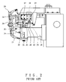
- FIG. 2 there is shown another conventional machine tool including a bit-driving unit 10 and a bit-changing unit.
- the bit-changing unit includes a rocker 25 pivotally connected to the machine tool with a pivot 14 .
- a disc 20 is rotationally connected to the rocker 25 .
- Clips 21 are attached to the disc 20 .
- the clips 21 are used to clip holders 24 .
- a pulling element 26 is provided between the rocker 25 and the machine tool.
- a roller 31 is attached to the rocker 25 .
- a lower track 30 is attached to the bit-driving unit 10 .
- the roller 31 is movable against the lower track 30 .
- An end of the lever 32 is connected to the bit-driving unit 10 .
- a roller 33 is attached to another end of the lever 32 .
- An upper track 34 is attached to the machine tool.
- the upper track 34 includes a groove for receiving the roller 33 so that the lever 32 is pivoted when the roller 33 is rolled in the groove of the upper track 34 as the bit-driving unit 10 is moved vertically.
- a threaded bolt 35 is connected to the lever 32 .
- a nut 36 is engaged with the threaded bolt 36 .
- the nut 36 can be abutted against an element 37 to prevent undesired rotation of an element 38 and the disc 20 .
- a selected one of the clips 21 is movable along an arched path while a related one of the holders 24 is movable along a vertical path.
- the arched path intersects with the vertical path at only a point.
- the selected clip 21 will hit and damage the related holder 24 if the latter is kept in position while the former is moved to the latter.
- the related holder 24 is moved slightly when the selected clip 21 is moved thereto. This requires precise operation of a complicated mechanism.
- the present invention is therefore intended to obviate or at least alleviate the problems encountered in prior art.
- the bit-changing apparatus includes a cam, a rocker, a roller, a linkage, a pulling element, a disc and clips.
- the cam is attached to the machine tool.
- the roller is attached to the rocker and movable against the cam.
- the linkage includes two connecting rods each formed with an end pivotally connected to the machine tool and another end pivotally connected to the rocker.
- the pulling element is provided between the rocker and the machine tool so that the roller is kept against the cam.
- the disc is rotationally supported on the rocker.
- Each of the clips is attached to the disc and used to clip a holder for holding a bit so that a selected bit can be engaged with a bit-driving unit of the machine tool.
- FIG. 1 is a partial side view of a conventional machine tool equipped with a bit-changing apparatus.
- FIG. 2 is a partial side view of another conventional machine tool equipped with a bit-changing apparatus.
- FIG. 3 is a side view of a bit-changing apparatus according to the preferred embodiment of the present invention.
- FIG. 4 is side view of the bit-changing apparatus in another position than shown in FIG. 3 .
- FIGS. 5 through 7 are partial side views of a machine tool equipped with the bit-changing apparatus shown in FIG. 3 .
- a machine tool is equipped with a bit-changing apparatus according to the preferred embodiment of the present invention.
- the machine tool includes a post 1 , a beam 2 connected to the post 1 , a supporting element 12 attached to the beam 2 and a bit-driving unit 10 vertically movable thereon.
- the bit-changing unit is used to carry and change holders 24 for holding bits so that a selected one of the bits can be engaged with the bit-driving unit 10 .
- the bit-changing unit includes a cam 13 attached to the bit-driving unit 10 , a linkage 50 connected to the supporting element 12 , a rocker 25 connected to the linkage 50 and a disc 20 rotationally connected to the rocker 25 .
- a reduction device 22 is connected to the disc 20 so that the disc 20 is operated at a low speed.
- the cam 13 is formed with an upper rectilinear section 15 , a lower rectilinear section 17 and a curved section 16 between the upper rectilinear section 15 and the lower rectilinear section 17 .
- a roller 40 is attached to a lower end of the rocker 25 and movable against the cam 13 attached to the bit-driving unit 10 .
- a pulling element 26 is provided between the rocker 25 and the bit-driving unit 10 so that the roller 40 is retained against the cam 13 .
- the pulling element 26 is preferably a spring.
- the linkage 50 includes two connecting rods 51 and 52 .
- An end of the connecting rod 51 is pivotally connected to the supporting element 12 with a pivot 53 while another end of the connecting rod 51 is pivotally connected to the rocker 25 with a pivot 54 .
- An end of the connecting rod 52 is pivotally connected to the supporting element 12 with a pivot 55 while another end of the connecting rod 52 is pivotally connected to the rocker 25 with a pivot 56 .
- the roller 40 is rolled against the curved section 16 of the cam 13 as the pivot 54 is moved along an arched path 57 while the pivot 56 is moved along an arched path 59 .
- the connecting rod 51 is pivoted by an angle A while the connecting rod 52 is pivoted by an angle B.
- the angle A is larger than the angle B.
- a phantom line 58 between the axes of the pivots 54 and 56 is pivoted.
- the curved section 16 of the cam 13 is substantially horizontal.
- one of the holders 24 (the “current holder 24 ”) is engaged with the bit-driving unit 10 .
- the bit-driving unit 10 is in a position where the roller 40 is in contact with the upper rectilinear section 15 of the cam 13 .
- the bit-driving unit 10 is lifted.
- the angle of the rocker 25 is not changed as the roller 40 rolls on the upper rectilinear section 15 of the cam 13 .
- the roller 40 reaches a first end of the arched section 16 of the cam 13 , and the lifting of the bit-driving unit 10 is stopped.
- the pulling element 26 causes the rocker 25 to move so that the roller 40 moves to a second end of the arched section 16 of the cam 13 as shown in FIG. 6 .
- the connecting rods 51 and 52 are pivoted about the pivots 53 and 55 , respectively.
- the movement of the roller 40 along the curved section 16 of the cam 13 is substantially horizontal so that the movement of a selected one of the clips 21 is substantially horizontal.
- the engagement of the clip 21 with the current holder 24 is smooth and gentle. Therefore, the hit and damage of the holder 24 by the clip 21 is mild.
- bit-driving unit 10 in a second phase of the lifting of the bit-driving unit 10 , the bit-driving unit 10 is disengaged from the current holder 24 while the current holder 24 is engaged with the clip 21 .
- the disc 20 is rotated on the rocker 25 so that the new holder 24 is moved near the bit-driving unit 10 .
- the bit-driving unit 10 is lowered so that the new holder 24 is engaged with the bit-driving unit 10 .
- the foregoing process is reversed so that the related clip 21 is disengaged from the new holder 24 .
Priority Applications (2)
| Application Number | Priority Date | Filing Date | Title |
|---|---|---|---|
| US12/229,007 US7578776B1 (en) | 2008-08-19 | 2008-08-19 | Apparatus for changing bits of machine tool |
| CN2009201654178U CN201483275U (zh) | 2008-08-19 | 2009-08-13 | 加工机换刀机构的刀库固定装置 |
Applications Claiming Priority (1)
| Application Number | Priority Date | Filing Date | Title |
|---|---|---|---|
| US12/229,007 US7578776B1 (en) | 2008-08-19 | 2008-08-19 | Apparatus for changing bits of machine tool |
Publications (1)
| Publication Number | Publication Date |
|---|---|
| US7578776B1 true US7578776B1 (en) | 2009-08-25 |
Family
ID=40973376
Family Applications (1)
| Application Number | Title | Priority Date | Filing Date |
|---|---|---|---|
| US12/229,007 Expired - Fee Related US7578776B1 (en) | 2008-08-19 | 2008-08-19 | Apparatus for changing bits of machine tool |
Country Status (2)
| Country | Link |
|---|---|
| US (1) | US7578776B1 (zh) |
| CN (1) | CN201483275U (zh) |
Cited By (8)
| Publication number | Priority date | Publication date | Assignee | Title |
|---|---|---|---|---|
| US20120241342A1 (en) * | 2011-03-24 | 2012-09-27 | Ying Sun | Tool magazine |
| US20130345034A1 (en) * | 2012-06-25 | 2013-12-26 | Yi-Jun Liu | Fast Tool Changing System by Means of Synchronizing Displacement and Linkage of Main Spindle and Tool Magazine |
| US20140256527A1 (en) * | 2013-03-11 | 2014-09-11 | Kugi Tech Corp. | Tool changer for machine tool |
| CN104070399A (zh) * | 2013-03-28 | 2014-10-01 | 兄弟工业株式会社 | 机床 |
| US20150072845A1 (en) * | 2013-09-11 | 2015-03-12 | Fanuc Corporation | Tool changer for machine tool |
| CN105750970A (zh) * | 2016-04-26 | 2016-07-13 | 东莞市永钰精密机械有限公司 | 一种刀库设于主轴架上的龙门机床 |
| EP3208035A4 (en) * | 2014-10-18 | 2018-07-11 | Horkos Corporation | Horizontal machine tool |
| JP2020154382A (ja) * | 2019-03-18 | 2020-09-24 | ブラザー工業株式会社 | 数値制御装置、数値制御プログラム、及び、数値制御プログラムを記憶した記憶装置 |
Families Citing this family (5)
| Publication number | Priority date | Publication date | Assignee | Title |
|---|---|---|---|---|
| CN102729082B (zh) * | 2011-04-12 | 2014-09-03 | 孙颖 | 加工机械的刀具交换装置 |
| CN102528509A (zh) * | 2012-02-08 | 2012-07-04 | 昆山北钜机械有限公司 | 中心加工机刀库机构 |
| CN103240602A (zh) * | 2012-02-13 | 2013-08-14 | 上海莱必泰精密机电有限公司 | 数控高速钻铣装置 |
| JP5956040B1 (ja) * | 2015-09-07 | 2016-07-20 | Dmg森精機株式会社 | 工作機械 |
| CN107175535B (zh) * | 2017-05-05 | 2019-04-26 | 大连机床(数控)股份有限公司 | 换刀防护门平面联动机构 |
Citations (6)
| Publication number | Priority date | Publication date | Assignee | Title |
|---|---|---|---|---|
| US4813122A (en) * | 1984-01-20 | 1989-03-21 | Brother Kogyo Kabushiki Kaisha | Machine tool |
| US4873756A (en) * | 1986-02-05 | 1989-10-17 | Brother Kogyo Kabushiki Kaisha | Machine tool |
| US5499963A (en) * | 1992-01-29 | 1996-03-19 | Fanuc Ltd. | Automatic tool changer |
| US20050009679A1 (en) * | 2003-07-07 | 2005-01-13 | Fanuc Ltd | Automatic tool changing device for machine tool |
| US20060094575A1 (en) * | 2004-10-29 | 2006-05-04 | Fanuc Ltd Of | Automatic tool changer |
| US20070225139A1 (en) * | 2006-03-27 | 2007-09-27 | Fanuc Ltd | Automatic tool changing method and device for machine tool controlled by numerical controller |
-
2008
- 2008-08-19 US US12/229,007 patent/US7578776B1/en not_active Expired - Fee Related
-
2009
- 2009-08-13 CN CN2009201654178U patent/CN201483275U/zh not_active Expired - Fee Related
Patent Citations (8)
| Publication number | Priority date | Publication date | Assignee | Title |
|---|---|---|---|---|
| US4813122A (en) * | 1984-01-20 | 1989-03-21 | Brother Kogyo Kabushiki Kaisha | Machine tool |
| US4873756A (en) * | 1986-02-05 | 1989-10-17 | Brother Kogyo Kabushiki Kaisha | Machine tool |
| US5499963A (en) * | 1992-01-29 | 1996-03-19 | Fanuc Ltd. | Automatic tool changer |
| US20050009679A1 (en) * | 2003-07-07 | 2005-01-13 | Fanuc Ltd | Automatic tool changing device for machine tool |
| US20060094575A1 (en) * | 2004-10-29 | 2006-05-04 | Fanuc Ltd Of | Automatic tool changer |
| US7300393B2 (en) * | 2004-10-29 | 2007-11-27 | Fanuc Ltd | Automatic tool changer |
| US20070225139A1 (en) * | 2006-03-27 | 2007-09-27 | Fanuc Ltd | Automatic tool changing method and device for machine tool controlled by numerical controller |
| US7445587B2 (en) * | 2006-03-27 | 2008-11-04 | Fanuc Ltd | Automatic tool changing method and device for machine tool controlled by numerical controller |
Cited By (12)
| Publication number | Priority date | Publication date | Assignee | Title |
|---|---|---|---|---|
| US20120241342A1 (en) * | 2011-03-24 | 2012-09-27 | Ying Sun | Tool magazine |
| US8652018B2 (en) * | 2011-03-24 | 2014-02-18 | Ying Sun | Tool magazine |
| US20130345034A1 (en) * | 2012-06-25 | 2013-12-26 | Yi-Jun Liu | Fast Tool Changing System by Means of Synchronizing Displacement and Linkage of Main Spindle and Tool Magazine |
| US20140256527A1 (en) * | 2013-03-11 | 2014-09-11 | Kugi Tech Corp. | Tool changer for machine tool |
| US9050695B2 (en) * | 2013-03-11 | 2015-06-09 | Kugi Tech Corp. | Tool changer for machine tool |
| CN104070399A (zh) * | 2013-03-28 | 2014-10-01 | 兄弟工业株式会社 | 机床 |
| US20150072845A1 (en) * | 2013-09-11 | 2015-03-12 | Fanuc Corporation | Tool changer for machine tool |
| US9339905B2 (en) * | 2013-09-11 | 2016-05-17 | Fanuc Corporation | Tool changer for machine tool |
| EP3208035A4 (en) * | 2014-10-18 | 2018-07-11 | Horkos Corporation | Horizontal machine tool |
| CN105750970A (zh) * | 2016-04-26 | 2016-07-13 | 东莞市永钰精密机械有限公司 | 一种刀库设于主轴架上的龙门机床 |
| CN105750970B (zh) * | 2016-04-26 | 2018-06-05 | 东莞市永钰精密机械有限公司 | 一种刀库设于主轴架上的龙门机床 |
| JP2020154382A (ja) * | 2019-03-18 | 2020-09-24 | ブラザー工業株式会社 | 数値制御装置、数値制御プログラム、及び、数値制御プログラムを記憶した記憶装置 |
Also Published As
| Publication number | Publication date |
|---|---|
| CN201483275U (zh) | 2010-05-26 |
Similar Documents
| Publication | Publication Date | Title |
|---|---|---|
| US7578776B1 (en) | Apparatus for changing bits of machine tool | |
| US7575542B1 (en) | Apparatus for changing bits of machine tool | |
| CN205600331U (zh) | 用于钢管加工的夹具 | |
| KR102130446B1 (ko) | 마스크 프레임 어셈블리 제조용 간격 조절형 대형 듀얼 그리퍼 장치 | |
| CN207174882U (zh) | 一种可移动调节的自动夹持装置 | |
| FR2467041A1 (fr) | Appareil d'ebavurage pour brames coulees en continu | |
| JP4395657B2 (ja) | 補助ローラ | |
| US9421652B2 (en) | Center frame of CNC machine tool | |
| EP3842163B1 (fr) | Machine et procede de cintrage | |
| CN200967089Y (zh) | 一种自动定心中心架 | |
| JP6570881B2 (ja) | 工作機械のカバー開閉装置 | |
| CN106219998B (zh) | 一种具有玻璃基板阻挡装置的镀膜模板机构 | |
| CN109606834A (zh) | 包装机上袋机构 | |
| CN214352282U (zh) | 一种稳定式高度调节垫块 | |
| US1247341A (en) | Drill. | |
| CN110497486B (zh) | 一种木板开槽机 | |
| CN210547623U (zh) | 一种精密变压器成型弯线装置 | |
| CN210476006U (zh) | 一种异形铝棒对焊机夹具 | |
| JP4245541B2 (ja) | キャップチップ取外し装置 | |
| US3043360A (en) | Forming machines | |
| US1904493A (en) | Transfer mechanism | |
| KR20100027861A (ko) | 공작기계의 비트변경장치 | |
| JPH02116446A (ja) | 鋼管等の送り込み装置 | |
| JP2008229771A (ja) | 工具交換装置 | |
| CN106435469B (zh) | 一种具有倾斜平移组合式自动闭合门的镀膜箱 |
Legal Events
| Date | Code | Title | Description |
|---|---|---|---|
| FPAY | Fee payment |
Year of fee payment: 4 |
|
| REMI | Maintenance fee reminder mailed | ||
| LAPS | Lapse for failure to pay maintenance fees |
Free format text: PATENT EXPIRED FOR FAILURE TO PAY MAINTENANCE FEES (ORIGINAL EVENT CODE: EXP.) |
|
| STCH | Information on status: patent discontinuation |
Free format text: PATENT EXPIRED DUE TO NONPAYMENT OF MAINTENANCE FEES UNDER 37 CFR 1.362 |
|
| FP | Lapsed due to failure to pay maintenance fee |
Effective date: 20170825 |