US7540679B2 - Variable grip structure - Google Patents
Variable grip structure Download PDFInfo
- Publication number
- US7540679B2 US7540679B2 US10/531,924 US53192405A US7540679B2 US 7540679 B2 US7540679 B2 US 7540679B2 US 53192405 A US53192405 A US 53192405A US 7540679 B2 US7540679 B2 US 7540679B2
- Authority
- US
- United States
- Prior art keywords
- grip
- finger
- shaft
- rearward
- structure according
- Prior art date
- Legal status (The legal status is an assumption and is not a legal conclusion. Google has not performed a legal analysis and makes no representation as to the accuracy of the status listed.)
- Expired - Fee Related, expires
Links
Images




Classifications
-
- B—PERFORMING OPERATIONS; TRANSPORTING
- B43—WRITING OR DRAWING IMPLEMENTS; BUREAU ACCESSORIES
- B43K—IMPLEMENTS FOR WRITING OR DRAWING
- B43K24/00—Mechanisms for selecting, projecting, retracting or locking writing units
- B43K24/02—Mechanisms for selecting, projecting, retracting or locking writing units for locking a single writing unit in only fully projected or retracted positions
- B43K24/08—Mechanisms for selecting, projecting, retracting or locking writing units for locking a single writing unit in only fully projected or retracted positions operated by push-buttons
- B43K24/084—Mechanisms for selecting, projecting, retracting or locking writing units for locking a single writing unit in only fully projected or retracted positions operated by push-buttons with saw-like or analogous cams
-
- B—PERFORMING OPERATIONS; TRANSPORTING
- B43—WRITING OR DRAWING IMPLEMENTS; BUREAU ACCESSORIES
- B43K—IMPLEMENTS FOR WRITING OR DRAWING
- B43K23/00—Holders or connectors for writing implements; Means for protecting the writing-points
- B43K23/008—Holders comprising finger grips
-
- B—PERFORMING OPERATIONS; TRANSPORTING
- B25—HAND TOOLS; PORTABLE POWER-DRIVEN TOOLS; MANIPULATORS
- B25G—HANDLES FOR HAND IMPLEMENTS
- B25G1/00—Handle constructions
-
- B—PERFORMING OPERATIONS; TRANSPORTING
- B43—WRITING OR DRAWING IMPLEMENTS; BUREAU ACCESSORIES
- B43K—IMPLEMENTS FOR WRITING OR DRAWING
- B43K3/00—Nib holders
Definitions
- the present invention relates to a grip structure having a grip portion consisting of an elastic member.
- examples of those having such a grip include writing tools such as mechanical pencils, ball-point pens and whiteout (eraser) pens, cutting tools such as snap-off blade knives, chisels and screw drivers, input pens for use in personal digital assistants (PDAs) and electronic notebooks, and bicycle handle bars.
- the grip portion can be expanded or contracted in the radial direction, it still left room for further development.
- the expansion or contraction takes place uniformly in the circumferential direction, specific fingers are caused to feel unpleasant.
- a writing tool is usually gripped with three fingers including the thumb, index finger and middle finger. If, however, the grip portion is expanded (contracted) and adjusted mainly on the basis of the thumb, the index finger and middle finger will feel unpleasant.
- the present invention essentially permits an elastic member and a shaft body which fixes the elastic member to be rotatable relative to each other and provides means for keeping their relative rotating actions, and is intended to enable each of various users gripping the object to select a state in which he or she can sense the best feeling of gripping.
- variable grip structure characterized in that it has an elastic member and a shaft body fixing the elastic member, which are rotatable relative to each other, and means for keeping their relative rotating actions.
- the sectional shape of the elastic member can be made a deformed shape.
- slits or grooves can also be formed in the direction of the length of the external face of the elastic member.
- the hardness of the elastic member can also be made partially different.
- the surface roughness of the elastic member can also be made partially different and varied.
- the elastic member is configured of a base material and a non-base material
- the non-base material area is partially provided in the base material
- the hardness of the non-base material area is made greater than the hardness of the base material
- the sectional shape of the engaging portion and engagement receptacle portion can be T-shaped.
- the engaging portion and engagement receptacle portion can also be formed in a direction perpendicular to the direction of the length of the shaft body.
- ribs which are engaged with and disengaged from each other can also be formed on the internal faces or the external faces of the forward member and rear member rotating relative to each other.
- a restricting part can also be provided to restrict in the rotating directions of the forward member and rear member rotating relative to each other.
- variable grip structure for a writing tool, wherein the cylindrical body of the writing tool has a grip body composed by coupling in series a substantially cylindrical elastic member between a forward shaft constituting the cylindrical body and a rear shaft,
- the forward end of the elastic member is fixed to the rear end of the forward shaft
- a rotational mechanism is provided in the serially coupled grip body to enable the forward shaft and the rear shaft to rotate relative to each other and to be stopped in a prescribed rotational position.
- variable grip structure a concave portion and a convex portion are formed in a twisted state in the grip portion deformed by rotation, and fingers can be positioned on the twisted concave portion.
- the angle of twist can be selectively adjusted by each individual user as he or she likes. As the grip portion is extended or contracted by the twisting operation, the hardness of the grip portion can be varied according to the angle of twist.
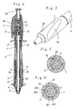
- FIG. 1 is an external view showing an example in which a variable grip structure according to the invention is used in a writing tool
- FIG. 2 is an external view showing an action of the grip structure of FIG. 1 ;
- FIG. 3 is a perspective view showing the essential part of FIG. 2 ;
- FIG. 4 shows a longitudinal section of FIG. 1 ;
- FIG. 5 shows a section of a variation of the method of fixing a grip portion to a forward shaft
- FIG. 6 shows a section along line A-A in FIG. 4 ;
- FIG. 7 shows a section along line B-B arrowed in FIG. 4 ;
- FIG. 8 shows a longitudinal section of the essential part of a variation of means for keeping rotating actions
- FIG. 9 shows a longitudinal section of the essential part of another variation of means for keeping rotating actions
- FIG. 10 shows a section along line C-C arrowed in FIG. 9 ;
- FIG. 11 shows a longitudinal section of still another variation of means for keeping rotating actions
- FIG. 12 is an exploded perspective view showing the essential part of FIG. 11 ;
- FIG. 13 is an external view showing of a variation of the grip portion
- FIG. 14 shows a cross section of an example before the action shown in FIG. 13 ;
- FIG. 15 is an external view showing another variation of the grip portion
- FIG. 16 shows a section along line D-D in FIG. 15 ;
- FIG. 17 is an external perspective view showing still another variation of the grip portion
- FIG. 18 shows a longitudinal section of a variation of the means of fixing the grip portion to the shaft body
- FIG. 19 shows a section along line E-E in FIG. 18 ;
- FIG. 20 shows a section along line F-F in FIG. 18 ;
- FIG. 21 is an exploded perspective view showing the essential part of FIG. 18 ;
- FIG. 22 shows a longitudinal section of shows a longitudinal section of a variation of the means of fixing the grip portion to the shaft body
- FIG. 23 shows a section along line G-G in FIG. 22 ;
- FIG. 24 is an exploded perspective view showing the essential part of FIG. 22 ;
- FIG. 25 is an exploded perspective view showing the essential part of the variation of the means of fixing the grip portion to the shaft body.
- FIG. 1 is an external view showing a case that there is no rotation of an elastic member relative to a shaft body.
- Reference numeral 1 denotes a grip portion made of a soft elastic member (elastic finger-grip member), and the grip portion 1 has a hollow portion 1 c .
- the grip portion 1 is disposed around and encircles the shaft body.
- the forward end side (the lower side in the drawing) of the grip portion 1 is unrotatably (non-rotatably) fixed to a forward shaft (forward member) 2 .
- the rear end side (the upper side in the drawing) of the grip portion 1 is also unrotatably fixed to a middle shaft (rear member) 3 .
- Its rear or rearward shaft 4 though unrotatably fixed to the forward shaft 2 via a linking member 7 , is rotatably arranged relative to the middle shaft 3 . Therefore, when the middle shaft 3 and rear shaft 4 are held with fingers or the like and rotated relative to each other, the forward shaft 2 rotates together with the rear shaft 4 by way of the linking member 7 ( FIG. 4 ). This causes the grip portion 1 to be rotationally deformed in a twisted state ( FIG. 2 ).
- the forward, middle and rearward shafts 2 , 3 , 4 constitute shaft portions that are arranged in series to form a shaft body.
- a plurality of recesses such as grooves 1 a
- a plurality of projections such as stubs 2 a
- a plurality of grooves la are also formed in the rear part of the inside of the grip portion 1 , and engaged with a plurality of stubs 2 a formed outside the middle shaft 3 , resulting in unrotatable fixation of the other (rear) end of the grip portion 1 to the middle shaft 3 .
- the means of fixing the grip portion 1 to the forward shaft 2 and to the middle shaft 3 are not limited to grooves (or stubs) 1 a formed at the two ends of the grip portion 1 and stubs (or grooves) 2 a formed on (in) the forward shaft 2 and the middle shaft 3 to engage with the grooves 1 a , but other suitable fixing means or method as an adhesive, thermal fusion, ultrasonic deposition, caulking or press-fitting may be used.
- FIG. 6 An example of such variation is shown in FIG. 6 and will be described.
- a plurality of T-shaped grooves 1 b are formed at the forward end of the inside the grip portion 1 , and a plurality of T-shaped stubs 2 b formed in the rear part of the forward shaft 2 engage with these T-shaped grooves 1 b in an inserted state.
- the forward part of the grip portion 1 is unrotatably fixed to the forward shaft 2 .
- the T-shape intends to mean and include a configuration in which a wider groove 1 b 1 (or stub 2 b 1 protruding from the forward shaft 2 ) is formed in a part distal to the shaft center in the cross section and a narrower groove 1 b 2 (or stub 2 b 1 protruding from the forward shaft 2 ) in a part proximal to the shaft center.
- this embodiment is a retractable writing tool having a ball-point pen 6 in a shaft body, a mechanical pencil, a solid correcting tool or the like may be disposed as well.
- a gap 16 is formed between the middle shaft 3 and the linking member 7 , and a friction ring 8 which consists of a soft member and whose sectional shape is rectangular, circular or oval is formed in the gap 16 to provide a frictional resistance force against the relative rotation of the middle shaft 3 and the linking member 7 .
- a frictional resistance force in the rotating direction is provided so that the restoring action of the grip portion 1 is prevented when the middle shaft 3 and the grip portion 1 are rotated relative to each other.
- the friction ring 8 obstructs the restoring action occurring when the grip is twisted.
- the internal face in which the ring 8 is positioned from the rear end of the middle shaft 3 is in a conical shape, slightly expanding the part in which the ring 8 is positioned toward the rear end.
- the retracting mechanism in this embodiment uses a so-called David cam mechanism (rotational cam mechanism) configured of a cam cylinder 9 , a rotor 10 , a slider 11 , a knocking member 11 a fixed to that slider 11 , a cam spring 12 , a forward spring 13 and so forth
- a retracting mechanism may, for instance, use clip manipulation or be a screwing-out mechanism.
- the writing tool may as well have no retracting mechanism, and be fitted with a cap covering the writing part. Since this retracting mechanism is well known by a structure which makes the writing tip retractable by knocking, for instance by knocking the rear end, it is supposed to be as illustrated ( FIG. 4 ) and its detailed description will be dispensed with.
- a plurality of finger-contact portions such as concave portions 1 d are formed in the surface of the grip portion 1 , and the concave portions 1 d are coated with a rubber-like paint whose surface is relatively smooth, but the concave portions 1 d may as well be molded as another member and partially embedded into the grip portion 1 .
- the concave portions 1 d may be molded integrally by such means as two-colored molding.
- the two parts may be the same in hardness but different in color, or differentiated in hardness, but where they are to be differentiated in hardness, it is preferable for the concave portions 1 d to be greater in hardness. More specifically, it is preferable for the concave portions 1 d , with which fingers are to come into contact, to be 50 to 70 in Shore hardness and for other parts to be 20 to 50 in Shore hardness.
- typical materials for the grip portion 1 include silicone rubber, nitrile butadiene rubber, natural rubber, styrene rubber, styrene butadiene rubber, butadiene rubber, chloroprene rubber and urethane rubber, the choice is not limited to these, but the material can also be selected from various other alternatives.
- each may as well be differentiated in surface roughness from others. This differentiation may be achieved through coating as described or by such means as two-colored molding. More specifically, it is preferable for the surface of the concave 1 d , namely the part with which fingers are to come into contact, to be shaped relatively rough and those of other parts to be relatively smooth. The anti-slip effect would be enhanced and an improved feeling of grip can be expected.
- arciform rotational engaging grooves 3 a are partially formed in the inner circumferential face of the middle shaft 3
- arciform stubs 7 a partially formed on the outer circumferential face of the linking member 7 are engaged with the rotational engaging grooves 3 a .
- the contact and engagement of these rotational engaging groove 3 a and stubs 7 a prevent the middle shaft 3 and the rear shaft 4 (the grip portion 1 ) from rotating excessively, and rotational deforming stress is thereby prevented from working on the grip portion 1 more than necessary.
- Rotation of the middle shaft 3 and the rear shaft 4 relative to each other by about 90 degrees in one direction causes the stubs 7 a of the linking member 7 to come into contact with ends of the rotational engaging grooves 3 a in the middle shaft 3 to restrict the relative rotation in this embodiment, but this rotational angle (range) can be set as appropriate.
- An internal step 3 b is formed on the inner circumferential face of the middle shaft 3 .
- an external step 7 b is formed on the outer circumferential face of the linking member 7 .
- the ring 8 whose section consists of a circular soft member. Crimping of the ring 8 provides frictional resistance against the relative rotation of the middle shaft 3 and the linking member 7 .
- typical materials for the ring 8 in the foregoing example and this example include rubber-like elastic materials such as silicone rubber, nitrile butadiene rubber, natural rubber, styrene rubber, styrene butadiene rubber, butadiene rubber, chloroprene rubber and urethane rubber, the material can as well be selected from such soft resin materials as polyethylene, polypropylene and polyethylene terephthalate.
- FIG. 9 and FIG. 10 is another variation of the way of providing a frictional resistance force against the relative rotation of the middle shaft 3 and the linking member 7 .
- a plurality of undulating ribs 3 c are formed on the inner circumferential face of the middle shaft 3 .
- undulating engaging ribs 7 c which can be engaged with or disengaged from and can override the ribs 3 c are formed on the outer circumferential face of the linking member 7 . The engagement of these ribs 3 c and engaging ribs 7 c maintains the rotational deformation of the grip portion 1 by a restoring force.
- the grip portion 1 when the grip portion 1 is rotationally deformed, the grip portion 1 is also extended in the lengthwise direction, and its substantive hardness increases and at the same time a stress to restore it from the extension also occurs. This may give rise to a gap in the joint between the forward shaft 2 (the middle shaft 3 ) and the grip portion 1 . In order to prevent this gap, each shaft can be fixed to the grip portion by adhesion or thermal fusion. Instead, the grip portion 1 may be formed longer than the fitting portion of the shaft cylinder 1 , and the grip portion 1 in a state of compression in the lengthwise direction may be fitted to the middle shaft 3 .
- a forward shaft 14 and a rear shaft 15 are rotatably linked to each other to constitute the shaft body.
- the linking member 7 in the foregoing example is not used with a view to reducing the production cost.
- the rear end of the grip portion 1 is fixed to the middle part of the rear shaft 15
- the forward end of the grip portion 1 is fixed to the forward part of the forward shaft 14 .
- a twist is produced to the grip portion 1 .
- a plurality of ribs 14 a and 15 a which slidably contact each other, are radially formed at the rear end of the rear shaft 15 and the forward end of the forward shaft 14 . Further, the rear shaft 15 and the forward shaft 14 are urged toward each other all the time to keep the ribs 14 a and the ribs 15 a in contact with each other. The urging force is achieved as the grip portion 1 , which is fixed to both the forward shaft 14 and the rear shaft 15 , draws one shaft toward the other. Thus, in this embodiment the rear shaft 15 is fixed to the forward shaft 14 in a state that the grip portion 1 is extended beyond its natural length.
- the aforementioned urging force may be brought to act by another means or member, such as a coil spring or some other springy member.
- a relative rotation between the rear shaft 15 and the forward shaft 14 will make their respective ribs 14 a and 15 a override each other thereby to rotationally deform or twist the grip portion 1 and, at the time the overriding is completed, the deformed, twisted shape is maintained.
- Reference numerals 14 b and 15 b denote T-shaped stubs which, like their counterparts in the foregoing examples, are inserted into, for engagement with, T-shaped grooves in the grip portion 1 (for instance, the T-shaped grooves 2 b , shown in FIG. 4 and FIG. 6 ).
- the concave portion 1 d consisting of a recessed arc is formed in the grip portion 1 in the foregoing embodiments to facilitate fitting of the concave portion 1 d to the gripping fingers when rotational deformation has been achieved to an appropriate extent
- the specific shape of the grip portion can be selected as appropriate.
- a shape is shown in FIG. 13 through FIG. 15 for instance. Though it is a stripe shape of a substantially hexagonal column extending in the longitudinal direction in a state that the grip portion 1 is not rotationally deformed (see FIG. 14 ), it is deformed into a spiral stripe once it is rotationally deformed (see FIG. 13 ).
- a convex portion 1 e and a concave portion 1 d are formed on and in the stripe-deformed grip portion 1 .
- FIG. 15 and FIG. 16 are also desirous.
- the grip portion 1 maintains a substantially cylindrical shape in section when it is not rotationally deformed. Once it is rotationally deformed, it varies into a shape whose central portion is flat (flat portion 1 f ) (see FIG. 15 and FIG. 16 ).
- the grip portion 1 has many grooves 1 g which are formed in the longitudinal direction when it is not rotationally deformed.
- the grooves 1 g are deformed in spiral rotation when it is subjected to rotational deformation.
- a shape of the grip portion matching the preference of, or more suitable for, the user who holds the grip portion can be easily obtained by appropriate and selective rotational deformation.
- the shaft cylinder is composed of a rear shaft cylinder 17 , a middle shaft cylinder 18 and a forward shaft cylinder 19 .
- the rear shaft cylinder 17 and the middle shaft cylinder 18 are unrotatably coupled to be unable to come off in the lengthwise direction while pinching between them an engaging step portion 20 d of a grip 20 .
- the middle shaft cylinder 18 and the forward shaft cylinder 19 though rotatable relative to each other around the central axis of the shaft cylinder, are coupled to be unable to come off in the lengthwise direction.
- Ahead of the forward shaft cylinder 19 there are formed a plurality of longitudinally extending stubs 19 a whose section is substantially arciform partially, and they are inserted into respectively matching ones of holes 20 a which are formed in a forward part of the inside of the grip 20 and have substantially the same shape in section.
- These stubs 19 a and holes 20 a may instead be in three or five positions even in only one position, but preferably they should be formed in about four positions.
- Tapered faces 19 e are formed at the tips of the stubs 19 a to facilitate their insertion into the holes 20 a .
- an end piece 21 is fitted to the forward end of the forward shaft cylinder 19 , and this end piece 21 is detachably fitted with a screw mechanism.
- a plurality of stubs 17 a which extend in the direction of the length of the shaft cylinder and whose section is either elliptic or substantially arciform in part are formed ahead of the rear shaft cylinder 17 , and they are inserted into respectively matching ones of holes 20 b which are formed in the rear end face 20 f of the grip 20 and whose section has substantially the same shape as the stubs 17 a .
- a reduced-diameter part 18 g is formed in the rear part of the middle shaft cylinder 18 , and rear flat portions 18 e are provided in two opposite positions on the reduced-diameter part 18 g .
- a protruding part 18 c which is greater than the reduced-diameter part 18 g in diameter.
- an outer diameter part 18 f of a greater diameter is formed in the linking part between the middle shaft cylinder 18 and the reduced-diameter part 18 g , and an engaging step portion 18 b is formed as a result of the formation of the outer diameter part 18 f .
- a reduced-diameter part is formed in the rear part of the inside of the grip 20 , and an engaging step portion 20 d is formed as a result of the formation of this reduced-diameter part.
- middle shaft cylinder 18 and the rear shaft cylinder 17 are unrotatably coupled by the engagement of their respective flat portions 18 e and flat portions 17 c , and longitudinally releasable by the engagement of the larger-diameter protruding part 18 c of the middle shaft cylinder 18 with the matching larger diameter part 17 d of the rear shaft.
- the rear part of the grip 20 is also made unrotatable relative to the middle shaft cylinder 18 (and the rear shaft cylinder 17 ) and coupled to be unable to come off in the lengthwise direction.
- a reduced-diameter part 19 f is formed on the rear external face of the forward shaft cylinder 19 , and a plurality of arciform stubs 19 b which extend in the lengthwise direction are formed all over around the reduced-diameter part 19 f .
- grooves 18 a whose section is arciform are formed all over the internal face of the middle shaft cylinder 18 and in the lengthwise direction.
- the number of the stubs 19 b of the forward shaft cylinder 19 and that of the grooves 18 a of the middle shaft cylinder 18 are equal, and the stubs 19 b and the grooves 18 a are engaged with each other.
- Reference numeral 19 c denotes an engaging step portion which links the middle shaft cylinder 18 and the forward shaft cylinder 19 .
- the grip 20 tries to restore its form from the rotationally deformed state, but the engagement between the holes 20 a of the grip 20 and the stubs 19 a of the forward shaft cylinder 19 and the aforementioned coupling of the rear part of the grip 20 with the middle shaft cylinder 18 and the rear shaft cylinder 17 maintain the rotationally deformed shape.
- a plurality of holes 20 c substantially orthogonal to the direction of the length of the shaft cylinder are formed in a side face of a reduced-diameter part 20 g covered by the rear shaft cylinder 17 behind the grip 20 , while stubs 18 d which is in a snap-fit engagement with the holes 20 c are formed behind the middle shaft cylinder 18 .
- the middle shaft cylinder 18 is unrotatably coupled to the rear shaft cylinder 17 in a state engagement with the holes 20 c of the grip 20 such that the cylinders 17 and 18 are unreleasable in the lengthwise direction and unable to come off.
- the engaging step portion 18 b of the middle shaft cylinder 18 and the forward end face 17 b of the rear shaft cylinder 17 are held in a pinching way between the engaging step portion 20 d formed in the rear part of the inside of the grip 20 and an engaging step portion 20 h formed in the rear part of the outside of the grip 20 .
- the configuration is the same as in the foregoing examples in respect of other elements, which will only be denoted by reference numerals in the drawings but whose detailed description will be dispensed with.
- FIG. 25 Still another example of variation will be described with reference to FIG. 25 .
- a plurality of holes 20 e extending substantially in parallel to the direction of the length of the shaft cylinder are formed, and the holes 20 e are engaged with a plurality of stubs formed behind the middle shaft cylinder 18 .
- the configuration is the same as in the foregoing examples in respect of other elements, whose detailed description will be dispensed with.
- the plurality of the holes 20 e of the grip 20 in this embodiment are blocked on the rear side, their rear ends may be open, namely they may be through holes, for the convenience of molding.
- the present invention by virtue of its structure and its actions described so far, can solve the problems noted above and provide an excellent variable grip structure.
- an elastic member and a shaft body to which the elastic member is fixed are designed to be relatively rotatable and suitable means for keeping their relative rotating actions is provided, adaptation is made possible by the relative rotation of those shaft body and elastic member to the hand size and preference of the user, which may vary individually from one user to the other.
- these can be achieved by a relatively simple component configuration.
Landscapes
- Engineering & Computer Science (AREA)
- Mechanical Engineering (AREA)
- Pens And Brushes (AREA)
- Toys (AREA)
- Passenger Equipment (AREA)
- Manipulator (AREA)
- Mechanical Pencils And Projecting And Retracting Systems Therefor, And Multi-System Writing Instruments (AREA)
- Fishing Rods (AREA)
Applications Claiming Priority (3)
| Application Number | Priority Date | Filing Date | Title |
|---|---|---|---|
| JP2002308332A JP2004142191A (ja) | 2002-10-23 | 2002-10-23 | 可変式グリップ構造 |
| JP2002-308332 | 2002-10-23 | ||
| PCT/JP2003/013413 WO2004037552A1 (ja) | 2002-10-23 | 2003-10-21 | 可変式グリップ構造 |
Publications (2)
| Publication Number | Publication Date |
|---|---|
| US20060045604A1 US20060045604A1 (en) | 2006-03-02 |
| US7540679B2 true US7540679B2 (en) | 2009-06-02 |
Family
ID=32170971
Family Applications (1)
| Application Number | Title | Priority Date | Filing Date |
|---|---|---|---|
| US10/531,924 Expired - Fee Related US7540679B2 (en) | 2002-10-23 | 2003-10-21 | Variable grip structure |
Country Status (11)
| Country | Link |
|---|---|
| US (1) | US7540679B2 (de) |
| EP (1) | EP1557290A4 (de) |
| JP (1) | JP2004142191A (de) |
| KR (1) | KR20050051716A (de) |
| CN (1) | CN100402316C (de) |
| AU (1) | AU2003301543A1 (de) |
| BR (1) | BR0315501A (de) |
| CA (1) | CA2499705A1 (de) |
| MX (1) | MXPA05004337A (de) |
| TW (1) | TW200410840A (de) |
| WO (1) | WO2004037552A1 (de) |
Cited By (4)
| Publication number | Priority date | Publication date | Assignee | Title |
|---|---|---|---|---|
| US20070154253A1 (en) * | 2006-01-03 | 2007-07-05 | Kotobuki & Co., Ltd. | Writing instrument |
| US10406849B1 (en) * | 2019-02-07 | 2019-09-10 | Khaled A. M. A. A. Al-Khulaifi | Training pen for writing |
| US20200023508A1 (en) * | 2018-07-18 | 2020-01-23 | Ideal Industries, Inc. | Tool having an auto-adjusting handle |
| EP4424472A1 (de) * | 2023-03-01 | 2024-09-04 | Husqvarna AB | Werkzeug |
Families Citing this family (20)
| Publication number | Priority date | Publication date | Assignee | Title |
|---|---|---|---|---|
| US20060062628A1 (en) * | 2004-09-20 | 2006-03-23 | Ken Kostecki | Deformable grip for a writing implement |
| JP4555657B2 (ja) * | 2004-10-15 | 2010-10-06 | ミクロ株式会社 | 筆記具 |
| CN100427326C (zh) * | 2005-09-26 | 2008-10-22 | 贝发集团股份有限公司 | 一种笔杆 |
| US7708903B2 (en) | 2005-11-01 | 2010-05-04 | E.I. Du Pont De Nemours And Company | Compositions comprising fluoroolefins and uses thereof |
| USD559314S1 (en) * | 2006-04-26 | 2008-01-08 | Beifa Group Co., Ltd. | Pen |
| USD591345S1 (en) | 2007-10-17 | 2009-04-28 | Beifa Group Co., Ltd. | Pen |
| JP5134405B2 (ja) * | 2008-03-17 | 2013-01-30 | アスベル株式会社 | 電子レンジ用調理容器 |
| JP5551539B2 (ja) * | 2010-07-29 | 2014-07-16 | 三菱鉛筆株式会社 | 筆記具 |
| FR2995246B1 (fr) * | 2012-09-11 | 2014-09-05 | Bic Soc | Instrument d'ecriture ergonomique et versatile |
| US20140253519A1 (en) * | 2013-03-08 | 2014-09-11 | Michael David | Expandable diameter stylus |
| US9304610B2 (en) * | 2013-05-20 | 2016-04-05 | Lenovo (Singapore) Pte. Ltd. | Expanding pen for information handling device |
| US10073544B2 (en) * | 2015-10-14 | 2018-09-11 | Microsoft Technology Licensing, Llc | Stylus with adjustable grip diameter |
| USD797497S1 (en) * | 2016-01-27 | 2017-09-19 | Runway Blue, Llc | Container with lid |
| US10185409B2 (en) | 2016-03-15 | 2019-01-22 | Microsoft Technology Licensing, Llc | Stylus with an adjustable dimension |
| JP6707375B2 (ja) * | 2016-03-22 | 2020-06-10 | 株式会社パイロットコーポレーション | 筆記具 |
| US20180229538A1 (en) * | 2017-02-15 | 2018-08-16 | Perry Kaye | Methods and Apparatuses for Pigment Application and Removal |
| US10754447B2 (en) * | 2018-01-10 | 2020-08-25 | Microsoft Technology Licensing, Llc | Stylus capsule |
| TWI720386B (zh) * | 2018-12-14 | 2021-03-01 | 林亞勳 | 動態矯正握筆姿勢的書寫工具 |
| WO2022170261A1 (en) * | 2021-02-08 | 2022-08-11 | WeCool Toys Inc. | Uv-light drawing activity |
| JP7839623B2 (ja) | 2021-09-14 | 2026-04-02 | セーラー万年筆株式会社 | 筆記具 |
Citations (7)
| Publication number | Priority date | Publication date | Assignee | Title |
|---|---|---|---|---|
| JPS4851434A (de) | 1971-10-30 | 1973-07-19 | ||
| JPS5976378A (ja) | 1982-10-25 | 1984-05-01 | 日本鋼管株式会社 | 二重殻タンクの施工法 |
| US5263275A (en) * | 1992-04-10 | 1993-11-23 | Berkley, Inc. | Variable circumference rod handle |
| JP2607456B2 (ja) | 1984-05-14 | 1997-05-07 | 株式会社東芝 | 磁気記録用磁性粉及びその製造方法 |
| JPH09169194A (ja) | 1995-12-19 | 1997-06-30 | Pentel Kk | 筆記具のグリップ |
| JP2000313193A (ja) | 1999-04-22 | 2000-11-14 | Atx Internatl Inc | 外面可変グリップ |
| JP2001001681A (ja) | 1999-06-22 | 2001-01-09 | Yoshimasa Kojima | 筆記具およびその製造方法 |
Family Cites Families (9)
| Publication number | Priority date | Publication date | Assignee | Title |
|---|---|---|---|---|
| JPS4516087Y1 (de) * | 1965-08-16 | 1970-07-04 | ||
| US3730238A (en) * | 1971-09-21 | 1973-05-01 | R Butler | Friction type screwdriver |
| JPS4851434U (de) * | 1971-10-19 | 1973-07-04 | ||
| JPS5976378U (ja) * | 1982-11-15 | 1984-05-23 | 大塚工機株式会社 | 握り部の軸径が変わる筆記具 |
| US5056945A (en) * | 1990-09-04 | 1991-10-15 | W. T. Rogers Company | Writing instrument grip |
| JP2607456Y2 (ja) * | 1993-05-31 | 2001-09-04 | ぺんてる株式会社 | 筆記具における把持部構造 |
| US5564316A (en) * | 1994-03-07 | 1996-10-15 | Sram Corporation | Nubbed grip for rotatable bicycle gear shifter |
| JP2000355185A (ja) * | 1999-06-14 | 2000-12-26 | Pentel Corp | 筆記具のグリップ |
| AU2002219812A1 (en) * | 2000-11-14 | 2002-05-27 | Avery Dennison Corporation | Multi-media writing instruments and methods for their use |
-
2002
- 2002-10-23 JP JP2002308332A patent/JP2004142191A/ja active Pending
-
2003
- 2003-10-21 BR BR0315501-3A patent/BR0315501A/pt not_active IP Right Cessation
- 2003-10-21 MX MXPA05004337A patent/MXPA05004337A/es not_active Application Discontinuation
- 2003-10-21 AU AU2003301543A patent/AU2003301543A1/en not_active Abandoned
- 2003-10-21 CA CA002499705A patent/CA2499705A1/en not_active Abandoned
- 2003-10-21 US US10/531,924 patent/US7540679B2/en not_active Expired - Fee Related
- 2003-10-21 KR KR1020057006979A patent/KR20050051716A/ko not_active Withdrawn
- 2003-10-21 WO PCT/JP2003/013413 patent/WO2004037552A1/ja not_active Ceased
- 2003-10-21 CN CNB2003801020572A patent/CN100402316C/zh not_active Expired - Fee Related
- 2003-10-21 EP EP03756717A patent/EP1557290A4/de not_active Withdrawn
- 2003-10-22 TW TW092129325A patent/TW200410840A/zh unknown
Patent Citations (8)
| Publication number | Priority date | Publication date | Assignee | Title |
|---|---|---|---|---|
| JPS4851434A (de) | 1971-10-30 | 1973-07-19 | ||
| JPS5976378A (ja) | 1982-10-25 | 1984-05-01 | 日本鋼管株式会社 | 二重殻タンクの施工法 |
| JP2607456B2 (ja) | 1984-05-14 | 1997-05-07 | 株式会社東芝 | 磁気記録用磁性粉及びその製造方法 |
| US5263275A (en) * | 1992-04-10 | 1993-11-23 | Berkley, Inc. | Variable circumference rod handle |
| JPH09169194A (ja) | 1995-12-19 | 1997-06-30 | Pentel Kk | 筆記具のグリップ |
| JP2000313193A (ja) | 1999-04-22 | 2000-11-14 | Atx Internatl Inc | 外面可変グリップ |
| US6146038A (en) * | 1999-04-22 | 2000-11-14 | A.T.X. International, Inc. | Variable contour grip |
| JP2001001681A (ja) | 1999-06-22 | 2001-01-09 | Yoshimasa Kojima | 筆記具およびその製造方法 |
Cited By (5)
| Publication number | Priority date | Publication date | Assignee | Title |
|---|---|---|---|---|
| US20070154253A1 (en) * | 2006-01-03 | 2007-07-05 | Kotobuki & Co., Ltd. | Writing instrument |
| US20200023508A1 (en) * | 2018-07-18 | 2020-01-23 | Ideal Industries, Inc. | Tool having an auto-adjusting handle |
| US10870196B2 (en) * | 2018-07-18 | 2020-12-22 | Ideal Industries, Inc. | Tool having an auto-adjusting handle |
| US10406849B1 (en) * | 2019-02-07 | 2019-09-10 | Khaled A. M. A. A. Al-Khulaifi | Training pen for writing |
| EP4424472A1 (de) * | 2023-03-01 | 2024-09-04 | Husqvarna AB | Werkzeug |
Also Published As
| Publication number | Publication date |
|---|---|
| EP1557290A4 (de) | 2007-12-26 |
| CA2499705A1 (en) | 2004-05-06 |
| EP1557290A1 (de) | 2005-07-27 |
| JP2004142191A (ja) | 2004-05-20 |
| CN100402316C (zh) | 2008-07-16 |
| BR0315501A (pt) | 2005-08-23 |
| WO2004037552A1 (ja) | 2004-05-06 |
| CN1708411A (zh) | 2005-12-14 |
| TW200410840A (en) | 2004-07-01 |
| MXPA05004337A (es) | 2005-11-04 |
| US20060045604A1 (en) | 2006-03-02 |
| KR20050051716A (ko) | 2005-06-01 |
| AU2003301543A1 (en) | 2004-05-13 |
| AU2003301543A8 (en) | 2004-05-13 |
Similar Documents
| Publication | Publication Date | Title |
|---|---|---|
| US7540679B2 (en) | Variable grip structure | |
| EP1046516B1 (de) | Variabler Hüllengriff | |
| US6203225B1 (en) | Writing implement having an ergonomic grip | |
| CN1045070C (zh) | 书写工具的笔身 | |
| US6019534A (en) | Gripping device for a hand-held implement | |
| US5988908A (en) | Barrel with finger gripping means | |
| US8926203B1 (en) | Writing instrument gripping aid and writing instrument having the same | |
| JP3987711B2 (ja) | 筆記用具 | |
| US20030024543A1 (en) | Stress relieving gel handle tools for the salon and spa | |
| JPS61240907A (ja) | 歯間歯ブラシ | |
| US6866435B2 (en) | Writing implements | |
| JP3198644B2 (ja) | 筆記具の把持部可変装置 | |
| JP6157907B2 (ja) | 筆記具 | |
| JP5022260B2 (ja) | 筆記具 | |
| US20100284723A1 (en) | Writing implement | |
| JP6159559B2 (ja) | 筆記具 | |
| CN224170726U (zh) | 一种适用于不同直径笔具的握笔器和笔具 | |
| JP3891117B2 (ja) | 筆記具 | |
| JP6242067B2 (ja) | 筆記具 | |
| JP6866186B2 (ja) | グリップ取付構造 | |
| JP2024066163A (ja) | 筆記具 | |
| JP2007144701A (ja) | 筆記具の軸筒 | |
| HK1086531A (en) | Variable grip structure | |
| MXPA00003871A (en) | Variable contour grip | |
| WO2014168195A1 (ja) | 筆記具 |
Legal Events
| Date | Code | Title | Description |
|---|---|---|---|
| AS | Assignment |
Owner name: PENTEL KABUSHIKI KAISHA, JAPAN Free format text: ASSIGNMENT OF ASSIGNORS INTEREST;ASSIGNORS:FUKUI, HISAO;SENER, JAMES;COSTELLO, KEVIN J.;AND OTHERS;REEL/FRAME:017076/0756;SIGNING DATES FROM 20050216 TO 20050228 Owner name: PENTEL OF AMERICA, LTD., CALIFORNIA Free format text: ASSIGNMENT OF ASSIGNORS INTEREST;ASSIGNORS:FUKUI, HISAO;SENER, JAMES;COSTELLO, KEVIN J.;AND OTHERS;REEL/FRAME:017076/0756;SIGNING DATES FROM 20050216 TO 20050228 |
|
| FPAY | Fee payment |
Year of fee payment: 4 |
|
| REMI | Maintenance fee reminder mailed | ||
| LAPS | Lapse for failure to pay maintenance fees | ||
| STCH | Information on status: patent discontinuation |
Free format text: PATENT EXPIRED DUE TO NONPAYMENT OF MAINTENANCE FEES UNDER 37 CFR 1.362 |
|
| FP | Lapsed due to failure to pay maintenance fee |
Effective date: 20170602 |