US7434675B1 - Facility for fitting component carriers with electric components - Google Patents
Facility for fitting component carriers with electric components Download PDFInfo
- Publication number
- US7434675B1 US7434675B1 US09/554,294 US55429499A US7434675B1 US 7434675 B1 US7434675 B1 US 7434675B1 US 55429499 A US55429499 A US 55429499A US 7434675 B1 US7434675 B1 US 7434675B1
- Authority
- US
- United States
- Prior art keywords
- equipping
- transport
- component carriers
- locations
- sub
- Prior art date
- Legal status (The legal status is an assumption and is not a legal conclusion. Google has not performed a legal analysis and makes no representation as to the accuracy of the status listed.)
- Expired - Fee Related
Links
Images

Classifications
-
- H—ELECTRICITY
- H05—ELECTRIC TECHNIQUES NOT OTHERWISE PROVIDED FOR
- H05K—PRINTED CIRCUITS; CASINGS OR CONSTRUCTIONAL DETAILS OF ELECTRIC APPARATUS; MANUFACTURE OF ASSEMBLAGES OF ELECTRICAL COMPONENTS
- H05K13/00—Apparatus or processes specially adapted for manufacturing or adjusting assemblages of electric components
- H05K13/0061—Tools for holding the circuit boards during processing; handling transport of printed circuit boards
-
- Y—GENERAL TAGGING OF NEW TECHNOLOGICAL DEVELOPMENTS; GENERAL TAGGING OF CROSS-SECTIONAL TECHNOLOGIES SPANNING OVER SEVERAL SECTIONS OF THE IPC; TECHNICAL SUBJECTS COVERED BY FORMER USPC CROSS-REFERENCE ART COLLECTIONS [XRACs] AND DIGESTS
- Y10—TECHNICAL SUBJECTS COVERED BY FORMER USPC
- Y10T—TECHNICAL SUBJECTS COVERED BY FORMER US CLASSIFICATION
- Y10T29/00—Metal working
- Y10T29/49—Method of mechanical manufacture
- Y10T29/49002—Electrical device making
-
- Y—GENERAL TAGGING OF NEW TECHNOLOGICAL DEVELOPMENTS; GENERAL TAGGING OF CROSS-SECTIONAL TECHNOLOGIES SPANNING OVER SEVERAL SECTIONS OF THE IPC; TECHNICAL SUBJECTS COVERED BY FORMER USPC CROSS-REFERENCE ART COLLECTIONS [XRACs] AND DIGESTS
- Y10—TECHNICAL SUBJECTS COVERED BY FORMER USPC
- Y10T—TECHNICAL SUBJECTS COVERED BY FORMER US CLASSIFICATION
- Y10T29/00—Metal working
- Y10T29/49—Method of mechanical manufacture
- Y10T29/49826—Assembling or joining
- Y10T29/49828—Progressively advancing of work assembly station or assembled portion of work
- Y10T29/49829—Advancing work to successive stations [i.e., assembly line]
Definitions
- the invention is directed to a system for equipping component carriers with electrical components, whereby the system comprises a transport path and at least two equipping locations for the component carriers.
- the automatic equipping unit can comprise two transport paths lying in close proximity next to one another with correspondingly two narrow equipping locations lying next to one another on which equipping can be continuously carried out in alternating fashion.
- the transport path and the equipping locations overlap.
- an automatic equipping unit it is standard to form the transport path of three sub-transports uncoupled from one another.
- the equipping location is largely congruent with the middle sub-transport, this being stopped during equipping, whereas, for example, the preceding sub-transport brings the next printed circuit board. Only a simple, linear feed motion is required in order to center the printed circuit board to be equipped in the equipping area.
- Such a system has been disclosed, for example, by JP 4 176528 A, in accordance wherewith component carriers are equipped with electrical components with automatic equipping units following one another in a line.
- the line is subdivided into a plurality of sub-sections each having an equipping path and at least one bypass conveying path that is conducted laterally past the automatic equipping unit. Identical work steps are carried out within the individual equipping paths.
- Transversely displaceable handover devices that shift the component carriers between the transport paths and equipping paths are arranged between the sub-sections.
- the individual conveyor belts have detectors allocated to them that control the transport of the component carriers such that these are respectively transferred into a free equipping path. As a result thereof, it is possible to keep continuously operating the system even given the temporary outage of an automatic equipping unit.
- the transport path and the equipping locations overlap.
- an automatic equipping unit it is standard to form the transport path of three sub-transports uncoupled from one another.
- the equipping location is largely congruent with the middle sub-transport, this being stopped during equipping, whereas, for example, the preceding sub-transport brings the next printed circuit board. Only a simple, linear feed motion is required in order to center the printed circuit board to be equipped in the equipping area.
- an assembly line comprises a plurality of equipping locations joined to one another for the component carriers.
- At least one transport path is provided for the component carriers conducted over all of the equipping locations.
- At least one linear conveying path is provided for the transport of the component carriers that proceeds substantially parallel to the at least one transport path and is conducted past the equipping locations.
- the assembly line comprises handover devices for transverse transport of the component carriers between the at least one transport path and the conveying path. At least one of the handover devices is arranged between two successive equipping locations as seen in a transport direction. In one setting, each of the component carriers on the transport path is supplied over all equipping locations in direct chaining.
- the assembly line is subdivided into at least two sub-sections at ends of which one of the handover devices is respectively arranged.
- the component carriers are optionally input into the transport path of one of the two sub-sections or are conducted past the equipping locations on a corresponding section of the conveying path.
- component carriers for a great number of components can travel from equipping location to equipping location with slight change times and a high clock rate and access their supply of components.
- a mixed mode is also possible wherein, for example, a component carrier passes through only two successive equipping locations. It is also possible to arrange the handover devices preceding or following every second equipping location, as a result whereof that not only the mechanical expense, but also the flexibility as well are reduced.
- the components carrier can be switched between the two paths on the basis of simple lateral displacement. It is thereby possible to conduct the conveying path through the automatic equipping units immediately next to the transport path or to also conduct laterally past the automatic equipping unit, a transfer unit having a correspondingly great stroke being required for this purpose.
- the horizontally lying components carriers can be switched on the basis of a vertical displacement.
- the structural width of the automatic equipping unit thereby remains correspondingly smaller.
- two transport paths arranged in close proximity and two correspondingly arranged conveying paths can be provided, as previously.
- the conveying path can proceed above or below the automatic equipping unit given a transfer unit designed with a great stroke.
- a space-saving arrangement of the conveying is provided path.
- the arrangement above the automatic equipping units has the advantage that the conveying path can be largely uncoupled therefrom.
- the automatic equipping units can advantageously be optionally employed both for the single-track as well as for the two-track mode without modification of their structure.
- the handover unit is combined with the sub-transport to form a unit that enables a fast and exact transfer of the components carriers.
- the handover unit makes it possible to simultaneously insert the two sub-transports into both paths and to operate these simultaneously and independently of one another with the exception of the switching events.
- the sub-transports of the invention require less guidance and drive expense and are particularly suitable for systems having a slight spacing between the two paths.
- the automatic equipping units according to a further development of the invention can be utilized at any desired location of the line, but particularly at the start and end thereof.
- the handover unit of the invention also makes it possible to achieve a conveying path outside, particularly under the automatic equipping units.
- a further enweaving of the transport system with a corresponding simplification of the control unit is provided, as a result whereof, for example, optical sensor devices in the region of the handover unit for distinguishing between completely and incompletely equipped component carriers can be foregone. It is thereby advantageous when the handover unit comprises two independently displaceable sub-transports for both parallel paths.
- the system of the invention also makes it possible to conduct the component carrier out of the transport path without changing it relative attitude vis a vis the respective sub-transport. In this time, the arising gap is closed by the other sub-transport for further transport events, whereby the structural expense is reduced.
- the conveying path of another development of the invention likewise enables the two-track mode in a space-saving way without having to modify the automatic equipping units for this purpose, which can be particularly realized with the assistance of foot parts.
- the arrangement of the invention in a further development of the invention requires a corresponding structural modification of the previously single-track automatic equipping units.
- An installation space for the conveying path that can be arranged at relatively close proximity under the transport path must be designed in the chassis thereof, so that the displacement path and the change times can be considerably shortened.
- Dependent on the customer wishes, such an automatic equipping unit can then be delivered with or without an additional conveying path. It is also easily possible to retrofit an automatic equipping unit that has already been delivered with the conveying path on demand.
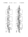
- FIG. 1 is a plan view onto a system for equipping component carriers with electrical components
- FIG. 2 is a plan view onto the system of FIG. 1 in a different setting
- FIG. 3 is a side view of a further system for equipping component carriers
- FIG. 4 is a further side view of a different system.
- a system for equipping component carriers 1 comprises three automatic equipping units 2 standing behind one another in a row, an equipping head thereat being movable over an equipping location to which the component carriers 1 can be transported.
- the system comprises two separate paths lying next to one another for transporting the component carriers 1 .
- One of the paths is designed a transport path 5 that leads over the equipping locations 4 lying in a line following one another.
- the other path is a pure conveying path 6 that is conducted past the equipping locations 4 immediately next to the transport path 5 .
- the two paths are subdivided into a plurality of independently drivable sections, whereby the sections lying in front of and behind the equipping location are designed as sub-transports 7 displaceable in the equipping plane transversely relative to the transport direction.
- a common carrier 8 that is displaceable transversely to the transport direction by the spacing of the two paths and that forms a handover unit.
- a component carrier that already resides in the preceding section can then be handed over onto the sub-transport by driving these two sections and can be transferred by retracting the carrier 8 with the two sub-transports into the transport path.
- such a component carrier can be handed over from the transport path 5 to the conveying path 6 , as indicated at the right-hand end of the transport path 5 .
- Such displacement events are possible at all sub-transports, so that the component carriers can be inserted into the transport path at an arbitrary location or, respectively, handed back over to the conveying path.
- the motion arrows illustrated in FIG. 1 show the corresponding displacement, drive and transport devices.
- the various component carriers 1 are already handed over here at the start of the transport path and pass through the individual equipping locations on a direct route, so that corresponding change procedures are omitted.
- the component carriers 1 are not processed in line, but parallel.
- the component carriers 1 are thereby completely equipped at only one respective equipping location 4 and are respectively transferred into the transport path 5 before the equipping location 4 and are in turn returned into the conveying path immediately thereafter.
- This mode is especially suitable for component carriers 1 that have to be equipped with a low number of components.
- the transport path 5 is not arranged next to but rather over the conveying path 6 . Accordingly, another carrier 9 for respectively two of the sub-transports 7 is displaceable in the vertical direction by the spacing between the two paths.
- the component carriers 1 can be transferred between the two paths in alternation, similar to the system according to FIGS. 1 and 2 .
- the free distance between the two paths is approximated here to the maximum height of the equipped component carrier 1 , so that the displacement paths are correspondingly short.
- the equipping location 4 is at the upper side of the paths, so that the equipping head 3 can place the components 10 onto the component carrier 1 unobstructed and with good accessibility.
- the conveying path 6 proceeds under the automatic equipping units 2 , whose foot parts 11 have been correspondingly raised.
- This has the advantage that the automatic equipping units 2 can remain unmodified.
- Two additional sub-transports 7 displaceable in height position are arranged between two respectively successive automatic equipping units and are combined to form a structural unit in a way that is not shown in detail. In the normal case, they align with the transport path 5 or, respectively, the conveying path 6 , as shown at the left side of the system.
- the lower sub-transport 7 is thereby displaceable between the conveying path 6 and the transport path 5 and can thus switch component carriers 1 between these paths.
- the upper sub-transport 7 is deflected up only to such an extent that enough space remains for the equipped component carrier 1 situated therebelow. These two sub-transports 7 can thus be displaced independently of one another.
Landscapes
- Engineering & Computer Science (AREA)
- Manufacturing & Machinery (AREA)
- Microelectronics & Electronic Packaging (AREA)
- Automatic Assembly (AREA)
- Supply And Installment Of Electrical Components (AREA)
Applications Claiming Priority (2)
| Application Number | Priority Date | Filing Date | Title |
|---|---|---|---|
| DE19821033 | 1998-05-11 | ||
| PCT/DE1999/001394 WO1999059389A2 (de) | 1998-05-11 | 1999-05-07 | Anlage zum bestücken von bauelementeträgern mit elektrischen bauelementen |
Publications (1)
| Publication Number | Publication Date |
|---|---|
| US7434675B1 true US7434675B1 (en) | 2008-10-14 |
Family
ID=7867384
Family Applications (1)
| Application Number | Title | Priority Date | Filing Date |
|---|---|---|---|
| US09/554,294 Expired - Fee Related US7434675B1 (en) | 1998-05-11 | 1999-05-07 | Facility for fitting component carriers with electric components |
Country Status (7)
| Country | Link |
|---|---|
| US (1) | US7434675B1 (ko) |
| EP (1) | EP1084600B1 (ko) |
| JP (1) | JP2002515655A (ko) |
| KR (1) | KR100604707B1 (ko) |
| CN (1) | CN1183817C (ko) |
| DE (1) | DE59909342D1 (ko) |
| WO (1) | WO1999059389A2 (ko) |
Cited By (12)
| Publication number | Priority date | Publication date | Assignee | Title |
|---|---|---|---|---|
| US20080251353A1 (en) * | 2007-04-11 | 2008-10-16 | Alpma Alpenland Maschinenbau Gmbh | Apparatus for the conveying of separated goods |
| US20090060696A1 (en) * | 2007-08-30 | 2009-03-05 | Mimaki Engineering Co., Ltd. | Printing apparatus |
| US20090056569A1 (en) * | 2007-08-30 | 2009-03-05 | Mimaki Engineering Co., Ltd. | Printing apparatus |
| US20090277754A1 (en) * | 2008-05-09 | 2009-11-12 | Caterpillar Inc. | Modular manufacturing chain including a vertical lift device and method of operation thereof |
| US20100122636A1 (en) * | 2008-11-19 | 2010-05-20 | Illinois Tool Works Inc. | Vertically separated pass through conveyor system and method in surface mount technology process equipment |
| US20100133064A1 (en) * | 2008-12-02 | 2010-06-03 | Fuji Machine Mfg. Co., Ltd. | Circuit board inspection apparatus |
| US20100204827A1 (en) * | 2006-03-22 | 2010-08-12 | Datacard Corporation | Linear machine for processing portable objects and method for processing portable objects |
| US20120159900A1 (en) * | 2010-12-22 | 2012-06-28 | Giorgio Grasselli | Apparatus for laying sliced foods into containers |
| US20140271056A1 (en) * | 2013-03-15 | 2014-09-18 | Wistron Corporation | Unloading system for unloading a circuit board automatically |
| US20170266950A1 (en) * | 2016-03-16 | 2017-09-21 | Taotech Digital Technology Co., Ltd | Circulating feeding printer combining screen printing and digital ink jetting |
| US10766714B2 (en) * | 2017-06-22 | 2020-09-08 | Itoh Denki Co., Ltd. | Lifting device and sporting device |
| US11351639B2 (en) * | 2018-03-29 | 2022-06-07 | Hirata Corporation | Working system and work method |
Families Citing this family (10)
| Publication number | Priority date | Publication date | Assignee | Title |
|---|---|---|---|---|
| CN1248563C (zh) | 1999-12-16 | 2006-03-29 | 西门子公司 | 装配基板的装配设备和带有所述装配设备的装配线 |
| US6836960B2 (en) | 2000-05-15 | 2005-01-04 | Matsushita Electric Industrial Co., Ltd. | Board transfer apparatus, board transfer method, and component mounting apparatus |
| DE10225430A1 (de) * | 2002-06-07 | 2003-12-24 | Siemens Ag | Bestücksystem und Verfahren zum Bestücken von Substraten mit Bauelementen |
| JP4342185B2 (ja) * | 2003-01-15 | 2009-10-14 | 富士機械製造株式会社 | 実装ラインにおける基板搬入方法および基板生産システム |
| JP3960278B2 (ja) * | 2003-08-13 | 2007-08-15 | ヤマハ株式会社 | 接続設定プログラム |
| DE102007017258B4 (de) * | 2007-04-12 | 2013-05-16 | Asm Assembly Systems Gmbh & Co. Kg | Zuführung von Flächenmagazinen mittels einer Transportstrecke eines Leiterplatten-Transportsystems mit mehreren Transportstrecken |
| DE112008002687A5 (de) * | 2007-10-09 | 2010-11-04 | Siemens Electronics Assembly Systems Gmbh & Co. Kg | Zuführvorrichtung für Bauelemente zu einem Bestückautomaten zur Bestückung von Substraten mit den Bauelementen |
| JP2010050398A (ja) * | 2008-08-25 | 2010-03-04 | Juki Corp | 表面実装装置 |
| JP4992871B2 (ja) * | 2008-09-04 | 2012-08-08 | パナソニック株式会社 | 電子部品実装システム |
| DE102010013506A1 (de) * | 2010-03-31 | 2011-10-06 | Mimot Gmbh | Vorrichtung zum Bearbeiten von Werkstücken |
Citations (12)
| Publication number | Priority date | Publication date | Assignee | Title |
|---|---|---|---|---|
| US4658947A (en) * | 1984-11-08 | 1987-04-21 | Raymond Production Systems | Transfer mechanism |
| DE3601699A1 (de) | 1986-01-22 | 1987-07-23 | Bosch Gmbh Robert | Foerdereinrichtung zum transport von werkstuecken |
| US4783904A (en) | 1987-11-20 | 1988-11-15 | Sony Corporation | Automatic assembly apparatus |
| US4867299A (en) * | 1987-07-16 | 1989-09-19 | Meinan Machinery Works, Inc. | Apparatus for distributing veneer sheets |
| US4999578A (en) * | 1988-01-20 | 1991-03-12 | Nec Home Electronics Ltd. | Function inspecting system |
| US5078257A (en) * | 1989-11-21 | 1992-01-07 | Donald W. Carter, Jr. | Lattice production line and method of operating such a line |
| JPH04176528A (ja) | 1990-11-07 | 1992-06-24 | Matsushita Electric Ind Co Ltd | 搬送装置を有する生産装置 |
| US5145052A (en) * | 1991-04-10 | 1992-09-08 | Axis Usa, Inc. | Apparatus for substantially simultaneously processing multiple electric motor parts |
| JPH06144556A (ja) | 1992-11-05 | 1994-05-24 | Pioneer Electron Corp | パラレルインラインコンベア装置 |
| US5372239A (en) | 1992-05-19 | 1994-12-13 | Kabushiki Kaisha Shinkawa | Apparatus for conveying plate-form articles |
| DE19521729A1 (de) | 1994-06-15 | 1995-12-21 | Universal Instruments Corp | Verfahren zur Herstellung von Platinen durch mehrspurige Beförderungshandhabung von Platinen |
| US6220420B1 (en) * | 1999-03-30 | 2001-04-24 | Industrial Technology Research Institute | Semiconductor composition material conveyer module |
-
1999
- 1999-05-07 JP JP2000549077A patent/JP2002515655A/ja active Pending
- 1999-05-07 WO PCT/DE1999/001394 patent/WO1999059389A2/de active IP Right Grant
- 1999-05-07 EP EP99932665A patent/EP1084600B1/de not_active Expired - Lifetime
- 1999-05-07 KR KR1020007012539A patent/KR100604707B1/ko not_active IP Right Cessation
- 1999-05-07 CN CNB998038431A patent/CN1183817C/zh not_active Expired - Fee Related
- 1999-05-07 US US09/554,294 patent/US7434675B1/en not_active Expired - Fee Related
- 1999-05-07 DE DE59909342T patent/DE59909342D1/de not_active Expired - Lifetime
Patent Citations (12)
| Publication number | Priority date | Publication date | Assignee | Title |
|---|---|---|---|---|
| US4658947A (en) * | 1984-11-08 | 1987-04-21 | Raymond Production Systems | Transfer mechanism |
| DE3601699A1 (de) | 1986-01-22 | 1987-07-23 | Bosch Gmbh Robert | Foerdereinrichtung zum transport von werkstuecken |
| US4867299A (en) * | 1987-07-16 | 1989-09-19 | Meinan Machinery Works, Inc. | Apparatus for distributing veneer sheets |
| US4783904A (en) | 1987-11-20 | 1988-11-15 | Sony Corporation | Automatic assembly apparatus |
| US4999578A (en) * | 1988-01-20 | 1991-03-12 | Nec Home Electronics Ltd. | Function inspecting system |
| US5078257A (en) * | 1989-11-21 | 1992-01-07 | Donald W. Carter, Jr. | Lattice production line and method of operating such a line |
| JPH04176528A (ja) | 1990-11-07 | 1992-06-24 | Matsushita Electric Ind Co Ltd | 搬送装置を有する生産装置 |
| US5145052A (en) * | 1991-04-10 | 1992-09-08 | Axis Usa, Inc. | Apparatus for substantially simultaneously processing multiple electric motor parts |
| US5372239A (en) | 1992-05-19 | 1994-12-13 | Kabushiki Kaisha Shinkawa | Apparatus for conveying plate-form articles |
| JPH06144556A (ja) | 1992-11-05 | 1994-05-24 | Pioneer Electron Corp | パラレルインラインコンベア装置 |
| DE19521729A1 (de) | 1994-06-15 | 1995-12-21 | Universal Instruments Corp | Verfahren zur Herstellung von Platinen durch mehrspurige Beförderungshandhabung von Platinen |
| US6220420B1 (en) * | 1999-03-30 | 2001-04-24 | Industrial Technology Research Institute | Semiconductor composition material conveyer module |
Non-Patent Citations (1)
| Title |
|---|
| German translation of Japanese Office Action dated Apr. 17, 2008 in corresponding Japanese Application No. 2000-549077. |
Cited By (36)
| Publication number | Priority date | Publication date | Assignee | Title |
|---|---|---|---|---|
| US20100204827A1 (en) * | 2006-03-22 | 2010-08-12 | Datacard Corporation | Linear machine for processing portable objects and method for processing portable objects |
| US7975827B2 (en) * | 2006-03-22 | 2011-07-12 | Datacard Corporation | Linear machine for processing portable objects and method for processing portable objects |
| US7717251B2 (en) * | 2007-04-11 | 2010-05-18 | Alpma Alpenland Maschinenbau Gmbh | Apparatus for the conveying of separated goods |
| US20080251353A1 (en) * | 2007-04-11 | 2008-10-16 | Alpma Alpenland Maschinenbau Gmbh | Apparatus for the conveying of separated goods |
| US20090060696A1 (en) * | 2007-08-30 | 2009-03-05 | Mimaki Engineering Co., Ltd. | Printing apparatus |
| US20090056569A1 (en) * | 2007-08-30 | 2009-03-05 | Mimaki Engineering Co., Ltd. | Printing apparatus |
| US8528717B2 (en) * | 2007-08-30 | 2013-09-10 | Mimaki Engineering Co., Ltd. | Printing apparatus |
| US8205736B2 (en) * | 2007-08-30 | 2012-06-26 | Mimaki Engineering Co., Ltd. | Printing apparatus |
| US20090277754A1 (en) * | 2008-05-09 | 2009-11-12 | Caterpillar Inc. | Modular manufacturing chain including a vertical lift device and method of operation thereof |
| US7900767B2 (en) * | 2008-05-09 | 2011-03-08 | Caterpillar Inc. | Modular manufacturing chain including a vertical lift device and method of operation thereof |
| US8413578B2 (en) | 2008-11-19 | 2013-04-09 | Illinois Tool Works Inc. | Modular printing system having vertically separated pass through conveyor system |
| US8413577B2 (en) | 2008-11-19 | 2013-04-09 | Illinois Tool Works Inc. | Vertically separated pass through conveyor system and method in surface mount technology process equipment |
| US8939076B2 (en) | 2008-11-19 | 2015-01-27 | Illinois Tool Works Inc. | Vertically separated pass through conveyor system and method in surface mount technology process equipment |
| US20100122635A1 (en) * | 2008-11-19 | 2010-05-20 | Illinois Tool Works Inc. | Vertically separated pass through conveyor system and method in surface mount technology process equipment |
| US20100125359A1 (en) * | 2008-11-19 | 2010-05-20 | Illinois Tool Works Inc. | Vertically separated pass through conveyor system and method in surface mount technology process equipment |
| US20100122634A1 (en) * | 2008-11-19 | 2010-05-20 | Illinois Tool Works Inc. | Vertically separated pass through conveyor system and method in surface mount technology process equipment |
| US20100122633A1 (en) * | 2008-11-19 | 2010-05-20 | Illinois Tool Works Inc. | Vertically separated pass through conveyor system and method in surface mount technology process equipment |
| WO2010059486A1 (en) * | 2008-11-19 | 2010-05-27 | Illinois Tool Works Inc. | Vertically separated pass through conveyor system and method in surface mount technology process equipment |
| US20100125357A1 (en) * | 2008-11-19 | 2010-05-20 | Illinois Tool Works Inc. | Vertically separated pass through conveyor system and method in surface mount technology process equipment |
| US9345147B2 (en) | 2008-11-19 | 2016-05-17 | Illinois Tool Works, Inc. | Vertically separated pass through conveyor system and method in surface mount technology process equipment |
| US20100122636A1 (en) * | 2008-11-19 | 2010-05-20 | Illinois Tool Works Inc. | Vertically separated pass through conveyor system and method in surface mount technology process equipment |
| US8555783B2 (en) | 2008-11-19 | 2013-10-15 | Illinois Tool Works Inc. | Apparatus for depositing viscous material including transport system with upper and lower tracks |
| US8555784B2 (en) | 2008-11-19 | 2013-10-15 | Illinois Tool Works Inc. | Method of processing electronic substrates using vertically separated pass through conveyor system |
| US8613134B2 (en) | 2008-11-19 | 2013-12-24 | Illinois Tool Works Inc. | Method of conveying printed circuit boards |
| CN104302161A (zh) * | 2008-11-19 | 2015-01-21 | 伊利诺斯工具制品有限公司 | 在表面安装技术处理设备中的垂直分开的穿过传送系统和方法 |
| CN104302161B (zh) * | 2008-11-19 | 2018-02-09 | 伊利诺斯工具制品有限公司 | 在表面安装技术处理设备中的垂直分开的穿过传送系统和方法 |
| US8651262B2 (en) * | 2008-12-02 | 2014-02-18 | Fuji Machine Mfg. Co., Ltd. | Circuit board inspection apparatus |
| US20100133064A1 (en) * | 2008-12-02 | 2010-06-03 | Fuji Machine Mfg. Co., Ltd. | Circuit board inspection apparatus |
| US20120159900A1 (en) * | 2010-12-22 | 2012-06-28 | Giorgio Grasselli | Apparatus for laying sliced foods into containers |
| US9102428B2 (en) * | 2010-12-22 | 2015-08-11 | Giorgio Grasselli | Apparatus for laying sliced foods into containers |
| US9095086B2 (en) * | 2013-03-15 | 2015-07-28 | Wistron Corporation | Unloading system for unloading a circuit board automatically |
| US20140271056A1 (en) * | 2013-03-15 | 2014-09-18 | Wistron Corporation | Unloading system for unloading a circuit board automatically |
| US20170266950A1 (en) * | 2016-03-16 | 2017-09-21 | Taotech Digital Technology Co., Ltd | Circulating feeding printer combining screen printing and digital ink jetting |
| US9919513B2 (en) * | 2016-03-16 | 2018-03-20 | Taotech Digital Technology Co., Ltd. | Circulating feeding printer combining screen printing and digital ink jetting |
| US10766714B2 (en) * | 2017-06-22 | 2020-09-08 | Itoh Denki Co., Ltd. | Lifting device and sporting device |
| US11351639B2 (en) * | 2018-03-29 | 2022-06-07 | Hirata Corporation | Working system and work method |
Also Published As
| Publication number | Publication date |
|---|---|
| CN1300530A (zh) | 2001-06-20 |
| KR20010043476A (ko) | 2001-05-25 |
| WO1999059389A2 (de) | 1999-11-18 |
| EP1084600B1 (de) | 2004-04-28 |
| EP1084600A2 (de) | 2001-03-21 |
| JP2002515655A (ja) | 2002-05-28 |
| DE59909342D1 (de) | 2004-06-03 |
| WO1999059389A3 (de) | 2000-01-20 |
| KR100604707B1 (ko) | 2006-07-28 |
| CN1183817C (zh) | 2005-01-05 |
Similar Documents
| Publication | Publication Date | Title |
|---|---|---|
| US7434675B1 (en) | Facility for fitting component carriers with electric components | |
| US5884746A (en) | Modular assembly line system | |
| US5517748A (en) | Apparatus for conveying circuit boards through a component-mounting station | |
| US6591961B2 (en) | Carrying system | |
| EP0633208A1 (en) | Article sorting method and system | |
| KR20010108045A (ko) | 컨베이어 장치 | |
| CN112074470B (zh) | 拣选系统 | |
| CN101282636B (zh) | 对基板作业系统 | |
| CN100508721C (zh) | 对基板作业系统 | |
| EP2331379B1 (en) | Ropeway system, method of operating such a system, and ropeway system switching device | |
| US5729892A (en) | Component feeding system | |
| CN210854353U (zh) | 一种集中供料设备 | |
| US20030226251A1 (en) | Fitting system and method of fitting substrates with components | |
| KR100259148B1 (ko) | 순환식 부품 공급 장치 | |
| GB2316416A (en) | Apparatus for conveying sliver cans | |
| JP2695781B2 (ja) | 荷の並べ換え装置 | |
| KR20030018075A (ko) | 부품 장착 장치를 작동시키기 위한 방법, 상기 방법을실시하기 위한 부품 장착 장치 및 상기 부품 장착 장치를위한 이송 장치 | |
| GB2223213A (en) | Segmented rail assembly for closed loop work station conveyor system. | |
| EP0507413B1 (en) | Distributing conveyor | |
| US6398005B1 (en) | Conveyance system with skid handling | |
| US7975827B2 (en) | Linear machine for processing portable objects and method for processing portable objects | |
| US20110240438A1 (en) | Arrangement for working workpieces | |
| CN215624490U (zh) | 天轨机构及货物拣选系统 | |
| CN115489916A (zh) | 车辆存储仓库 | |
| WO2022138049A1 (ja) | 物品収容設備(article storage facility) |
Legal Events
| Date | Code | Title | Description |
|---|---|---|---|
| STCF | Information on status: patent grant |
Free format text: PATENTED CASE |
|
| AS | Assignment |
Owner name: SIEMENS ELECTRONICS ASSEMBLY SYSTEMS GMBH &CO. KG, Free format text: ASSIGNMENT OF ASSIGNORS INTEREST;ASSIGNOR:SIEMENS AKTIENGESELLSCHAFT;REEL/FRAME:022928/0316 Effective date: 20090707 |
|
| FEPP | Fee payment procedure |
Free format text: PAYOR NUMBER ASSIGNED (ORIGINAL EVENT CODE: ASPN); ENTITY STATUS OF PATENT OWNER: LARGE ENTITY |
|
| AS | Assignment |
Owner name: ASM ASSEMBLY SYSTEMS GMBH & CO. KG, GERMANY Free format text: CHANGE OF NAME;ASSIGNOR:SIEMENS ELECTRONICS ASSEMBLY SYSTEMS GMBH & CO. KG;REEL/FRAME:025919/0452 Effective date: 20110112 |
|
| FPAY | Fee payment |
Year of fee payment: 4 |
|
| FPAY | Fee payment |
Year of fee payment: 8 |
|
| FEPP | Fee payment procedure |
Free format text: MAINTENANCE FEE REMINDER MAILED (ORIGINAL EVENT CODE: REM.); ENTITY STATUS OF PATENT OWNER: LARGE ENTITY |
|
| LAPS | Lapse for failure to pay maintenance fees |
Free format text: PATENT EXPIRED FOR FAILURE TO PAY MAINTENANCE FEES (ORIGINAL EVENT CODE: EXP.); ENTITY STATUS OF PATENT OWNER: LARGE ENTITY |
|
| STCH | Information on status: patent discontinuation |
Free format text: PATENT EXPIRED DUE TO NONPAYMENT OF MAINTENANCE FEES UNDER 37 CFR 1.362 |
|
| FP | Lapsed due to failure to pay maintenance fee |
Effective date: 20201014 |