US7077395B2 - Sheet after-treatment device and image forming apparatus equipped with the device - Google Patents
Sheet after-treatment device and image forming apparatus equipped with the device Download PDFInfo
- Publication number
- US7077395B2 US7077395B2 US10/429,786 US42978603A US7077395B2 US 7077395 B2 US7077395 B2 US 7077395B2 US 42978603 A US42978603 A US 42978603A US 7077395 B2 US7077395 B2 US 7077395B2
- Authority
- US
- United States
- Prior art keywords
- sheet
- treatment device
- stapler
- lower jaw
- guide
- Prior art date
- Legal status (The legal status is an assumption and is not a legal conclusion. Google has not performed a legal analysis and makes no representation as to the accuracy of the status listed.)
- Expired - Lifetime, expires
Links
- 238000011144 upstream manufacturing Methods 0.000 claims description 39
- 238000007599 discharging Methods 0.000 claims description 8
- 230000003247 decreasing effect Effects 0.000 claims 2
- 238000010276 construction Methods 0.000 description 9
- 238000010586 diagram Methods 0.000 description 6
- 230000009467 reduction Effects 0.000 description 6
- 230000008901 benefit Effects 0.000 description 4
- 239000000123 paper Substances 0.000 description 4
- 238000011084 recovery Methods 0.000 description 4
- 230000015572 biosynthetic process Effects 0.000 description 3
- 230000000694 effects Effects 0.000 description 2
- 238000000034 method Methods 0.000 description 2
- 230000008569 process Effects 0.000 description 2
- 239000011347 resin Substances 0.000 description 2
- 229920005989 resin Polymers 0.000 description 2
- 230000000717 retained effect Effects 0.000 description 2
- 230000009471 action Effects 0.000 description 1
- 238000006073 displacement reaction Methods 0.000 description 1
- 230000006872 improvement Effects 0.000 description 1
- 230000007257 malfunction Effects 0.000 description 1
Images


Classifications
-
- G—PHYSICS
- G03—PHOTOGRAPHY; CINEMATOGRAPHY; ANALOGOUS TECHNIQUES USING WAVES OTHER THAN OPTICAL WAVES; ELECTROGRAPHY; HOLOGRAPHY
- G03G—ELECTROGRAPHY; ELECTROPHOTOGRAPHY; MAGNETOGRAPHY
- G03G15/00—Apparatus for electrographic processes using a charge pattern
-
- B—PERFORMING OPERATIONS; TRANSPORTING
- B27—WORKING OR PRESERVING WOOD OR SIMILAR MATERIAL; NAILING OR STAPLING MACHINES IN GENERAL
- B27F—DOVETAILED WORK; TENONS; SLOTTING MACHINES FOR WOOD OR SIMILAR MATERIAL; NAILING OR STAPLING MACHINES
- B27F7/00—Nailing or stapling; Nailed or stapled work
- B27F7/17—Stapling machines
- B27F7/19—Stapling machines with provision for bending the ends of the staples on to the work
-
- B—PERFORMING OPERATIONS; TRANSPORTING
- B42—BOOKBINDING; ALBUMS; FILES; SPECIAL PRINTED MATTER
- B42C—BOOKBINDING
- B42C1/00—Collating or gathering sheets combined with processes for permanently attaching together sheets or signatures or for interposing inserts
- B42C1/12—Machines for both collating or gathering and permanently attaching together the sheets or signatures
-
- B—PERFORMING OPERATIONS; TRANSPORTING
- B65—CONVEYING; PACKING; STORING; HANDLING THIN OR FILAMENTARY MATERIAL
- B65H—HANDLING THIN OR FILAMENTARY MATERIAL, e.g. SHEETS, WEBS, CABLES
- B65H29/00—Delivering or advancing articles from machines; Advancing articles to or into piles
- B65H29/52—Stationary guides or smoothers
-
- B—PERFORMING OPERATIONS; TRANSPORTING
- B65—CONVEYING; PACKING; STORING; HANDLING THIN OR FILAMENTARY MATERIAL
- B65H—HANDLING THIN OR FILAMENTARY MATERIAL, e.g. SHEETS, WEBS, CABLES
- B65H2408/00—Specific machines
- B65H2408/10—Specific machines for handling sheet(s)
- B65H2408/12—Specific machines for handling sheet(s) stapler arrangement
-
- B—PERFORMING OPERATIONS; TRANSPORTING
- B65—CONVEYING; PACKING; STORING; HANDLING THIN OR FILAMENTARY MATERIAL
- B65H—HANDLING THIN OR FILAMENTARY MATERIAL, e.g. SHEETS, WEBS, CABLES
- B65H2701/00—Handled material; Storage means
- B65H2701/10—Handled articles or webs
- B65H2701/17—Nature of material
- B65H2701/176—Cardboard
Definitions
- the present invention relates to a sheet after-treatment device for performing after-treatment on sheets and to an image forming apparatus equipped with the sheet after-treatment device as a component.
- the present invention relates to a sheet after-treatment device allowing a reduction in size without impairing sheet transport and to an image forming apparatus equipped with such a device.
- a sheet after-treatment device is provided, for example, in the main body of an image forming apparatus as one of the components of the image forming apparatus, to perform after-treatment on a sheet with an image formed thereon transported from the apparatus main body.
- the image forming apparatus which forms an image on a sheet, may consist of a copying machine, a printer, a facsimile apparatus, or a multifunction apparatus consisting of a combination of such apparatuses.
- the sheet, on which an image is to be formed may consist of an ordinary paper sheet, a thin sheet of resin which is an ordinary paper substitute, a cardboard, a postcard, a sealed letter, a sheet for an overhead projector or the like.
- a sheet after-treatment device provided in the main body of an image forming apparatus aligns the end portions of a plurality of sheets which have undergone image formation (printing) and performs an after-treatment such as stapling.
- FIG. 10 shows an example of the construction of a sheet after-treatment device.
- This sheet after-treatment device designated by a numeral reference 1000 , is equipped with a discharge roller pair 1003 constituting a sheet discharge outlet, an intermediate stacking surface 1002 on which the discharged sheets are stacked together, a stapler 1001 arranged on the opposite side with respect to the sheet transport direction indicated by the arrow E, etc.
- the sheets discharged from the discharge roller pair 1003 are stacked on the intermediate stacking surface 1002 , and undergo switch-back transport in the direction indicated by the arrow F toward an opening 1001 a of the stapler 1001 .
- the sheets are introduced into the opening 1001 a .
- the stack of sheets SB is stapled by the stapler 1001 before being discharged to the left as seen in FIG. 10 .
- FIGS. 11A through 11C show another example of the construction of a sheet after-treatment device.
- a stapler 1011 is arranged off the sheet transport path so that it may not obstruct the transport of sheets in the direction indicated by the arrow Q.
- the sheet after-treatment device 1000 In the former type of conventional sheet after-treatment device 1000 , shown in FIG. 10 , in which the sheets, once transported in the direction of the arrow E, are transported backwards in the direction of the arrow F, it is necessary for the intermediate stacking surface 1002 and the stapler 1001 to be arranged at a position one step lower than the discharge roller pair 1003 . Accordingly, the sheet after-treatment device 1000 requires extra space in the vertical direction, which leads to a rather large height, resulting in a rather large device size.
- ineffective staples generated as a result of mis-stapling or the like of the staplers 1001 and 1011 can fall to cause short-circuiting in the electrical components.
- the provision of the recovery tray requires extra space, resulting in an increase in the general size of the device and in cost.
- Another object of the present invention is to provide a sheet after-treatment device capable of recovering ineffective staples without involving any substantial increase in space.
- Still another object of the present invention is to provide an image forming apparatus whose main body is equipped with a sheet after-treatment device as mentioned above.
- a sheet after-treatment device including: stapling means for stapling sheets fed between upper and lower jaws in an opened state with a staple by closing the upper and lower jaws; and holding means for holding the stapling means, in which an upper end of an upstream-side portion of the holding means and the lower jaw of the stapling means are arranged in an area where the sheets are transported, and the upper end of the upstream-side portion of the holding means is situated above the lower jaw.
- sheet alignment means for aligning the sheet ends in a direction intersecting the sheet transport direction to effect positioning of the sheets at a sheet stapling position.
- the staple is projected from the lower jaw, which is stationary, and the upper jaw moves toward and away from the lower jaw to bend the staple.
- a sheet guide portion for guiding sheets on the upstream side of the holding means, and the sheet guide portion, the upstream-side portion of the holding means, and the lower jaw are arranged such that the following are ranked in height as follows in descending order: the sheet guide portion, the upper end of the upstream-side portion of the holding means, and the lower jaw.
- a sheet guide portion for guiding sheets on the upstream side of the holding means, and the sheet guide portion, the upstream-side portion of the holding means, the lower jaw, and the downstream-side portion of the holding means are arranged such that the following are ranked in height as follows in descending order: the sheet guide portion, the upper end of the upstream side portion of the holding means, the lower jaw, and the upper end of the downstream-side portion of the holding means.
- the upper end of the upstream-side portion of the holding means constitutes a guide surface for guiding the sheets that are fed.
- a region formed by an upstream-side portion of the holding means and the upper surface of the lower jaw constitutes a staple storage portion for storing staples resulting from mis-stapling of the sheets.
- a gap for accommodating ineffective staples generated as a result of mis-stapling of sheets is provided at least between the stapling means and the upstream side of the holding means.
- the sheet after-treatment device of the present invention there is further provided on the upstream side of the holding means a gap for accommodating staples resulting from mis-stapling of the sheets.
- the gap has an inclined staple guide surface for guiding staples resulting from mis-stapling of the sheets.
- the stapling means and the holding means are inclined such that they are lower on the upstream side with respect to the sheet transport direction.
- the stapling means and the holding means are provided so as to be capable of displacement so that the opening of the upper and lower jaws may be exposed.
- the stapling means and the holding means are provided so as to be rotatable from the downstream side to the upstream side with respect to the sheet transport direction so that the opening of the upper and lower jaws may be exposed.
- an image forming apparatus including: image forming means for forming images on sheets; and a sheet after-treatment device for stapling the sheets with the images formed thereon, in which the sheet after-treatment device is one as described above.
- the opening of the stapler unit 208 in the sheet transport area, thereby making it possible to achieve a reduction in size and cost.
- the image forming apparatus of the present invention which is equipped with a sheet after-treatment device allowing a reduction in size and cost, can be produced in a small size and at low cost.
- the image forming apparatus of the present invention which is equipped with the above-described sheet after-treatment device capable of avoiding the danger of short-circuiting in the electrical components, it is possible to prevent damage to the device.
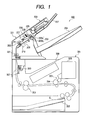
- FIG. 1 is a sectional view of a printer constituting an image forming apparatus having a sheet after-treatment device according to a first embodiment of the present invention in the upper portion of the apparatus main body as one of the components thereof;
- FIG. 2 is a schematic sectional view showing the general construction of the sheet after-treatment device of the first embodiment of the present invention
- FIG. 3A is an exploded view of a stapler unit according to the first embodiment of the present invention.
- FIG. 3B is a right-hand side view of the stapler unit of FIG. 3A ;
- FIG. 4A is a diagram showing the stapler unit of the first embodiment of the present invention, in which a stapler main body and a holder are formed into an integral unit, as seen from the upstream side with respect to the sheet transport direction;
- FIG. 4B is a right-hand side view of the stapler unit of FIG. 4A ;
- FIGS. 5A , 5 B, 5 C and 5 D are diagrams showing the positional relationship between the transport area for the sheet being transported and the stapler unit in the sheet after-treatment device of the first embodiment of the present invention, of which:
- FIG. 6 is a schematic sectional view showing the general construction of the sheet after-treatment device according to a second embodiment of the present invention.
- FIG. 7A is a front view of a stapler unit in a sheet after-treatment device according to a third embodiment of the present invention.
- FIG. 7B is a sectional view taken along the line VIIB—VIIB of FIG. 7A ;
- FIG. 8 is a perspective view of the stapler unit of the first embodiment of the present invention.
- FIG. 9 is a diagram showing the stapler unit of FIG. 8 as rotated until the opening of the stapler main body is exposed;
- FIG. 10 is a schematic diagram showing a conventional sheet after-treatment device
- FIGS. 11A , 11 B and 11 C are schematic plan views of another conventional sheet after-treatment device, of which:
- the sheet after-treatment device is provided, for example, in the main body of an image forming apparatus as a component of the image forming apparatus, and is adapted to perform after-treatment on a sheet with an image formed thereon transported from the apparatus main body.
- the image forming apparatus may consist of a copying machine, a printer, a facsimile apparatus, or a multifunction apparatus formed by combining these apparatuses.
- the sheet after-treatment device of this embodiment is provided, in a printer, typically a laser beam printer, as a component thereof. However, this should not be construed restrictively. It may also be provided in an apparatus other than a printer.
- the sheet, on which an image is to be formed may consist of an ordinary paper sheet, a thin sheet of resin which is an ordinary paper substitute, a cardboard, a postcard, a sealed letter, a sheet for an overhead projector or the like.
- FIG. 1 shows a printer 300 , whose main body 301 has in the upper portion thereof a sheet after-treatment device 200 according to the first embodiment as one of the components of the printer 300 .
- the printer may also be equipped with a sheet after-treatment device according to another embodiment.
- the printer 300 its main body 301 is connected by itself to a computer or a network such as LAN, and, on the basis of image information, print signals etc. supplied from the computer, network or the like, an image is formed (printed) on a sheet by a predetermined image formation process before discharging the sheet.
- This printer 300 may also be equipped with a reading portion for reading originals, in which case an image of an original is copied on a sheet on the basis of reading information supplied from the reading portion before the sheet is discharged.
- the printer main body 301 and the sheet after-treatment device 200 are electrically connected to each other by a cable connector (not shown).
- a plurality of sheets S are stacked in a feeding cassette 302 provided in the lower portion of the printer main body 301 .
- the plurality of sheets S are fed one by one, starting with the uppermost one, to an image forming portion 303 constituting the image forming means.
- an toner image is formed by a so-called laser beam image forming process on the basis of predetermined print signals supplied from the computer, network or the like, and the toner image thus formed is transferred to the upper surface of a sheet S fed from the feeding cassette 302 .
- the toner image has already been formed on a photosensitive drum 304 of the image forming portion 303 using toner in a cartridge 305 .
- the sheet S to which the image has been fixed is discharged either to a face-down discharge portion 308 provided in the upper portion of the printer main body 301 or to a stacking tray 204 of the sheet after-treatment device 200 according to the position of a flapper 307 of the printer 301 , which is switched based on a control signal from a control portion (not shown).
- the sheet is guided by the flapper 307 switched to the position indicated by the broken line.
- the sheet is turned back in a substantially U-shaped sheet transport path leading to a discharge roller pair 309 .
- the image surface is reversed, and the sheet is discharged face down from the printer main body 301 to the face-down discharge portion 308 by the discharge roller pair 309 , with the toner image facing down.
- the sheet after-treatment device 200 receives the sheet discharged to the exterior from the printer main body 301 , and treats the sheet in a simple stacking mode or an after-treatment mode.
- the sheet after-treatment device 200 When the simple stacking mode is selected for the sheet after-treatment device 200 , the sheet is transported by an inlet roller pair 201 , an intermediate roller pair 202 , and a discharge roller pair 203 and placed on a stacking tray 204 .
- upper and lower rollers 203 a and 203 b of the discharge roller pair 203 are spaced apart from each other, and a plurality of sheets are passed over a stopper 310 by the inlet roller pair 201 and the intermediate roller pair 202 and temporarily stacked on an intermediate stacking portion 205 .
- the sheet after-treatment device 200 causes a transport direction alignment paddle 206 to rotate clockwise from the position as shown in FIG. 1 to reversely transport the sheet stack on the intermediate stacking portion 205 until it abuts a stopper 310 for end regulation in the sheet transport direction.
- a sheet alignment means for example, a lateral alignment means 207 .
- the sheet after-treatment device 200 performs stapling by means of a stapler unit H 1 , and the rollers of the discharge roller pair 203 are brought into press contact with each other again to discharge the sheet stack onto the stacking tray 204 .
- the paddle 206 rotates around a shaft 227 , which is equipped with a lever 228 at the forward end of which the upper roller 203 a is rotatably provided.
- the lever 228 is urged by a spring 229 to keep the upper roller 203 a in press contact with the lower roller 203 b.
- FIGS. 3A and 3B are exploded views showing the construction of the stapler unit H 1 .
- the stapler unit H 1 is equipped with a stapler main body 208 , box-like holders 211 and 212 , a staple cartridge C, etc.
- the stapler main body 208 is equipped with upper and lower jaws 209 and 210 . When the upper and lower jaws 209 and 210 gape, an opening 220 is defined.
- a staple is projected from the stationary lower jaw 210 to penetrate the sheets introduced into the opening 220 , and, at the same time, the upper jaw 209 is moved downwards to bend the staple, thereby stapling the sheet stack.
- the holders 211 and 212 hold the stapler main body 208 from above and below to fix it to the main body 221 of the sheet after-treatment device 200 .
- the staple cartridge C is detachable with respect to the stapler main body 208 and contains staples (not shown).
- FIGS. 4A and 4B show the stapler unit H 1 as formed by assembling the stapler main body 208 and the holders 211 and 212 .
- Sheet transport guide surfaces 213 and 214 are formed integrally with the holders 211 and 212 .
- the sheet transport guide surfaces 213 and 214 serve to guide the entering sheets S to the opening 220 of the stapler main body 208 .
- FIG. 2 is a schematic diagram showing the construction of the stapler unit H 1 and the periphery thereof.
- the stapler main body 208 held by the holders 211 and 212 , is arranged so as to be inclined to the sheet-transport upstream side by an angle ⁇ with respect to the vertical direction. That is, the stapler unit H 1 is inclined such that it is lower on the upstream side with respect to the sheet transport direction.
- a pocket portion 215 serving as a staple storage portion.
- This pocket portion 215 accommodates ineffective staples resulting from mis-stapling of sheets. Since the stapler unit H 1 is inclined so as to be lower on the upstream side with respect to the sheet transport direction, the ineffective staples in the pocket portion 215 are gathered on one side, thus making it possible to remove the ineffective staples. Note that even if the stapler unit H 1 is not inclined so as to be lower on the upstream side with respect to the sheet transport direction, it is possible to store ineffective staples in the pocket portion 215 . By storing the ineffective staples in the pocket portion 215 , it is possible to eliminate the danger of ineffective staples falling to cause short-circuiting in the electrical components.
- FIGS. 5A , 5 B, 5 C, and 5 D are plan views showing the positional relationship between the transport area SA for the sheet S being transported and the stapler unit H 1 .
- the opening 220 of the stapler unit H 1 overlaps the transport area SA for the sheet S. That is, the sheet transport guide surface 214 at the upper end of the side wall 212 a of the holder 212 on the sheet entrance side (See FIG. 2 ) and the upper surface 210 a of the lower jaw 210 are situated in the sheet transport area SA.
- the sheet S transported in the sheet transport area SA in the direction of the arrow M as shown in FIG. 5A passes the opening 220 of the stapler main body 208 , and is placed on the intermediate stacking portion 205 , as shown in FIG. 5 B. Thereafter, as shown in FIG. 5C , the sheet is transported reversely in the direction of the arrow N by the transport direction alignment paddle 206 to abut a transport stopper 310 (See FIG. 1 ). These operations are conducted each time a transported sheet arrives.
- the sheet passes the sheet transport guide surface 214 to abut the stopper 310 . Since the intermediate stacking portion 205 is substantially flush with the sheet transport guide surface 214 , there is no fear of the sheet being caught by the sheet transport guide surface 214 . The sheets following the first one are transported reversely in the direction of the arrow N over the first sheet, so that there is no fear of these sheets being caught by the sheet transport guide surface 214 .
- the resultant sheet stack SB is moved in the direction of the arrow R to the sheet stapling position, as shown in FIG. 5D , while being aligned in width by the lateral alignment portion 207 .
- the upper jaw 209 of the stapler main body 208 is lowered to staple the sheet stack by means of the upper and lower jaws 209 and 210 .
- the distance through which the sheets move in the direction of the arrow R is shorter than the distance through which movement is made in the direction of the arrow G in the conventional example shown in FIG. 11C by a length in correspondence with the placing in advance of the sheets entering the opening 220 of the stapler as shown in FIG. 5 C.
- the sheet stack SB is stapled at the sheet stapling position after being moved in the direction of the arrow R as shown in FIG. 5D
- the sheets S are passed in the direction of the arrow M by the sheet stapling position.
- the sheets are moved in the direction of the arrow N to be stopped at the sheet stapling position, and aligned in width then and there by the lateral alignment portion 207 without being moved.
- this embodiment allows a reduction in the area of the intermediate stacking portion 205 since it does not involve any movement in the direction of the arrow G, thus making it possible to reduce the size of the sheet after-treatment device.
- a sheet after-treatment device 250 according to the second embodiment will be described with reference to FIG. 6 .
- the ones which are the same as those of the sheet after-treatment device 200 of the first embodiment are indicated by the same reference numerals, and a description of such components will be omitted.
- the sheet after-treatment device 250 of the second embodiment differs from the sheet after-treatment device 200 of the first embodiment in the configuration of box-like holders 251 and 252 of a stapler unit H 2 .
- FIG. 6 is a schematic sectional view showing the construction of the stapler unit H 2 and its periphery.
- This stapler unit H 2 is also equipped with a stapler main body 208 , holders 251 and 252 , a staple cartridge (not shown), etc.
- the holders 251 and 252 have sheet transport guide surfaces 253 and 254 formed integrally thereon.
- the sheet transport guide surfaces 253 and 254 serve to guide the entering sheet S to the opening 220 of the stapler main body 208 .
- the stapler main body 208 held by the holders 251 and 252 , is arranged so as to be inclined to the sheet-transport upstream side by an angle ⁇ with respect to the vertical direction. That is, the stapler unit H 2 is inclined such that it is lower on the upstream side with respect to the sheet transport direction.
- the dimension T 3 is approximately 0.5 mm, which substantially corresponds to the thickness of a staple. In FIG. 6 , the step T 3 is exaggerated for the purpose of clarity.
- this sheet after-treatment device 250 the following are to be ranked in height as follows in descending order: e.g. the transport path surface 255 constituting the sheet guide portion, e.g. the sheet transport guide surface 254 constituting the upstream side upper end of the holding means, the upper surface 210 a of the lower jaw 210 , and the upper end 252 ba of the side wall 252 a , which constitutes the downstream side portion of the holding means.
- first gap 216 Between the stapler main body 208 and the upstream side of the holders 251 and 252 with respect to the sheet transport direction, there is formed a first gap 216 , which is wider than the thickness of the staple. This first gap 216 is capable of recovering ineffective staples falling therein.
- the dimension of the first gap 216 is approximately 0.5 mm or more. It is not absolutely necessary for this first gap 216 to be formed between the stapler main body 208 and the holder 251 .
- a second gap 217 which is also wider than the thickness of the staple. This second gap 217 recovers any ineffective staples the first gap 216 has failed to recover.
- a third gap 219 which is wider than the thickness of the staple.
- This third gap 219 is also capable of recovering ineffective staples falling therein.
- the dimension of the third gap 219 is approximately 0.5 mm or more. It is not always necessary to form this third gap 219 between the stapler main body 208 and the holder 251 .
- the sheet after-treatment device of the third embodiment differs from that of the first embodiment in the configuration of a stapler unit H 3 .
- the following description given with reference to FIGS. 7A and 7B will be focused on the stapler unit H 3 , and a description of the rest of the embodiment will be omitted.
- FIGS. 7A and 7B are schematic diagrams showing the construction of the stapler unit H 3 .
- This stapler unit H 3 is also equipped with box-like holders 271 and 272 , a staple cartridge C, etc.
- a fourth gap 218 Provided between the stapler main body 208 and e.g. the holder 272 serving as the holding means is a fourth gap 218 corresponding to the gaps 216 and 219 of the stapler unit H 2 in the sheet after-treatment device of the second embodiment.
- FIG. 7B shows the fourth gap corresponding to the gap 216 .
- the width of the fourth gap 218 is also larger than the thickness of the staple.
- formed in this fourth gap 218 is an inclined surface 218 a serving as a guide surface.
- a holder 272 at the lower end of the inclined surface 218 a has a discharge outlet 273 for discharging ineffective staples.
- the discharge outlet 273 is formed at a position where electrical components are not arranged. When there is an electrical component below the discharge outlet 273 , it is desirable to provide the discharge outlet with a detachable cover.
- the stapler unit H 3 may be inclined to the upstream side with respect to the sheet transport direction by an angle ⁇ .
- the stapler unit H 1 , H 2 , H 3 is provided in the sheet after-treatment device main body 221 (See FIG. 1 ) so as to be capable of rotating from the downstream side to the upstream side with respect to the sheet transport direction to thereby expose the opening 220 of the stapler main body 208 to the exterior.
- the stapler unit H 1 is provided in the sheet after-treatment device main body 221 by means of the support shafts 222 and 223 as shown in FIG. 2 .
- the stapler unit H 2 is provided in the sheet after-treatment device main body 221 by means of the support shafts 224 and 225 , as shown in FIG. 6 .
- the support shafts of the stapler unit H 3 are not shown. It is not always necessary for the stapler units H 1 , H 2 , and H 3 to be rotatable. They may also be stationary.
- the above-described sheet after-treatment device 200 of the first embodiment of the present invention is connected to the apparatus main body 301 of the printer 300 as a component of the printer 300 , and has the stapler unit H 1 for stapling a plurality of stacked sheets discharged from the apparatus main body 301 , wherein the sheet-entrance-side side wall 212 a defining an opening of the holders 211 and 212 holding, e.g., the stapler main body 208 serving as the stapling means is set to be higher than the upper surface 210 a of the lower jaw of the stapler main body 208 , so that there is no danger of the leading ends of the sheets colliding with the lower jaw 210 of the upper and lower jaws 209 and 210 forming the opening 220 of the stapler 208 , whereby it is possible to arrange the opening 220 of the staple main body 208 in the sheet transport area SA.
- this device does not require arrangement of the stapler unit H 1 off the sheet transport area SA, and it is possible to arrange the opening 220 of the staple main body 208 in the sheet transport area SA. As a result, it is possible to reduce the distance through which the sheets are moved to reach the sheet stapling position, thereby making it possible to achieve a reduction in the size of the sheet after-treatment device 1010 .
- a staple is projected from the stationary, lower jaw 210 of the stapler unit H 1 , and the upper jaw 209 is moved toward and away from the lower jaw 210 to bend the staple, so that there is no need to raise the sheet stack for stapling, whereby it is possible to staple the sheet stack without disturbing the aligned state of the sheet stack.
- the side wall 212 a on the sheet entrance side is higher than the upper surface 210 a of the lower jaw 210 of the stapler main body 208 , and the stapler unit H 1 is set so as to be inclined to the sheet entrance side, whereby the pocket portion 215 is formed by the side wall 212 a and the upper surface 210 a of the lower jaw 210 , making it possible to store ineffective staples resulting from mis-stapling instead of letting them fall outside the stapler unit H 1 .
- no dedicated ineffective staple recovery tray or the like it is possible to avoid the danger of short-circuiting in the electrical components caused by effective staples falling thereon. Further, since there is no need to provide an ineffective staple recovery tray, it is possible to prevent an increase in size and cost. Further, it is possible to enhance the safety of the sheet after-treatment device.
- the sheet after-treatment device of the second embodiment further provides the following advantages: Due to the formation of the first gap 216 between the stapler main body 208 and the holder 212 and to the inclination of the stapler unit H 2 , ineffective staples are guided by the first gap 216 as they fall and retained therein. Further, no ineffective staples remain on the upper surface 210 a of the lower jaw 210 constituting the sheet passage surface of the stapler main body 208 .
- the first gap 216 there is provided not only the first gap 216 but also the second gap 217 , so that if the first gap 216 should fail to recover any ineffective staples, they can be recovered by the second gap 217 .
- the side wall or the like for checking ineffective staples becomes higher as it extends toward the upstream side with respect to the sheet transport direction, so that ineffective staples are easily received when they fall, whereby it is possible to achieve an improvement in terms of safety regarding ineffective staples, making it possible to achieve a high level of reliability.
- the sheet after-treatment device of the third embodiment further provides the following advantage:
- the sheet after-treatment device is equipped with the gap 218 formed between the stapler main body 208 and the holder 272 , and has the inclined surface 218 a extending to the exterior, so that it is possible for ineffective staples to be guided by the inclined surface 218 a leading to the exterior to be discharged to the exterior of the stapler unit H 3 .
- the sheet after-treatment device is equipped with the gap 218 formed between the stapler main body 208 and the holder 272 , and has the inclined surface 218 a extending to the exterior, so that it is possible for ineffective staples to be guided by the inclined surface 218 a leading to the exterior to be discharged to the exterior of the stapler unit H 3 .
- the pocket portion 215 can be opened to the outside, and even if a large amount of ineffective staples are retained in the pocket portion 215 , they can be removed easily. Further, it is also possible to prevent transport jamming or the like due to the ineffective staples.
Landscapes
- Engineering & Computer Science (AREA)
- Mechanical Engineering (AREA)
- Life Sciences & Earth Sciences (AREA)
- Forests & Forestry (AREA)
- Physics & Mathematics (AREA)
- General Physics & Mathematics (AREA)
- Folding Of Thin Sheet-Like Materials, Special Discharging Devices, And Others (AREA)
- Dovetailed Work, And Nailing Machines And Stapling Machines For Wood (AREA)
- Pile Receivers (AREA)
Applications Claiming Priority (2)
| Application Number | Priority Date | Filing Date | Title |
|---|---|---|---|
| JP2002140363A JP4240909B2 (ja) | 2002-05-15 | 2002-05-15 | シート後処理装置及びこの装置を備えた画像形成装置 |
| JP2002-140363 | 2002-05-15 |
Publications (2)
| Publication Number | Publication Date |
|---|---|
| US20030215276A1 US20030215276A1 (en) | 2003-11-20 |
| US7077395B2 true US7077395B2 (en) | 2006-07-18 |
Family
ID=29416934
Family Applications (1)
| Application Number | Title | Priority Date | Filing Date |
|---|---|---|---|
| US10/429,786 Expired - Lifetime US7077395B2 (en) | 2002-05-15 | 2003-05-06 | Sheet after-treatment device and image forming apparatus equipped with the device |
Country Status (4)
| Country | Link |
|---|---|
| US (1) | US7077395B2 (enExample) |
| JP (1) | JP4240909B2 (enExample) |
| KR (1) | KR100523773B1 (enExample) |
| CN (1) | CN1272183C (enExample) |
Cited By (3)
| Publication number | Priority date | Publication date | Assignee | Title |
|---|---|---|---|---|
| US20060239735A1 (en) * | 2005-04-26 | 2006-10-26 | Canon Kabushiki Kaisha | Sheet processing apparatus and image forming apparatus |
| US7963523B2 (en) | 2007-12-07 | 2011-06-21 | Canon Kabushiki Kaisha | Sheet stacking apparatus, sheet processing apparatus, and image forming apparatus |
| US9415560B2 (en) | 2013-07-01 | 2016-08-16 | Ricoh Company, Ltd. | Sheet processing apparatus, image forming system, and image forming apparatus |
Families Citing this family (5)
| Publication number | Priority date | Publication date | Assignee | Title |
|---|---|---|---|---|
| JP4401978B2 (ja) * | 2004-02-20 | 2010-01-20 | キヤノン株式会社 | シート処理装置および画像形成装置 |
| JP4123204B2 (ja) * | 2004-08-02 | 2008-07-23 | コニカミノルタビジネステクノロジーズ株式会社 | 用紙後処理装置、及びその制御方法 |
| JP4810118B2 (ja) * | 2005-04-19 | 2011-11-09 | キヤノン株式会社 | シート処理装置及び画像形成装置 |
| CN103317856A (zh) * | 2012-03-20 | 2013-09-25 | 致伸科技股份有限公司 | 应用于打印装置的装订装置 |
| JP2017193416A (ja) * | 2016-04-21 | 2017-10-26 | 株式会社東芝 | シート後処理装置 |
Citations (9)
| Publication number | Priority date | Publication date | Assignee | Title |
|---|---|---|---|---|
| US4762312A (en) * | 1986-04-15 | 1988-08-09 | Ricoh Company, Ltd. | Sorter with a function of binding copy sheets |
| US5282611A (en) * | 1991-07-06 | 1994-02-01 | Canon Kabushiki Kaisha | Sheet sorter having non-sorting mode with support expanding capability |
| JPH08192951A (ja) | 1995-01-13 | 1996-07-30 | Fuji Xerox Co Ltd | 画像形成装置の用紙後処理装置 |
| JPH09194121A (ja) * | 1996-01-17 | 1997-07-29 | Canon Inc | ステープル装置及び画像形成装置 |
| JPH09278270A (ja) * | 1996-04-11 | 1997-10-28 | Canon Inc | シート後処理装置及びシート処理装置 |
| US5709376A (en) * | 1995-01-30 | 1998-01-20 | Ricoh Company, Ltd. | Sheet finisher |
| JP2001031323A (ja) | 1999-07-21 | 2001-02-06 | Konica Corp | 用紙後処理装置及び画像形成装置 |
| US6223965B1 (en) * | 1998-09-11 | 2001-05-01 | Minolta Co., Ltd. | Finishing apparatus provided with stapling function |
| JP2002080162A (ja) | 2000-06-20 | 2002-03-19 | Canon Inc | シート処理方法、シート処理装置及びこれを備えた画像形成装置 |
-
2002
- 2002-05-15 JP JP2002140363A patent/JP4240909B2/ja not_active Expired - Fee Related
-
2003
- 2003-05-06 US US10/429,786 patent/US7077395B2/en not_active Expired - Lifetime
- 2003-05-14 CN CNB031307442A patent/CN1272183C/zh not_active Expired - Fee Related
- 2003-05-14 KR KR10-2003-0030436A patent/KR100523773B1/ko not_active Expired - Fee Related
Patent Citations (9)
| Publication number | Priority date | Publication date | Assignee | Title |
|---|---|---|---|---|
| US4762312A (en) * | 1986-04-15 | 1988-08-09 | Ricoh Company, Ltd. | Sorter with a function of binding copy sheets |
| US5282611A (en) * | 1991-07-06 | 1994-02-01 | Canon Kabushiki Kaisha | Sheet sorter having non-sorting mode with support expanding capability |
| JPH08192951A (ja) | 1995-01-13 | 1996-07-30 | Fuji Xerox Co Ltd | 画像形成装置の用紙後処理装置 |
| US5709376A (en) * | 1995-01-30 | 1998-01-20 | Ricoh Company, Ltd. | Sheet finisher |
| JPH09194121A (ja) * | 1996-01-17 | 1997-07-29 | Canon Inc | ステープル装置及び画像形成装置 |
| JPH09278270A (ja) * | 1996-04-11 | 1997-10-28 | Canon Inc | シート後処理装置及びシート処理装置 |
| US6223965B1 (en) * | 1998-09-11 | 2001-05-01 | Minolta Co., Ltd. | Finishing apparatus provided with stapling function |
| JP2001031323A (ja) | 1999-07-21 | 2001-02-06 | Konica Corp | 用紙後処理装置及び画像形成装置 |
| JP2002080162A (ja) | 2000-06-20 | 2002-03-19 | Canon Inc | シート処理方法、シート処理装置及びこれを備えた画像形成装置 |
Cited By (6)
| Publication number | Priority date | Publication date | Assignee | Title |
|---|---|---|---|---|
| US20060239735A1 (en) * | 2005-04-26 | 2006-10-26 | Canon Kabushiki Kaisha | Sheet processing apparatus and image forming apparatus |
| US7697883B2 (en) | 2005-04-26 | 2010-04-13 | Canon Kabushiki Kaisha | Sheet processing apparatus and image forming apparatus |
| US20100171256A1 (en) * | 2005-04-26 | 2010-07-08 | Canon Kabushiki Kaisha | Sheet Processing Apparatus and Image Forming Apparatus |
| US8170463B2 (en) | 2005-04-26 | 2012-05-01 | Canon Kabushiki Kaisha | Sheet processing apparatus and image forming apparatus |
| US7963523B2 (en) | 2007-12-07 | 2011-06-21 | Canon Kabushiki Kaisha | Sheet stacking apparatus, sheet processing apparatus, and image forming apparatus |
| US9415560B2 (en) | 2013-07-01 | 2016-08-16 | Ricoh Company, Ltd. | Sheet processing apparatus, image forming system, and image forming apparatus |
Also Published As
| Publication number | Publication date |
|---|---|
| CN1460597A (zh) | 2003-12-10 |
| JP2003326505A (ja) | 2003-11-19 |
| KR20040021512A (ko) | 2004-03-10 |
| US20030215276A1 (en) | 2003-11-20 |
| JP4240909B2 (ja) | 2009-03-18 |
| CN1272183C (zh) | 2006-08-30 |
| KR100523773B1 (ko) | 2005-10-27 |
Similar Documents
| Publication | Publication Date | Title |
|---|---|---|
| US6997456B2 (en) | Sheet processing device with sheet lift preventing member and image forming apparatus having the same | |
| US7107004B2 (en) | Compactly arranged image forming apparatus | |
| US10124980B2 (en) | Sheet post-processing apparatus and image forming apparatus with movable binder member | |
| JP4921290B2 (ja) | シート処理装置及び画像形成装置 | |
| US7077395B2 (en) | Sheet after-treatment device and image forming apparatus equipped with the device | |
| US11027567B2 (en) | Sheet processing apparatus and image forming system comprising the same | |
| US7108256B2 (en) | Sheet processing apparatus and image forming apparatus | |
| JP4498087B2 (ja) | シート積載装置および画像形成装置 | |
| JPS6283976A (ja) | 画像形成装置 | |
| JP6759808B2 (ja) | 記録材処理装置および画像形成システム | |
| JP4957714B2 (ja) | 用紙後処理装置 | |
| JP4379345B2 (ja) | 用紙後処理装置および画像形成装置 | |
| JP4308804B2 (ja) | シート後処理装置 | |
| JP7404698B2 (ja) | シート後処理装置およびそれを備えた画像形成システム | |
| JP2006312547A (ja) | シート処理装置及び画像形成装置 | |
| JP5385005B2 (ja) | シート後処理装置及びこれを備えた画像形成システム | |
| JP4474255B2 (ja) | シート処理装置及び画像形成装置 | |
| JP2006306530A (ja) | シート積載装置、及びこれを備えた画像形成装置 | |
| JP6759807B2 (ja) | 記録材処理装置および画像形成システム | |
| JP4627706B2 (ja) | 紙葉類処理装置、および紙葉類処理方法 | |
| JP5371612B2 (ja) | シート処理装置及び画像形成装置 | |
| JP2018024516A (ja) | 連結検知装置及び連結ユニット装置 | |
| JP2003238011A (ja) | シート処理装置及び画像形成装置 | |
| JP2002200594A (ja) | 穿孔処理装置及び画像形成装置 | |
| JP2020093866A (ja) | 冊子処理装置 |
Legal Events
| Date | Code | Title | Description |
|---|---|---|---|
| AS | Assignment |
Owner name: CANON KABUSHIKI KAISHA, JAPAN Free format text: ASSIGNMENT OF ASSIGNORS INTEREST;ASSIGNORS:ATA, HIRONOBU;HAYAKAWA, YASUYOSHI;KUWATA, TAKASHI;AND OTHERS;REEL/FRAME:014044/0674 Effective date: 20030424 |
|
| STCF | Information on status: patent grant |
Free format text: PATENTED CASE |
|
| CC | Certificate of correction | ||
| FPAY | Fee payment |
Year of fee payment: 4 |
|
| FPAY | Fee payment |
Year of fee payment: 8 |
|
| MAFP | Maintenance fee payment |
Free format text: PAYMENT OF MAINTENANCE FEE, 12TH YEAR, LARGE ENTITY (ORIGINAL EVENT CODE: M1553) Year of fee payment: 12 |