US6954575B2 - Single-polarization high power fiber lasers and amplifiers - Google Patents
Single-polarization high power fiber lasers and amplifiers Download PDFInfo
- Publication number
- US6954575B2 US6954575B2 US09/809,248 US80924801A US6954575B2 US 6954575 B2 US6954575 B2 US 6954575B2 US 80924801 A US80924801 A US 80924801A US 6954575 B2 US6954575 B2 US 6954575B2
- Authority
- US
- United States
- Prior art keywords
- fiber
- cladding
- laser
- polarization
- core
- Prior art date
- Legal status (The legal status is an assumption and is not a legal conclusion. Google has not performed a legal analysis and makes no representation as to the accuracy of the status listed.)
- Expired - Lifetime, expires
Links
- 239000000835 fiber Substances 0.000 title claims abstract description 438
- 230000010287 polarization Effects 0.000 claims abstract description 119
- 238000000576 coating method Methods 0.000 claims abstract description 49
- 239000011248 coating agent Substances 0.000 claims abstract description 46
- 239000006185 dispersion Substances 0.000 claims abstract description 32
- 238000010168 coupling process Methods 0.000 claims abstract description 30
- 238000005859 coupling reaction Methods 0.000 claims abstract description 30
- 238000005253 cladding Methods 0.000 claims description 145
- 239000006096 absorbing agent Substances 0.000 claims description 47
- 239000000463 material Substances 0.000 claims description 13
- 229920000642 polymer Polymers 0.000 claims description 13
- 230000008878 coupling Effects 0.000 claims description 11
- 230000008033 biological extinction Effects 0.000 claims description 10
- 230000001902 propagating effect Effects 0.000 claims description 9
- 229910052761 rare earth metal Inorganic materials 0.000 claims description 6
- 229910052769 Ytterbium Inorganic materials 0.000 claims description 5
- 150000002910 rare earth metals Chemical class 0.000 claims description 5
- 229910052779 Neodymium Inorganic materials 0.000 claims description 3
- 239000002019 doping agent Substances 0.000 claims description 2
- 229920001296 polysiloxane Polymers 0.000 claims description 2
- NIXOWILDQLNWCW-UHFFFAOYSA-M Acrylate Chemical compound [O-]C(=O)C=C NIXOWILDQLNWCW-UHFFFAOYSA-M 0.000 claims 1
- 239000013307 optical fiber Substances 0.000 abstract description 11
- 230000001965 increasing effect Effects 0.000 abstract description 10
- 238000005457 optimization Methods 0.000 abstract description 6
- 238000005452 bending Methods 0.000 abstract description 4
- 238000010521 absorption reaction Methods 0.000 description 32
- 238000000034 method Methods 0.000 description 23
- 238000013461 design Methods 0.000 description 22
- 230000003287 optical effect Effects 0.000 description 18
- 238000005086 pumping Methods 0.000 description 7
- 230000015572 biosynthetic process Effects 0.000 description 6
- 238000004519 manufacturing process Methods 0.000 description 5
- 230000008901 benefit Effects 0.000 description 4
- 238000010348 incorporation Methods 0.000 description 4
- 230000003595 spectral effect Effects 0.000 description 4
- 239000000758 substrate Substances 0.000 description 4
- 238000013459 approach Methods 0.000 description 3
- 238000010276 construction Methods 0.000 description 3
- 230000007423 decrease Effects 0.000 description 3
- 239000011521 glass Substances 0.000 description 3
- 230000001976 improved effect Effects 0.000 description 3
- 239000007787 solid Substances 0.000 description 3
- VYPSYNLAJGMNEJ-UHFFFAOYSA-N Silicium dioxide Chemical compound O=[Si]=O VYPSYNLAJGMNEJ-UHFFFAOYSA-N 0.000 description 2
- 230000009286 beneficial effect Effects 0.000 description 2
- 230000003111 delayed effect Effects 0.000 description 2
- 238000001914 filtration Methods 0.000 description 2
- 238000010438 heat treatment Methods 0.000 description 2
- -1 i.e. Substances 0.000 description 2
- 230000006872 improvement Effects 0.000 description 2
- 230000010354 integration Effects 0.000 description 2
- 239000010410 layer Substances 0.000 description 2
- 238000003754 machining Methods 0.000 description 2
- 238000012986 modification Methods 0.000 description 2
- 230000004048 modification Effects 0.000 description 2
- 230000010355 oscillation Effects 0.000 description 2
- 230000009467 reduction Effects 0.000 description 2
- 238000001228 spectrum Methods 0.000 description 2
- 230000002123 temporal effect Effects 0.000 description 2
- NIXOWILDQLNWCW-UHFFFAOYSA-N acrylic acid group Chemical group C(C=C)(=O)O NIXOWILDQLNWCW-UHFFFAOYSA-N 0.000 description 1
- XAGFODPZIPBFFR-UHFFFAOYSA-N aluminium Chemical compound [Al] XAGFODPZIPBFFR-UHFFFAOYSA-N 0.000 description 1
- 229910052782 aluminium Inorganic materials 0.000 description 1
- 230000003321 amplification Effects 0.000 description 1
- 230000005540 biological transmission Effects 0.000 description 1
- 230000008859 change Effects 0.000 description 1
- 239000011247 coating layer Substances 0.000 description 1
- 230000003247 decreasing effect Effects 0.000 description 1
- 230000001419 dependent effect Effects 0.000 description 1
- 238000011161 development Methods 0.000 description 1
- 230000000694 effects Effects 0.000 description 1
- 238000005516 engineering process Methods 0.000 description 1
- 230000002708 enhancing effect Effects 0.000 description 1
- 239000005383 fluoride glass Substances 0.000 description 1
- 125000001153 fluoro group Chemical group F* 0.000 description 1
- 239000003365 glass fiber Substances 0.000 description 1
- PCHJSUWPFVWCPO-UHFFFAOYSA-N gold Chemical compound [Au] PCHJSUWPFVWCPO-UHFFFAOYSA-N 0.000 description 1
- 239000010931 gold Substances 0.000 description 1
- 229910052737 gold Inorganic materials 0.000 description 1
- BHEPBYXIRTUNPN-UHFFFAOYSA-N hydridophosphorus(.) (triplet) Chemical compound [PH] BHEPBYXIRTUNPN-UHFFFAOYSA-N 0.000 description 1
- 230000002706 hydrostatic effect Effects 0.000 description 1
- 230000001939 inductive effect Effects 0.000 description 1
- 238000002347 injection Methods 0.000 description 1
- 239000007924 injection Substances 0.000 description 1
- 230000007774 longterm Effects 0.000 description 1
- 230000007246 mechanism Effects 0.000 description 1
- 239000000203 mixture Substances 0.000 description 1
- 238000003199 nucleic acid amplification method Methods 0.000 description 1
- 230000000737 periodic effect Effects 0.000 description 1
- 230000003094 perturbing effect Effects 0.000 description 1
- 239000004038 photonic crystal Substances 0.000 description 1
- 239000002861 polymer material Substances 0.000 description 1
- 230000008569 process Effects 0.000 description 1
- 238000012545 processing Methods 0.000 description 1
- 238000002310 reflectometry Methods 0.000 description 1
- 230000003014 reinforcing effect Effects 0.000 description 1
- 229920006395 saturated elastomer Polymers 0.000 description 1
- 239000004065 semiconductor Substances 0.000 description 1
- 239000000377 silicon dioxide Substances 0.000 description 1
- 238000000411 transmission spectrum Methods 0.000 description 1
Images


Classifications
-
- H—ELECTRICITY
- H01—ELECTRIC ELEMENTS
- H01S—DEVICES USING THE PROCESS OF LIGHT AMPLIFICATION BY STIMULATED EMISSION OF RADIATION [LASER] TO AMPLIFY OR GENERATE LIGHT; DEVICES USING STIMULATED EMISSION OF ELECTROMAGNETIC RADIATION IN WAVE RANGES OTHER THAN OPTICAL
- H01S3/00—Lasers, i.e. devices using stimulated emission of electromagnetic radiation in the infrared, visible or ultraviolet wave range
- H01S3/05—Construction or shape of optical resonators; Accommodation of active medium therein; Shape of active medium
- H01S3/06—Construction or shape of active medium
- H01S3/063—Waveguide lasers, i.e. whereby the dimensions of the waveguide are of the order of the light wavelength
- H01S3/067—Fibre lasers
- H01S3/06708—Constructional details of the fibre, e.g. compositions, cross-section, shape or tapering
- H01S3/06712—Polarising fibre; Polariser
-
- H—ELECTRICITY
- H01—ELECTRIC ELEMENTS
- H01S—DEVICES USING THE PROCESS OF LIGHT AMPLIFICATION BY STIMULATED EMISSION OF RADIATION [LASER] TO AMPLIFY OR GENERATE LIGHT; DEVICES USING STIMULATED EMISSION OF ELECTROMAGNETIC RADIATION IN WAVE RANGES OTHER THAN OPTICAL
- H01S3/00—Lasers, i.e. devices using stimulated emission of electromagnetic radiation in the infrared, visible or ultraviolet wave range
- H01S3/05—Construction or shape of optical resonators; Accommodation of active medium therein; Shape of active medium
- H01S3/06—Construction or shape of active medium
- H01S3/063—Waveguide lasers, i.e. whereby the dimensions of the waveguide are of the order of the light wavelength
- H01S3/067—Fibre lasers
- H01S3/06708—Constructional details of the fibre, e.g. compositions, cross-section, shape or tapering
- H01S3/06729—Peculiar transverse fibre profile
-
- H—ELECTRICITY
- H01—ELECTRIC ELEMENTS
- H01S—DEVICES USING THE PROCESS OF LIGHT AMPLIFICATION BY STIMULATED EMISSION OF RADIATION [LASER] TO AMPLIFY OR GENERATE LIGHT; DEVICES USING STIMULATED EMISSION OF ELECTROMAGNETIC RADIATION IN WAVE RANGES OTHER THAN OPTICAL
- H01S3/00—Lasers, i.e. devices using stimulated emission of electromagnetic radiation in the infrared, visible or ultraviolet wave range
- H01S3/09—Processes or apparatus for excitation, e.g. pumping
- H01S3/091—Processes or apparatus for excitation, e.g. pumping using optical pumping
- H01S3/094—Processes or apparatus for excitation, e.g. pumping using optical pumping by coherent light
- H01S3/094003—Processes or apparatus for excitation, e.g. pumping using optical pumping by coherent light the pumped medium being a fibre
- H01S3/094019—Side pumped fibre, whereby pump light is coupled laterally into the fibre via an optical component like a prism, or a grating, or via V-groove coupling
-
- H—ELECTRICITY
- H01—ELECTRIC ELEMENTS
- H01S—DEVICES USING THE PROCESS OF LIGHT AMPLIFICATION BY STIMULATED EMISSION OF RADIATION [LASER] TO AMPLIFY OR GENERATE LIGHT; DEVICES USING STIMULATED EMISSION OF ELECTROMAGNETIC RADIATION IN WAVE RANGES OTHER THAN OPTICAL
- H01S3/00—Lasers, i.e. devices using stimulated emission of electromagnetic radiation in the infrared, visible or ultraviolet wave range
- H01S3/10—Controlling the intensity, frequency, phase, polarisation or direction of the emitted radiation, e.g. switching, gating, modulating or demodulating
- H01S3/11—Mode locking; Q-switching; Other giant-pulse techniques, e.g. cavity dumping
- H01S3/1106—Mode locking
- H01S3/1112—Passive mode locking
- H01S3/1115—Passive mode locking using intracavity saturable absorbers
- H01S3/1118—Semiconductor saturable absorbers, e.g. semiconductor saturable absorber mirrors [SESAMs]; Solid-state saturable absorbers, e.g. carbon nanotube [CNT] based
Definitions
- the invention relates to single polarization optical fibers, i.e., optical fibers provided with a strong polarization-holding or polarization-maintaining quality; and to fiber lasers formed from rare-earth doped versions of the same.
- a novel polarization-maintaining optical fiber is produced by a variety of alternative techniques.
- the fiber is made polarization-insensitive to external bending and temperature change by increasing the fiber diameter to minimize polarization mode coupling through the reduction of stress inside the fiber core.
- the polarization mode coupling can be reduced by utilizing specific cladding techniques to minimize stresses at the fiber-cladding interface. Stress inducing techniques may be employed within the cladding in order to optimize fiber birefringence.
- Rare-earth-doped multi-clad versions of such polarization-maintaining fibers are ideal as high power laser sources, allowing efficient pumping with high power laser diodes.
- the fiber lasers can operate both in a continuous wave mode or in a pulsed mode and offer significant advantages in fiber laser and amplifier design wherever polarization stability is a major concern.
- Particularly useful applications of such fibers comprise high-power single-frequency fiber amplifiers, high-power pulsed fiber amplifiers or mode-locked fiber lasers.
- the nonlinearity of these devices can be minimized while retaining good polarization holding properties by incorporating a circular inner cladding surrounding the fiber core.
- the inner cladding provides for non-uniform pump absorption along the fiber length in an end-pumped amplifier configuration, producing large pump absorption in a first short section of the fiber and reduced pump absorption in a second long section of the fiber. As a result, the gain in the first short fiber section is maximized, in turn minimizing the nonlinearity of the fiber.
- the effectiveness of non-uniform pump absorption can further be maximized by allowing for the central core to be multi-mode, which increases the core diameter and the diameter of the inner cladding, increasing the capture fraction for any pump light coupled into the first inner cladding.
- An inner core can be grown directly during the preform manufacturing process by adding a raised level of phosphorous, germanium- or aluminum dopants.
- the circular inner cladding can be formed from a reduced concentration doping region of the perform.
- a second undoped region of the preform can then constitute a second outer cladding.
- the circular inner cladding can also be produced by over-sleaving the preform with an appropriate substrate tube of a lower refractive index compared to the inner cladding.
- the additional substrate tube then comprises an outer 2 nd cladding.
- the outside shape of this 2 nd cladding can be non-circular or non-uniform to provide for overall efficient absorption of the pump light.
- the non-circular cladding may have an outer perimeter which forms a non-diametrically-symmetric equilateral polygon, including for example a pentagon or a heptagon.
- the non-circular cladding may have an outer perimeter which forms a non-diametrically symmetric non-equilateral polygon, including for example a hexagon or an octagon with one or more shortened sides.
- Such shapes randomize the reflections within the cladding, and thereby promote mode-mixing within the cladding, while not reinforcing reflections at regular periodic time and distance intervals.
- circular or non-circular stress producing regions can further be incorporated into such fibers to obtain polarization maintaining operation.
- polarization stable operation can be obtained in intermediate birefringence fiber, i.e. in a regime where the group velocity walk-off between the two polarization axes of the fiber is small compared to the pulse width, greatly enhancing the pulse stability.
- particularly compact polarization insensitive passively modelocked fiber lasers can be constructed by the implementation of saturable absorbers into the fiber laser cavity.
- Polarization-stable operation of modelocked lasers can also be obtained in single polarization fiber cavities containing sections of high birefringence fiber, where the group-velocity walk-off between the two polarization axes in each fiber section is large compared to the pulse width. In this case pulse stability is ensured when the major carrier life-time of the saturable absorber is smaller than the group-velocity walk-off time in each high birefringence fiber section.
- pulse stability can be ensured when the time delay between the main pulse and the ‘stray’ pulse generated by the stray reflection is longer than the life-time of the intra-cavity saturable absorber.
- pulse stability is obtained when the group-velocity walk-off time between the fundamental and the next higher-order mode is longer than the life-time of the intra-cavity saturable absorber.
- saturable absorbers with at least one life-time comparable to the intra-cavity pulse width and an intra-cavity filter
- high-power operation of passively modelocked fiber lasers with chirped pulses can be obtained.
- Chirped pulses have a reduced peak power and extended temporal width.
- the pulses can be temporally recompressed to the bandwidth limit with a greatly increased peak power and greatly reduced temporal width.
- Laser stability requires the dispersion of the intra-cavity fiber to be positive and the intra-cavity filter should have a bandwidth less than the bandwidth of the gain medium.
- the major life-time of the saturable absorber needs to be shorter than around 5 times the maximum intra-cavity pulse width; and the saturable absorber needs to be operated at least 2 times above saturation (the pulse energy impinging on the saturable absorber has to be at least twice higher than the saturation energy of the saturable absorber).
- the stable oscillation of chirped and recompressible pulses in such a laser is characterized by a large value of intra-cavity self-phase modulation, which readily exceeds ⁇ . As a result, the optical bandwidth of the generated pulses exceeds the bandwidth of the intra-cavity filter.
- the intra-cavity pulse shape thence cannot be approximated with a soliton or a gaussian shape but rather resembles a parabola, or generally, a pulse with greatly reduced pulse wings compared to a gaussian pulse.
- This cavity design is also compatible with intermediate-birefringence low polarization mode-coupling fiber designs and the use of multi-mode fibers to further increase the output power.
- fiber lasers offer unique potential for integration and miniaturization without any compromise in performance, allowing the implementation of complex laser processing functions in real-world applications that have previously not been accessible to solid-state lasers.
- DiGiovanni The incorporation of stress-producing regions into double clad fibers has later been reiterated by DiGiovanni, in U.S. Pat. No. 5,949,941.
- DiGiovanni specifies the use of non-circular stress producing regions inside an asymmetrically-shaped outside cladding. Non-circular stress producing regions are generally difficult to manufacture, and an asymmetrical cladding shape greatly impairs the possibility of cleaving such fibers and the ability to splice such fibers to other circular fibers.
- the use of an elliptical core generally does not always produce enough birefringence in order to provide for a stable polarization state.
- the amount of birefringence induced by the use of an elliptical fiber core decreases with an increase in fundamental mode size; whereas a large fundamental mode size is preferable for high-power applications.
- An alternative suggested method for reducing mode-coupling inside the fiber core is to implement two types of coatings.
- the primary coating surrounding the glass surface of the fiber was suggested to be a soft coating with a correspondingly decreased Young's modulus and a small Poisson ratio.
- a secondary hard coating was suggested to then protect the fiber from the outside, where the secondary coating had an increased Young's modulus and a large Poisson ratio (S. T. Shiue, ‘Design of double-coated optical fibers to minimize long-term hydrostatic pressure-induced microbending losses’, Opt. Lett., 26, 128-130 (2001)).
- rare-earth-doping of such fibers was not considered, moreover, no coating designs for optimization of the polarization holding ability of the fibers were given.
- Cladding shapes are generally optimized to produce a uniform pump absorption coefficient along the fiber length (see, Snitzer et al., in U.S. Pat. No. 4,815,079; Martin H. Muendel et al., U.S. Pat. No. 5,533,163; D. J. DiGiovanni et al., U.S. Pat. No. 5,966,491 and; S. Grubb et al., U.S. Pat. No. 6,157,763).
- parabolic pulses have been suggested to increase the available output power from fiber amplifiers (M. E. Fermann et al., ‘Modular, wavelength-tunable, high-energy ultrashort pulse fiber source, U.S. Ser. No. 09/576,772, filed May 23, 2000.
- the use of parabolic pulses has not been suggested in a fiber oscillator, moreover no method for the effective use of parabolic pulses for optimization of the output power of a modelocked fiber oscillator has been suggested to date.
- parabolic pulses allow the construction of modelocked fiber lasers with an amount of intra-cavity self-phase modulation > ⁇ , resulting in a bandwidth of the optical output pulses larger than the bandwidth limitation of any intra-cavity bandwidth limiting optics.
- the invention relates to a novel polarization-maintaining optical fiber.
- polarization mode-coupling and polarization mode dispersion are minimized by a number of techniques, specifically by reducing fiber core stresses via an increase in the fiber diameter.
- a much smaller degree of mode-coupling and mode-dispersion are obtained compared to small-diameter fibers.
- stress producing regions can be incorporated into such fibers to optimize their polarization holding operation. These stress producing regions can be circular in shape.
- high power well-polarized fiber lasers and amplifiers may be constructed without polarization compensating elements.
- the laser or amplifier threshold and the efficiencies of such fiber lasers can be optimized by using a small inner cladding diameter in conjunction with at least one ‘soft’ and one ‘hard’ coating layer, where the primary coating is ‘soft’ and the secondary ‘hard’ coating has an extended diameter.
- the laser or amplifier threshold can also be minimized by implementing non-circular, symmetrical cladding shapes that do not tile a plane, such as a pentagon, heptagon, or a distorted hexagon.
- Both continuous wave, pulsed, or modelocked operation of such fiber lasers and amplifiers is possible.
- the nonlinearity of such fiber lasers can be minimized by providing for non-uniform pump absorption, by adding a small circular inner cladding surrounding the fiber core.
- the reduced absorption of helical rays in such a cladding structure provides for a decrease of pump absorption along the fiber length.
- a large gain is only produced in a short section of fiber with high pump absorption.
- the overall efficiency of the device can be ensured by limiting the size of the inner cladding with respect to the fiber core size. Large amounts of pump light can be coupled into the inner cladding when a multi-mode core is employed.
- pulse stability can be ensured when the time delay between the main pulse and the ‘stray’ pulse generated by the stray reflection is longer than the life-time of the intra-cavity saturable absorber.
- a stable passively modelocked multi-mode fiber laser is constructed when the life-time of the saturable absorber is shorter than the single-pass group delay between the first and the next higher-order mode inside the fiber.
- a high-power fiber laser can be constructed using positive dispersion rare-earth-doped amplifier fiber and a narrow bandpass filter as well as a strongly absorbing saturable absorber.
- the formation of pulses inside the oscillator that closely approximate parabolas in the following, to be referred to as parabolic pulses
- parabolic pulses can be stable, allowing for a great increase in self-phase modulation inside the oscillator, in turn enabling a great increase in power compared to oscillators based on gaussian or sech 2 -shaped pulses.
- Such a cavity design is also compatible with intermediate-birefringence low polarization mode-coupling fiber designs and the use of multi-mode fibers to further increase the output power.
- the formation of high-energy parabolic pulses inside a fiber laser oscillator is generally characterized by an optical pulse bandwidth, which is larger than the bandwidth of the intra-cavity gain medium or the intra-cavity filter bandwidth. Moreover, stability of high-energy parabolic pulses inside an oscillator is ensured when the saturable absorber life-time is shorter than around 5 times the maximum pulse width inside the oscillator. The stability of the oscillator is further enhanced by operating the saturable absorber in deep saturation, i.e., by providing for a pulse energy impinging onto the absorber which is at least twice the saturation energy. An optimum location of the saturable absorber is behind the intra-cavity filter, where both of these elements are located at the output end of the cavity.
- partial dispersion compensation via intra-cavity dispersive elements further enhances pulse stability.
- These dispersive elements are ideally placed in front of the saturable absorber.
- the linear loss of the saturable absorber can further be increased by heating the saturable absorber optically, utilizing optical absorption of the light impinging onto the absorber.
- FIG. 1 schematically illustrates a large diameter polarization-maintaining fiber according to the invention
- FIG. 2 a illustrates a typical refractive index profile of a fiber according to the invention
- FIG. 2 b illustrates a refractive index profile of a fiber formed by an alternative preform fabrication technique
- FIG. 3 a illustrates a typical setup of a fiber laser according to the invention, employing output end pumping
- FIG. 3 b illustrates the gain profile of the fiber laser of FIG. 3 a
- FIG. 4 a illustrates a circular core fiber according to the invention, with stress rods incorporated into the first cladding
- FIG. 4 b illustrates an alternative to FIG. 4 a , where air holes are incorporated into the first cladding for birefringence optimization
- FIG. 5 a illustrates an elliptical core embodiment of a fiber employing a soft inner coating and a hard outer coating
- FIG. 5 b illustrates a fiber similar to that of FIG. 5 a , but employing a circular core surrounded by a cladding including air holes;
- FIG. 6 a illustrates a fiber with an inner cladding having an outer perimeter in the form of a pentagon surrounded by an outer cladding in the form of a polymer coating.
- FIG. 6 b illustrates a fiber with an inner cladding having an outer perimeter in the form of a heptagon and an outer cladding in the form of a polymer coating.
- FIG. 6 c illustrates a fiber with an inner cladding having an outer perimeter in the form of a non-diametrically-symmetric, non equilateral hexagon, that is, a hexagon with one side shortened, and an outer cladding in the form of a polymer coating.
- FIG. 7 a illustrates a polarization maintaining fiber with an inner cladding having an outer perimeter in the form of a pentagon, incorporating non-circular stress producing regions and an outer cladding in the form of a polymer coating.
- FIG. 7 b illustrates a polarization maintaining fiber with an inner cladding having an outer perimeter in the form of a heptagon, incorporating circular stress producing regions and an outer cladding in the form of a polymer coating.
- FIG. 7 c illustrates a polarization maintaining fiber with an inner cladding having an outer perimeter in the form of a non-diametrically symmetric, non equilateral hexagon, that is, a hexagon with one side shortened, incorporating circular stress producing regions and an outer cladding in the form of a polymer coating.
- FIG. 8 illustrates a side pumped mode-locked fiber amplifier, which may include a multimode core
- FIG. 9 illustrates application of the invention to a fiber laser including highly birefringent fiber sections in the cavity
- FIG. 10 illustrates application of the invention to a fiber laser including tension-coiled, approximately isotropic fiber
- FIG. 11 illustrates an end-pumped mode-locked fiber laser with dispersion compensation
- FIG. 12 illustrates an embodiment similar to FIG. 9 , where the dispersion compensation is an in-fiber grating
- FIG. 13 illustrates an embodiment of a fiber laser where the bandwidth of the output is larger than that of an in-cavity filter, to enable parabolic pulse formation
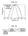
- FIG. 14 compares the filter transmission spectrum with the output pulse spectrum, for the laser of FIG. 11 ;
- FIG. 15 is a generalized representation of a waveguide amplifier system operating in the positive dispersion regime.
- FIG. 16 illustrates a generic example of a polarization-maintaining fiber laser system.
- FIG. 1 A schematic drawing of a polarization maintaining large-diameter fiber is shown in FIG. 1 .
- the fiber core has an elliptical shape in order to define the polarization axes of the fiber.
- the fiber comprises a circular (or non-uniform) inner 1 st cladding and a non-uniform (or circular) outside 2 nd cladding.
- the parentheses indicate that the locations of the circular and non-uniform claddings can be reversed.
- the refractive index of the 2 nd cladding is lower than the refractive index of the 1 st cladding.
- any cladding shape can be used for the non-uniform cladding, whether the non-uniform cladding is the 1 st or the 2 nd cladding.
- the 1 st cladding can consist of germania-doped silica
- the 2 nd cladding can consist of fluoride glass to obtain a maximum refractive index difference, though any glass compositions with appropriate refractive index differences can be used.
- the fiber can be produced by starting out with a circular perform, which is then machined on both sides to produce an oblong structure. By heating and some additional stretching, the perform can be transferred back to a circular structure, producing a circular inner cladding, taking advantage of surface tension. As a result the fiber core will be elliptical, and the inner cladding will be circular A 2 nd cladding can then be produced by over-sleaving the circular fiber perform with a substrate tube of the appropriate 2 nd cladding material (fluoro or borosilicate) and subsequently fusing the tube to the original fiber perform. The 2 nd cladding can be machined to produce an arbitrary shape for the outside of the 2 nd cladding. A third cladding (coating) with a lower refractive index is then produced by coating the 2 nd cladding with an appropriate polymer material. The refractive index profile of such a fiber is shown in FIG. 2 a.
- a 1 st cladding can be directly deposited around a heavily-germano, alumino-or phospho silicate doped fiber core during preform fabrication.
- This 1 st cladding is produced by reducing the doping level compared to the core.
- the cladding numerical aperture should be large (larger than 0.15) to enable coupling of large amounts of pump light and can have a circular or elliptical (not shown) cross-section.
- the outside cladding can then be made by appropriate machining of the preform substrate material, followed by coating as outlined above. The refractive index profile of such a fiber is shown in FIG. 2 b.
- the central section of the fiber described in FIG. 1 or the fiber core can be doped with any rare-earth doping material so as to enable the use of the fiber as a polarization- holding amplifier.
- the fiber design with a circular inner cladding as discussed above ensures a non-uniform absorption coefficient along the fiber length when end-pumping from the output end of a fiber amplifier is implemented as shown in FIG. 3 a .
- the signal light is injected from the left-hand side and the pump light is injected from the right-hand side, the output end of the fiber amplifier. Because of the reduced absorption of helical rays inside the inner cladding, the effective absorption coefficient of the pump light will decrease along the fiber.
- the effective signal gain per unit length increases strongly towards the output end of the amplifier, producing a structure with a large gain only in the output end section of the amplifier as illustrated in FIG. 3 b .
- L eff [1 ⁇ exp( ⁇ gL)]/g (for a constant gain g)
- a large gain at the end of an amplifier produces a short effective amplifier length and allows the generation of an optical signal with a correspondingly large peak power.
- a non-uniform second cladding, as well as scattering between the interface of the first and second claddings, provides efficient absorption for the light rays propagating in the second cladding.
- the 2 nd fiber cladding in FIG. 1 can be omitted, but the fiber should then have an outside diameter of >150 ⁇ m to minimize polarization mode-coupling in the fiber.
- the outside of the fiber can have an arbitrary shape.
- Optional stress producing regions ( FIG. 4 a ) or selective fiber holes ( FIG. 4 b ) can also be incorporated into the fiber cladding to obtain an optimum degree of birefringence as shown in FIGS. 4 a and 4 b .
- the stress producing regions within the inner cladding (or the air holes) can have different shapes as illustrated in FIG. 4 b . In the absence of stress-producing regions or air holes, the ratio of the major/minor axis of the fiber core should be larger than 1.1.
- a circular fiber core In the presence of stress-producing regions, a circular fiber core can be used. With or without the inclusion of a 2 nd cladding, the overall outside diameter of the fiber should be larger than 150 ⁇ m and the fiber birefringence should be larger than 1 ⁇ 10 ⁇ 6 .
- the outside of the fiber can be surrounded by a polymer coating for fiber protection.
- a soft inner coating and a hard outer coating can be applied to the outside of the fiber.
- a possible selection of such coating materials is the use of a silicone inner coating and an acrylic outer coating. In this case an arbitrary fiber diameter can be used and a second cladding can be omitted. Two examples of such polarization holding fibers are shown in FIGS. 5 , where FIG.
- FIG. 5 a comprises an elliptical core and FIG. 5 b comprises a circular core surrounded by slightly asymmetric air holes.
- the central section of the fibers described in FIGS. 4 and 5 or the fiber core can be doped with any rare-earth doping material so as to enable the use of the fiber as a polarization holding amplifier.
- the typical polarization holding ability of fibers of the design shown in FIG. 4 a is listed in table 1 below.
- the fibers had approximately circular cores and all but fiber 1 incorporated stress-producing regions in the cladding.
- the fibers were 2 m long and were coiled onto spools with a diameter of 10 cm.
- the fibers were “double cladded”, comprising a 1 st cladding and a low-index polymer coating. A true 2 nd cladding was absent.
- the fibers were doped with Yb with doping levels of about 2 mole %.
- the polarization extinction is the relative amount of light that couples into the 2 nd polarization axis (measured at the fiber output end) of the fiber when the light is coupled into the input end in the 1 st polarization axis of the fiber.
- This intermediate regime encompasses birefringence values from 1 ⁇ 10 ⁇ 6 ⁇ 1 ⁇ 10 ⁇ 4 .
- fibers with this range of birefringence as intermediate birefringence fibers.
- the corresponding polarization beat lengths for the range of intermediate birefringence are between 100 cm and 1.0 cm, respectively.
- Polarization Polarization Fiber Fiber core beat length extinction Mode- Fiber diameter diameter Bire- at 1.05 ⁇ m after 2 m of locking # Stress ( ⁇ m) ( ⁇ m) fringence (cm) fiber stability 1 No stress 135 8 ⁇ 1 ⁇ 10 ⁇ 6 Not applicable stable 2 Very low 135 7 8 ⁇ 10 ⁇ 6 13 20/1 stable stress 3 Low Stress 125 7 1.6 ⁇ 10 ⁇ 5 6.5 100/1 stable 4 Low Stress 200 11 1.6 ⁇ 10 ⁇ 5 6.5 1000/1 stable 5 High Stress 100 6 4.2 ⁇ 10 ⁇ 5 2.5 100/1 Not- stable 6 High Stress 125 7.5 4.2 ⁇ 10 ⁇ 5 2.5 1000/1 Not- stable
- Efficient double-clad fibers can also be constructed by implementation of fibers with only one inner cladding and an outside cladding in the form of a polymer coating.
- an inner cladding shape in the form of a pentagon can be implemented as shown in FIG. 6 a ).
- the core can be multi-mode or single-mode.
- Such a cladding shape has small internal angles optimizing pump mode coupling and optimizing pump absorption inside the fiber. A large pump absorption is clearly useful for application of such fibers as high-power pulse amplifiers.
- a cladding shape in the form of a heptagon is equally possible as shown in FIG. 6 b ).
- a heptagon produces less pump mode coupling because of the smaller internal angles between the cladding planes, however, because of the close proximity of such a structure to a perfect circle, such a fiber is easier to splice, which is preferable in many applications.
- these two cladding shapes are symmetrical, but they do not tile a plane.
- such claddings enable mode-coupling of the pump modes inside the fiber leading to efficient absorption of helical rays. Due to the resulting uniform pump absorption, such fibers would not necessarily be used to obtain the highest possible powers when used as amplifiers for high peak power pulses.
- a polygon with 9, sides or 11, or, generally, (2n ⁇ 1), where n>4 sides can also be implemented (not shown).
- Improved absorption of helical rays can also be obtained by using a non-diametrically symmetric, non-equilateral hexagonal cladding shape as shown in FIG. 6 c ). Because of the reduced level of symmetry of such a cladding shape, even better pump mode coupling is obtained leading to a maximization of pump mode absorption.
- non-circular stress producing regions can be added.
- non-circular (or circular) stress producing regions can be added to the fiber cross section from FIG. 6 a , as shown in FIG. 7 a .
- Circular stress producing regions in conjunction with a pentagon fiber are not separately shown.
- Such fibers can have a single-mode or a multi-mode core.
- Circular stress producing regions are shown in conjunction with a heptagon fiber in FIG. 7 b .
- circular stress production can be incorporated into any double-clad or triple clad fiber, where both the 1 st inner and/or the 2 nd inner cladding can be non-uniform.
- FIG. 7 c is an additional implementation of a polarization maintaining fiber, incorporating a diametrically symmetric, non-equilateral hexagonal cladding shape.
- the fiber core may be multi-mode or single-mode.
- the fibers listed in table 1 were also tested as part of a cavity of a passively modelocked Yb fiber laser.
- the generalized illustration of the modelocked system of the invention is shown in FIG. 8 .
- the fibers were side-pumped with spatially incoherent light from a high-power pump laser coupled into the cladding.
- the bandpass filter (F) had a spectral bandwidth of 3 nm centered at 1040 nm.
- the polarizer (P) was aligned with one of the polarization axes of the fiber.
- the saturable absorber was a film of AlInGaAs with a thickness of 0.64 ⁇ m and a band edge of 1040 nm deposited on a film of gold that was attached to a heat sink.
- the carrier life-time of the absorber was of the order of 1 ps.
- the 4% reflection from the straight-cleaved intra-cavity fiber end served as the output coupler mirror.
- the laser produced pulses at a repetition rate of ⁇ 50 MHz with average powers of 10-40 mW depending on the core size of the fiber.
- the generated pulse width was typically 2 ps.
- fibers with diameters >125 ⁇ m make them more rigid, also minimizing polarization mode-coupling in the presence of fiber bends, i.e. large diameter fibers enable coiling with a smaller loss of polarization extinction compared to smaller diameter fibers.
- two fiber claddings and/or two (or more) appropriately selected layers of coating material can also be implemented.
- the cavity shown in FIG. 8 also produced stable pulses in multi-mode fiber with a core diameter of 11 ⁇ m (fiber #4), which supported more than 1 transverse mode.
- fiber #4 a fiber taper was incorporated into the fiber near a fiber end as a mode-filter. The taper is not separately shown.
- the core diameter is correspondingly tapered from 11 ⁇ m to 5.5 ⁇ m, allowing for single-mode operation.
- the fundamental mode in the fiber could typically be excited with an efficiency of 99%.
- the life-time of the saturable absorber had to be shorter than the single-pass group delay between the fundamental and the next higher-order mode in the fiber.
- next higher-order mode couples a small pulse into the fundamental mode of the fiber at each end of the cavity.
- This small pulse gets time delayed with respect to the main pulse.
- the small pulse generates an injection signal for the growth of a second time-delayed pulse. After another pass, yet another time delayed pulse is generated and so on.
- the growth of any secondary pulses is prevented, however, if the secondary pulse is strongly absorbed by the saturable absorber, which requires that the saturable absorber life-time be shorter than the single-pass group delay between the fundamental and the next higher-order mode.
- the saturable absorber life time should be smaller than the time delay between the spurious pulse (generated by the spurious reflection) and the main pulse in the cavity.
- FIG. 9 a modelocked fiber laser incorporating two sections of highly birefringent fiber inside a cavity is shown.
- the polarization axes of the fiber sections are assumed to be aligned parallel or anti-parallel with respect to each other. Due to small unavoidable misalignments of the polarization axes, small pulses propagating in the “wrong” polarization axis are thus generated at each connection between the fiber sections. Pulse stability hence requires that the single-pass group-delay between the polarization eigenmodes in each fiber section is larger than the generated pulse width.
- the polarization group delay is ⁇ 3.5 ps in a 2 m fiber section.
- the saturable absorber should thus have a life-time of less than 3.5 ps to ensure optimum stability of the modelocked laser.
- the reduced degree of mode-coupling in multi-layer coated fibers or fibers with outside diameters >125 ⁇ m also allows an improvement in the polarization holding ability of isotropic tightly tension coiled fibers as suggested in Fermann et al., U.S. Pat. No. 6,072,811. Since such fibers are less sensitive to micro-bending induced mode-coupling, improved polarization extinction can be obtained.
- Such fibers can be used as a direct replacement of the intermediate or high birefringence fibers of FIG. 8.
- a modelocked fiber laser cavity incorporating a tension-coiled approximately isotropic fiber is displayed in FIG. 10 .
- additional waveplates w 1 , w 2
- the gain fiber can incorporate intermediate birefringent, highly birefringent or multi-mode fiber.
- the straight-cleaved fiber end can be coated with a dielectric mirror in order to reduce the amount of output coupling. Alternatively, an external mirror could also be used as a an output coupler.
- Dispersion compensating elements such as one or two bulk grating pairs, prism pairs or grism pairs can also be incorporated into the cavity to produce shorter pulses and to simplify modelocked operation.
- saturable absorber mirror SA
- an additional optical modulator could be incorporated into the cavity (not separately shown) to enable short pulse generation via active modelocking.
- An optical filter (F) can also be part of such a cavity.
- a modelocked oscillator can also be constructed using a fiber grating written directly into the gain fiber for further integration of the cavity components as shown in FIG. 12 .
- the gain fiber can incorporate intermediate birefringent, highly birefringent or multi-mode (MM) fiber.
- MM multi-mode
- the grating can be chirped or unchirped depending on the desired output characteristics of the laser. If the pump light is injected from the saturable absorber fiber end or if a form of side-pumping is employed, an additional amplifier fiber could be spliced to the fiber grating end of the cavity for additional signal amplification, resulting in a very compact high-power fiber laser. Such a system configuration is not separately shown.
- the filter (F) has a bandwidth (FWHM) less than the gain bandwidth (FWHM) of the fiber.
- FWHM bandwidth
- the gain fiber has positive dispersion.
- the fiber is polarization maintaining and intermediate birefringence and high birefringence fiber or MM fiber can be employed.
- the polarizer is aligned with one of the polarization axes of the fiber.
- the formation of parabolic pulses is then enabled when using a highly absorptive saturable absorber.
- the linear absorption of the saturable absorber is 90%. If the saturable absorber is also operated in deep saturation, the tendency of high-power pulses to break up inside the cavity is suppressed. As a result linearly chirped high-power parabolic pulses can be generated. Because parabolic pulses are relatively insensitive to self-phase modulation, the energy of parabolic pulses can be much higher compared to soliton and gaussian shaped pulses.
- a key parameter for obtaining parabolic pulses is a generated spectral bandwidth of the output pulses, which is larger than the intra-cavity filter bandwidth, a feature that is not achievable with other modelocking techniques.
- a typical example of the obtainable pulse spectrum in comparison to the intra-cavity filter bandwidth for a modelocked Yb oscillator is shown in FIG. 14 .
- the increased spectral bandwidth in comparison to the intra-cavity filter bandwidth is an ideal measure of the degree by which the intra-cavity pulses have acquired a parabolic pulse shape.
- the generation of high power parabolic pulses is not limited to Fabry-Perot cavities as shown, but any waveguide laser cavity design with an intra-cavity positive dispersion amplifier waveguide and a narrow bandpass filter can be implemented.
- the formation of approximately parabolically shaped pulses occurs.
- Optimum stability for parabolic pulse formation is ensured when the life-time of the absorber is shorter than 5 times the maximum width of the generated pulses, where a saturable absorber life-time of less than 1 times the width of the generated pulses is preferred.
- Polarization maintaining intermediate birefringence fibers can also be used in other fiber laser or amplifier applications.
- a generic example of such a fiber as a polarization maintaining amplifier is shown in FIG. 16 .
- the signal light is coupled into the PM amplifier via a polarization maintaining fiber and polarization maintaining fiber splice.
- a splice can be accomplished by rotating the two fibers appropriately before splicing.
- the amplifier can be end-pumped or side pumped.
- the pump light can also be injected via optical couplers located at either end of the amplifier fiber or anywhere within the amplifier fiber.
Landscapes
- Physics & Mathematics (AREA)
- Electromagnetism (AREA)
- Engineering & Computer Science (AREA)
- Plasma & Fusion (AREA)
- Optics & Photonics (AREA)
- Lasers (AREA)
- Optical Fibers, Optical Fiber Cores, And Optical Fiber Bundles (AREA)
Priority Applications (11)
| Application Number | Priority Date | Filing Date | Title |
|---|---|---|---|
| US09/809,248 US6954575B2 (en) | 2001-03-16 | 2001-03-16 | Single-polarization high power fiber lasers and amplifiers |
| DE10262414.3A DE10262414B3 (de) | 2001-03-16 | 2002-03-14 | Passiv modengekoppelter Faserlaser |
| DE10211352A DE10211352A1 (de) | 2001-03-16 | 2002-03-14 | Einfachpolarisations-Hochleistungsfaserlaser und -verstärker |
| JP2002072975A JP4490619B2 (ja) | 2001-03-16 | 2002-03-15 | 偏光保持ファイバ、ファイバレーザ及びファイバ増幅器 |
| JP2005074104A JP4348309B2 (ja) | 2001-03-16 | 2005-03-15 | モードロックファイバレーザ |
| US11/109,711 US7782910B2 (en) | 2001-03-16 | 2005-04-20 | Single-polarization high power fiber lasers and amplifiers |
| JP2008040435A JP2008158547A (ja) | 2001-03-16 | 2008-02-21 | 偏光保持ファイバ、偏光保持ファイバレーザ、受動モードロックファイバレーザ、ファイバ増幅器及び光ファイバ |
| JP2009096761A JP4994415B2 (ja) | 2001-03-16 | 2009-04-13 | 受動モードロックファイバレーザ |
| JP2009142237A JP2009205174A (ja) | 2001-03-16 | 2009-06-15 | 偏光保持ファイバ、ファイバ増幅器及びファイバレーザ |
| US12/815,588 US8135048B2 (en) | 2001-03-16 | 2010-06-15 | Single-polarization high power fiber lasers and amplifiers |
| JP2012181613A JP5899084B2 (ja) | 2001-03-16 | 2012-08-20 | 偏光保持モードロックファイバレーザ発振器 |
Applications Claiming Priority (1)
| Application Number | Priority Date | Filing Date | Title |
|---|---|---|---|
| US09/809,248 US6954575B2 (en) | 2001-03-16 | 2001-03-16 | Single-polarization high power fiber lasers and amplifiers |
Related Child Applications (1)
| Application Number | Title | Priority Date | Filing Date |
|---|---|---|---|
| US11/109,711 Division US7782910B2 (en) | 2001-03-16 | 2005-04-20 | Single-polarization high power fiber lasers and amplifiers |
Publications (2)
| Publication Number | Publication Date |
|---|---|
| US20020172486A1 US20020172486A1 (en) | 2002-11-21 |
| US6954575B2 true US6954575B2 (en) | 2005-10-11 |
Family
ID=25200876
Family Applications (3)
| Application Number | Title | Priority Date | Filing Date |
|---|---|---|---|
| US09/809,248 Expired - Lifetime US6954575B2 (en) | 2001-03-16 | 2001-03-16 | Single-polarization high power fiber lasers and amplifiers |
| US11/109,711 Expired - Fee Related US7782910B2 (en) | 2001-03-16 | 2005-04-20 | Single-polarization high power fiber lasers and amplifiers |
| US12/815,588 Expired - Fee Related US8135048B2 (en) | 2001-03-16 | 2010-06-15 | Single-polarization high power fiber lasers and amplifiers |
Family Applications After (2)
| Application Number | Title | Priority Date | Filing Date |
|---|---|---|---|
| US11/109,711 Expired - Fee Related US7782910B2 (en) | 2001-03-16 | 2005-04-20 | Single-polarization high power fiber lasers and amplifiers |
| US12/815,588 Expired - Fee Related US8135048B2 (en) | 2001-03-16 | 2010-06-15 | Single-polarization high power fiber lasers and amplifiers |
Country Status (3)
| Country | Link |
|---|---|
| US (3) | US6954575B2 (https=) |
| JP (6) | JP4490619B2 (https=) |
| DE (2) | DE10211352A1 (https=) |
Cited By (37)
| Publication number | Priority date | Publication date | Assignee | Title |
|---|---|---|---|---|
| US20030202547A1 (en) * | 1998-11-25 | 2003-10-30 | Fermann Martin E. | Multi-mode fiber amplifier |
| US20040218635A1 (en) * | 2003-01-24 | 2004-11-04 | Holger Schlueter | Fiber laser |
| US20050185260A1 (en) * | 1997-03-21 | 2005-08-25 | Imra America, Inc. | Microchip - Yb fiber hybrid optical amplifier for micro-machining and marking |
| US20050220431A1 (en) * | 2004-03-30 | 2005-10-06 | Fujitsu Limited | Device for canceling the wavelength dependence of the nonlinearity coefficient of microstructured fibers |
| US20050226580A1 (en) * | 2004-04-08 | 2005-10-13 | Samson Bryce N | Optical fiber for handling higher powers |
| US20050243409A1 (en) * | 1998-07-16 | 2005-11-03 | Imra America, Inc. | Microchip - Yb fiber hybrid optical amplifier for micro-machining and marking |
| US20050254765A1 (en) * | 2004-05-03 | 2005-11-17 | Martin Seifert | Optical fiber having reduced defect density |
| US20050265678A1 (en) * | 2004-05-03 | 2005-12-01 | Manyam Upendra H | Optical fiber for delivering optical energy to or from a work object |
| US20060031875A1 (en) * | 2004-08-05 | 2006-02-09 | Samsung Electronics Co., Ltd. | Apparatus and method for supplying electronic program guide for video on demand services |
| US20060088261A1 (en) * | 2004-10-21 | 2006-04-27 | Berkey George E | Rare earth doped single polarization double clad optical fiber and a method for making such fiber |
| US20060198590A1 (en) * | 2004-08-05 | 2006-09-07 | Nufern | Fiber Optic Article with Inner Region |
| US20070177846A1 (en) * | 2006-01-30 | 2007-08-02 | Xin Chen | Rare earth doped double clad optical fiber with plurality of air holes and stress rods |
| US20070242473A1 (en) * | 2006-04-13 | 2007-10-18 | Lg Electronics Inc. | Light guide, method and apparatus for manufacturing the same, and illuminating system having the same |
| US20070280304A1 (en) * | 2006-06-05 | 2007-12-06 | Jochen Deile | Hollow Core Fiber Laser |
| US20080095199A1 (en) * | 2004-01-30 | 2008-04-24 | Nufern | Method and Apparatus for Providing Light Having a Selected Polarization With an Optical Fiber |
| US20080193093A1 (en) * | 2007-02-12 | 2008-08-14 | Furukawa Electric North America Inc | Optical fiber configuration for dissipating stray light |
| US7440181B2 (en) | 2006-08-02 | 2008-10-21 | Coherent, Inc. | Double-pass fiber amplifier |
| US20090092157A1 (en) * | 2007-10-09 | 2009-04-09 | Ipg Photonics Corp. | Powerful fiber laser system |
| US7656578B2 (en) | 1997-03-21 | 2010-02-02 | Imra America, Inc. | Microchip-Yb fiber hybrid optical amplifier for micro-machining and marking |
| US20100079855A1 (en) * | 2008-04-22 | 2010-04-01 | Liang Dong | Multi-clad optical fibers |
| US20100079854A1 (en) * | 2007-08-28 | 2010-04-01 | Fujikura Ltd. | Rare-earth doped core multi-clad fiber, fiber amplifier, and fiber laser |
| US7876495B1 (en) | 2007-07-31 | 2011-01-25 | Lockheed Martin Corporation | Apparatus and method for compensating for and using mode-profile distortions caused by bending optical fibers |
| US20110081123A1 (en) * | 2008-01-17 | 2011-04-07 | Institut National D'optique | Multi-cladding fiber |
| US8089689B1 (en) | 2006-11-30 | 2012-01-03 | Lockheed Martin Corporation | Apparatus and method for optical gain fiber having segments of differing core sizes |
| US20120275015A1 (en) * | 2010-02-22 | 2012-11-01 | Fujikura Ltd. | Amplifying optical fiber and optical fiber amplifier |
| RU2468400C2 (ru) * | 2006-11-29 | 2012-11-27 | Кэскейд Текнолоджиз Лимитед | Устройство возмущения многомодового оптического волокна |
| USRE44288E1 (en) | 2004-02-20 | 2013-06-11 | Corning Incorporated | Optical fiber and method for making such fiber |
| US8537864B2 (en) | 2004-03-31 | 2013-09-17 | Imra America, Inc. | High power short pulse fiber laser |
| EP2763247A2 (en) | 2006-05-11 | 2014-08-06 | SPI Lasers UK Limited | Apparatus for providing optical radiation |
| US20140314105A1 (en) * | 2013-04-19 | 2014-10-23 | Ipg Photonics Corporation | Fiber with Asymmetrical Core and Method for Manufacturing Same |
| US8873908B2 (en) * | 2010-08-23 | 2014-10-28 | Lockheed Martin Corporation | Optical-fiber array and method |
| WO2015077021A1 (en) | 2013-11-22 | 2015-05-28 | Imra America, Inc | Polarizing and polarization maintaining leakage channel fibers |
| US9240670B2 (en) | 2011-03-07 | 2016-01-19 | Imra America, Inc. | Optical pulse source with increased peak power |
| US9293892B2 (en) | 2012-09-05 | 2016-03-22 | Seiko Epson Corporation | Short optical pulse generator, terahertz wave generation device, camera, imaging apparatus, and measurement apparatus |
| US10096962B2 (en) | 2003-06-03 | 2018-10-09 | Imra America, Inc. | All-fiber chirped pulse amplification systems |
| US20220043221A1 (en) * | 2013-06-14 | 2022-02-10 | Chiral Photonics, Inc. | Multichannel optical coupler array |
| US12210185B2 (en) | 2020-02-24 | 2025-01-28 | Chiral Photonics, Inc. | Wavelength division multiplexers for space division multiplexing (SDM-WDM devices) |
Families Citing this family (130)
| Publication number | Priority date | Publication date | Assignee | Title |
|---|---|---|---|---|
| US7068900B2 (en) * | 1999-12-24 | 2006-06-27 | Croteau Andre | Multi-clad doped optical fiber |
| US6885683B1 (en) | 2000-05-23 | 2005-04-26 | Imra America, Inc. | Modular, high energy, widely-tunable ultrafast fiber source |
| US7190705B2 (en) | 2000-05-23 | 2007-03-13 | Imra America. Inc. | Pulsed laser sources |
| FR2811437A1 (fr) * | 2000-07-06 | 2002-01-11 | Cit Alcatel | Fibre optique a pompage par la gaine et procede de fabrication d'une telle fibre |
| US7973936B2 (en) | 2001-01-30 | 2011-07-05 | Board Of Trustees Of Michigan State University | Control system and apparatus for use with ultra-fast laser |
| US7583710B2 (en) | 2001-01-30 | 2009-09-01 | Board Of Trustees Operating Michigan State University | Laser and environmental monitoring system |
| US8208505B2 (en) | 2001-01-30 | 2012-06-26 | Board Of Trustees Of Michigan State University | Laser system employing harmonic generation |
| US7567596B2 (en) | 2001-01-30 | 2009-07-28 | Board Of Trustees Of Michigan State University | Control system and apparatus for use with ultra-fast laser |
| US7450618B2 (en) | 2001-01-30 | 2008-11-11 | Board Of Trustees Operating Michigan State University | Laser system using ultrashort laser pulses |
| US6954575B2 (en) | 2001-03-16 | 2005-10-11 | Imra America, Inc. | Single-polarization high power fiber lasers and amplifiers |
| US6816513B2 (en) * | 2001-04-02 | 2004-11-09 | Apollo Instruments, Inc. | High power high efficiency cladding pumping fiber laser |
| US6825974B2 (en) * | 2001-11-06 | 2004-11-30 | Sandia National Laboratories | Linearly polarized fiber amplifier |
| US6707957B1 (en) * | 2001-12-18 | 2004-03-16 | Nortel Networks Limited | Compensating for polarisation mode dispersion in optical transmission fibers |
| US7068896B1 (en) | 2002-02-07 | 2006-06-27 | Northwestern University | Method and system for the controlled production of polarization mode dispersion |
| US7116887B2 (en) * | 2002-03-19 | 2006-10-03 | Nufern | Optical fiber |
| JP2003283016A (ja) * | 2002-03-25 | 2003-10-03 | Aisin Seiki Co Ltd | 受動型モードロック・ファイバーレーザー |
| US6842570B2 (en) * | 2002-12-11 | 2005-01-11 | Northrop Grumman Corporation | Method for coupling diode array light into an optical fiber |
| US7110647B2 (en) * | 2003-01-17 | 2006-09-19 | Nufern | Multimode polarization maintaining double clad fiber |
| JP4301822B2 (ja) * | 2003-01-24 | 2009-07-22 | 富士通株式会社 | 偏波モード分散補償機能を有する光増幅器 |
| EP1586145B1 (en) | 2003-01-24 | 2006-06-07 | Trumpf, Inc. | Side-pumped fiber laser |
| US6959022B2 (en) * | 2003-01-27 | 2005-10-25 | Ceramoptec Gmbh | Multi-clad optical fiber lasers and their manufacture |
| US7257302B2 (en) * | 2003-06-03 | 2007-08-14 | Imra America, Inc. | In-line, high energy fiber chirped pulse amplification system |
| US7120340B2 (en) * | 2003-06-19 | 2006-10-10 | Corning Incorporated | Single polarization optical fiber laser and amplifier |
| GB0314817D0 (en) * | 2003-06-25 | 2003-07-30 | Southampton Photonics Ltd | Apparatus for providing optical radiation |
| US7113327B2 (en) * | 2003-06-27 | 2006-09-26 | Imra America, Inc. | High power fiber chirped pulse amplification system utilizing telecom-type components |
| US7280730B2 (en) | 2004-01-16 | 2007-10-09 | Imra America, Inc. | Large core holey fibers |
| WO2005074573A2 (en) | 2004-01-30 | 2005-08-18 | Nufern | Method and apparatus for providing light having a selected polarization with an optical fiber |
| KR100617713B1 (ko) | 2004-02-12 | 2006-08-28 | 삼성전자주식회사 | 다공 광섬유의 제조방법 |
| US6970632B2 (en) * | 2004-05-03 | 2005-11-29 | Corning Incorporated | Solid type single polarization fiber and apparatus |
| CA2466970A1 (en) * | 2004-05-12 | 2005-11-12 | Coractive High-Tech Inc. | Double-clad optical fibers |
| DE102004027625A1 (de) | 2004-06-05 | 2006-01-05 | Trumpf Laser Gmbh + Co. Kg | Hochleistungs-Faserlaserverstärker und -Faserlaseroszillator |
| US7062137B2 (en) * | 2004-08-05 | 2006-06-13 | Nufern | Fiber optic article including fluorine |
| EP1782111A4 (en) * | 2004-08-05 | 2008-04-16 | Nufern | OPTIC FIBER ARTICLE |
| US7924892B2 (en) * | 2004-08-25 | 2011-04-12 | Kla-Tencor Technologies Corporation | Fiber amplifier based light source for semiconductor inspection |
| US7280728B2 (en) * | 2004-10-22 | 2007-10-09 | Corning Incorporated | Rare earth doped single polarization double clad optical fiber with plurality of air holes |
| US7508853B2 (en) | 2004-12-07 | 2009-03-24 | Imra, America, Inc. | Yb: and Nd: mode-locked oscillators and fiber systems incorporated in solid-state short pulse laser systems |
| US20060139727A1 (en) * | 2004-12-28 | 2006-06-29 | Rachid Gafsi | Hybrid fiber polarization dependent isolator, and laser module incorporating the same |
| DK1846784T3 (en) * | 2004-12-30 | 2016-10-03 | Imra America Inc | Fiber with photonic band gap |
| FR2881845B1 (fr) * | 2005-02-04 | 2007-06-01 | Centre Nat Rech Scient | Fibre optique composite pour laser a confinement d'ondes de pompe et de laser, applications aux lasers |
| EP1851532A1 (en) | 2005-02-14 | 2007-11-07 | Board of Trustees of Michigan State University | Ultra-fast laser system |
| US7787729B2 (en) | 2005-05-20 | 2010-08-31 | Imra America, Inc. | Single mode propagation in fibers and rods with large leakage channels |
| GB2427910B (en) * | 2005-07-02 | 2008-03-12 | Sensor Highway Ltd | Fiber optic temperature and pressure sensor and system incorporating same |
| US7391561B2 (en) * | 2005-07-29 | 2008-06-24 | Aculight Corporation | Fiber- or rod-based optical source featuring a large-core, rare-earth-doped photonic-crystal device for generation of high-power pulsed radiation and method |
| DE102005042073B4 (de) * | 2005-08-31 | 2010-11-11 | Fraunhofer-Gesellschaft zur Förderung der angewandten Forschung e.V. | Faserlaser |
| US7778290B2 (en) * | 2005-10-02 | 2010-08-17 | Elbit Systems Electro-Optics Elop Ltd. | Fiber lasers |
| US7809222B2 (en) | 2005-10-17 | 2010-10-05 | Imra America, Inc. | Laser based frequency standards and their applications |
| US8618470B2 (en) | 2005-11-30 | 2013-12-31 | Board Of Trustees Of Michigan State University | Laser based identification of molecular characteristics |
| US7570856B1 (en) * | 2005-12-07 | 2009-08-04 | Lockheed Martin Corporation | Apparatus and method for an erbium-doped fiber for high peak-power applications |
| GB2434483A (en) * | 2006-01-20 | 2007-07-25 | Fianium Ltd | High-Power Short Optical Pulse Source |
| US8120778B2 (en) | 2009-03-06 | 2012-02-21 | Imra America, Inc. | Optical scanning and imaging systems based on dual pulsed laser systems |
| US8571075B2 (en) * | 2010-11-29 | 2013-10-29 | Imra America, Inc. | Frequency comb source with large comb spacing |
| JP2007273600A (ja) * | 2006-03-30 | 2007-10-18 | Furukawa Electric Co Ltd:The | 光ファイバレーザ |
| US9018562B2 (en) | 2006-04-10 | 2015-04-28 | Board Of Trustees Of Michigan State University | Laser material processing system |
| GB2444091A (en) * | 2006-11-24 | 2008-05-28 | Gsi Group Ltd | A Laser Amplifier |
| FR2903817B1 (fr) * | 2006-07-13 | 2010-06-25 | Femlight | Dispositif laser a fibre optique de puissance |
| FR2909776B1 (fr) * | 2006-12-12 | 2009-06-05 | Centre Nat Rech Scient | Fibre optique dopee a symetrie spatiale brisee |
| US7496260B2 (en) | 2007-03-27 | 2009-02-24 | Imra America, Inc. | Ultra high numerical aperture optical fibers |
| WO2009014623A1 (en) * | 2007-07-20 | 2009-01-29 | Corning Incorporated | Large-mode-area optical fiber |
| US7924500B1 (en) * | 2007-07-21 | 2011-04-12 | Lockheed Martin Corporation | Micro-structured fiber profiles for mitigation of bend-loss and/or mode distortion in LMA fiber amplifiers, including dual-core embodiments |
| US7983312B2 (en) | 2007-08-09 | 2011-07-19 | Raytheon Company | Method and apparatus for generation and amplification of light in a semi-guiding high aspect ratio core fiber |
| CN103246014B (zh) * | 2007-09-26 | 2015-12-23 | Imra美国公司 | 玻璃大芯径光纤 |
| US8311069B2 (en) | 2007-12-21 | 2012-11-13 | Board Of Trustees Of Michigan State University | Direct ultrashort laser system |
| US7991022B1 (en) * | 2008-01-16 | 2011-08-02 | Calmar Optcom, Inc. | Optical pulse amplification based on stimulated Raman scattering |
| US9063289B1 (en) | 2008-06-30 | 2015-06-23 | Nlight Photonics Corporation | Multimode fiber combiners |
| US9857536B2 (en) * | 2008-07-14 | 2018-01-02 | Chiral Photonics, Inc. | Optical component assembly for use with an optical device |
| US8636085B2 (en) * | 2008-08-20 | 2014-01-28 | Foro Energy, Inc. | Methods and apparatus for removal and control of material in laser drilling of a borehole |
| US20170191314A1 (en) * | 2008-08-20 | 2017-07-06 | Foro Energy, Inc. | Methods and Systems for the Application and Use of High Power Laser Energy |
| US9158070B2 (en) * | 2008-08-21 | 2015-10-13 | Nlight Photonics Corporation | Active tapers with reduced nonlinearity |
| US9285541B2 (en) | 2008-08-21 | 2016-03-15 | Nlight Photonics Corporation | UV-green converting fiber laser using active tapers |
| DK2677609T3 (da) * | 2008-11-17 | 2019-07-22 | Raytheon Co | Fremgangsmåde og indretning til generering og forstærkning af lys i en halvledende kernefiber med højt aspektforhold |
| EP2211430A3 (en) | 2009-01-23 | 2015-05-27 | Board of Trustees of Michigan State University | Laser autocorrelation system |
| JP2010177469A (ja) * | 2009-01-29 | 2010-08-12 | Furukawa Electric Co Ltd:The | 光ファイバレーザおよび光ファイバ増幅器 |
| US8861075B2 (en) | 2009-03-05 | 2014-10-14 | Board Of Trustees Of Michigan State University | Laser amplification system |
| JP2010258120A (ja) * | 2009-04-23 | 2010-11-11 | Fujifilm Corp | 超短波パルス光源およびそれを備えた2光子吸収記録媒体記録装置 |
| US9494738B1 (en) | 2009-05-28 | 2016-11-15 | Nlight, Inc. | Single mode fiber combiners |
| CN102576971A (zh) * | 2009-10-02 | 2012-07-11 | Imra美国公司 | 锁模激光器的光信号处理 |
| WO2011060817A1 (en) * | 2009-11-19 | 2011-05-26 | Vrije Universiteit Brussel | Optical fiber structure for sensors |
| US8902939B2 (en) * | 2010-01-22 | 2014-12-02 | Newport Corporation | Broadly tunable optical parametric oscillator |
| US8630322B2 (en) | 2010-03-01 | 2014-01-14 | Board Of Trustees Of Michigan State University | Laser system for output manipulation |
| JP2011203544A (ja) * | 2010-03-26 | 2011-10-13 | Fujikura Ltd | 光ファイバの接続方法、及び、光ファイバの接続構造 |
| CN101853301A (zh) | 2010-05-25 | 2010-10-06 | 华为技术有限公司 | 正则表达式匹配的方法和系统 |
| JP5478443B2 (ja) * | 2010-09-17 | 2014-04-23 | 日本電信電話株式会社 | 数モードファイバ |
| JP5710935B2 (ja) * | 2010-10-26 | 2015-04-30 | ソニー株式会社 | 半導体光増幅器組立体 |
| US8787410B2 (en) | 2011-02-14 | 2014-07-22 | Imra America, Inc. | Compact, coherent, high brightness light sources for the mid and far IR |
| DE102011000905A1 (de) * | 2011-02-24 | 2012-08-30 | Leica Microsystems Cms Gmbh | Pulsvereiniger für die verschiedenen Spektralfarben eines Superkontinuum-Lasers |
| US8971358B2 (en) | 2011-03-14 | 2015-03-03 | Imra America, Inc. | Broadband generation of mid IR, coherent continua with optical fibers |
| JP5930316B2 (ja) * | 2011-03-31 | 2016-06-08 | 国立大学法人大阪大学 | 光ファイバ、ファイバレーザおよび光ファイバの作製方法 |
| US8787411B2 (en) | 2011-06-21 | 2014-07-22 | Cornell University | Mode-locked fiber laser based on narrowband optical spectral filtering and amplifier similaritons |
| US8811784B2 (en) * | 2011-10-04 | 2014-08-19 | Furukawa Electric Co., Ltd. | Optical fiber and optical transmission system |
| US9484706B1 (en) | 2012-06-12 | 2016-11-01 | Nlight, Inc. | Tapered core fiber manufacturing methods |
| DE102012012982A1 (de) * | 2012-06-29 | 2014-01-02 | Fraunhofer-Gesellschaft zur Förderung der angewandten Forschung e.V. | Laseranordnung mit Faserverstärker |
| DE102012113029A1 (de) * | 2012-12-21 | 2014-06-26 | Fraunhofer-Gesellschaft zur Förderung der angewandten Forschung e.V. | Kurzpulslasersystem |
| WO2014105756A1 (en) | 2012-12-31 | 2014-07-03 | Nlight Photonics Corporation | Spatially stable high brightness fiber |
| WO2014105757A1 (en) | 2012-12-31 | 2014-07-03 | Nlight Photonics Corporation | All fiber low dynamic pointing high power lma fiber amplifier |
| US8995487B1 (en) * | 2013-02-11 | 2015-03-31 | Nlight Photonics Corporation | Laser driver subsystem |
| DE102013102891B4 (de) * | 2013-03-21 | 2016-09-15 | Laserline Gesellschaft für Entwicklung und Vertrieb von Diodenlasern mbH | Laseranordnung |
| DE102013102880B4 (de) * | 2013-03-21 | 2016-09-15 | Laserline Gesellschaft für Entwicklung und Vertrieb von Diodenlasern mbH | Laseranordnung |
| US10126494B2 (en) * | 2013-06-14 | 2018-11-13 | Chiral Photonics, Inc. | Configurable polarization mode coupler |
| US9817191B2 (en) * | 2013-06-14 | 2017-11-14 | Chiral Photonics, Inc. | Multichannel optical coupler array |
| US10838155B2 (en) | 2013-06-14 | 2020-11-17 | Chiral Photonics, Inc. | Multichannel optical coupler |
| US11156781B2 (en) * | 2013-06-14 | 2021-10-26 | Chiral Photonics, Inc. | Passive aligning optical coupler array |
| US10914891B2 (en) * | 2013-06-14 | 2021-02-09 | Chiral Photonics, Inc. | Multichannel optical coupler |
| US10101536B2 (en) * | 2013-06-14 | 2018-10-16 | Chiral Photonics, Inc. | Multichannel optical coupler array |
| US10564348B2 (en) * | 2013-06-14 | 2020-02-18 | Chiral Photonics, Inc. | Passive aligning optical coupler array |
| DE112014005158B4 (de) | 2013-11-12 | 2022-02-17 | Imra America, Inc. | Kompakte faserbasierte Kurzpuls-Laserquellen |
| US9341761B2 (en) * | 2014-03-18 | 2016-05-17 | Kla-Tencor Corporation | Switchable laser and fiber based lamphouse for optimal power output in different wavelength bands and pixel sizes |
| US9557625B2 (en) | 2014-05-20 | 2017-01-31 | The United States Of America, As Represented By The Secretary Of Commerce | Fiber frequency comb article |
| CN104158080A (zh) * | 2014-08-22 | 2014-11-19 | 穆林冉 | 一种光纤激光器及其种子源 |
| CN107005018B (zh) * | 2014-10-02 | 2019-09-20 | 瑞士苏黎世联邦理工学院 | 脉冲激光器 |
| CZ305888B6 (cs) * | 2015-02-05 | 2016-04-20 | Ăšstav fotoniky a elektroniky AV ÄŚR, v. v. i. | Zesilovací modul, způsob jeho výroby a pláštěm čerpané optické zařízení jej obsahující |
| US10359563B2 (en) | 2015-03-20 | 2019-07-23 | Corning Incorporated | Few-mode optical fiber |
| EP3173747A1 (en) * | 2015-11-25 | 2017-05-31 | Nederlandse Organisatie voor toegepast- natuurwetenschappelijk onderzoek TNO | Cryogenic fiber optic sensor device |
| CN105571750A (zh) * | 2016-03-08 | 2016-05-11 | 武汉理工大学 | 一种分布式压力传感系统 |
| KR101796997B1 (ko) * | 2016-03-14 | 2017-11-13 | 서울시립대학교 산학협력단 | 포화 흡수체의 제조 방법 |
| CN106199826B (zh) * | 2016-08-03 | 2019-04-23 | 清华大学 | 保偏环形芯光纤 |
| DE102016118391B4 (de) * | 2016-09-28 | 2019-03-14 | Fraunhofer-Gesellschaft zur Förderung der angewandten Forschung e.V. | Kurzpulslasersystem |
| US10490966B1 (en) * | 2016-12-27 | 2019-11-26 | Northrop Grumman Systems Corporation | Optical fiber device |
| WO2019032227A2 (en) * | 2017-07-06 | 2019-02-14 | Lawrence Livermore National Security, Llc | NON-CIRCULAR OPTICAL FIBER AND MODEFORM CONVERTER, AND METHOD THEREOF |
| US10530114B2 (en) * | 2017-08-31 | 2020-01-07 | United States Of America As Represented By The Administrator Of Nasa | Polarization maintaining, large mode area (PMVLMA) erbium-doped optical fiber and amplifier |
| CN108761631B (zh) * | 2018-05-03 | 2020-06-23 | 烽火通信科技股份有限公司 | 一种掺镱光纤及其制造方法 |
| CN112352176B (zh) | 2018-05-04 | 2023-09-12 | 努布鲁有限公司 | 三包层光纤 |
| US10490968B1 (en) * | 2018-05-18 | 2019-11-26 | Ofs Fitel, Llc | Self-starting, passively modelocked figure eight fiber laser |
| JP2020194014A (ja) * | 2019-05-24 | 2020-12-03 | 株式会社フジクラ | 光ファイバ、及びレーザ装置 |
| CN110346865B (zh) * | 2019-06-12 | 2020-09-15 | 烽火通信科技股份有限公司 | 一种多波段使用的保偏光纤 |
| CN110165531A (zh) * | 2019-06-27 | 2019-08-23 | 深圳市创鑫激光股份有限公司 | 一种大模场三包层无源光纤、模式剥离器和光纤激光器 |
| JP7767326B2 (ja) * | 2020-01-29 | 2025-11-11 | アンプリコニックス オイ | 低複屈折アクティブ光ファイバ |
| JP7786667B2 (ja) * | 2021-06-11 | 2025-12-16 | 三菱重工業株式会社 | レーザ増幅媒体およびレーザ増幅媒体の製造方法 |
| CN113589424B (zh) | 2021-07-07 | 2022-05-17 | 燕山大学 | 一种保偏色散补偿微结构光纤 |
| CN115072987B (zh) * | 2022-08-22 | 2023-01-03 | 中国电子科技集团公司第四十六研究所 | 一种八角形内包层结构有源光纤制备方法 |
| WO2024195010A1 (ja) * | 2023-03-20 | 2024-09-26 | 日本電信電話株式会社 | 単結晶ファイバ導波路 |
Citations (13)
| Publication number | Priority date | Publication date | Assignee | Title |
|---|---|---|---|---|
| US4815079A (en) | 1987-12-17 | 1989-03-21 | Polaroid Corporation | Optical fiber lasers and amplifiers |
| US4896942A (en) * | 1989-02-03 | 1990-01-30 | Minnesota Mining And Manufacturing Company | Polarization-maintaining optical fiber |
| US5450427A (en) | 1994-10-21 | 1995-09-12 | Imra America, Inc. | Technique for the generation of optical pulses in modelocked lasers by dispersive control of the oscillation pulse width |
| US5494941A (en) | 1992-02-11 | 1996-02-27 | Basf Aktiengesellschaft | Preparation of chlorofluorocarbon-free flexible polyurethane foams using diphenylmethane diisocyanate-based polyisocyanate mixtures containing urethane groups, and modified polyisocyanate mixtures of the type |
| US5513194A (en) | 1994-06-30 | 1996-04-30 | Massachusetts Institute Of Technology | Stretched-pulse fiber laser |
| US5553163A (en) | 1991-12-26 | 1996-09-03 | Thomson-Csf | Polytomous segmentation process |
| US5627848A (en) | 1995-09-05 | 1997-05-06 | Imra America, Inc. | Apparatus for producing femtosecond and picosecond pulses from modelocked fiber lasers cladding pumped with broad area diode laser arrays |
| US5818630A (en) | 1997-06-25 | 1998-10-06 | Imra America, Inc. | Single-mode amplifiers and compressors based on multi-mode fibers |
| US5880877A (en) | 1997-01-28 | 1999-03-09 | Imra America, Inc. | Apparatus and method for the generation of high-power femtosecond pulses from a fiber amplifier |
| US5966491A (en) | 1995-11-22 | 1999-10-12 | Lucent Technologies Incorporated | Cladding-pumped fiber structure |
| US6072811A (en) | 1998-02-11 | 2000-06-06 | Imra America | Integrated passively modelocked fiber lasers and method for constructing the same |
| US6097741A (en) | 1998-02-17 | 2000-08-01 | Calmar Optcom, Inc. | Passively mode-locked fiber lasers |
| US6157763A (en) | 1998-01-28 | 2000-12-05 | Sdl, Inc. | Double-clad optical fiber with improved inner cladding geometry |
Family Cites Families (48)
| Publication number | Priority date | Publication date | Assignee | Title |
|---|---|---|---|---|
| US622916A (en) * | 1899-04-11 | Grinding-mill | ||
| JPS6053285B2 (ja) * | 1981-06-30 | 1985-11-25 | 日立電線株式会社 | 定偏波型光フアイバ |
| US4558921A (en) | 1982-02-25 | 1985-12-17 | At&T Bell Laboratories | Soliton fiber telecommunication systems |
| US5363463A (en) * | 1982-08-06 | 1994-11-08 | Kleinerman Marcos Y | Remote sensing of physical variables with fiber optic systems |
| JPS5992929A (ja) * | 1982-11-17 | 1984-05-29 | Nippon Telegr & Teleph Corp <Ntt> | 偏波保持光フアイバの製造方法 |
| JPS6136134A (ja) * | 1984-07-30 | 1986-02-20 | Nippon Telegr & Teleph Corp <Ntt> | 応力付与形偏波保持光フアイバ用母材の作製方法及び装置 |
| JPS638706A (ja) * | 1986-06-30 | 1988-01-14 | Nippon Telegr & Teleph Corp <Ntt> | 偏波保持光フアイバ |
| JP2579484B2 (ja) * | 1987-05-22 | 1997-02-05 | 日本電信電話株式会社 | 希土類添加光フアイバレ−ザ |
| JPS63297247A (ja) * | 1987-05-29 | 1988-12-05 | Toshiba Silicone Co Ltd | 光通信ガラスファイバ用被覆剤 |
| JPS6461076A (en) * | 1987-09-01 | 1989-03-08 | Fujikura Ltd | Optical fiber laser |
| JPH01314209A (ja) * | 1988-06-14 | 1989-12-19 | Sumitomo Electric Ind Ltd | 定偏波光ファイバ |
| JP3011286B2 (ja) * | 1991-06-04 | 2000-02-21 | 日本電信電話株式会社 | モード同期光ファイバレーザ装置 |
| JP2563697B2 (ja) * | 1991-08-30 | 1996-12-11 | 日本電信電話株式会社 | ファイバレーザ装置 |
| JP2579394B2 (ja) * | 1991-09-13 | 1997-02-05 | 日本電信電話株式会社 | 波長多重型モード同期レーザ装置 |
| US5477375A (en) | 1993-04-30 | 1995-12-19 | At&T Corp. | Optical soliton generator |
| US5689519A (en) * | 1993-12-20 | 1997-11-18 | Imra America, Inc. | Environmentally stable passively modelocked fiber laser pulse source |
| US5533163A (en) * | 1994-07-29 | 1996-07-02 | Polaroid Corporation | Optical fiber structure for efficient use of pump power |
| DE69519736T2 (de) * | 1994-08-23 | 2001-06-28 | British Telecommunications P.L.C., London | Erzeugung von dunkelimpulsen |
| JPH0870151A (ja) * | 1994-08-30 | 1996-03-12 | Fujitsu Ltd | モード同期レーザ |
| JP3314379B2 (ja) * | 1994-09-29 | 2002-08-12 | 日本電信電話株式会社 | レーザパルス発振器 |
| US5473458A (en) | 1994-12-27 | 1995-12-05 | At&T Corp. | Soliton data transmission using non-soliton transmitter |
| US5949491A (en) | 1995-10-24 | 1999-09-07 | Dicomit Imaging Systems Corp. | Ultrasound image management system |
| JP3350874B2 (ja) * | 1995-11-15 | 2002-11-25 | 日本電信電話株式会社 | レーザパルス発振器 |
| JP3484648B2 (ja) * | 1996-03-07 | 2004-01-06 | 日本電信電話株式会社 | 光伝送路及び光伝送システム |
| US5790722A (en) * | 1996-04-16 | 1998-08-04 | Hughes Electronics | High power optical fiber amplifier/laser system |
| JP3444464B2 (ja) * | 1996-05-27 | 2003-09-08 | 日本電信電話株式会社 | 短パルス光源 |
| JP3503795B2 (ja) * | 1996-09-18 | 2004-03-08 | 三菱電線工業株式会社 | 過飽和吸収体、及びこれを用いた光増幅器並びに光ファイバレーザ |
| US7576909B2 (en) | 1998-07-16 | 2009-08-18 | Imra America, Inc. | Multimode amplifier for amplifying single mode light |
| US6208458B1 (en) | 1997-03-21 | 2001-03-27 | Imra America, Inc. | Quasi-phase-matched parametric chirped pulse amplification systems |
| US6181463B1 (en) | 1997-03-21 | 2001-01-30 | Imra America, Inc. | Quasi-phase-matched parametric chirped pulse amplification systems |
| EP2648039A3 (en) * | 1997-03-21 | 2014-07-09 | Imra America, Inc. | High energy optical fiber amplifier for picosecond-nanosecond pulses for advanced material processing applications |
| GB9713422D0 (en) * | 1997-06-26 | 1997-08-27 | Secr Defence | Single mode optical fibre |
| US5907652A (en) * | 1997-09-11 | 1999-05-25 | Lucent Technologies Inc. | Article comprising an air-clad optical fiber |
| US5949941A (en) * | 1997-11-21 | 1999-09-07 | Lucent Technologies Inc. | Cladding-pumped fiber structures |
| US6288659B1 (en) * | 1998-02-27 | 2001-09-11 | The Regents Of The University Of California | Data conversion using time manipulation |
| KR100269040B1 (ko) * | 1998-04-28 | 2000-10-16 | 서원석 | 파장이동 레이저 광원 및 파장이동 레이저 광 생성방법 |
| US6275512B1 (en) | 1998-11-25 | 2001-08-14 | Imra America, Inc. | Mode-locked multimode fiber laser pulse source |
| JP2000187108A (ja) * | 1998-12-22 | 2000-07-04 | Toshiba Corp | 小型レーザー |
| AU771646B2 (en) * | 1999-02-19 | 2004-04-01 | Crystal Fibre A/S | Improvements in or relating to photonic crystal fibres |
| WO2000060390A1 (en) * | 1999-03-30 | 2000-10-12 | Crystal Fibre A/S | Polarisation preserving optical fibre |
| AU763796B2 (en) * | 1999-04-01 | 2003-07-31 | Nkt Research And Innovation A/S | A photonic crystal fibre and a method for its production |
| US6097870A (en) * | 1999-05-17 | 2000-08-01 | Lucent Technologies Inc. | Article utilizing optical waveguides with anomalous dispersion at vis-nir wavelenghts |
| GB9929344D0 (en) * | 1999-12-10 | 2000-02-02 | Univ Bath | Improvements in or relating to photonic crystal fibres |
| US6804471B1 (en) * | 2000-01-05 | 2004-10-12 | Hrl Laboratories Llc | Apparatus and method of pulsed frequency modulation for analog optical communication |
| AU2001251214A1 (en) * | 2000-03-30 | 2001-10-15 | National Institute Of Standards And Technology ("Nist") | Mode-locked pulsed laser system and method |
| US6885683B1 (en) * | 2000-05-23 | 2005-04-26 | Imra America, Inc. | Modular, high energy, widely-tunable ultrafast fiber source |
| JP3486612B2 (ja) * | 2001-01-30 | 2004-01-13 | 日本電信電話株式会社 | 超短パルスファイバレーザ光源 |
| US6954575B2 (en) * | 2001-03-16 | 2005-10-11 | Imra America, Inc. | Single-polarization high power fiber lasers and amplifiers |
-
2001
- 2001-03-16 US US09/809,248 patent/US6954575B2/en not_active Expired - Lifetime
-
2002
- 2002-03-14 DE DE10211352A patent/DE10211352A1/de not_active Ceased
- 2002-03-14 DE DE10262414.3A patent/DE10262414B3/de not_active Expired - Lifetime
- 2002-03-15 JP JP2002072975A patent/JP4490619B2/ja not_active Expired - Fee Related
-
2005
- 2005-03-15 JP JP2005074104A patent/JP4348309B2/ja not_active Expired - Fee Related
- 2005-04-20 US US11/109,711 patent/US7782910B2/en not_active Expired - Fee Related
-
2008
- 2008-02-21 JP JP2008040435A patent/JP2008158547A/ja active Pending
-
2009
- 2009-04-13 JP JP2009096761A patent/JP4994415B2/ja not_active Expired - Fee Related
- 2009-06-15 JP JP2009142237A patent/JP2009205174A/ja active Pending
-
2010
- 2010-06-15 US US12/815,588 patent/US8135048B2/en not_active Expired - Fee Related
-
2012
- 2012-08-20 JP JP2012181613A patent/JP5899084B2/ja not_active Expired - Fee Related
Patent Citations (13)
| Publication number | Priority date | Publication date | Assignee | Title |
|---|---|---|---|---|
| US4815079A (en) | 1987-12-17 | 1989-03-21 | Polaroid Corporation | Optical fiber lasers and amplifiers |
| US4896942A (en) * | 1989-02-03 | 1990-01-30 | Minnesota Mining And Manufacturing Company | Polarization-maintaining optical fiber |
| US5553163A (en) | 1991-12-26 | 1996-09-03 | Thomson-Csf | Polytomous segmentation process |
| US5494941A (en) | 1992-02-11 | 1996-02-27 | Basf Aktiengesellschaft | Preparation of chlorofluorocarbon-free flexible polyurethane foams using diphenylmethane diisocyanate-based polyisocyanate mixtures containing urethane groups, and modified polyisocyanate mixtures of the type |
| US5513194A (en) | 1994-06-30 | 1996-04-30 | Massachusetts Institute Of Technology | Stretched-pulse fiber laser |
| US5450427A (en) | 1994-10-21 | 1995-09-12 | Imra America, Inc. | Technique for the generation of optical pulses in modelocked lasers by dispersive control of the oscillation pulse width |
| US5627848A (en) | 1995-09-05 | 1997-05-06 | Imra America, Inc. | Apparatus for producing femtosecond and picosecond pulses from modelocked fiber lasers cladding pumped with broad area diode laser arrays |
| US5966491A (en) | 1995-11-22 | 1999-10-12 | Lucent Technologies Incorporated | Cladding-pumped fiber structure |
| US5880877A (en) | 1997-01-28 | 1999-03-09 | Imra America, Inc. | Apparatus and method for the generation of high-power femtosecond pulses from a fiber amplifier |
| US5818630A (en) | 1997-06-25 | 1998-10-06 | Imra America, Inc. | Single-mode amplifiers and compressors based on multi-mode fibers |
| US6157763A (en) | 1998-01-28 | 2000-12-05 | Sdl, Inc. | Double-clad optical fiber with improved inner cladding geometry |
| US6072811A (en) | 1998-02-11 | 2000-06-06 | Imra America | Integrated passively modelocked fiber lasers and method for constructing the same |
| US6097741A (en) | 1998-02-17 | 2000-08-01 | Calmar Optcom, Inc. | Passively mode-locked fiber lasers |
Non-Patent Citations (6)
| Title |
|---|
| A. Ortigossa et al., 'Highly birefringent photonic crystal fibers', Opt. Lett., 25, 1325-1327 (2000). |
| D. A. V. Kliner et al., 'Polarization maintaining amplifier employing double-clad bow-tie fiber', Opt. Lett., vol. 26, pp. 184-186 (2001). |
| K.Tamura et al "Optimization of Filtering in Soliton Fiber Lasers", IEEE Photonics Techn. Letters, vol. 6, No. 12, pp. 1433-1435, (1994). |
| Koplow et al. 'Polarization maintaining double-clad fiber amplifier employing externally applied stress-induced birefringence', Opt. Lett., vol. 25, pp. 387 (2000). |
| S.T. Shiue, 'Design of double-coated optical fibers to minimize long-term hydrostatic- pressure-induced microbending losses', Opt. Lett., 26, 128-130 (2001). |
| V. Dominic et al..110 W fiber laser, Conf. on Lasers and Electro-Optics, CLEO, 1999, paper, CPD11. |
Cited By (79)
| Publication number | Priority date | Publication date | Assignee | Title |
|---|---|---|---|---|
| US7656578B2 (en) | 1997-03-21 | 2010-02-02 | Imra America, Inc. | Microchip-Yb fiber hybrid optical amplifier for micro-machining and marking |
| US20050185260A1 (en) * | 1997-03-21 | 2005-08-25 | Imra America, Inc. | Microchip - Yb fiber hybrid optical amplifier for micro-machining and marking |
| US7576909B2 (en) | 1998-07-16 | 2009-08-18 | Imra America, Inc. | Multimode amplifier for amplifying single mode light |
| US20050243409A1 (en) * | 1998-07-16 | 2005-11-03 | Imra America, Inc. | Microchip - Yb fiber hybrid optical amplifier for micro-machining and marking |
| US9595802B2 (en) | 1998-11-25 | 2017-03-14 | Imra America, Inc. | Multi-mode fiber amplifier |
| US9570880B2 (en) | 1998-11-25 | 2017-02-14 | Imra America, Inc. | Multi-mode fiber amplifier |
| US20050008044A1 (en) * | 1998-11-25 | 2005-01-13 | Fermann Martin E. | Mode-locked multi-mode fiber laser pulse source |
| US9153929B2 (en) | 1998-11-25 | 2015-10-06 | Imra America, Inc. | Mode-locked multi-mode fiber laser pulse source |
| US9450371B2 (en) | 1998-11-25 | 2016-09-20 | Imra America, Inc. | Mode-locked multi-mode fiber laser pulse source |
| US20030202547A1 (en) * | 1998-11-25 | 2003-10-30 | Fermann Martin E. | Multi-mode fiber amplifier |
| US8761211B2 (en) * | 1998-11-25 | 2014-06-24 | Imra America, Inc. | Multi-mode fiber amplifier |
| US8873593B2 (en) | 1998-11-25 | 2014-10-28 | Imra America, Inc. | Mode-locked multi-mode fiber laser pulse source |
| US20040218635A1 (en) * | 2003-01-24 | 2004-11-04 | Holger Schlueter | Fiber laser |
| US7542488B2 (en) * | 2003-01-24 | 2009-06-02 | Trumpf, Inc. | Fiber laser |
| US10096962B2 (en) | 2003-06-03 | 2018-10-09 | Imra America, Inc. | All-fiber chirped pulse amplification systems |
| US7724422B2 (en) | 2004-01-30 | 2010-05-25 | Nufern | Method and apparatus for providing light having a selected polarization with an optical fiber |
| US20080095199A1 (en) * | 2004-01-30 | 2008-04-24 | Nufern | Method and Apparatus for Providing Light Having a Selected Polarization With an Optical Fiber |
| USRE44288E1 (en) | 2004-02-20 | 2013-06-11 | Corning Incorporated | Optical fiber and method for making such fiber |
| US8078026B2 (en) | 2004-03-30 | 2011-12-13 | Fujitsu Limited | Device for canceling the wavelength dependence of the nonlinearity coefficient of microstructured fibers |
| US20050220431A1 (en) * | 2004-03-30 | 2005-10-06 | Fujitsu Limited | Device for canceling the wavelength dependence of the nonlinearity coefficient of microstructured fibers |
| US9071037B2 (en) * | 2004-03-31 | 2015-06-30 | Imra America, Inc. | High power short pulse fiber laser |
| US8537864B2 (en) | 2004-03-31 | 2013-09-17 | Imra America, Inc. | High power short pulse fiber laser |
| US9640940B2 (en) | 2004-03-31 | 2017-05-02 | Imra America, Inc. | High power short pulse fiber laser |
| US20050226580A1 (en) * | 2004-04-08 | 2005-10-13 | Samson Bryce N | Optical fiber for handling higher powers |
| US7317857B2 (en) * | 2004-05-03 | 2008-01-08 | Nufem | Optical fiber for delivering optical energy to or from a work object |
| US7483610B2 (en) * | 2004-05-03 | 2009-01-27 | Nufern | Optical fiber having reduced defect density |
| US20050265678A1 (en) * | 2004-05-03 | 2005-12-01 | Manyam Upendra H | Optical fiber for delivering optical energy to or from a work object |
| US20050254765A1 (en) * | 2004-05-03 | 2005-11-17 | Martin Seifert | Optical fiber having reduced defect density |
| US20060198590A1 (en) * | 2004-08-05 | 2006-09-07 | Nufern | Fiber Optic Article with Inner Region |
| US20060031875A1 (en) * | 2004-08-05 | 2006-02-09 | Samsung Electronics Co., Ltd. | Apparatus and method for supplying electronic program guide for video on demand services |
| US7634164B2 (en) | 2004-08-05 | 2009-12-15 | Nufern | Fiber optic article with inner region |
| US20060088261A1 (en) * | 2004-10-21 | 2006-04-27 | Berkey George E | Rare earth doped single polarization double clad optical fiber and a method for making such fiber |
| US7203407B2 (en) * | 2004-10-21 | 2007-04-10 | Corning Incorporated | Rare earth doped single polarization double clad optical fiber and a method for making such fiber |
| US20070177846A1 (en) * | 2006-01-30 | 2007-08-02 | Xin Chen | Rare earth doped double clad optical fiber with plurality of air holes and stress rods |
| US7382957B2 (en) * | 2006-01-30 | 2008-06-03 | Corning Incorporated | Rare earth doped double clad optical fiber with plurality of air holes and stress rods |
| US7658514B2 (en) * | 2006-04-13 | 2010-02-09 | Lg Electronics Inc. | Light guide, method and apparatus for manufacturing the same, and illuminating system having the same |
| US20070242473A1 (en) * | 2006-04-13 | 2007-10-18 | Lg Electronics Inc. | Light guide, method and apparatus for manufacturing the same, and illuminating system having the same |
| EP2763247A2 (en) | 2006-05-11 | 2014-08-06 | SPI Lasers UK Limited | Apparatus for providing optical radiation |
| US20070280304A1 (en) * | 2006-06-05 | 2007-12-06 | Jochen Deile | Hollow Core Fiber Laser |
| US7508579B2 (en) | 2006-08-02 | 2009-03-24 | Coherent, Inc. | Double-pass fiber amplifier |
| US7440181B2 (en) | 2006-08-02 | 2008-10-21 | Coherent, Inc. | Double-pass fiber amplifier |
| US20090052016A1 (en) * | 2006-08-02 | 2009-02-26 | Coherent, Inc. | Double-pass fiber amplifier |
| RU2468400C2 (ru) * | 2006-11-29 | 2012-11-27 | Кэскейд Текнолоджиз Лимитед | Устройство возмущения многомодового оптического волокна |
| US8705166B1 (en) | 2006-11-30 | 2014-04-22 | Lockheed Martin Corporation | Optical gain fiber having tapered segments of differing core sizes and associated method |
| US8089689B1 (en) | 2006-11-30 | 2012-01-03 | Lockheed Martin Corporation | Apparatus and method for optical gain fiber having segments of differing core sizes |
| US8199399B1 (en) | 2006-11-30 | 2012-06-12 | Lockheed Martin Corporation | Optical gain fiber having segments of differing core sizes and associated method |
| US8345348B1 (en) | 2006-11-30 | 2013-01-01 | Lockheed Martin Corporation | Method and optical gain fiber having segments of differing core sizes |
| US20080193093A1 (en) * | 2007-02-12 | 2008-08-14 | Furukawa Electric North America Inc | Optical fiber configuration for dissipating stray light |
| US7760978B2 (en) * | 2007-02-12 | 2010-07-20 | DFS Fitel LLC | Optical fiber configuration for dissipating stray light |
| US7437046B2 (en) * | 2007-02-12 | 2008-10-14 | Furukawa Electric North America, Inc. | Optical fiber configuration for dissipating stray light |
| US20090016681A1 (en) * | 2007-02-12 | 2009-01-15 | Digiovanni David John | Optical fiber configuration for dissipating stray light |
| US20090067795A1 (en) * | 2007-02-12 | 2009-03-12 | Digiovanni David John | Optical fiber configuration for dissipating stray light |
| US7787733B2 (en) * | 2007-02-12 | 2010-08-31 | Furukawa Electric North America, Inc. | Optical fiber configuration for dissipating stray light |
| US9140873B2 (en) | 2007-07-21 | 2015-09-22 | Lockheed Martin Corporation | System and method for compensating for distortions in optical fibers |
| US8755660B1 (en) | 2007-07-21 | 2014-06-17 | Lockheed Martin Corporation | Method and apparatus for compensating for and using mode-profile distortions caused by bending optical fibers |
| US7876495B1 (en) | 2007-07-31 | 2011-01-25 | Lockheed Martin Corporation | Apparatus and method for compensating for and using mode-profile distortions caused by bending optical fibers |
| RU2421855C2 (ru) * | 2007-08-28 | 2011-06-20 | Фудзикура Лтд. | Волокно с легированной редкоземельным элементом сердцевиной и многослойной оболочкой, волоконный усилитель и волоконный лазер |
| US20100079854A1 (en) * | 2007-08-28 | 2010-04-01 | Fujikura Ltd. | Rare-earth doped core multi-clad fiber, fiber amplifier, and fiber laser |
| US20090092157A1 (en) * | 2007-10-09 | 2009-04-09 | Ipg Photonics Corp. | Powerful fiber laser system |
| US7593435B2 (en) | 2007-10-09 | 2009-09-22 | Ipg Photonics Corporation | Powerful fiber laser system |
| US20110081123A1 (en) * | 2008-01-17 | 2011-04-07 | Institut National D'optique | Multi-cladding fiber |
| US8731358B2 (en) * | 2008-01-17 | 2014-05-20 | Claude Pare | Multi-cladding fiber |
| US20100079855A1 (en) * | 2008-04-22 | 2010-04-01 | Liang Dong | Multi-clad optical fibers |
| US8213077B2 (en) | 2008-04-22 | 2012-07-03 | Imra America, Inc. | Multi-clad optical fibers |
| US8736955B2 (en) | 2008-04-22 | 2014-05-27 | Imra America, Inc. | Multi-clad optical fibers with corrugated boundary at pump cladding |
| US20120275015A1 (en) * | 2010-02-22 | 2012-11-01 | Fujikura Ltd. | Amplifying optical fiber and optical fiber amplifier |
| US8749877B2 (en) * | 2010-02-22 | 2014-06-10 | Fujikura Ltd. | Amplifying optical fiber and optical fiber amplifier |
| US8873908B2 (en) * | 2010-08-23 | 2014-10-28 | Lockheed Martin Corporation | Optical-fiber array and method |
| US9240670B2 (en) | 2011-03-07 | 2016-01-19 | Imra America, Inc. | Optical pulse source with increased peak power |
| US9293892B2 (en) | 2012-09-05 | 2016-03-22 | Seiko Epson Corporation | Short optical pulse generator, terahertz wave generation device, camera, imaging apparatus, and measurement apparatus |
| US20140314105A1 (en) * | 2013-04-19 | 2014-10-23 | Ipg Photonics Corporation | Fiber with Asymmetrical Core and Method for Manufacturing Same |
| US9031099B2 (en) * | 2013-04-19 | 2015-05-12 | Ipg Photonics Corporation | Fiber with asymmetrical core and method for manufacturing same |
| US11966091B2 (en) * | 2013-06-14 | 2024-04-23 | Chiral Photonics, Inc. | Multichannel optical coupler array |
| US20220043221A1 (en) * | 2013-06-14 | 2022-02-10 | Chiral Photonics, Inc. | Multichannel optical coupler array |
| US20240219661A1 (en) * | 2013-06-14 | 2024-07-04 | Chiral Photonics, Inc. | Multichannel optical coupler array |
| US12487418B2 (en) * | 2013-06-14 | 2025-12-02 | Chiral Photonics, Inc. | Multichannel optical coupler array |
| US10036850B2 (en) | 2013-11-22 | 2018-07-31 | Imra America, Inc. | Polarizing and polarization maintaining leakage channel fibers |
| WO2015077021A1 (en) | 2013-11-22 | 2015-05-28 | Imra America, Inc | Polarizing and polarization maintaining leakage channel fibers |
| US12210185B2 (en) | 2020-02-24 | 2025-01-28 | Chiral Photonics, Inc. | Wavelength division multiplexers for space division multiplexing (SDM-WDM devices) |
Also Published As
| Publication number | Publication date |
|---|---|
| JP2009205174A (ja) | 2009-09-10 |
| US7782910B2 (en) | 2010-08-24 |
| JP5899084B2 (ja) | 2016-04-06 |
| JP4994415B2 (ja) | 2012-08-08 |
| US20050232313A1 (en) | 2005-10-20 |
| JP4490619B2 (ja) | 2010-06-30 |
| JP4348309B2 (ja) | 2009-10-21 |
| US20020172486A1 (en) | 2002-11-21 |
| JP2002323636A (ja) | 2002-11-08 |
| JP2012253378A (ja) | 2012-12-20 |
| JP2005203809A (ja) | 2005-07-28 |
| US20100260214A1 (en) | 2010-10-14 |
| JP2009158983A (ja) | 2009-07-16 |
| DE10262414B3 (de) | 2019-07-04 |
| US8135048B2 (en) | 2012-03-13 |
| DE10211352A1 (de) | 2002-09-26 |
| JP2008158547A (ja) | 2008-07-10 |
Similar Documents
| Publication | Publication Date | Title |
|---|---|---|
| US6954575B2 (en) | Single-polarization high power fiber lasers and amplifiers | |
| US6072811A (en) | Integrated passively modelocked fiber lasers and method for constructing the same | |
| US8761211B2 (en) | Multi-mode fiber amplifier | |
| JP6306624B2 (ja) | シングルモード動作を維持したままクラッド吸収を増加させたダブルクラッドの利得をもたらすファイバ | |
| US7570856B1 (en) | Apparatus and method for an erbium-doped fiber for high peak-power applications | |
| US20020159139A1 (en) | Polarization-maintaining optical fiber amplifier employing externally applied stress-induced birefringence | |
| CA2779573C (en) | Optical source implementing a doped fiber, fiber for such an optical source and method for manufacturing such a fiber | |
| US7236672B2 (en) | Optical systems utilizing optical fibers transmitting high power signal and a method of operating such systems | |
| JP6306638B2 (ja) | シングルモード動作を維持したままクラッド吸収を増加させた利得をもたらすファイバ | |
| JP2001326404A (ja) | 希土類添加光ファイバ | |
| Codemard et al. | High-Power Fibre Lasers | |
| Li et al. | Fiber laser with in-cavity polarization switching | |
| Paye et al. | Gratings and fibers for high-power fiber lasers and amplifiers |
Legal Events
| Date | Code | Title | Description |
|---|---|---|---|
| AS | Assignment |
Owner name: IMRA AMERICA, INC., MICHIGAN Free format text: ASSIGNMENT OF ASSIGNORS INTEREST;ASSIGNOR:FERMANN, MARTIN;REEL/FRAME:012363/0032 Effective date: 20011201 |
|
| AS | Assignment |
Owner name: IMRA AMERICA, INC., MICHIGAN Free format text: ASSIGNMENT OF ASSIGNORS INTEREST;ASSIGNOR:HARTER, DONALD;REEL/FRAME:013559/0816 Effective date: 20021206 |
|
| STCF | Information on status: patent grant |
Free format text: PATENTED CASE |
|
| FPAY | Fee payment |
Year of fee payment: 4 |
|
| FPAY | Fee payment |
Year of fee payment: 8 |
|
| FPAY | Fee payment |
Year of fee payment: 12 |