US6646961B1 - Optical recording medium driving apparatus - Google Patents
Optical recording medium driving apparatus Download PDFInfo
- Publication number
- US6646961B1 US6646961B1 US09/545,869 US54586900A US6646961B1 US 6646961 B1 US6646961 B1 US 6646961B1 US 54586900 A US54586900 A US 54586900A US 6646961 B1 US6646961 B1 US 6646961B1
- Authority
- US
- United States
- Prior art keywords
- signal
- circuit
- output
- absolute value
- recording medium
- Prior art date
- Legal status (The legal status is an assumption and is not a legal conclusion. Google has not performed a legal analysis and makes no representation as to the accuracy of the status listed.)
- Expired - Fee Related
Links
- 230000003287 optical effect Effects 0.000 title claims abstract description 81
- 238000010586 diagram Methods 0.000 description 10
- 230000012447 hatching Effects 0.000 description 3
- 230000000694 effects Effects 0.000 description 2
- 238000000034 method Methods 0.000 description 2
- 230000000630 rising effect Effects 0.000 description 2
- 238000007493 shaping process Methods 0.000 description 2
- 230000003321 amplification Effects 0.000 description 1
- 238000001914 filtration Methods 0.000 description 1
- 238000003199 nucleic acid amplification method Methods 0.000 description 1
Images


Classifications
-
- G—PHYSICS
- G11—INFORMATION STORAGE
- G11B—INFORMATION STORAGE BASED ON RELATIVE MOVEMENT BETWEEN RECORD CARRIER AND TRANSDUCER
- G11B7/00—Recording or reproducing by optical means, e.g. recording using a thermal beam of optical radiation by modifying optical properties or the physical structure, reproducing using an optical beam at lower power by sensing optical properties; Record carriers therefor
- G11B7/08—Disposition or mounting of heads or light sources relatively to record carriers
- G11B7/09—Disposition or mounting of heads or light sources relatively to record carriers with provision for moving the light beam or focus plane for the purpose of maintaining alignment of the light beam relative to the record carrier during transducing operation, e.g. to compensate for surface irregularities of the latter or for track following
- G11B7/0938—Disposition or mounting of heads or light sources relatively to record carriers with provision for moving the light beam or focus plane for the purpose of maintaining alignment of the light beam relative to the record carrier during transducing operation, e.g. to compensate for surface irregularities of the latter or for track following servo format, e.g. guide tracks, pilot signals
-
- G—PHYSICS
- G11—INFORMATION STORAGE
- G11B—INFORMATION STORAGE BASED ON RELATIVE MOVEMENT BETWEEN RECORD CARRIER AND TRANSDUCER
- G11B7/00—Recording or reproducing by optical means, e.g. recording using a thermal beam of optical radiation by modifying optical properties or the physical structure, reproducing using an optical beam at lower power by sensing optical properties; Record carriers therefor
- G11B7/007—Arrangement of the information on the record carrier, e.g. form of tracks, actual track shape, e.g. wobbled, or cross-section, e.g. v-shaped; Sequential information structures, e.g. sectoring or header formats within a track
- G11B7/00745—Sectoring or header formats within a track
-
- G—PHYSICS
- G11—INFORMATION STORAGE
- G11B—INFORMATION STORAGE BASED ON RELATIVE MOVEMENT BETWEEN RECORD CARRIER AND TRANSDUCER
- G11B7/00—Recording or reproducing by optical means, e.g. recording using a thermal beam of optical radiation by modifying optical properties or the physical structure, reproducing using an optical beam at lower power by sensing optical properties; Record carriers therefor
- G11B7/08—Disposition or mounting of heads or light sources relatively to record carriers
- G11B7/085—Disposition or mounting of heads or light sources relatively to record carriers with provision for moving the light beam into, or out of, its operative position or across tracks, otherwise than during the transducing operation, e.g. for adjustment or preliminary positioning or track change or selection
- G11B7/08505—Methods for track change, selection or preliminary positioning by moving the head
- G11B7/08541—Methods for track change, selection or preliminary positioning by moving the head involving track counting to determine position
-
- G—PHYSICS
- G11—INFORMATION STORAGE
- G11B—INFORMATION STORAGE BASED ON RELATIVE MOVEMENT BETWEEN RECORD CARRIER AND TRANSDUCER
- G11B7/00—Recording or reproducing by optical means, e.g. recording using a thermal beam of optical radiation by modifying optical properties or the physical structure, reproducing using an optical beam at lower power by sensing optical properties; Record carriers therefor
- G11B7/08—Disposition or mounting of heads or light sources relatively to record carriers
- G11B7/09—Disposition or mounting of heads or light sources relatively to record carriers with provision for moving the light beam or focus plane for the purpose of maintaining alignment of the light beam relative to the record carrier during transducing operation, e.g. to compensate for surface irregularities of the latter or for track following
- G11B7/0901—Disposition or mounting of heads or light sources relatively to record carriers with provision for moving the light beam or focus plane for the purpose of maintaining alignment of the light beam relative to the record carrier during transducing operation, e.g. to compensate for surface irregularities of the latter or for track following for track following only
Definitions
- the present invention relates to an optical recording medium driving apparatus adopting a land/groove recording system which makes high-density recording possible by changing height of adjacent tracks.
- DVD-ROM Digital Video Disc-ROM
- a rewritable recording medium whose capacity corresponds to that of such a DVD-ROM is required.
- One of the techniques to achieve storage capacity corresponding to that of the DVD-ROM is an optical disk using a land/groove recording system.
- a rewritable optical disk conventionally adopted a land recording system or groove recording system.
- Such recording systems are now being shifted to the land/groove recording system which can achieve higher-density recording.
- the track count is carried out by a tracking error signal (TES).
- TES tracking error signal
- FIG. 1 is a block diagram showing a constitutional example of a conventional optical recording medium driving apparatus for recording and/or reproducing data using an optical disk adopting the land/groove recording system.
- This optical recording medium driving apparatus is schematically shown mainly a tracking error signal detecting part.
- a light outputted from a laser 111 is shaped to a parallel circular beam by using a beam shaping device, the light passes through a beam splitter 112 and its optical path is bent by a rising mirror 113 . Thereafter, the light is condensed by an objective lens 114 so as to be emitted onto a surface of a disk 110 .
- the light diffracted by a groove on the surface of the disk 110 passes through the objective lens 114 again. Then the light is reflected by the beam splitter 112 so that its optical path is bent, and the light enters a two-piece detector 115 .
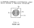
- FIG. 2 is a drawing showing the diffracted light which enters the two-piece detector, and it shows a state of the two-piece detector in FIG. 1 viewed from an upper surface (detecting surface).
- the two-piece detector 115 its two-piece detecting portions are provided in the right-and-left direction of FIG. 1 .
- Two lights (first-order diffracted lights D 1 ) which are diffracted by both edges of the groove, are diffracted in the right-and-left direction at a predetermined angle so that portions of the first-order diffracted lights D 1 enter the detecting portions on the right and left sides.
- a zero-order diffracted light D 0 enters the central portion of the two-piece detector 115 with it going over both of the detecting portions.
- Distribution of the light intensity occurs in an area where the zero-order and first-order diffracted lights D 0 and D 1 are overlapped (cross hatching section in FIG. 2) due to an interference effect caused by track shifting.
- the respective detecting portions detect the light intensity utilizing this distribution.
- the two-piece detector 115 converts the lights, which are inputted after divided into two, into current signals, and inputs them into current/voltage converting circuits 116 and 117 .
- the current/voltage converting circuits 116 and 117 respectively convert the inputted current signals into voltage signals so as to output them.
- the voltage signals outputted respectively from the current/voltage converting circuits 116 and 117 are amplified by amplifiers 118 and 119 , and a difference signal is generated in a differential amplifier 122 .
- the difference signal is outputted as a tracking error signal.
- the objective lens 114 is automatically tracked based on the tracking error signal and the seek is again carried out.
- FIG. 3 is a drawing showing an example of the ID section of the optical disk adopting the land/groove recording system suggested by the applicant of the present invention, and FIG. 3 shows a plan view (see Japanese Patent Application Laid-Open No. 10-79125 (1998)).
- the hatching section is a portion which is formed into a concave shape.
- information can be recorded in tracks formed by land portions 102 and groove portions 101 provided between the land portions 102 .
- Rows of prepits 104 and 103 which correspond to pre-format information of the adjacent land portion 102 and groove portion 101 , are formed with them being shifted in the circumferential direction.
- Count grooves 106 for counting tracks are formed on both sides of the rows of the prepits 104 for the land portions 102 , and through grooves 105 , which go through the rows of the prepits 103 for the groove portions 101 , are formed.
- FIG. 4 is a waveform chart showing TES (tracking error signal) obtained by the conventional optical recording medium driving apparatus.
- TES tracking error signal
- the present invention has been achieved in order to solve the above problem, and it is an object of the present invention to provide an optical recording medium driving apparatus which can obtain a tracking error signal necessary for an accurate track count.
- An optical recording medium driving apparatus for recording and/or reproducing data in/from an optical recording medium, where information can be recorded in plural tracks, based on a light emitted to the tracks of the optical recording medium, is constituted so as to have a detector for detecting a position of the emitted light, a peak-hold circuit for holding a peak of a position detected signal outputted from the detector so as to output the position detected signal, a bottom-hold circuit for outputting a bottom of the position detected signal so as to output the position detected signal, and a switching circuit for switching signals based on the output signals from the peak-hold circuit and bottom-hold circuit so as to output either signal.
- the optical recording medium driving apparatus is constituted so that the signal outputted from the switching circuit is used as a tracking error signal.
- the peak-hold circuit holds a peak of the signal outputted from the position detector so as to output the signal
- the bottom-hold circuit holds a bottom of the signal outputted from the position detector so as to output the signal.
- the switching circuit switches signals based on the output signals from the peak-hold circuit and bottom-hold circuit so as to output either signal, and the signal is used as a tracking error signal. As a result, a tracking error signal necessary for the accurate track count can be obtained.
- Another optical recording medium driving apparatus is constituted so that the switching circuit includes an absolute value circuit for outputting an absolute value of the signal based on the output signal from the peak-hold circuit, an absolute value circuit for outputting an absolute value of the signal based on the output signal. from the bottom-hold circuit, and a comparison circuit for comparing the absolute values outputted from the absolute value circuits so as to select either signal with the larger absolute value.
- the optical recording medium driving apparatus is constituted so that the switching circuit outputs the signal selected by the comparison circuit, and tracking servo and seek are carried out.
- the two absolute value circuits output respectively the absolute value of the signal based on the output signal from the peak-hold circuit and the absolute value of the signal based on the output signal from the bottom-hold circuit.
- the comparison circuit compares the absolute values outputted by the absolute value circuits, and the switching circuit outputs either signal with the larger absolute value.
- the ID is formed as a prepit on the extension of the land and on the extension of the groove.
- FIG. 5 is a waveform chart showing TES obtained by the optical recording medium driving apparatus according to the present invention.
- a dotted line in the drawing is a reproduction waveform when the light spot crosses not the ID section but the land/groove.
- amplitude of the signal 403 based on the output signal from the peak-hold circuit becomes larger than the other
- amplitude of the signal 405 based on the output signal from the bottom-hold circuit becomes larger than the other.
- the two-piece detector is used as the aforementioned position detector, and the two peak-hold circuits and two bottom-hold circuits hold peaks and bottoms of the two signals outputted from the two-piece detector so as to output the signals.
- the switching circuit switches the signals based on the output signals from the two peak-hold circuits and signals based on the output signals from the two bottom-hold circuits so as to output the signals. These signals can used as a tracking error signal.
- the optical recording medium driving apparatus can be constituted as follows. Namely, one absolute value circuit outputs an absolute value of the signal based on the difference signal of the output signals from the two peak-hold circuits, and the other absolute value circuit outputs an absolute value of the signal. based on the difference signal of the output signals from the two bottom-hold circuits.
- the comparison circuit compares the absolute values outputted from the absolute value circuits and outputs either signal with the larger absolute value.
- Still another optical recording medium driving apparatus for recording and/or reproducing data in/from an optical recording medium, where information can be recorded in plural tracks, based on a light emitted to the tracks of the optical recording medium, includes a detector for detecting positions of the emitted light, a peak-hold circuit for holding a peak of a difference signal of position detected signals outputted from the detector so as to output the difference signal, a bottom-hold circuit for holding a bottom of the difference signal so as to output the difference signal, and a switching circuit for switching the output signals from the peak-hold circuit and bottom-hold circuit so as to output either output signal.
- the optical recording medium driving apparatus is constituted so that the signal outputted from the switching circuit is used as a tracking error signal.
- the peak-hold circuit holds a peak of the difference signal of the position detected signals from the detector and outputs the difference signal
- the bottom-hold circuit holds a bottom of the difference signal of the position detected signals outputted from the detector and outputs the difference signal.
- the switching circuit switches the output signals from the peak-hold circuit and bottom-hold circuit and outputs either output signal, and the signal is used as a tracking error signal. As a result, a tracking error signal necessary for the accurate track count can be obtained.
- Still another optical recording medium driving apparatus is constituted so that the switching circuit includes an absolute value circuit for outputting an absolute value of the output signal from the peak-hold circuit, an absolute value circuit for outputting an absolute value of the output signal from the bottom-hold circuit, and a comparison circuit for comparing the absolute values outputted from the absolute value circuits so as to select either signal with the larger absolute value.
- the switching circuit outputs the signal with the larger absolute value selected by the comparison circuit.
- the two absolute value circuits output respectively absolute values of the output signals from the peak-hold circuit and bottom-hold circuit.
- the comparison circuit compares the absolute values outputted from the absolute value circuits and selects either signal with the larger absolute value, and the switching circuit outputs the selected signal.
- the output signal from the peak-hold circuit becomes a signal 403 whose fall due to a prepit of the ID section in the land portion was recovered
- the output signal from the bottom-hold circuit becomes a signal 405 whose fall due to the prepit of the ID section in the groove portion was recovered. Therefore, in the ID section of the land portion, amplitude of the output signal 403 from the peak-hold circuit becomes larger than the other, and in the ID section of the groove portion, amplitude of the output signal 405 from the bottom-hold circuit becomes larger than the other.
- Still another optical recording medium driving apparatus for recording and/or reproducing data in/from an optical recording medium, where information can be recorded in plural tracks, based on a light emitted to the tracks of the optical recording medium
- said driving apparatus is constituted so as to have a detector for detecting a position of the emitted light, and a low-pass filter for removing a frequency component generated due to prepits provided in the optical recording medium from a position detected signal outputted from the detector, and so that a signal based on an output from the low-pass filter is used as a tracking error signal.
- the low-pass filter filters the position detected signal outputted from the detector to remove high frequency component generated due to the prepit, and recovers the fall portions, where the frequency is comparatively high and which are generated in the ID sections of the land portion and groove portion, and the signal based on the output signal from the low-pass filter is used as a tracking error signal. Therefore, a tracking error signal necessary for the accurate track count can be obtained.
- Still another optical recording medium driving apparatus for recording and/or reproducing data in/from an optical recording medium, where information can be recorded in plural tracks, based on a light emitted to the tracks of the optical recording medium
- said driving apparatus is constituted so as to have a two-piece detector for detecting positions of the emitted light, and a low-pass filter for removing a frequency component due to prepits provided in the optical recording medium from position detected signals outputted by the two-piece detector, and so that a signal based on an output from the low-pass filter is used as a tracking error signal.
- the low-pass filter filters the difference signal of the position detected signals outputted from the two-piece detector to remove high frequency component generated due to the prepit, and recovers the fall portions, where the frequency is comparatively high and which are generated in the ID sections of the land portion and groove portion, and the signal based on the output from the low-pass filter is used as a tracking error signal. Therefore, a tracking error signal necessary for the accurate track count can be obtained.
- FIG. 1 is a block diagram showing a constitutional example of a conventional optical recording medium driving apparatus
- FIG. 2 is a drawing showing a diffracted light which enters a two-piece detector
- FIG. 3 is a drawing showing an example of an ID section of an optical disk
- FIG. 4 is a waveform chart showing TES obtained by the conventional optical recording medium driving apparatus
- FIG. 5 is a waveform chart showing TES obtained by an optical. recording medium driving apparatus according to the present invention.
- FIG. 6 is a block diagram showing a first embodiment of the optical recording medium driving apparatus according to the present invention.
- FIG. 7 is a block diagram showing a second embodiment of the optical recording medium driving apparatus according to the present invention.
- FIG. 8 is a block diagram showing a third embodiment of the optical recording medium driving apparatus according to the present invention.
- FIG. 9 is a block diagram showing a fourth embodiment of the optical recording medium driving apparatus according to the present invention.
- FIG. 6 is a block diagram showing a first embodiment of the optical recording medium driving apparatus according to the present invention.
- This driving apparatus optical recording medium driving apparatus
- This driving apparatus is schematically shown mainly a detecting part for a tracking error signal (TES).
- TES tracking error signal
- the light diffracted by a groove on the surface of the disk 110 passes through the objective lens 114 again. Then the light is reflected by the beam splitter 112 so that its optical path is bent, and the light enters a two-piece detector 115 .
- the two-piece detector 115 As shown in FIG. 2, its two-piece detecting portions are provided in the right-and-left direction of FIG. 1 .
- Two lights (first-order diffracted lights D 1 ), which are diffracted by both edges of the groove, are diffracted in the right-and-left direction at a predetermined angle so that portions of the first-order diffracted lights D 1 enter the detecting portions on the right and left sides.
- a zero-order diffracted light D 0 enters the central portion of the two-piece detector 115 with it going over both of the detecting portions.
- Distribution of the light intensity occurs in an area where the zero-order and first-order diffracted lights D 0 and D 1 are overlapped (cross hatching section in FIG. 2) due to an interference effect caused by track shifting.
- the respective detecting portions detect the light intensity utilizing this distribution.
- the two-piece detector 115 converts the lights, which were divided into two so as to be inputted, into current signals, and inputs them into current/voltage converting circuits 116 and 117 .
- the current/voltage converting circuits 116 and 117 respectively convert the inputted current signals into voltage signals so as to output them.
- the voltage signals outputted respectively from the current/voltage converting circuits 116 and 117 are amplified by amplifiers 118 and 119 .
- the voltage signal amplified by the amplifier 118 is given to a peak-hold circuit 311 and bottom-hold circuit 312 , and its peak and bottom are held so that the signals are outputted therefrom.
- the voltage signal amplified by the amplifier 119 is given to a peak-hold circuit 311 a and a bottom-hold circuit 312 a , and its peak and bottom are held so that the signals are outputted therefrom.
- the voltage signals which were outputted from the peak-hold circuits 311 and 311 a where their peak was held, are inputted into a differential amplifier 313 , and the differential amplifier 313 outputs a difference signal of the voltage signals so as to give the difference signal to a switching circuit 316 and absolute value circuit 314 .
- the voltage signals which were outputted from the bottom-hold circuits 312 and 312 a where their bottom was held, are inputted into a differential amplifier 313 a , and the differential amplifier 313 a outputs a difference signal of the voltage signals so as to give the difference signal to the switching circuit 316 and absolute value circuit 308 .
- the absolute values outputted by the absolute value circuits 308 and 314 are given to a comparison circuit 315 .
- the compared result of the comparison circuit 315 is given to the switching circuit 316 , and the switching circuit 316 outputs one of the difference signals outputted by the differential amplifiers 313 and 313 a , whose compared result of the comparison circuit 315 is larger than the other, as a tracking error signal.
- the objective lens 114 is automatically tracked based on the tracking error signal, and the seek is again carried out.
- information can be recorded in tracks formed by land portions 102 and groove portions 101 provided between the land portions 102 .
- Rows of prepits 104 and 103 which correspond to pre-format information of the adjacent land portion 102 and groove portion 101 , are formed with them being shifted in the circumferential direction.
- Count grooves 106 for counting tracks are formed on both sides of the rows of the prepits 104 for the land portions 102 , and through grooves 105 , which go through the rows of the prepits 103 for the groove portions 101 , are formed.
- a difference signal which was outputted by the differential amplifier 313 and is a signal based on the output signals from the peak-hold circuits 311 and 311 a , becomes, as shown in FIG. 5A, a signal 403 whose fall due to the prepit 104 of the ID section in the land portion was recovered (however, the fall 402 due to the through groove 105 of the ID section in the groove portion cannot be recovered).
- a difference signal which is the signal based on the output signals from the bottom-hold circuits 312 and 312 a and was outputted from the differential amplifier 313 a , becomes, as shown in FIG. 5B, a signal 405 whose fall due to the through groove 105 of the ID section in the groove portion was recovered (however, the fall 406 due to the prepit 104 of the ID section in the land portion cannot be recovered).
- amplitude of the signal ( 403 ) based on the output signals from the peak-hold circuits 311 and 311 a becomes larger than the other
- amplitude of the signal ( 405 ) based on output signals from the bottom-hold circuits 312 and 312 a becomes lager than the other.
- the switching circuit 315 selects either signal whose amplitude is lager than the other, namely, selects either signal whose fall was recovered. Therefore, a tracking error signal necessary for the accurate track count can be obtained.
- FIG. 7 is a block diagram showing a second embodiment of the optical recording medium driving apparatus according to the present invention.
- this driving apparatus optical recording medium driving apparatus
- voltage signals outputted from the current/voltage converting circuits 116 and 117 are amplified by the amplifiers 118 and 119 .
- the voltage signals amplified by the amplifiers 118 and 119 are inputted into a differential amplifier 508 , and the differential amplifier 508 outputs a difference signal of the voltage signals so as to give the difference signal to a peak-hold circuit 509 and bottom-hold circuit 510 .
- the voltage signal whose peak was held by the peak-hold circuit 509 and which was outputted, is given to a switching circuit 513 and absolute value circuit 511 .
- the voltage signal whose bottom was held by the bottom-hold circuit 510 and which was outputted, is given to the switching circuit 513 and absolute value circuit 505 .
- Absolute values outputted by the absolute value circuits 505 and 511 are given to a comparison circuit 512 .
- the compared result of the comparison circuit 512 is given to the switching circuit 513 , and the switching circuit 513 outputs the voltage signal, which was outputted by the peak-hold circuit 509 or bottom-hold circuit 510 and whose compared result of the comparison circuit 512 is lager than the other, as a tracking error signal.
- the objective lens 114 is automatically tracked based on this tracking error signal, and the seek is again carried out. Since the other parts of the constitution are the same as those of the aforementioned driving apparatus in FIG. 6, the description thereof is omitted.
- the output signal of the peak-hold circuit 509 becomes a signal 403 whose fall due to the prepit 104 of the ID section in the land portion was recovered (however, the fall 402 due to the through groove 105 of the ID section in the groove portion cannot be recovered).
- the output signal of the bottom-hold circuit 510 becomes a signal 405 whose fall due to the through groove 105 of the ID section in the groove portion was recovered (however, the fall 406 due to the prepit 104 of the ID section in the land portion cannot he recovered).
- amplitude of the output signal ( 403 ) from the peak-hold circuit becomes larger than the other
- amplitude of the output signal ( 405 ) from the bottom-hold circuit becomes larger than the other.
- the switching circuit 512 selects either signal whose amplitude is larger than the other, namely, selects either signal whose fall was recovered. Therefore, a tracking error signal necessary for the accurate track count can be obtained.
- FIG. 8 is a block diagram showing a third embodiment of the optical recording medium driving apparatus according to the present invention.
- this driving apparatus optical recording medium driving apparatus
- the voltage signals outputted from the current/voltage converting circuits 116 and 117 are amplified respectively by the amplifiers 118 and 119 .
- the voltage signals amplified by the amplifiers 118 and 119 are given respectively to filter circuits 520 and 521 (low-pass filters), which shut down a signal whose frequency component is higher than that of the tracking error signal when the optical heads moves at the maximum speed, and are filtered thereby.
- the voltage signals which were filtered respectively by the filter circuits 520 and 521 , are inputted into a differential amplifier 522 , and the differential amplifier 522 outputs a difference signal of the voltage signals as a tracking error signal.
- the objective lens 114 is automatically tracked based on the tracking error signal, and the seek is again carried out the other parts of constitution are the same as those of the aforementioned driving apparatus shown in FIG. 6, so the description thereof is omitted.
- the filter circuits 520 and 521 filter respectively the voltage signals amplified by the amplifiers 118 and 119 , and recovers the fall portions, where the frequency is comparatively higher and which are generated on the ID sections of the land portion and groove portion.
- the differential amplifier 522 outputs the difference signal of the recovered voltage signals as a tracking error signal. Therefore, a tracking error signal necessary for the accurate track count can be obtained.
- FIG. 9 is a block diagram showing a fourth embodiment of the optical recording medium driving apparatus according to the present invention.
- this driving apparatus optical recording medium driving apparatus
- the voltage signals amplified by the amplifiers 118 and 119 are inputted into a differential amplifier 523 , and the differential amplifier 523 outputs a difference signal of the voltage signals.
- the difference signal outputted by the differential amplifier 523 is given to a filter circuit 524 (low-pass filter), which shuts down a signal whose frequency is higher than that of the tracking error signal when the optical head moves at the maximum speed, and is filtered thereby so as to be outputted as a tracking error signal.
- the objective lens 114 is automatically tracked based on the tracking error signal, and the seek is again carried out.
- the other parts of the constitution are the same as those of the aforementioned driving apparatus shown in FIG. 6, so the description thereof is omitted.
- the voltage signals are amplified by the amplifiers 118 and 119 , and the difference signal of the voltage signals outputted from the differential amplifier 523 is filtered by the filter circuit 524 .
- the filter circuit 524 recovers fall portions, where the frequency is comparatively higher and which are generated in the ID sections of the land portion and groove portion, and outputs the tracking error signal. Therefore, a tracking error signal necessary for the accurate track count can be obtained.
- a tracking error signal necessary for an accurate track count can be obtained.
- amplitude of a signal based on an output signal from the peak-hold circuit becomes larger
- amplitude of a signal based on an output signal from the bottom-hold circuit becomes larger
- the low-pass filter filters a detected signal outputted from the detector, and recovers the fall portions, where the frequency is comparatively higher and which are generated in the ID sections of the land portion and groove portion. Since a signal based on the output from the low-pass filter is used as a tracking error signal, a tracking error signal necessary for the accurate track count can be obtained.
- the low-pass filter filters a difference signal of detected signals outputted from the two-piece detector and recovers fall portions, where the frequency is comparatively higher and which are generated in the ID sections of the land portion and groove portion. Since a signal based on the output from the low-pass filter is used as a tracking error signal, a tracking error signal necessary for the accurate track count can be obtained.
- the present invention can be applied also to a recording medium adopting the conventional land recording system and groove recording system, and thus the present invention has low-order compatibility.
Landscapes
- Optical Recording Or Reproduction (AREA)
- Moving Of The Head For Recording And Reproducing By Optical Means (AREA)
- Optical Record Carriers And Manufacture Thereof (AREA)
Applications Claiming Priority (3)
| Application Number | Priority Date | Filing Date | Title |
|---|---|---|---|
| JP9-287475 | 1997-10-20 | ||
| JP28747597A JP3753517B2 (ja) | 1997-10-20 | 1997-10-20 | 光記録媒体ドライブ装置 |
| PCT/JP1998/004743 WO1999021180A1 (fr) | 1997-10-20 | 1998-10-19 | Unite de support d'enregistrement optique |
Related Parent Applications (1)
| Application Number | Title | Priority Date | Filing Date |
|---|---|---|---|
| PCT/JP1998/004743 Continuation WO1999021180A1 (fr) | 1997-10-20 | 1998-10-19 | Unite de support d'enregistrement optique |
Publications (1)
| Publication Number | Publication Date |
|---|---|
| US6646961B1 true US6646961B1 (en) | 2003-11-11 |
Family
ID=17717829
Family Applications (1)
| Application Number | Title | Priority Date | Filing Date |
|---|---|---|---|
| US09/545,869 Expired - Fee Related US6646961B1 (en) | 1997-10-20 | 2000-04-06 | Optical recording medium driving apparatus |
Country Status (5)
| Country | Link |
|---|---|
| US (1) | US6646961B1 (ja) |
| EP (1) | EP1026673B1 (ja) |
| JP (1) | JP3753517B2 (ja) |
| DE (1) | DE69830419T2 (ja) |
| WO (1) | WO1999021180A1 (ja) |
Cited By (4)
| Publication number | Priority date | Publication date | Assignee | Title |
|---|---|---|---|---|
| US20040047250A1 (en) * | 2001-12-27 | 2004-03-11 | Koyu Yamanoi | Tracking error detector |
| US20060126466A1 (en) * | 2004-12-15 | 2006-06-15 | Seiji Imagawa | Information recording apparatus, information reproducing apparatus, information recording method, and information reproducing method with an improved track jump performance |
| US20070086296A1 (en) * | 2005-10-11 | 2007-04-19 | Hitachi-Lg Data Storage Korea, Inc. | Method for writing optical disc |
| US11077808B2 (en) * | 2017-02-14 | 2021-08-03 | Robert Bosch Gmbh | Circuit assemblage for carrying out a comparison |
Families Citing this family (1)
| Publication number | Priority date | Publication date | Assignee | Title |
|---|---|---|---|---|
| JP3615054B2 (ja) | 1998-06-04 | 2005-01-26 | ソニー株式会社 | 光学記録媒体 |
Citations (18)
| Publication number | Priority date | Publication date | Assignee | Title |
|---|---|---|---|---|
| JPS573232A (en) | 1980-06-06 | 1982-01-08 | Toshiba Corp | Detecting method for track on optical disk |
| JPS5891536A (ja) | 1981-11-25 | 1983-05-31 | Hitachi Ltd | デイジタル光デイスクのアクセス方式 |
| EP0080212A1 (en) | 1981-11-25 | 1983-06-01 | Hitachi, Ltd. | Optical memory apparatus |
| JPS58169370A (ja) | 1982-03-30 | 1983-10-05 | Hitachi Ltd | 光デイスク装置 |
| US4504937A (en) | 1982-01-06 | 1985-03-12 | Hitachi, Ltd. | Optical information tracking apparatus |
| KR880000999A (ko) | 1986-06-25 | 1988-03-30 | 챨스 데이비스 | 소형 전자 소자 취급용 장치와 컴플라이언트 부재 및 모판 골격 |
| JPS63122024A (ja) | 1986-11-12 | 1988-05-26 | Nec Corp | トラツククロスパルス発生器 |
| EP0305979A2 (en) | 1987-09-04 | 1989-03-08 | Hitachi, Ltd. | Optical recording and reproducing system using optical recording medium |
| EP0320975A2 (en) | 1987-12-18 | 1989-06-21 | Hitachi, Ltd. | Information recording/reproducing method and apparatus |
| JPH01169742A (ja) | 1987-12-24 | 1989-07-05 | Nec Corp | トラック極性検出装置 |
| US5130967A (en) * | 1989-05-01 | 1992-07-14 | Pioneer Electronic Corporation | On/off-track detecting apparatus for compatible disk player |
| US5181195A (en) * | 1990-05-18 | 1993-01-19 | Sony Corporation | Tracking error signal generator with dc offset cancellation |
| EP0752701A2 (en) | 1995-07-07 | 1997-01-08 | Matsushita Electric Industrial Co., Ltd. | An optical information recording medium and an optical information recording/reproducing device |
| EP0779613A2 (en) | 1995-12-15 | 1997-06-18 | Fujitsu Limited | Optical disk apparatus |
| JPH1079125A (ja) | 1996-08-30 | 1998-03-24 | Fujitsu Ltd | 光記録媒体及びドライブ装置 |
| JPH10269593A (ja) | 1997-03-25 | 1998-10-09 | Hitachi Ltd | 光スポット位置制御装置 |
| US5896354A (en) * | 1996-04-22 | 1999-04-20 | Fujitsu Limited | Optical storage apparatus having switching control circuit for controlling an envelope detecting function in accordance with a medium type or access type |
| US5926445A (en) * | 1995-12-22 | 1999-07-20 | Pioneer Electronic Corporation | Waveform controlling device for a tracking error signal |
-
1997
- 1997-10-20 JP JP28747597A patent/JP3753517B2/ja not_active Expired - Fee Related
-
1998
- 1998-10-19 EP EP98947958A patent/EP1026673B1/en not_active Expired - Lifetime
- 1998-10-19 WO PCT/JP1998/004743 patent/WO1999021180A1/ja active IP Right Grant
- 1998-10-19 DE DE69830419T patent/DE69830419T2/de not_active Expired - Fee Related
-
2000
- 2000-04-06 US US09/545,869 patent/US6646961B1/en not_active Expired - Fee Related
Patent Citations (21)
| Publication number | Priority date | Publication date | Assignee | Title |
|---|---|---|---|---|
| JPS573232A (en) | 1980-06-06 | 1982-01-08 | Toshiba Corp | Detecting method for track on optical disk |
| JPS5891536A (ja) | 1981-11-25 | 1983-05-31 | Hitachi Ltd | デイジタル光デイスクのアクセス方式 |
| EP0080212A1 (en) | 1981-11-25 | 1983-06-01 | Hitachi, Ltd. | Optical memory apparatus |
| EP0141396A2 (en) | 1981-11-25 | 1985-05-15 | Hitachi, Ltd. | Access device for positioning a light beam to a desired guide groove of an optical memory apparatus |
| US4607358A (en) | 1981-11-25 | 1986-08-19 | Hitachi, Ltd. | Optical memory apparatus |
| US4504937A (en) | 1982-01-06 | 1985-03-12 | Hitachi, Ltd. | Optical information tracking apparatus |
| JPS58169370A (ja) | 1982-03-30 | 1983-10-05 | Hitachi Ltd | 光デイスク装置 |
| KR880000999A (ko) | 1986-06-25 | 1988-03-30 | 챨스 데이비스 | 소형 전자 소자 취급용 장치와 컴플라이언트 부재 및 모판 골격 |
| JPS63122024A (ja) | 1986-11-12 | 1988-05-26 | Nec Corp | トラツククロスパルス発生器 |
| EP0305979A2 (en) | 1987-09-04 | 1989-03-08 | Hitachi, Ltd. | Optical recording and reproducing system using optical recording medium |
| EP0320975A2 (en) | 1987-12-18 | 1989-06-21 | Hitachi, Ltd. | Information recording/reproducing method and apparatus |
| JPH01169742A (ja) | 1987-12-24 | 1989-07-05 | Nec Corp | トラック極性検出装置 |
| US5130967A (en) * | 1989-05-01 | 1992-07-14 | Pioneer Electronic Corporation | On/off-track detecting apparatus for compatible disk player |
| US5181195A (en) * | 1990-05-18 | 1993-01-19 | Sony Corporation | Tracking error signal generator with dc offset cancellation |
| EP0752701A2 (en) | 1995-07-07 | 1997-01-08 | Matsushita Electric Industrial Co., Ltd. | An optical information recording medium and an optical information recording/reproducing device |
| EP0779613A2 (en) | 1995-12-15 | 1997-06-18 | Fujitsu Limited | Optical disk apparatus |
| US5926445A (en) * | 1995-12-22 | 1999-07-20 | Pioneer Electronic Corporation | Waveform controlling device for a tracking error signal |
| US5896354A (en) * | 1996-04-22 | 1999-04-20 | Fujitsu Limited | Optical storage apparatus having switching control circuit for controlling an envelope detecting function in accordance with a medium type or access type |
| JPH1079125A (ja) | 1996-08-30 | 1998-03-24 | Fujitsu Ltd | 光記録媒体及びドライブ装置 |
| US5978327A (en) | 1996-08-30 | 1999-11-02 | Fujitsu Limited | Optical recording medium for land-and-groove recording system |
| JPH10269593A (ja) | 1997-03-25 | 1998-10-09 | Hitachi Ltd | 光スポット位置制御装置 |
Cited By (6)
| Publication number | Priority date | Publication date | Assignee | Title |
|---|---|---|---|---|
| US20040047250A1 (en) * | 2001-12-27 | 2004-03-11 | Koyu Yamanoi | Tracking error detector |
| US7126889B2 (en) * | 2001-12-27 | 2006-10-24 | Texas Instruments Incorporated | Tracking error detector |
| US20060126466A1 (en) * | 2004-12-15 | 2006-06-15 | Seiji Imagawa | Information recording apparatus, information reproducing apparatus, information recording method, and information reproducing method with an improved track jump performance |
| US20070086296A1 (en) * | 2005-10-11 | 2007-04-19 | Hitachi-Lg Data Storage Korea, Inc. | Method for writing optical disc |
| US7916597B2 (en) * | 2005-10-11 | 2011-03-29 | Hitachi-Lg Data Storage Korea, Inc. | Method for writing optical disc |
| US11077808B2 (en) * | 2017-02-14 | 2021-08-03 | Robert Bosch Gmbh | Circuit assemblage for carrying out a comparison |
Also Published As
| Publication number | Publication date |
|---|---|
| EP1026673B1 (en) | 2005-06-01 |
| EP1026673A1 (en) | 2000-08-09 |
| WO1999021180A1 (fr) | 1999-04-29 |
| DE69830419T2 (de) | 2005-11-10 |
| JPH11126343A (ja) | 1999-05-11 |
| EP1026673A4 (en) | 2001-01-31 |
| JP3753517B2 (ja) | 2006-03-08 |
| DE69830419D1 (de) | 2005-07-07 |
Similar Documents
| Publication | Publication Date | Title |
|---|---|---|
| US4787075A (en) | Optical information recording medium and apparatus for recording/reproducing information using the same | |
| EP0987687A2 (en) | Optical disk and optical disk device | |
| MXPA05002568A (es) | Medio de almacenamiento de informacion optica. | |
| US6646961B1 (en) | Optical recording medium driving apparatus | |
| JPH0916986A (ja) | 光ディスク装置 | |
| EP0573021B1 (en) | Reproducing system for an optical disc | |
| KR20080021120A (ko) | 3 스폿 반경방향 트랙킹을 하는 광학계 | |
| US6567368B1 (en) | Optical recording medium and method and apparatus of reproducing the same | |
| KR100565044B1 (ko) | 워블된 랜드 트랙과는 이위상의 워블된 그루브 트랙을 갖는 기록매체, 워블신호를 이용하는 서보제어장치 및 그 방법 | |
| KR100265237B1 (ko) | 쉘로우/딥-그루브 방식 광디스크의 트래킹 방법 및 그 장치 | |
| EP1043714B1 (en) | Optical recording medium | |
| JPH0582659B2 (ja) | ||
| WO2004081928A1 (ja) | 光ディスク | |
| JP2776459B2 (ja) | 光ディスク | |
| JPH07110956A (ja) | 円盤状記録媒体の記録再生装置 | |
| JP4065623B2 (ja) | ディスク装置 | |
| JP3120932B2 (ja) | 光学的情報装置 | |
| RU2321081C2 (ru) | Устройство регулирования фокуса | |
| JP2865087B2 (ja) | ランドグルーブ位置検出方式及び方法 | |
| JPS61153834A (ja) | 光学的情報記録再生装置 | |
| KR100713545B1 (ko) | 광디스크의 트래킹 방법 및 장치 | |
| KR100200856B1 (ko) | 광픽업의 구동 알고리즘 | |
| JP2005092992A (ja) | 光ディスク装置 | |
| KR20070049086A (ko) | 트랙킹 에러 검출 방법, 트랙킹 에러 검출 장치 및광기록재생장치 | |
| JPH1116174A (ja) | 光ディスク装置 |
Legal Events
| Date | Code | Title | Description |
|---|---|---|---|
| AS | Assignment |
Owner name: FUJITSU LIMITED, JAPAN Free format text: ASSIGNMENT OF ASSIGNORS INTEREST;ASSIGNORS:IIDA, KOICHI;KURODA, SUMIO;REEL/FRAME:010700/0892 Effective date: 20000308 |
|
| FEPP | Fee payment procedure |
Free format text: PAYOR NUMBER ASSIGNED (ORIGINAL EVENT CODE: ASPN); ENTITY STATUS OF PATENT OWNER: LARGE ENTITY |
|
| FPAY | Fee payment |
Year of fee payment: 4 |
|
| AS | Assignment |
Owner name: MATSUSHITA ELECTRIC INDUSTRIAL CO., LTD., JAPAN Free format text: ASSIGNMENT OF ASSIGNORS INTEREST;ASSIGNOR:FUJITSU LIMITED;REEL/FRAME:021147/0661 Effective date: 20080305 |
|
| REMI | Maintenance fee reminder mailed | ||
| LAPS | Lapse for failure to pay maintenance fees | ||
| STCH | Information on status: patent discontinuation |
Free format text: PATENT EXPIRED DUE TO NONPAYMENT OF MAINTENANCE FEES UNDER 37 CFR 1.362 |
|
| FP | Lapsed due to failure to pay maintenance fee |
Effective date: 20111111 |