EP0987687A2 - Optical disk and optical disk device - Google Patents
Optical disk and optical disk device Download PDFInfo
- Publication number
- EP0987687A2 EP0987687A2 EP99250329A EP99250329A EP0987687A2 EP 0987687 A2 EP0987687 A2 EP 0987687A2 EP 99250329 A EP99250329 A EP 99250329A EP 99250329 A EP99250329 A EP 99250329A EP 0987687 A2 EP0987687 A2 EP 0987687A2
- Authority
- EP
- European Patent Office
- Prior art keywords
- region
- signal
- optical disk
- pit
- recording
- Prior art date
- Legal status (The legal status is an assumption and is not a legal conclusion. Google has not performed a legal analysis and makes no representation as to the accuracy of the status listed.)
- Withdrawn
Links
Images


Classifications
-
- G—PHYSICS
- G11—INFORMATION STORAGE
- G11B—INFORMATION STORAGE BASED ON RELATIVE MOVEMENT BETWEEN RECORD CARRIER AND TRANSDUCER
- G11B7/00—Recording or reproducing by optical means, e.g. recording using a thermal beam of optical radiation by modifying optical properties or the physical structure, reproducing using an optical beam at lower power by sensing optical properties; Record carriers therefor
- G11B7/24—Record carriers characterised by shape, structure or physical properties, or by the selection of the material
- G11B7/2407—Tracks or pits; Shape, structure or physical properties thereof
- G11B7/24085—Pits
-
- G—PHYSICS
- G11—INFORMATION STORAGE
- G11B—INFORMATION STORAGE BASED ON RELATIVE MOVEMENT BETWEEN RECORD CARRIER AND TRANSDUCER
- G11B20/00—Signal processing not specific to the method of recording or reproducing; Circuits therefor
- G11B20/10—Digital recording or reproducing
- G11B20/12—Formatting, e.g. arrangement of data block or words on the record carriers
- G11B20/1217—Formatting, e.g. arrangement of data block or words on the record carriers on discs
-
- G—PHYSICS
- G11—INFORMATION STORAGE
- G11B—INFORMATION STORAGE BASED ON RELATIVE MOVEMENT BETWEEN RECORD CARRIER AND TRANSDUCER
- G11B27/00—Editing; Indexing; Addressing; Timing or synchronising; Monitoring; Measuring tape travel
- G11B27/10—Indexing; Addressing; Timing or synchronising; Measuring tape travel
- G11B27/19—Indexing; Addressing; Timing or synchronising; Measuring tape travel by using information detectable on the record carrier
-
- G—PHYSICS
- G11—INFORMATION STORAGE
- G11B—INFORMATION STORAGE BASED ON RELATIVE MOVEMENT BETWEEN RECORD CARRIER AND TRANSDUCER
- G11B7/00—Recording or reproducing by optical means, e.g. recording using a thermal beam of optical radiation by modifying optical properties or the physical structure, reproducing using an optical beam at lower power by sensing optical properties; Record carriers therefor
- G11B7/007—Arrangement of the information on the record carrier, e.g. form of tracks, actual track shape, e.g. wobbled, or cross-section, e.g. v-shaped; Sequential information structures, e.g. sectoring or header formats within a track
- G11B7/00718—Groove and land recording, i.e. user data recorded both in the grooves and on the lands
-
- G—PHYSICS
- G11—INFORMATION STORAGE
- G11B—INFORMATION STORAGE BASED ON RELATIVE MOVEMENT BETWEEN RECORD CARRIER AND TRANSDUCER
- G11B7/00—Recording or reproducing by optical means, e.g. recording using a thermal beam of optical radiation by modifying optical properties or the physical structure, reproducing using an optical beam at lower power by sensing optical properties; Record carriers therefor
- G11B7/007—Arrangement of the information on the record carrier, e.g. form of tracks, actual track shape, e.g. wobbled, or cross-section, e.g. v-shaped; Sequential information structures, e.g. sectoring or header formats within a track
- G11B7/00745—Sectoring or header formats within a track
-
- G—PHYSICS
- G11—INFORMATION STORAGE
- G11B—INFORMATION STORAGE BASED ON RELATIVE MOVEMENT BETWEEN RECORD CARRIER AND TRANSDUCER
- G11B7/00—Recording or reproducing by optical means, e.g. recording using a thermal beam of optical radiation by modifying optical properties or the physical structure, reproducing using an optical beam at lower power by sensing optical properties; Record carriers therefor
- G11B7/08—Disposition or mounting of heads or light sources relatively to record carriers
- G11B7/09—Disposition or mounting of heads or light sources relatively to record carriers with provision for moving the light beam or focus plane for the purpose of maintaining alignment of the light beam relative to the record carrier during transducing operation, e.g. to compensate for surface irregularities of the latter or for track following
- G11B7/0938—Disposition or mounting of heads or light sources relatively to record carriers with provision for moving the light beam or focus plane for the purpose of maintaining alignment of the light beam relative to the record carrier during transducing operation, e.g. to compensate for surface irregularities of the latter or for track following servo format, e.g. guide tracks, pilot signals
-
- G—PHYSICS
- G11—INFORMATION STORAGE
- G11B—INFORMATION STORAGE BASED ON RELATIVE MOVEMENT BETWEEN RECORD CARRIER AND TRANSDUCER
- G11B7/00—Recording or reproducing by optical means, e.g. recording using a thermal beam of optical radiation by modifying optical properties or the physical structure, reproducing using an optical beam at lower power by sensing optical properties; Record carriers therefor
- G11B7/08—Disposition or mounting of heads or light sources relatively to record carriers
- G11B7/09—Disposition or mounting of heads or light sources relatively to record carriers with provision for moving the light beam or focus plane for the purpose of maintaining alignment of the light beam relative to the record carrier during transducing operation, e.g. to compensate for surface irregularities of the latter or for track following
- G11B7/094—Methods and circuits for servo offset compensation
-
- G—PHYSICS
- G11—INFORMATION STORAGE
- G11B—INFORMATION STORAGE BASED ON RELATIVE MOVEMENT BETWEEN RECORD CARRIER AND TRANSDUCER
- G11B7/00—Recording or reproducing by optical means, e.g. recording using a thermal beam of optical radiation by modifying optical properties or the physical structure, reproducing using an optical beam at lower power by sensing optical properties; Record carriers therefor
- G11B7/08—Disposition or mounting of heads or light sources relatively to record carriers
- G11B7/09—Disposition or mounting of heads or light sources relatively to record carriers with provision for moving the light beam or focus plane for the purpose of maintaining alignment of the light beam relative to the record carrier during transducing operation, e.g. to compensate for surface irregularities of the latter or for track following
- G11B7/0948—Disposition or mounting of heads or light sources relatively to record carriers with provision for moving the light beam or focus plane for the purpose of maintaining alignment of the light beam relative to the record carrier during transducing operation, e.g. to compensate for surface irregularities of the latter or for track following specially adapted for detection and avoidance or compensation of imperfections on the carrier, e.g. dust, scratches, dropouts
-
- G—PHYSICS
- G11—INFORMATION STORAGE
- G11B—INFORMATION STORAGE BASED ON RELATIVE MOVEMENT BETWEEN RECORD CARRIER AND TRANSDUCER
- G11B11/00—Recording on or reproducing from the same record carrier wherein for these two operations the methods are covered by different main groups of groups G11B3/00 - G11B7/00 or by different subgroups of group G11B9/00; Record carriers therefor
- G11B11/10—Recording on or reproducing from the same record carrier wherein for these two operations the methods are covered by different main groups of groups G11B3/00 - G11B7/00 or by different subgroups of group G11B9/00; Record carriers therefor using recording by magnetic means or other means for magnetisation or demagnetisation of a record carrier, e.g. light induced spin magnetisation; Demagnetisation by thermal or stress means in the presence or not of an orienting magnetic field
- G11B11/105—Recording on or reproducing from the same record carrier wherein for these two operations the methods are covered by different main groups of groups G11B3/00 - G11B7/00 or by different subgroups of group G11B9/00; Record carriers therefor using recording by magnetic means or other means for magnetisation or demagnetisation of a record carrier, e.g. light induced spin magnetisation; Demagnetisation by thermal or stress means in the presence or not of an orienting magnetic field using a beam of light or a magnetic field for recording by change of magnetisation and a beam of light for reproducing, i.e. magneto-optical, e.g. light-induced thermomagnetic recording, spin magnetisation recording, Kerr or Faraday effect reproducing
- G11B11/1055—Disposition or mounting of transducers relative to record carriers
- G11B11/10576—Disposition or mounting of transducers relative to record carriers with provision for moving the transducers for maintaining alignment or spacing relative to the carrier
-
- G—PHYSICS
- G11—INFORMATION STORAGE
- G11B—INFORMATION STORAGE BASED ON RELATIVE MOVEMENT BETWEEN RECORD CARRIER AND TRANSDUCER
- G11B20/00—Signal processing not specific to the method of recording or reproducing; Circuits therefor
- G11B20/10—Digital recording or reproducing
- G11B20/12—Formatting, e.g. arrangement of data block or words on the record carriers
- G11B20/1217—Formatting, e.g. arrangement of data block or words on the record carriers on discs
- G11B2020/1218—Formatting, e.g. arrangement of data block or words on the record carriers on discs wherein the formatting concerns a specific area of the disc
- G11B2020/1232—Formatting, e.g. arrangement of data block or words on the record carriers on discs wherein the formatting concerns a specific area of the disc sector, i.e. the minimal addressable physical data unit
-
- G—PHYSICS
- G11—INFORMATION STORAGE
- G11B—INFORMATION STORAGE BASED ON RELATIVE MOVEMENT BETWEEN RECORD CARRIER AND TRANSDUCER
- G11B20/00—Signal processing not specific to the method of recording or reproducing; Circuits therefor
- G11B20/10—Digital recording or reproducing
- G11B20/12—Formatting, e.g. arrangement of data block or words on the record carriers
- G11B2020/1264—Formatting, e.g. arrangement of data block or words on the record carriers wherein the formatting concerns a specific kind of data
- G11B2020/1265—Control data, system data or management information, i.e. data used to access or process user data
- G11B2020/1267—Address data
- G11B2020/1274—Address data stored in pre-pits, i.e. in embossed pits, ROM marks or prepits
-
- G—PHYSICS
- G11—INFORMATION STORAGE
- G11B—INFORMATION STORAGE BASED ON RELATIVE MOVEMENT BETWEEN RECORD CARRIER AND TRANSDUCER
- G11B20/00—Signal processing not specific to the method of recording or reproducing; Circuits therefor
- G11B20/10—Digital recording or reproducing
- G11B20/12—Formatting, e.g. arrangement of data block or words on the record carriers
- G11B2020/1264—Formatting, e.g. arrangement of data block or words on the record carriers wherein the formatting concerns a specific kind of data
- G11B2020/1265—Control data, system data or management information, i.e. data used to access or process user data
- G11B2020/1287—Synchronisation pattern, e.g. VCO fields
-
- G—PHYSICS
- G11—INFORMATION STORAGE
- G11B—INFORMATION STORAGE BASED ON RELATIVE MOVEMENT BETWEEN RECORD CARRIER AND TRANSDUCER
- G11B20/00—Signal processing not specific to the method of recording or reproducing; Circuits therefor
- G11B20/10—Digital recording or reproducing
- G11B20/12—Formatting, e.g. arrangement of data block or words on the record carriers
- G11B2020/1291—Formatting, e.g. arrangement of data block or words on the record carriers wherein the formatting serves a specific purpose
- G11B2020/1298—Enhancement of the signal quality
-
- G—PHYSICS
- G11—INFORMATION STORAGE
- G11B—INFORMATION STORAGE BASED ON RELATIVE MOVEMENT BETWEEN RECORD CARRIER AND TRANSDUCER
- G11B2220/00—Record carriers by type
- G11B2220/20—Disc-shaped record carriers
- G11B2220/21—Disc-shaped record carriers characterised in that the disc is of read-only, rewritable, or recordable type
- G11B2220/215—Recordable discs
- G11B2220/216—Rewritable discs
-
- G—PHYSICS
- G11—INFORMATION STORAGE
- G11B—INFORMATION STORAGE BASED ON RELATIVE MOVEMENT BETWEEN RECORD CARRIER AND TRANSDUCER
- G11B2220/00—Record carriers by type
- G11B2220/20—Disc-shaped record carriers
- G11B2220/25—Disc-shaped record carriers characterised in that the disc is based on a specific recording technology
- G11B2220/2537—Optical discs
-
- G—PHYSICS
- G11—INFORMATION STORAGE
- G11B—INFORMATION STORAGE BASED ON RELATIVE MOVEMENT BETWEEN RECORD CARRIER AND TRANSDUCER
- G11B27/00—Editing; Indexing; Addressing; Timing or synchronising; Monitoring; Measuring tape travel
- G11B27/10—Indexing; Addressing; Timing or synchronising; Measuring tape travel
- G11B27/19—Indexing; Addressing; Timing or synchronising; Measuring tape travel by using information detectable on the record carrier
- G11B27/28—Indexing; Addressing; Timing or synchronising; Measuring tape travel by using information detectable on the record carrier by using information signals recorded by the same method as the main recording
- G11B27/30—Indexing; Addressing; Timing or synchronising; Measuring tape travel by using information detectable on the record carrier by using information signals recorded by the same method as the main recording on the same track as the main recording
- G11B27/3027—Indexing; Addressing; Timing or synchronising; Measuring tape travel by using information detectable on the record carrier by using information signals recorded by the same method as the main recording on the same track as the main recording used signal is digitally coded
Definitions
- This invention relates to a disk format on optical disk, and to an optical disk device that can conduct the recording and playback of such an optical disk.
- a land/groove recording system that a region between grooves is also used as an information track, as well as a groove provided as a guide trench on optical disk has been suggested.
- the land and groove may be called convex part and concave part, respectively, or called inter-groove part and groove part, respectively.
- FIG.1 is a partial enlarged plan view showing a conventional optical disk that is described in Japanese patent No.2,663,817.
- G indicates a groove region
- L indicates a land region
- Tp indicates a track pitch
- P indicates a pre-pit
- BS indicates a focused beam spot.
- identification signal region in Japanese patent No.2, 663,817 is called “header region” herein.
- a header region including address information is shared between adjacent groove G and land L, and at least a part of information signal included in header region is shifted by Tp/4 to the center line of groove G and to the center line of land L, and in at least part of optical disk, the header region and recording data region each are formed in a radial pattern.
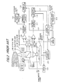
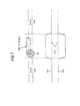
- FIG.2 is a block diagram showing the composition of an optical disk device used for the optical disk above.
- 100 is the optical disk
- 103 is a half mirror serving as a beam splitter
- 104 is an objective lens to converge collimated light passed through the half mirror 103 onto the optical disk 100
- 105 is a collimator lens to collimate light from a semiconductor laser 106
- 108 is an optical detector to receive reflected light from the optical disk 100 passing though the objective lens 104 and the half mirror 103.
- the optical detector is composed of two light-receiving parts that are divided in parallel to the track direction (tangential direction of circumference) of the optical disk to obtain the tracking error signal.
- 102 is an actuator supporting the objective lens 104.
- part 101 enclosed by a dotted line in FIG.2 is attached to a head base (not shown), and compose an optical head.
- 110 is a differential amplifier to which a detection signal to be output from the optical detector 108 is input.
- 117 is a polarity inverter to which a tracking error signal from the differential amplifier 110 and a control signal L4 from a system controller 11B described later are input, and which controls the polarity of tracking error signal output to a tracking controller 116 according to the control signal L4.
- the polarity of tracking control when tracking error signal is input, with its polarity unaltered, from the differential amplifier 110 to the tracking controller 116, the tracking is pulled into the recording track of groove G.
- 116 is the tracking controller to which an output signal from the polarity inverter, 117 and a control signal L1 from the system controller 118 are input, and which outputs tracking control signal to a driver 122 and a traverse controller 121
- 109 is an adder amplifier to which detection signal output from the optical detector 108 is input and which outputs an add signal.
- 112 is a waveform shaper to which an RF component from the adder amplifier is input, and which outputs a digital signal to a playback signal processor 113 and a address playback circuit 114.
- 113 is the playback signal processor which outputs playback data to the output terminal.
- 114 is the address playback circuit to which digital signal from the waveform shaper 112 is input, and which outputs an address signal.
- 115 is an address calculator to which address signal from the address playback circuit 114 and control signal L4 from the system controller 118 are input, and which outputs address signal to the system controller 118.
- 121 is the traverse controller which outputs drive current according to control signal from the system controller 118.
- 107 is a traverse motor which moves the optical head 101 in the radius direction of the optical disk 100 according to drive current from the traverse controller 121.
- 119 is a record signal processor to which record data is input and which outputs record signal to a laser (LD) driver 120.
- 120 is the LD driver to which control signal from the system controller 118 and record signal from the record signal processor 119 are input, and which supplies drive current to the semiconductor laser 106.
- 122 is the driver to which tracking control signal from the tracking controller 116 is input and which supplies drive current to the actuator 102.
- system controller 118 which outputs control signal L1, L4 to the tracking controller 116, the traverse controller 121, the address calculator 115, the polarity inverter 117, the record signal processor 119 and the LD driver 120, and to which address signal from the address calculator 115 is input.
- Light output from the semiconductor laser 106 is collimated by the collimator lens 105, passed through the beam splitter 103, converged onto the optical disk 100 by the objective lens 104.
- Laser light reflected on the optical disk 100 holds the information of record track, passing through the objective lens 104, being led through the beam splitter 103 to the optical detector 108.
- the optical detector 108 converts a variation in light quantity distribution of light beam supplied into electrical signal, outputting it to the differential amplifier 110, the adder amplifier 109.
- the differential amplifier 110 current-voltage-converts (I-V conversion) currents input, taking the difference of both voltages, outputting it as push-pull signal.
- the polarity inverter 117 judges whether the track accessed is a land or a groove according to control signal L4 from the system controller 118, inverting the polarity, for example, only when the track is a land.
- the tracking controller 116 outputs tracking control signal to the driver 122 according to the level of tracking error signal input, the driver 122 supplies current to the actuator according to this signal to control the position of the objective lens 104 in the radius direction across the recording track. Thereby, the optical spot can scan precisely on the track.
- the adder amplifier 109 current-voltage-converts (I-V conversion) two currents output from the light-receiving part 108, adding both, outputting it as add signal to the waveform shaper 112.
- the waveform shaper 112 shapes data signal and address signal with an analogue waveform into a pulse waveform by data-slicing by a certain threshold value, outputting it to the playback signal processor 113 and the address playback circuit 114.
- the playback signal processor 113 demodulates digital data signal input, conducting the processing of error correction etc. to output it as playback data.
- the address playback circuit 114 demodulates digital address signal input, outputting it as position information on the disk to the address calculator 115.
- the address calculator 115 calculates the address of a sector accessed from address signal read out from the optical disk 100 and land/groove signal from the system controller 118. The calculation method is to judge referring to an address map etc. and then output the judgement signal.
- the system controller 118 judges whether the light beam currently locates at a desired address based on this address signal.
- the traverse controller 121 outputs drive current to the traverse motor 107 according to control signal from the system controller 118 when shifting the optical head 101, thereby the optical head 101 is shifted to a target track.
- the tracking controller 116 suspends the tracking servo according to control signal L1 from the system controller 118.
- the traverse motor 107 is driven according to tracking error signal input from the tracking controller 116, and the optical head 101 is moved gradually in the radius direction as the playback operation proceeds.
- the record signal processor 119 adds an error correction code etc. to record data input, outputting it as encoded record data to the LD driver 120.
- the LD driver 120 modulates drive current applied to the semiconductor laser 106 according to record signal. Thereby, the intensity of light spots projected onto the optical disk 100 varies according to the record signal, record pits are formed.
- the LD driver 120 is set to the playback mode by control signal, the drive current is controlled so that the semiconductor laser 106 emits light at a constant intensity. Thereby, the detection of record pit and pre-pit on record track is enabled.
- Japanese patent No.2, 663,817 discloses not only a technique that the detection of record pit and pre-pit is conducted using track add signal but also a way to detect a pre-pit using push-pull signal which is track difference signal. Namely, since the header region is positioned offsetting by Tp/4 from the record track in the radius direction, the detection using push-pull signal is enabled.
- the optical disk and optical disk device using the land region and groove region as an information track have a significant weakness for the defocusing of focused beam. Namely, due to an error in the manufacturing of head or a deterioration in head performance with age, so-called defocusing that focused beam is converged deviating from a right focus position occurs.
- information of adjacent header regions affects as a crosstalk.
- one address information is a signal of short mark and other to crosstalk is a signal of long mark
- a significant distortion of waveform is observed and an error in the reading of address information occurs.
- the header region needs to be played back while waiting for the rotation, the throughput may be reduced. Also, when it is played back again, the reading error is highly like to recur. Therefore, since it may be registered as a defect sector, the reliability of device and disk must be thus reduced.
- the system controller judges whether the designated address is the land region or groove region by referring to an address map etc. Then, judgement signal (polarity signal) is output to the tracking servo system. After the tracking, detection signal of the physical address is address-converted by the judgement signal, thereby it is judged whether the tracking is carried out to the designated address.
- judgement signal polarity signal
- detection signal of the physical address is address-converted by the judgement signal, thereby it is judged whether the tracking is carried out to the designated address.
- the judgement of address becomes unsuccessful and the operation of the device goes out of control.
- the influence of the pre-pit to servo error signal is to cause the focus offset and the disorder of track error signal, thereby incurring a unstable recording/playback.
- the focus offset due to the chromatic aberration of an objective lens, by a phenomenon called a jump of wavelength in semiconductor laser. This focus offset interferes with the focus offset occurring near the header region, thereby the focus control is made to be further unstable, causing a failure in recording.
- an optical disk comprises:
- an optical disk device for conducting the recording/playback of an optical disk comprising a land region and a groove region that are formed on a substrate, the land region and groove region being used as a recording track that is the medium of the recording/playback of information signal, and a pre-pit region that is formed at the boundary part of neighboring land region and groove region and is disposed every other boundary part, the pre-pit region including address information, comprises:
- an optical disk device for conducting the recording/playback of an optical disk comprising a land region and a groove region that are formed on a substrate, the land region and groove region being used as a recording track that is the medium of the recording/playback of information signal, and a pre-pit region that is formed at the boundary part of neighboring land region and groove region and is disposed every other boundary part, the pre-pit region including address information, comprises:
- an optical disk device for conducting the recording/playback of an optical disk comprising a land region and a groove region that are formed on a substrate, the land region and groove region being used as a recording track that is the medium of the recording/playback of information signal, and a pre-pit region that is formed at the boundary part of neighboring land region and groove region and is disposed every other boundary part, the pre-pit region including address information, comprises:
- an optical disk device for conducting the recording/playback of an optical disk comprising a land region and a groove region that are formed on a substrate, the land region and groove region being used as a recording track that is the medium of the recording/playback of information signal, and a pre-pit region that is formed at the boundary part of neighboring land region and groove region and is disposed every other boundary part, the pre-pit region including address information, comprises:
- an optical disk device for conducting the recording/playback of an optical disk comprising a land region and a groove region that are formed on a substrate, the land region and groove region being used as a recording track that is the medium of the recording/playback of information signal, and a pre-pit region that is formed at the boundary part of neighboring land region and groove region and is disposed every other boundary part, the pre-pit region including address information, comprises:
- an optical disk device for conducting the recording/playback of an optical disk comprising a land region and a groove region that are formed on a substrate, the land region and groove region being used as a recording track that is the medium of the recording/playback of information signal, and a pre-pit region that is formed at the boundary part of neighboring land region and groove region and is disposed every other boundary part, the pre-pit region including address information, comprises:
- an optical disk device for conducting the recording/playback of an optical disk comprising a land region and a groove region that are formed on a substrate, the land region and groove region being used as a recording track that is the medium of the recording/playback of information signal, and a pre-pit region that is formed at the boundary part of neighboring land region and groove region and is disposed every other boundary part, the pre-pit region including address information, comprises:
- (1,7)RLL is used as a modulation system and mark edge recording is used as a recording system.
- ZCLV zoned constant linear velocity
- the control system for the rotation of optical disk ZCLV (zoned constant linear velocity) is used.
- PC phase change
- a focused beam diameter (1/e 2 ) is 0.95 ⁇ m
- each track width of land/groove is 0.58 ⁇ m.
- FIG.3 is an enlarged plan view showing the recording surface of an optical disk in the first preferred embodiment according to the invention.
- a header region is placed between recording regions in the scanning direction of light beam to scan each of land region (Land) as convex part of optical disk and groove region (Groove) as concave part adjacent to the land region, i.e. in the circumferencial direction of optical disk.
- pre-pit regions that show physical address information common to the land region (Land) and the groove region (Groove) are disposed every other boundary part.
- the pre-pit regions are disposed deviating by Tp/4 every other boundary part to a crack pitch Tp of the land region or groove region.
- This arrangement is similar to that in the conventional optical disk.
- a pre-pit region neighboring in the radius direction is alternately shifted by several bytes, for example, backward or forward in the circumference directionof optical disk.
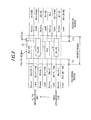
- FIG.4 shows a format composition of the pre-pit.
- FIG.4 shows a format composition of the pre-pit.
- two pre-pit regions 10, 11 neighboring in the radius direction are shown.
- a composition with doubled address information regions is employed.
- two sets of address mark AM (2B:2byte), sector address ID1 (3B), and error correction code IED1 (2B) of IDl are provided.
- VFO1 (variable frequency oscillator) (26B) before the sector address information region, and VF02 (12B) between the sector address information regions are provided.
- These regions, VFO1 and VFO2 are ones for the pull-in of clock; and use single-cycle signal, such as a 3T mark.
- post-amble region PA (1B) is provided as a modulation encoding.
- the shift amount SH is set so that the two sector address information regions in one of the adjacent pre-pit regions, e.g. the pre-pit region 11, are aligned to the regions, VFO1 and VFO2, of the other pre-pit region 10. Also, by the shift amount SH, the sector address information regions in the other pre-pit region are aligned to the regions, VFO1 and VFO2, of the one pre-pit region in the radius direction. Meanwhile, given blank regions, TA1 and TA2 which are formed as mirror regions, are provided at both sides of each pre-pit region in the circumference direction and between the pre-pit region and the recording region in the header region.
- the main object is to facilitate the detection of header region by forming TA1 and TA2 as mirror regions.
- the adjacent pre-pit region, as a crosstalk component, to the sector address information is VFO1 and VFO2 regions, where 3T marks, which are of short-mark signal, are carved and the mark width is physically smaller than sector address ID1 or ID2, unless making a special artifice by the cutting device. Therefore, even for defocusing of about ⁇ 1 ⁇ m, the crosstalk is less than -26 dB, which is a normal tolerance of optical disk devices.
- VFO1 and VFO2 regions are of single-cycle mark and the identification of crosstalk component is therefore clear, a method of removing the crosstalk described later is also applicable.
- the harmful effect of crosstalk can be reduced significantly without reducing the format efficiency.
- the VFOs in the neighboring pre-pit regions may interfere with each other, affecting the identification of data when the crosstalk occurs due to defocusing.
- at least the mutual recording mark edges 12 of the VFO1 regions in the neighboring pre-pit regions only have to be formed aligned in the radius direction.
- the recording mark edges may not be aligned in the radius direction.
- PLL phase lock loop circuit
- the problem caused by that the recording mark edges are not aligned in the radius direction does not occur since the phase lock can be obtained by a few clocks.
- a mirror region of several channel clocks is, for example, inserted between the IED1 and VFO2 in the adjacent pre-pit region 11 to be shifted.
- pre-pit region is of doubled composition, but it can be simplified by using a single composition. Also, a tripled or quadrupled composition is applicable similarly,
- FIG.5 is an enlarged plan view showing the recording surface of an optical disk in the second preferred embodiment according to the invention.
- the pre-pit regions are shifted alternately, for example, forward and backward in the circumference direction of the optical disk, in the radius direction.
- the alternate shifting is made forward, and for another predetermined number of tracks, the alternate shifting is made backward.
- the shift amount SH is the same value between the forward and backward sides, there may be different values therebetween.
- provided in this invention is an optical disk wherein specific information of neighboring pre-pit regions is not aligned in the radius direction so as to reduce the harmful effect of crosstalk.
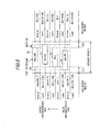
- the concept of the sector structure including a sector address as fundamentals of disk format is that the sector address number of each sector, which is common physical address information to land region 1 and groove region 2, increases sequentially, n, n+1, n+2, n+3, ..., where n is a positive integer, in the trace direction of the focused beam.
- the trace direction shown is clockwise from the inner circumference side to the outer circumference side, and address information shown is formed in reference to the groove region.
- N is the number of sectors in one physical track, and is a fixed number in case of ZCLV.
- N is an arbitrary offset number given by an address calculation circuit described after, which is used, for example, to facilitate the address management of land region and groove region.
- M is a fixed value on the entire surface of disk.
- the entire pre-pit region is shifted alternately in the radius direction of optical disk, So, the lengths of TA1 and TA2 vary between neighboring pre-pit regions in the radius direction of optical disk.
- the essential feature of optical disk according to the invention is that sector address regions are not aligned in the radius direction of optical disk.
- another embodiment can be, for example, composed so that the lengths of TA1 and TA 2 are fixed always and only the address region is shifted by an amount of SH.
- the length of VFO1 varies between neighboring pre-pits.
- a short mark sequence such as a VFO mark, can be inserted additionally.
- the pre-pit in the header region has a shape of concave/convex and a depth or height of ⁇ /10n to ⁇ /4n, where ⁇ is a wavelength of light beam and n is mainly a refractive index of substrate.
- the physical depth is determined by a thickness of resist unless making a special artifice. Therefore, if the depth or height of groove is made ⁇ /8n, the depth or height of pre-pit becomes equal.
- the modulation degree of pre-pit is reduced to less than the maximum bit depth, ⁇ /4n. Of course, it is well known that this depends on the detection system of track error signal.
- the amplitude of track error signal becomes maximum at ⁇ /4n. Therefore, when using the push-pull system, the pit depth is set to be, e.g. ⁇ /6n as a compromise point.
- the groove depth is also a compromise point considering a crosstalk in the recording region, but it is proved that a good playback performance is obtained even when setting about 70 nm nearly corresponding to a groove depth of ⁇ /6n.
- the pre-pit needs to have a width equal to or less than the track width of land/groove.
- the width of pre-pit is to be determined taking the SN ratio of address information identification into account while keeping less than the track width.
- the length of the shortest recording mark within the zone is shorter at the inner circumference side and longer at the outer circumference side.
- the length of the shortest recording mark on the surface of optical disk must be dispersed among the zones. If the length of the shortest recording mark is short, a playback error is likely to occur and there may occur a difference in playback performance of address information in the header region among the zones. It is undesirable in the light of reliability of disk. To avoid this as far as possible, the number of tracks provided for the zones at the inner and outer circumference sides are reduced so that the length of the shortest recording mark is almost uniform among the zones. According to this, there is an effect that dispersion in playback performance or recording performance among the zones becomes difficult to incur.
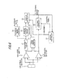
- FIG. 6 is a block diagram showing the main part of an optical disk device in the first preferred embodiment according to the invention.
- the optical disk device for conducting the recording/playback of an optical disk that includes a header region having a pre-pit region that is formed on the boundary part of neighboring land region and groove region and includes address information, the header region being disposed at every other boundary part, as shown in FIGS.3 and 5, comprising: a system controller 20 as means for outputting, in advance, identifier 1 to inform whether a recording track to be scanned by light beam is a land region or a groove region; a waveform shaper 21 and an address playback circuit 24 as a physical address information extraction means for extracting physical address information of a header region to be scanned by light beam; a track region detector 23 as means for outputting identifier 2 to inform the detection result as to whether a recording track to be scanned by light beam is a land region or a groove region; and an address calculator 25 as means for calculating address from identifier 1, identifier 2 and output of the physical address information extraction means, wherein header information is shared by neighboring groove and land.
- low-frequency component signal of header region superposed on track error signal gives a waveform that deviates, like 201 or 202, in the positive or negative side from the center 203 of track error signal. so, the track region detector 23 detects such positive or negative signal, binarizing this, thereby allowing the track detection which to detect a land region or a groove region to be obtained as binarized signal "1" or "0".
- the logical operation between this binarized signal used as identifier 2 and identifier 1 generated from the system controller 23 is conducted by the address calculator 25 composed of, e.g. an EXOR logical circuit. This allows the coincidence detection between a land or groove region designated and a land or groove region detected, Therefore, the misidentification of address caused by the malfunction of optical disk device can be prevented effectively.
- the read-out address information may be used unalteredly for groove region, or the linear conversion of address may be conducted based on a conversion table for land region.
- the re-reading of a target address can be conducted by a device operation including a retrying.
- the device can be prevented from incurring a runaway such as a misidentification of address.
- neighboring groove and land can share header information at good reliability.
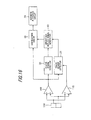
- FIG.8 is a block diagram showing the main part of an optical disk device in the second preferred embodiment according to the invention.
- the track region detector 23 for judging whether a recording track to be scanned by light beam is a land region or a groove region, for an optical disk that includes a header region having a pre-pit region that is formed on the boundary part of neighboring land region and groove region and includes address information, the header region being disposed every other boundary part, as shown in FIGS.3 and 5.
- amplifiers A, B and a track error detection circuit 111 are additionally provided as means for calculating address information by outputting push-pull signal by changing the output ratio of one signal and other signal from the division type optical detector 108, which detects push-pull signal, based on the output of track region detector 23.
- the conventional optical disk device described in Japanese patent No.2, 663, 817 conducts the playback of address information using wide-band push-pull signal.
- the conventional optical disk device since half of the light beam is projected on the pre-pit, there is a difference between amounts of signal received by the two optical detectors 108 divided to obtain push-pull signal, Therefore, in the conventional optical disk device, for push-pull signal as difference signal of the optical detectors, its in-phase compon'ent noise is not cancelled and its waveform is distorted. Especially when defocusing occurs, it is significant on the header side where crosstalk occurs.
- the circuit is composed so that push-pull signal, as difference signal, with the amplitude ratio between one signal output and other signal output changed from 1:1 is output.
- signals from the division type optical detector 108 pass through the amplifiers A and B whose amplification degree can be set by external signal, then outputting difference signal of both the signals from the track error detection circuit 111.
- the amplification degree of the amplifier A to the amplifier B is set, e.g., 1.2 times for land region, and the amplification degree of the amplifier B to the amplifier A is set, e.g., 1.2 times for groove region. Therefore, the in-phase component noise of push-pull signal becomes equal and the distortion of waveform can be prevented.
- the amplification degree is set to be zero at only one side, the detection of signal is conducted at only other side.
- the good push-pull signal output is binarized by the waveform shaper 21, and then address information is demodulated by the address playback circuit 24.
- the address information is calculated, with identifiers 1 and 2, by the address calculator in the same composition as shown in FIG.6.
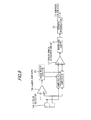
- FIG.9 is a block diagram showing the main part of an optical disk device in the third preferred embodiment according to the invention.
- FIG.10 is a signal waveform diagram showing the operation of the optical disk device.
- the playback add signal circuit 109 to output track add signal
- the track error detection circuit 110 to output track error signal 601 as wide-band push-pull signal, which is track difference signal
- the optical disk device for an optical disk that includes a header region having a pre-pit region that is formed on the boundary part of neighboring land region and groove region and includes address information, the header region being disposed every other boundary part, as shown in FIGS.3 and 5.
- a header region detector 30 to output header region signal 606 for indicating a header region position based on the track add signal, a differential circuit 31 to output first-order differential signal 602 based on track error signal 601, a zero cross circuit 33 to output differential cross signal 603 which is zero cross signal of the first-order differential signal 602, a window comparator 32 to binarize the first-order differential signal 602 by two predetermined positive and negative slice levels 620, 622 to an amplitude center level 621, and a logical operation circuit 34 to output track region detection signal 607 to determine whether a track scanned by light beam is a land region or a groove region, from the header region signal 606, the differential cross signal 603 and the window comparator's output signals 604, 605.
- the logical operation circuit 34 which is composed of, e.g. RS flip-flop circuit, receives differential cross signal 603 as data input, latching this using the rising edges of window comparator's output signals 604, 605 as set signal and reset signal, respectively, passing through a polarity inversion circuit, outputting the track region detection signal (land/groove signal) 607.
- the land region is output as "1"
- the groove region is output as "0".
- the forward header position corresponds to a header region viewed from the land region
- the backward header position corresponds to a header region viewed from the groove region.
- FIG. 11 is a block diagram showing the main part of an optical disk device in the fourth preferred embodiment according to the invention.
- This embodiment is applied to an optical disk device for an optical disk that includes a header region having a pre-pit region that is formed on the boundary part of neighboring land region and groove region and includes address information, the header region being disposed every other boundary part, as shown in FIGS.3 and 5.
- the header region detector 30 to detect the header region.
- a sample hold circuit 36 to sample a track error signal value at an arbitrary time before the output time of the header region detector 30 and to hold it for an arbitrary time
- an arbitrary waveform generating circuit 35 to generate arbitrary waveform signal
- an adder circuit 39 to add either or both of output signal of the sample hold circuit 36 and control signal from the system controller (its signal output is not shown) .
- a phase compensation filter 37 to output desired servo error signal based on servo error signal outputfrom the adder circuit 39, and a drive circuit 38 to drive the tracking actuator according to the servo error signal from the phase compensation filter 37.
- write gate signal (WGATE) which is gate signal for the start of recording, may be used to control the add timing of arbitrary function. Alternatively, it may always be added.
- the track error signal 201 or 202 incurs a large offset. This is because the header region is shifted by nearly half the pitch from the land or groove region where light beam scans and therefore a low-frequency component of the header region superposed on track error signal as push-pull signal causes a track offset. Becauseof this, track error signal after passing the header region makes a transient response and, in some cases, continues making the transient response. In such a condition that the tracking control is unstable, there may occur a problem that the following header address cannot be played back and the sector recording cannot be carried out continuously.
- the unstable-tracking-control condition can be avoided by using servo error signal from the sample hold circuit 36 that uses the output of header region signal from the header region detector 30, holding a track error signal value of at least several bytes of sector format before the output time, from the finish of header region signal until just before the recording starts.
- the tracking control may be unstable. So, in this embodiment, further by measuring signal of track offset waveform occurring at the header region to be detected by the header region detector 30 by a previous learning etc., then, for example, subtracting this from the servo error signal in the adder circuit 39, the track follow-up performance can be stabilized. Also, other than the simple reverse function of track offset waveform, an arbitrary waveform generated by the arbitrary waveform generating circuit 35 can be added or subtracted to produce servo error signal while securing the stability of the servo control system including actuator system.
- the arbitrary waveform may be, for example, a rectangular pulse with arbitrary height and width.
- the arbitrary values may be determined taking a step response waveform of the servo system including actuator system into account. Also, they may be, of course, simply a DC value. This corresponds to the simple adding/subtracting of track offset, and, in this case, by using write gate signal (WGATE) which is gate signal for the start of recording, the timing of adding/subtracting may be controlled.
- WGATE write gate signal
- the selection of signal from the arbitrary waveform generating circuit 35 can be conducted based on land/groove signal from the system controller or the track region detector, described earlier, that conducts the detection of land/groove signal to detect whether the recording track scanned by light beam is a land region or a groove region.
- the arbitrary waveform generating circuit 35 is, for example, composed so that an A/D converter takes in track error signal, e.g., only near the header region for a predetermined time, accumulating it into a RAM memory, and a D/A converter converts it when outputting the signal.
- the reverse function of track offset waveform can be obtained.
- the signal when generating a true arbitrary waveform, by providing an operation means to develop the function on a RAM memory, the signal can be output by using a D/A converter.
- many kinds of arbitrary waveforms can be, of course, prepared in advance by the address management on RAM.
- FIG. 12 is a block diagram showing the main part of an optical disk device in the fifth preferred embodiment according to the invention.
- This embodiment is applied to an the optical disk device for an optical disk that includes a header region having a pre-pit region that is formed on the boundary part of neighboring land region and groove region and includes address information, the header region being disposed every other boundary part, as shown in FIGS.3 and 5.
- a division type optical detector 150 for the detection of focus error signal is provided.
- the header region detector 30 to detect the header region
- a sample hold circuit 41 to sample a focus error signal value at an arbitrary time before the output time of the header region detector 30 and to hold it for an arbitrary time
- an arbitrary waveform generating circuit 40 to generate arbitrary waveform signal
- an adder circuit 44 to add either or both of output signal of the sample hold circuit 41 and control signal from the system controller (its signal output is not shown)
- a phase compensation filter 42 to output desired servo error signal
- WGATE write gate signal
- the unstable-focus-control condition can be avoided by using servo error signal from the sample hold circuit 41 that uses the output of header region signal from the header region detector 30, holding a focus error signal value of at least several bytes of sector format before the output time, from the finish of header region signal until just before the recording starts.
- the focus control may be unstable. So, in this embodiment. further by measuring signal of focus offset waveform occurring at the header region to be detected by the header region detector 30 by a previous learning etc., then subtracting this from the servo error signal in the adder circuit 44, the focus follow-up performance can be stabilized. Also, other than the simple reverse function of focus offset waveform, an arbitrary waveform generated by the arbitrary waveform generating circuit 40 can be added or subtracted to produce servo error signal while securing the stability of the servo control system including actuator system.
- the arbitrary waveform may be, for example, a rectangular pulse with arbitrary height and width.
- the arbitrary values may be determined taking a step response waveform of the servo system including actuator system into account. Also, they may be, of course, simply a DC value. This corresponds to the simple adding/subtracting of focus offset, and, in this case, by using write gate signal (WGATE) which is gate signal for the start of recording, the timing of adding/subtracting may be controlled.
- WGATE write gate signal
- the selection of signal from the arbitrary waveform generating circuit 40 can be conducted based on land/groove signal from the system controller or the track region detector, described earlier, that conducts the detection of land/groove signal to detect whether the recording track scanned by light beam is a land region or a groove region.
- the arbitrary waveform generating circuit 40 is, for example, composed so that an A/D converter takes in focus error signal, e.g., only near the header region for a predetermined, time, accumulating it into a RAM memory, and a D/A converter converts it when outputting the signal.
- an A/D converter takes in focus error signal, e.g., only near the header region for a predetermined, time, accumulating it into a RAM memory, and a D/A converter converts it when outputting the signal.
- the reverse function of focus offset waveform can be obtained.
- the signal when generating a true arbitrary waveform, by providing an operation means to develop the function on a RAM memory, the signal can be output by using a D/A converter.
- FIG.14 is a block diagram showing the main part of an optical disk device in the sixth preferred embodiment according to the invention.
- the optical disk device in this embodiment which is applied to an optical disk as shown in FIGS.3 and 5, comprises a playback add signal circuit 109 to output track add signal of the division type optical detector 108, an envelope detection circuit 50 to output the envelop signal of track add signal, a binarization circuit 51 to binarize the envelope signal, a burst detection circuit 53 to output burst detection signal from burst signal with a specific mark including the track add signal, and a logical operation circuit 52 to output header region signal, which is the binarized signal almost enclosing the header region, from output signal of the binarization circuit 51 and the burst detection signal.
- the burst signal with a specific mark is signal VFO1 of pre-pit region shown in FIG.4, and is single-cycle signal, such as a 3T mark.
- FIG.15 is a waveform diagram showing the operation of the optical disk device in this embodiment.
- 610 is track add signal
- 611 is signal near the header region
- 612 is a recording data region
- 613 is an erase level (unrecorded level) in a phase change disk.
- the output level of envelop signal to the track add signal 610 is 615 and the threshold level of the binarization circuit 51 is set to be at the middle level between 615 and 613
- rough header detection signal 616 is output.
- the rough header detection signal 616 must be output even for a defect or dust in the optical disk.
- burst detection signal 617 in VFO1 region is detected by the burst detection circuit 53, the rough header detection signal 616 is subject to a logical operation by the logical operation circuit 52 composed of, e.g., a flip-flop circuit, thereby header region detection signal with good reliability can be output.
- header region signal 619 which is binarized signal almost enclosing the header region, is output.
- the burst signal is detected from the track add signal, it may be detected from push-pull signal, which is track difference signal.
- FIG.16 is a block diagram showing the main part of an optical disk device in the seventh preferred embodiment according to the invention.
- crosstalk replica signal is easy to generate.
- the optical disk device in this embodiment comprises a crosstalk replica signal generating circuit 60, a subtraction circuit 61 to subtract the crosstalk replica signal from the pre-pit signal component of track add signal, e.g. by using timing control signal from the system controller (not shown), and an address playback circuit 24 to play back address information from output of the subtraction circuit 61.
- the crosstalk replica signal may be subtracted uniformly from the pre-pit signal component only when the header region detection signal is output.
- the crosstalk replica signal generating circuit 60 When the focused beam scans a land region, the crosstalk replica signal generating circuit 60 generates a replica of pre-pit playback signal with 3T mark so as to remove a crosstalk component from VFO2 in the neighboring pre-pit region, generating crosstalk replica signal by setting the gain ratio to the pre-pit signal component to be, e.g. 15%, caking the crosstalk amount into account.
- the crosstalk replica signal generating circuit 60 is, like the composition of the arbitrary waveform generating circuit described earlier, composed of an operation means to develop the function on a RAM memory, where the signal is output by using a D/A converter.
- the sector address information etc. is played back from the track add signal
- the sector address information may be played back from push-pull signal, which is track difference signal.
- the neighboring pre-pit regions in the header region with may have different lengths so that parts of address information in the neighboring pre-pit regions are not aligned in the radius direction.
- phase change type optical disks are used in the above embodiments, a magneto-optic disk and a playback-only reflection type optical disk are also applicable. Also, the optical disk devices in the above embodiments are applicable to the playback/recording of these optical disks.
- the (1,7) modulation system and the mark edge recording are used in the embodiments, coding of other modulation/demodulation system and a mark position recording may be used.
- ZCLV zoned constant angular velocity
- CAV complex CAV
- the sector address information etc. is played back from the track add signal
- the sector address information may be played back from push-pull signal, which is track difference signal.
- compositions to solve the problem of the optical disk described in Japanese patent No.2,663,817 are disclosed, another header arrangement can be used so that parts of address information in the pre-pit regions neighboring in the radius direction are not aligned in the radius direction.
- a composition which is described in Japanese patent No.2,788,022, that pre-pits are arranged on the right and left sides of the boundary of land and groove.
- the pre-pit regions including specific information are formed at the boundary part of neighboring land region and groove region and are disposed every other boundary part, and specific information in the neighboring pre-pit regions is not aligned in the radius direction of the optical disk. Therefore, the crosstalk effect from the neighboring pre-pit region can be suppressed. Even when defocusing of the light beam occurs due to an error in the manufacturing of the head or a deterioration in head performance with age, misidentification of address information in the pre-pit region can be reduced significantly. Accordingly, the reduction of throughput in the optical disk device can be prevented, thereby the reliability of device or disk can be enhanced.
- the influence of the pre-pit to servo error signal is to cause the focus offset and the disorder of track error signal, thereby incurring a unstable recording/playback.
- the influence of the pre-pit to servo error signal is to cause the focus offset and the disorder of track error signal, thereby incurring a unstable recording/playback.
- the focus offset due to the chromatic aberration of objective lens by a phenomenon called a jump of wavelength in semiconductor laser, thereby causing a failure in recording.
- the optical disk device of this invention can offer stable header detection and address identification. Also, the sharing of address by land and groove can be performed with good reliability. Further, the stability of playback/recording at data region can be enhanced.
Abstract
Description
- This invention relates to a disk format on optical disk, and to an optical disk device that can conduct the recording and playback of such an optical disk.
- In recent years, for a rewritable optical disk with a large capacity, a land/groove recording system that a region between grooves is also used as an information track, as well as a groove provided as a guide trench on optical disk has been suggested. The land and groove may be called convex part and concave part, respectively, or called inter-groove part and groove part, respectively. First, an optical disk used in the conventional land/groove recording system is explained.
- FIG.1 is a partial enlarged plan view showing a conventional optical disk that is described in Japanese patent No.2,663,817. In FIG.1, G indicates a groove region, L indicates a land region, Tp indicates a track pitch, P indicates a pre-pit, and BS indicates a focused beam spot. Also, "identification signal region" in Japanese patent No.2, 663,817 is called "header region" herein. In this disk format, a header region including address information is shared between adjacent groove G and land L, and at least a part of information signal included in header region is shifted by Tp/4 to the center line of groove G and to the center line of land L, and in at least part of optical disk, the header region and recording data region each are formed in a radial pattern.
- FIG.2 is a block diagram showing the composition of an optical disk device used for the optical disk above. In FIG.2, 100 is the optical disk, 103 is a half mirror serving as a beam splitter, 104 is an objective lens to converge collimated light passed through the
half mirror 103 onto theoptical disk semiconductor laser optical disk 100 passing though theobjective lens 104 and thehalf mirror 103. The optical detector is composed of two light-receiving parts that are divided in parallel to the track direction (tangential direction of circumference) of the optical disk to obtain the tracking error signal. 102 is an actuator supporting theobjective lens 104. Meanwhile, part 101 enclosed by a dotted line in FIG.2 is attached to a head base (not shown), and compose an optical head. - On the other hand, 110 is a differential amplifier to which a detection signal to be output from the
optical detector 108 is input. 117 is a polarity inverter to which a tracking error signal from thedifferential amplifier 110 and a control signal L4 from a system controller 11B described later are input, and which controls the polarity of tracking error signal output to atracking controller 116 according to the control signal L4. Hereupon, regarding the polarity of tracking control, when tracking error signal is input, with its polarity unaltered, from thedifferential amplifier 110 to thetracking controller 116, the tracking is pulled into the recording track of groove G. 116 is the tracking controller to which an output signal from the polarity inverter, 117 and a control signal L1 from thesystem controller 118 are input, and which outputs tracking control signal to adriver 122 and atraverse controller optical detector 108 is input and which outputs an add signal. 112 is a waveform shaper to which an RF component from the adder amplifier is input, and which outputs a digital signal to aplayback signal processor 113 and aaddress playback circuit 114. 113 is the playback signal processor which outputs playback data to the output terminal. 114 is the address playback circuit to which digital signal from thewaveform shaper 112 is input, and which outputs an address signal. 115 is an address calculator to which address signal from theaddress playback circuit 114 and control signal L4 from thesystem controller 118 are input, and which outputs address signal to thesystem controller 118. - Also, 121 is the traverse controller which outputs drive current according to control signal from the
system controller 118. 107 is a traverse motor which moves the optical head 101 in the radius direction of theoptical disk 100 according to drive current from thetraverse controller 121. 119 is a record signal processor to which record data is input and which outputs record signal to a laser (LD)driver 120. 120 is the LD driver to which control signal from thesystem controller 118 and record signal from therecord signal processor 119 are input, and which supplies drive current to thesemiconductor laser 106. 122 is the driver to which tracking control signal from thetracking controller 116 is input and which supplies drive current to theactuator 102. Meanwhile, thesystem controller 118 which outputs control signal L1, L4 to thetracking controller 116, thetraverse controller 121, theaddress calculator 115, thepolarity inverter 117, therecord signal processor 119 and theLD driver 120, and to which address signal from theaddress calculator 115 is input. - The operation of the conventional optical disk device thus composed is explained below.
- Light output from the
semiconductor laser 106 is collimated by thecollimator lens 105, passed through thebeam splitter 103, converged onto theoptical disk 100 by theobjective lens 104. Laser light reflected on theoptical disk 100 holds the information of record track, passing through theobjective lens 104, being led through thebeam splitter 103 to theoptical detector 108. Theoptical detector 108 converts a variation in light quantity distribution of light beam supplied into electrical signal, outputting it to thedifferential amplifier 110, theadder amplifier 109. Thedifferential amplifier 110 current-voltage-converts (I-V conversion) currents input, taking the difference of both voltages, outputting it as push-pull signal. The polarity inverter 117 judges whether the track accessed is a land or a groove according to control signal L4 from thesystem controller 118, inverting the polarity, for example, only when the track is a land. Thetracking controller 116 outputs tracking control signal to thedriver 122 according to the level of tracking error signal input, thedriver 122 supplies current to the actuator according to this signal to control the position of theobjective lens 104 in the radius direction across the recording track. Thereby, the optical spot can scan precisely on the track. - On the other hand, the
adder amplifier 109 current-voltage-converts (I-V conversion) two currents output from the light-receivingpart 108, adding both, outputting it as add signal to thewaveform shaper 112. The waveform shaper 112 shapes data signal and address signal with an analogue waveform into a pulse waveform by data-slicing by a certain threshold value, outputting it to theplayback signal processor 113 and theaddress playback circuit 114. Theplayback signal processor 113 demodulates digital data signal input, conducting the processing of error correction etc. to output it as playback data. Theaddress playback circuit 114 demodulates digital address signal input, outputting it as position information on the disk to theaddress calculator 115. Theaddress calculator 115 calculates the address of a sector accessed from address signal read out from theoptical disk 100 and land/groove signal from thesystem controller 118. The calculation method is to judge referring to an address map etc. and then output the judgement signal. - The
system controller 118 judges whether the light beam currently locates at a desired address based on this address signal. Thetraverse controller 121 outputs drive current to thetraverse motor 107 according to control signal from thesystem controller 118 when shifting the optical head 101, thereby the optical head 101 is shifted to a target track. Hereupon, thetracking controller 116 suspends the tracking servo according to control signal L1 from thesystem controller 118. Also, in the normal playback mode, thetraverse motor 107 is driven according to tracking error signal input from thetracking controller 116, and the optical head 101 is moved gradually in the radius direction as the playback operation proceeds. Therecord signal processor 119 adds an error correction code etc. to record data input, outputting it as encoded record data to theLD driver 120. When thesystem controller 118 sets the recording mode by control signal, theLD driver 120 modulates drive current applied to thesemiconductor laser 106 according to record signal. Thereby, the intensity of light spots projected onto theoptical disk 100 varies according to the record signal, record pits are formed. On the other hand, in the playback operation, theLD driver 120 is set to the playback mode by control signal, the drive current is controlled so that thesemiconductor laser 106 emits light at a constant intensity. Thereby, the detection of record pit and pre-pit on record track is enabled. - Meanwhile, Japanese patent No.2, 663,817 discloses not only a technique that the detection of record pit and pre-pit is conducted using track add signal but also a way to detect a pre-pit using push-pull signal which is track difference signal. Namely, since the header region is positioned offsetting by Tp/4 from the record track in the radius direction, the detection using push-pull signal is enabled.
- However, the optical disk and optical disk device using the land region and groove region as an information track have a significant weakness for the defocusing of focused beam. Namely, due to an error in the manufacturing of head or a deterioration in head performance with age, so-called defocusing that focused beam is converged deviating from a right focus position occurs. Hereupon, in the optical disk described above, information of adjacent header regions affects as a crosstalk. Especially, when one address information is a signal of short mark and other to crosstalk is a signal of long mark, a significant distortion of waveform is observed and an error in the reading of address information occurs. In this case, since the header region needs to be played back while waiting for the rotation, the throughput may be reduced. Also, when it is played back again, the reading error is highly like to recur. Therefore, since it may be registered as a defect sector, the reliability of device and disk must be thus reduced.
- Also, in the optical disk device above, since the header region including address information is shared between adjacent groove and land, when an address to start the recording/playback is designated, the system controller judges whether the designated address is the land region or groove region by referring to an address map etc. Then, judgement signal (polarity signal) is output to the tracking servo system. After the tracking, detection signal of the physical address is address-converted by the judgement signal, thereby it is judged whether the tracking is carried out to the designated address. However, for example, when a large track offset occurs due to the failure of tracking, the tracking to the land or groove may not be performed as designated by polarity signal. Therefore, the judgement of address becomes unsuccessful and the operation of the device goes out of control.
- Also, in the header region, the influence of the pre-pit to servo error signal is to cause the focus offset and the disorder of track error signal, thereby incurring a unstable recording/playback. At the same time, when starting the recording after'passing the header region, depending on the composition of optical head, there occurs a focus offset due to the chromatic aberration of an objective lens, by a phenomenon called a jump of wavelength in semiconductor laser. This focus offset interferes with the focus offset occurring near the header region, thereby the focus control is made to be further unstable, causing a failure in recording.
- Accordingly, it is an object of the invention to provide an optical disk with an enhanced reliability.
- It is a further object of the invention to provide an optical disk device with excellent stability of recording/playback.
- According to the invention, an optical disk, comprises:
- a land region and a groove region that are formed on a substrate, the land region and groove region being used as a recording track that is the medium of the recording/playback of information signal; and
- a pre-pit region that is formed at the boundary part of neighboring land region and groove region and is disposed every other boundary part, the pre-pit region including specific information;
- wherein the specific information in neighboring pre-pit regions is not aligned in the radial direction of the optical disk.
-
- According to another aspect of the invention, an optical disk device for conducting the recording/playback of an optical disk comprising a land region and a groove region that are formed on a substrate, the land region and groove region being used as a recording track that is the medium of the recording/playback of information signal, and a pre-pit region that is formed at the boundary part of neighboring land region and groove region and is disposed every other boundary part, the pre-pit region including address information, comprises:
- means for outputting, in advance, as
identifier 1 whether a recording track scanned by light beam is a land region or a groove region; - a track region detection means for detecting whether the
recording track scanned by light beam is a land region or a groove
region and outputting the detection result as
identifier 2; - an address information extraction means for extracting address information from the pre-pit region scanned by light beam; and
- means for conducting the address calculation by receiving
the inputs of the
identifier 1,identifier 2 and address information. -
- According to another aspect of the invention, an optical disk device for conducting the recording/playback of an optical disk comprising a land region and a groove region that are formed on a substrate, the land region and groove region being used as a recording track that is the medium of the recording/playback of information signal, and a pre-pit region that is formed at the boundary part of neighboring land region and groove region and is disposed every other boundary part, the pre-pit region including address information, comprises:
- a track region detection means for detecting whether a recording track scanned by light beam is a land region or a groove region;
- means for detecting a push-pull signal as a track difference signal based on the output of the track region detection means;
- a calculation means for calculating the track difference signal by setting a subtraction ratio between one signal output and another signal output of the two signal outputs used to calculate the track difference signal; and
- means for detecting address information from the output of the calculation means.
-
- According to another aspect of the invention, an optical disk device for conducting the recording/playback of an optical disk comprising a land region and a groove region that are formed on a substrate, the land region and groove region being used as a recording track that is the medium of the recording/playback of information signal, and a pre-pit region that is formed at the boundary part of neighboring land region and groove region and is disposed every other boundary part, the pre-pit region including address information, comprises:
- a header region detection means for outputting header region signal to indicate the position of a header region including the pre-pit region from a track add signal;
- means for outputting first-order differential signal from a push-pull signal as a track difference signal;
- means for outputting differential cross signal from the zero cross signal of the first-order differential signal;
- a window comparator means for binarizing the amplitude of the first-order differential signal at a predetermined slice level; and
- a logical operation means for outputting track region detection signal to determine whether a track scanned by light beam is a land region or a groove region, from the header region signal, differential cross signal and output signal of the window comparator means.
-
- According to another aspect of the invention, an optical disk device for conducting the recording/playback of an optical disk comprising a land region and a groove region that are formed on a substrate, the land region and groove region being used as a recording track that is the medium of the recording/playback of information signal, and a pre-pit region that is formed at the boundary part of neighboring land region and groove region and is disposed every other boundary part, the pre-pit region including address information, comprises:
- means for outputting signal to detect whether a recording track scanned by light beam is a land region or a groove region;
- a header region detection means for detecting a header region including the pre-pit region; and
- a servo error detection means for sampling a track error signal value at an arbitrary time before the output time of the header region detection means, and holding the track error signal value an arbitrary time or conducting an operation of the track error signal value and arbitrary waveform signal then outputting the operation result as servo error signal.
-
- According to another aspect of the invention, an optical disk device for conducting the recording/playback of an optical disk comprising a land region and a groove region that are formed on a substrate, the land region and groove region being used as a recording track that is the medium of the recording/playback of information signal, and a pre-pit region that is formed at the boundary part of neighboring land region and groove region and is disposed every other boundary part, the pre-pit region including address information, comprises:
- means for outputting signal to detect whether a recording track scanned by light beam is a land region or a groove region;
- a header region detection means for detecting a header region including the pre-pit region; and
- a servo error detection means for sampling a focus error signal value at an arbitrary time before the output time of the header region detection means, and holding the track error signal value an arbitrary time or conducting an operation of the focus error signal value and arbitrary waveform signal then outputting the operation result as servo error signal.
-
- According to another aspect of the invention, an optical disk device for conducting the recording/playback of an optical disk comprising a land region and a groove region that are formed on a substrate, the land region and groove region being used as a recording track that is the medium of the recording/playback of information signal, and a pre-pit region that is formed at the boundary part of neighboring land region and groove region and is disposed every other boundary part, the pre-pit region including address information, comprises:
- means for outputting envelope signal or peak hold signal from track add signal to be input;
- means for binarizing the envelope signal or peak hold signal to be input;
- a burst detection means for detecting burst signal with a specific mark included in the pre-pit region then outputting burst detection signal; and
- a logical operation means for outputting binarized signal nearly enclosing the pre-pit region based on the output signal of the binarizing means and the burst detection signal.
-
- According to another aspect of the invention, an optical disk device for conducting the recording/playback of an optical disk comprising a land region and a groove region that are formed on a substrate, the land region and groove region being used as a recording track that is the medium of the recording/playback of information signal, and a pre-pit region that is formed at the boundary part of neighboring land region and groove region and is disposed every other boundary part, the pre-pit region including address information, comprises:
- means for generating replica signal under a condition that a crosstalk component from the neighboring pre-pit region at a position where address information is played back is clearly detected; and
- a crosstalk removing means for removing the replica signal as crosstalk component from a signal component played back.
-
- The invention will be explained in more detail in conjunction with the appended drawings, wherein:
- FIG.1 is an enlarged partial plan view showing the format of the conventional optical disk.
- FIG.2 is a block diagram showing the composition of the conventional optical disk device,
- FIG.3 is an enlarged partial plan view showing the format of an optical disk in a first preferred embodiment according to the invention,
- FIG.4 is an illustration showing an example of the sector format of optical disk according to the invention,
- FIG.5 is an enlarged partial plan view showing the format of an optical disk in a second preferred embodiment according to the invention,
- FIG.6 is a block diagram showing main part of an optical disk device in a first preferred embodiment according to the invention,
- FIG.7 is an illustration showing the idea of track error offset signal generated at the header region,
- FIG.8 is a block diagram showing main part of an optical disk device in a second preferred embodiment according to the invention,
- FIG.9 is a block diagram showing main part of an optical disk device in a third preferred embodiment according to the invention,
- FIG.10 is a waveform diagram showing the operation of the optical disk device in FIG.9,
- FIG.11 is block diagram showing main part of an optical disk device in a fourth preferred embodiment according to the invention,
- FIG. 12 is block diagram showing main part of an optical disk device in a fifth preferred embodiment according to the invention,
- FIG.13 is an illustration showing the idea of focus error offset signal generated at the header region,
- FIG.14 is block diagram showing main part of an optical disk device in a sixth preferred embodiment according to the invention,
- FIG.15 is a waveform diagram showing the operation of the optical disk device in FIG.14, and
- FIG.16 is block diagram showing main part of an optical disk device in a seventh preferred embodiment according to the invention.
-
- The preferred embodiments of the invnetion will be explained below, referring to the drawings.
- Here, (1,7)RLL is used as a modulation system and mark edge recording is used as a recording system. As the control system for the rotation of optical disk, ZCLV (zoned constant linear velocity) is used. In this embodiment, taken as an example of optical disk allowing the recording/playback is a phase change (PC) type optical disk that the recording is conducted according to the change of real reflectivity. Also, for example, a focused beam diameter (1/e2) is 0.95 µm, and each track width of land/groove is 0.58 µm.
- First, an optical disk according to the invention is explained below.
- FIG.3 is an enlarged plan view showing the recording surface of an optical disk in the first preferred embodiment according to the invention. As shown, a header region is placed between recording regions in the scanning direction of light beam to scan each of land region (Land) as convex part of optical disk and groove region (Groove) as concave part adjacent to the land region, i.e. in the circumferencial direction of optical disk. In this header region and on the boundary part between the land region (Land) and the groove region (Groove), pre-pit regions that show physical address information common to the land region (Land) and the groove region (Groove) are disposed every other boundary part. Namely, the pre-pit regions are disposed deviating by Tp/4 every other boundary part to a crack pitch Tp of the land region or groove region. This arrangement is similar to that in the conventional optical disk. Here, in this invention, in order that pre-pit regions in header regions neighboring in the radius direction of optical disk are not aligned in the radius direction, to a pre-pit region on one boundary part, a pre-pit region neighboring in the radius direction is alternately shifted by several bytes, for example, backward or forward in the circumference directionof optical disk. Also, it is, of course, applicable to shift the pre-pit region alternately forward and backward in each sector in the circumference direction so that adjacent pre-pit regions are not aligned in the radius direction.
- Here, an amount SH of the shifting described above in the pre-pit region is explained below.
- FIG.4 shows a format composition of the pre-pit. In FIG.4, of the several pre-pits shown in FIG.3, two
pre-pit regions - In this case, the shift amount SH is set so that the two sector address information regions in one of the adjacent pre-pit regions, e.g. the
pre-pit region 11, are aligned to the regions, VFO1 and VFO2, of the otherpre-pit region 10. Also, by the shift amount SH, the sector address information regions in the other pre-pit region are aligned to the regions, VFO1 and VFO2, of the one pre-pit region in the radius direction. Meanwhile, given blank regions, TA1 and TA2 which are formed as mirror regions, are provided at both sides of each pre-pit region in the circumference direction and between the pre-pit region and the recording region in the header region. These are also needed to give a transfer time to a cutting device to make a pre-format when moving light beam by Tp/4 in the radius direction in case of one-beam cutting device. However, the main object is to facilitate the detection of header region by forming TA1 and TA2 as mirror regions. - In conducting, the recording/playback of information by scanning laser light onto the optical disk, defocusing or radial tilting, described earlier in prior art, to one pre-pit region as a scan target mayoccur. However, the adjacent pre-pit region, as a crosstalk component, to the sector address information is VFO1 and VFO2 regions, where 3T marks, which are of short-mark signal, are carved and the mark width is physically smaller than sector address ID1 or ID2, unless making a special artifice by the cutting device. Therefore, even for defocusing of about ±1 µm, the crosstalk is less than -26 dB, which is a normal tolerance of optical disk devices. Also, since the VFO1 and VFO2 regions are of single-cycle mark and the identification of crosstalk component is therefore clear, a method of removing the crosstalk described later is also applicable. Thus, by shifting by the shift amount SH the neighboring pre-pit region in the header region, the harmful effect of crosstalk can be reduced significantly without reducing the format efficiency.
- Even when the composition of the pre-pit region described above is employed, for a narrower track pitch Tp to provide a higher-density medium, the VFOs in the neighboring pre-pit regions may interfere with each other, affecting the identification of data when the crosstalk occurs due to defocusing. In this case, as shown in FIG.4, at least the mutual recording mark edges 12 of the VFO1 regions in the neighboring pre-pit regions only have to be formed aligned in the radius direction. Thus, by aligning the recording mark edges in the radius direction, the interference between the VFOs in the neighboring pre-pit regions can be suppressed.
- Meanwhile, as to the VFO2 region, depending on the length of AM, ID1 and IED1, the recording mark edges may not be aligned in the radius direction. However, in the VFO2 region, when conducting only the pull-in of phase using PLL (phase lock loop) circuit (not shown) for the extraction of playback clock, the problem caused by that the recording mark edges are not aligned in the radius direction does not occur since the phase lock can be obtained by a few clocks. Also, though not shown, in order to align certainly the recording mark edge of VF02 region in the radius direction, it is applicable that a mirror region of several channel clocks is, for example, inserted between the IED1 and VFO2 in the adjacent
pre-pit region 11 to be shifted. In this case, although the length of pre-pit region differs between the adjacent pre-pit regions, the VFO regions do not interfere with each other even for a further high-density medium, and the extraction of clock can be made stable. In this embodiment the pre-pit region is of doubled composition, but it can be simplified by using a single composition. Also, a tripled or quadrupled composition is applicable similarly, - FIG.5 is an enlarged plan view showing the recording surface of an optical disk in the second preferred embodiment according to the invention. The difference from the optical disk in FIG.3 is that in order not to align neighboring pre-pit regions in the radius direction, the pre-pit regions are shifted alternately, for example, forward and backward in the circumference direction of the optical disk, in the radius direction. Of course, there exist some variations other than this. For example, for a predetermined number of tracks, the alternate shifting is made forward, and for another predetermined number of tracks, the alternate shifting is made backward. Although in FIG.5 the shift amount SH is the same value between the forward and backward sides, there may be different values therebetween. In any case, provided in this invention is an optical disk wherein specific information of neighboring pre-pit regions is not aligned in the radius direction so as to reduce the harmful effect of crosstalk.
- Also, the concept of the sector structure including a sector address as fundamentals of disk format is that the sector address number of each sector, which is common physical address information to land
region 1 andgroove region 2, increases sequentially, n, n+1, n+2, n+3, ..., where n is a positive integer, in the trace direction of the focused beam. Herein, the trace direction shown is clockwise from the inner circumference side to the outer circumference side, and address information shown is formed in reference to the groove region. Also, N is the number of sectors in one physical track, and is a fixed number in case of ZCLV. N is an arbitrary offset number given by an address calculation circuit described after, which is used, for example, to facilitate the address management of land region and groove region. For example, M is a fixed value on the entire surface of disk. - Meanwhile, in the above embodiments, the entire pre-pit region is shifted alternately in the radius direction of optical disk, So, the lengths of TA1 and TA2 vary between neighboring pre-pit regions in the radius direction of optical disk. However, as defined in the appended claims, the essential feature of optical disk according to the invention is that sector address regions are not aligned in the radius direction of optical disk. Namely, another embodiment can be, for example, composed so that the lengths of TA1 and
TA 2 are fixed always and only the address region is shifted by an amount of SH. In this case, the length of VFO1 varies between neighboring pre-pits. Also, when the address region after VF02 is shifted forward, a short mark sequence, such as a VFO mark, can be inserted additionally. - Also, though not shown, the pre-pit in the header region has a shape of concave/convex and a depth or height of λ/10n to λ/4n, where λ is a wavelength of light beam and n is mainly a refractive index of substrate. In fact, when making an initial disk, the physical depth is determined by a thickness of resist unless making a special artifice. Therefore, if the depth or height of groove is made λ/8n, the depth or height of pre-pit becomes equal. Hereupon, though the amplitude of track error signal by push-pull system becomes maximum, the modulation degree of pre-pit is reduced to less than the maximum bit depth, λ/4n. Of course, it is well known that this depends on the detection system of track error signal. In an error detection system such as heterodyne, the amplitude of track error signal becomes maximum at λ/4n. Therefore, when using the push-pull system, the pit depth is set to be, e.g. λ/6n as a compromise point. Of course, when using a phase change type optical disk medium, the groove depth is also a compromise point considering a crosstalk in the recording region, but it is proved that a good playback performance is obtained even when setting about 70 nm nearly corresponding to a groove depth of λ/6n.
- Further, as to the shape of pre-pit in the header region, the pre-pit needs to have a width equal to or less than the track width of land/groove. For example, for a focused beam of 0.95 µm and a track width of about 1.58 µm, even under the condition that an external factor such as defocusing and radial tilting does not exist, the amount of crosstalk from the adjacent header region has a degree that slightly exceeds a tolerance of device, -26 dB. Therefore, considering the viewpoint of crosstalk, the width of pre-pit is to be determined taking the SN ratio of address information identification into account while keeping less than the track width.
- Also, in dividing the surface of optical disk into multiple zones, when the zone with is made uniform, the length of the shortest recording mark within the zone is shorter at the inner circumference side and longer at the outer circumference side. Thus, the length of the shortest recording mark on the surface of optical disk must be dispersed among the zones. If the length of the shortest recording mark is short, a playback error is likely to occur and there may occur a difference in playback performance of address information in the header region among the zones. It is undesirable in the light of reliability of disk. To avoid this as far as possible, the number of tracks provided for the zones at the inner and outer circumference sides are reduced so that the length of the shortest recording mark is almost uniform among the zones. According to this, there is an effect that dispersion in playback performance or recording performance among the zones becomes difficult to incur.
- Next, an optical disk device according to the invention is explained. Meanwhile, in the embodiments below, the composition of the conventional optical disk device shown in FIG.2 is incorporated into the background of this invention, and components different from the conventional disk device are shown and mainly explained.
- FIG. 6 is a block diagram showing the main part of an optical disk device in the first preferred embodiment according to the invention.
- The optical disk device for conducting the recording/playback of an optical disk that includes a header region having a pre-pit region that is formed on the boundary part of neighboring land region and groove region and includes address information, the header region being disposed at every other boundary part, as shown in FIGS.3 and 5, comprising: a
system controller 20 as means for outputting, in advance,identifier 1 to inform whether a recording track to be scanned by light beam is a land region or a groove region; awaveform shaper 21 and anaddress playback circuit 24 as a physical address information extraction means for extracting physical address information of a header region to be scanned by light beam; atrack region detector 23 as means for outputtingidentifier 2 to inform the detection result as to whether a recording track to be scanned by light beam is a land region or a groove region; and anaddress calculator 25 as means for calculating address fromidentifier 1,identifier 2 and output of the physical address information extraction means, wherein header information is shared by neighboring groove and land. - Namely, since the conventional optical disk device described in Japanese patent No.2,663,817 conducts the address calculation using only identifier 1 (=L4 in '817) in this embodiment, a misidentification of address may occur due to the malfunction of the optical disk device. So, this invention solves this problem by adding
identifier 2 as output of thetrack region detector 23. - When scanning a land region (Land) or a groove region (Groove) as shown in FIG.7, low-frequency component signal of header region superposed on track error signal gives a waveform that deviates, like 201 or 202, in the positive or negative side from the
center 203 of track error signal. so, thetrack region detector 23 detects such positive or negative signal, binarizing this, thereby allowing the track detection which to detect a land region or a groove region to be obtained as binarized signal "1" or "0". The logical operation between this binarized signal used asidentifier 2 andidentifier 1 generated from thesystem controller 23 is conducted by theaddress calculator 25 composed of, e.g. an EXOR logical circuit. This allows the coincidence detection between a land or groove region designated and a land or groove region detected, Therefore, the misidentification of address caused by the malfunction of optical disk device can be prevented effectively. - Meanwhile, with played-back address information from the
address playback circuit 24, the read-out address information may be used unalteredly for groove region, or the linear conversion of address may be conducted based on a conversion table for land region. - Also, when not coinciding in the coincidence detection, the re-reading of a target address can be conducted by a device operation including a retrying.
- Also, even when a malfunction of device such as tracking error occur, the device can be prevented from incurring a runaway such as a misidentification of address. Thus, neighboring groove and land can share header information at good reliability.
- FIG.8 is a block diagram showing the main part of an optical disk device in the second preferred embodiment according to the invention.
- Like the composition in FIG.6 (first embodiment), also used is the
track region detector 23 for judging whether a recording track to be scanned by light beam is a land region or a groove region, for an optical disk that includes a header region having a pre-pit region that is formed on the boundary part of neighboring land region and groove region and includes address information, the header region being disposed every other boundary part, as shown in FIGS.3 and 5. - In this embodiment, amplifiers A, B and a track
error detection circuit 111 are additionally provided as means for calculating address information by outputting push-pull signal by changing the output ratio of one signal and other signal from the division typeoptical detector 108, which detects push-pull signal, based on the output oftrack region detector 23. - The conventional optical disk device described in Japanese patent No.2, 663, 817 conducts the playback of address information using wide-band push-pull signal. However, in case of the optical disk above, since half of the light beam is projected on the pre-pit, there is a difference between amounts of signal received by the two
optical detectors 108 divided to obtain push-pull signal, Therefore, in the conventional optical disk device, for push-pull signal as difference signal of the optical detectors, its in-phase compon'ent noise is not cancelled and its waveform is distorted. Especially when defocusing occurs, it is significant on the header side where crosstalk occurs. - In contrast to this, in the second embodiment of the invention, the circuit is composed so that push-pull signal, as difference signal, with the amplitude ratio between one signal output and other signal output changed from 1:1 is output. Thereby, stable push-pull signal with . good SN ratio can be obtained.
- Namely, in this optical disk device, signals from the division type
optical detector 108 pass through the amplifiers A and B whose amplification degree can be set by external signal, then outputting difference signal of both the signals from the trackerror detection circuit 111. For example, according to the output of thetrack region detector 23, the amplification degree of the amplifier A to the amplifier B is set, e.g., 1.2 times for land region, and the amplification degree of the amplifier B to the amplifier A is set, e.g., 1.2 times for groove region. Therefore, the in-phase component noise of push-pull signal becomes equal and the distortion of waveform can be prevented. Of course, when the amplification degree is set to be zero at only one side, the detection of signal is conducted at only other side. - After that, the good push-pull signal output is binarized by the
waveform shaper 21, and then address information is demodulated by theaddress playback circuit 24. Although not shown, the address information is calculated, withidentifiers - FIG.9 is a block diagram showing the main part of an optical disk device in the third preferred embodiment according to the invention. FIG.10 is a signal waveform diagram showing the operation of the optical disk device.
- Like the optical disk device described in Japanese patent No,2,663,817, also used is the playback add
signal circuit 109 to output track add signal, and the trackerror detection circuit 110 to outputtrack error signal 601 as wide-band push-pull signal, which is track difference signal, in the optical disk device for an optical disk that includes a header region having a pre-pit region that is formed on the boundary part of neighboring land region and groove region and includes address information, the header region being disposed every other boundary part, as shown in FIGS.3 and 5. - In this embodiment, additionally provided are a
header region detector 30 to outputheader region signal 606 for indicating a header region position based on the track add signal, adifferential circuit 31 to output first-orderdifferential signal 602 based ontrack error signal 601, a zerocross circuit 33 to outputdifferential cross signal 603 which is zero cross signal of the first-orderdifferential signal 602, awindow comparator 32 to binarize the first-orderdifferential signal 602 by two predetermined positive andnegative slice levels amplitude center level 621, and alogical operation circuit 34 to output trackregion detection signal 607 to determine whether a track scanned by light beam is a land region or a groove region, from theheader region signal 606, thedifferential cross signal 603 and the window comparator's output signals 604, 605. - The
logical operation circuit 34, which is composed of, e.g. RS flip-flop circuit, receivesdifferential cross signal 603 as data input, latching this using the rising edges of window comparator's output signals 604, 605 as set signal and reset signal, respectively, passing through a polarity inversion circuit, outputting the track region detection signal (land/groove signal) 607. Herein, the land region is output as "1" and the groove region is output as "0". Thus, ofheader region signals 606 in FIG.10, the forward header position corresponds to a header region viewed from the land region, and the backward header position corresponds to a header region viewed from the groove region. - FIG. 11 is a block diagram showing the main part of an optical disk device in the fourth preferred embodiment according to the invention.
- This embodiment is applied to an optical disk device for an optical disk that includes a header region having a pre-pit region that is formed on the boundary part of neighboring land region and groove region and includes address information, the header region being disposed every other boundary part, as shown in FIGS.3 and 5.
- Like the optical disk device in FIG.9, also provided is the
header region detector 30 to detect the header region. In this embodiment, additionally provided are asample hold circuit 36 to sample a track error signal value at an arbitrary time before the output time of theheader region detector 30 and to hold it for an arbitrary time, an arbitrarywaveform generating circuit 35 to generate arbitrary waveform signal, and anadder circuit 39 to add either or both of output signal of thesample hold circuit 36 and control signal from the system controller (its signal output is not shown) . Further provided is aphase compensation filter 37 to output desired servo error signal based on servo error signal outputfrom theadder circuit 39, and adrive circuit 38 to drive the tracking actuator according to the servo error signal from thephase compensation filter 37. Also, as part of control signal fromthe system controller (not shown) , write gate signal (WGATE), which is gate signal for the start of recording, may be used to control the add timing of arbitrary function. Alternatively, it may always be added. - As shown in FIG.7, when light beam scans the header region, though the size and sign vary depending on the land region scanning or groove region scanning, the
track error signal - So, in this embodiment, the unstable-tracking-control condition can be avoided by using servo error signal from the
sample hold circuit 36 that uses the output of header region signal from theheader region detector 30, holding a track error signal value of at least several bytes of sector format before the output time, from the finish of header region signal until just before the recording starts. - However, even in this composition, when the transfer function varies due to a deterioration of actuator system with age, the tracking control may be unstable. So, in this embodiment, further by measuring signal of track offset waveform occurring at the header region to be detected by the
header region detector 30 by a previous learning etc., then, for example, subtracting this from the servo error signal in theadder circuit 39, the track follow-up performance can be stabilized. Also, other than the simple reverse function of track offset waveform, an arbitrary waveform generated by the arbitrarywaveform generating circuit 35 can be added or subtracted to produce servo error signal while securing the stability of the servo control system including actuator system. - The arbitrary waveform may be, for example, a rectangular pulse with arbitrary height and width. Here, the arbitrary values may be determined taking a step response waveform of the servo system including actuator system into account. Also, they may be, of course, simply a DC value. This corresponds to the simple adding/subtracting of track offset, and, in this case, by using write gate signal (WGATE) which is gate signal for the start of recording, the timing of adding/subtracting may be controlled. Thus, the track offset can be switched between the playback and the recording. Also, the selection of signal from the arbitrary
waveform generating circuit 35 can be conducted based on land/groove signal from the system controller or the track region detector, described earlier, that conducts the detection of land/groove signal to detect whether the recording track scanned by light beam is a land region or a groove region. - Meanwhile, though not shown, the arbitrary
waveform generating circuit 35 is, for example, composed so that an A/D converter takes in track error signal, e.g., only near the header region for a predetermined time, accumulating it into a RAM memory, and a D/A converter converts it when outputting the signal. By this composition, the reverse function of track offset waveform can be obtained. Also, when generating a true arbitrary waveform, by providing an operation means to develop the function on a RAM memory, the signal can be output by using a D/A converter. Also, many kinds of arbitrary waveforms can be, of course, prepared in advance by the address management on RAM. - FIG. 12 is a block diagram showing the main part of an optical disk device in the fifth preferred embodiment according to the invention.
- This embodiment is applied to an the optical disk device for an optical disk that includes a header region having a pre-pit region that is formed on the boundary part of neighboring land region and groove region and includes address information, the header region being disposed every other boundary part, as shown in FIGS.3 and 5.
- In this embodiment, in addition to the division type
optical detector 108 for'the detection of track error signal, a division typeoptical detector 150 for the detection of focus error signal is provided. - Like the optical disk device in FIG.11, provided in this embodiment are the
header region detector 30 to detect the header region, asample hold circuit 41 to sample a focus error signal value at an arbitrary time before the output time of theheader region detector 30 and to hold it for an arbitrary time, an arbitrarywaveform generating circuit 40 to generate arbitrary waveform signal, anadder circuit 44 to add either or both of output signal of thesample hold circuit 41 and control signal from the system controller (its signal output is not shown), aphase compensation filter 42 to output desired servo error signal, and adrive circuit 43 to drive the focus actuator. Also, as part of control signal from the system controller (not shown), write gate signal (WGATE), which is gate signal for the start of recording, may be used to control the add timing of arbitrary function. Alternatively, it may always be added. - As shown in FIG.13, when light beam scans the header region, not only track error signal but also focus
error signal 204 incurs a large offset. It is assumed that this is affected by the optical turning of track error signal into focus error signal or a phase difference. Hereupon, it is apparent that excessive drive current is supplied to the actuator. Thereby the focus control becomes unstable. However, the actuator itself cannot move even when an optical offset occurs at the header region. Because, to the servo control band, in general, the length of header region is not made to be long, therefore the playback of header region incurs no problem. - However, as shown in FIG.13, when starting the recording after passing the header region, depending on the composition of optical head, there occurs a focus offset due to the chromatic aberration of objective lens, by a phenomenon called a jump of wavelength in semiconductor laser. This focus offset interferes with the focus offset occurring near the header region, thereby the focus control is made to be further unstable, causing a failure in recording.
- So, in this embodiment, the unstable-focus-control condition can be avoided by using servo error signal from the
sample hold circuit 41 that uses the output of header region signal from theheader region detector 30, holding a focus error signal value of at least several bytes of sector format before the output time, from the finish of header region signal until just before the recording starts. - However, even in this composition, when the transfer function varies due to a deterioration of actuator system with age, the focus control may be unstable. So, in this embodiment. further by measuring signal of focus offset waveform occurring at the header region to be detected by the
header region detector 30 by a previous learning etc., then subtracting this from the servo error signal in theadder circuit 44, the focus follow-up performance can be stabilized. Also, other than the simple reverse function of focus offset waveform, an arbitrary waveform generated by the arbitrarywaveform generating circuit 40 can be added or subtracted to produce servo error signal while securing the stability of the servo control system including actuator system. - The arbitrary waveform may be, for example, a rectangular pulse with arbitrary height and width. Here, the arbitrary values may be determined taking a step response waveform of the servo system including actuator system into account. Also, they may be, of course, simply a DC value. This corresponds to the simple adding/subtracting of focus offset, and, in this case, by using write gate signal (WGATE) which is gate signal for the start of recording, the timing of adding/subtracting may be controlled. Thus, the focus offset can be switched between the playback and the recording. Also, the selection of signal from the arbitrary
waveform generating circuit 40 can be conducted based on land/groove signal from the system controller or the track region detector, described earlier, that conducts the detection of land/groove signal to detect whether the recording track scanned by light beam is a land region or a groove region. - Meanwhile, though not shown, the arbitrary
waveform generating circuit 40 is, for example, composed so that an A/D converter takes in focus error signal, e.g., only near the header region for a predetermined, time, accumulating it into a RAM memory, and a D/A converter converts it when outputting the signal. By this composition, the reverse function of focus offset waveform can be obtained. Also, when generating a true arbitrary waveform, by providing an operation means to develop the function on a RAM memory, the signal can be output by using a D/A converter. - FIG.14 is a block diagram showing the main part of an optical disk device in the sixth preferred embodiment according to the invention.
- The optical disk device in this embodiment, which is applied to an optical disk as shown in FIGS.3 and 5, comprises a playback
add signal circuit 109 to output track add signal of the division typeoptical detector 108, anenvelope detection circuit 50 to output the envelop signal of track add signal, abinarization circuit 51 to binarize the envelope signal, aburst detection circuit 53 to output burst detection signal from burst signal with a specific mark including the track add signal, and alogical operation circuit 52 to output header region signal, which is the binarized signal almost enclosing the header region, from output signal of thebinarization circuit 51 and the burst detection signal. Here, the burst signal with a specific mark is signal VFO1 of pre-pit region shown in FIG.4, and is single-cycle signal, such as a 3T mark. - FIG.15 is a waveform diagram showing the operation of the optical disk device in this embodiment.
- 610 is track add signal, 611 is signal near the header region, 612 is a recording data region, and 613 is an erase level (unrecorded level) in a phase change disk. When the output level of envelop signal to the track add
signal 610 is 615 and the threshold level of thebinarization circuit 51 is set to be at the middle level between 615 and 613, roughheader detection signal 616 is output. In this simple composition, the roughheader detection signal 616 must be output even for a defect or dust in the optical disk. - To solve this problem, burst
detection signal 617 in VFO1 region is detected by theburst detection circuit 53, the roughheader detection signal 616 is subject to a logical operation by thelogical operation circuit 52 composed of, e.g., a flip-flop circuit, thereby header region detection signal with good reliability can be output. - Then, the
logical operation circuit 52 counts by an interval, e.g., between the header region and the following sector's header region by a byte counter circuit, thusheader region signal 619, which is binarized signal almost enclosing the header region, is output. - Although in this embodiment the burst signal is detected from the track add signal, it may be detected from push-pull signal, which is track difference signal.
- FIG.16 is a block diagram showing the main part of an optical disk device in the seventh preferred embodiment according to the invention.
- In an optical disk as shown in FIGS.3 and 5, when there exists clearly a crosstalk component from the neighboring header at the position where sector address information is played back as shown in FIG.4, crosstalk replica signal is easy to generate.
- Thus, the optical disk device in this embodiment comprises a crosstalk replica
signal generating circuit 60, asubtraction circuit 61 to subtract the crosstalk replica signal from the pre-pit signal component of track add signal, e.g. by using timing control signal from the system controller (not shown), and anaddress playback circuit 24 to play back address information from output of thesubtraction circuit 61. Meanwhile, in using no timing control signal, the crosstalk replica signal may be subtracted uniformly from the pre-pit signal component only when the header region detection signal is output. - When the focused beam scans a land region, the crosstalk replica
signal generating circuit 60 generates a replica of pre-pit playback signal with 3T mark so as to remove a crosstalk component from VFO2 in the neighboring pre-pit region, generating crosstalk replica signal by setting the gain ratio to the pre-pit signal component to be, e.g. 15%, caking the crosstalk amount into account. - On the other hand, when focused beam scans a groove region, it may be composed so that a crosstalk component from VFO1 of the neighboring pre-pit region can be removed. For example, the crosstalk replica
signal generating circuit 60 is, like the composition of the arbitrary waveform generating circuit described earlier, composed of an operation means to develop the function on a RAM memory, where the signal is output by using a D/A converter. - Although in this embodiment the sector address information etc. is played back from the track add signal, the sector address information may be played back from push-pull signal, which is track difference signal.
- Meanwhile, in the optical disk of this invention, the neighboring pre-pit regions in the header region with may have different lengths so that parts of address information in the neighboring pre-pit regions are not aligned in the radius direction.
- Although phase change type optical disks are used in the above embodiments, a magneto-optic disk and a playback-only reflection type optical disk are also applicable. Also, the optical disk devices in the above embodiments are applicable to the playback/recording of these optical disks.
- Although the (1,7) modulation system and the mark edge recording are used in the embodiments, coding of other modulation/demodulation system and a mark position recording may be used.
- Although the ZCLV system for the rotation control of optical disk is used in the embodiments, a ZCAV (zoned constant angular velocity) system or a simple CAV system may be used.
- Further, although in the embodiments the sector address information etc. is played back from the track add signal, the sector address information may be played back from push-pull signal, which is track difference signal.
- Although in the embodiments the compositions to solve the problem of the optical disk described in Japanese patent No.2,663,817 are disclosed, another header arrangement can be used so that parts of address information in the pre-pit regions neighboring in the radius direction are not aligned in the radius direction. For example, also applicable is a composition, which is described in Japanese patent No.2,788,022, that pre-pits are arranged on the right and left sides of the boundary of land and groove.
- In the optical disk of the invention, the pre-pit regions including specific information are formed at the boundary part of neighboring land region and groove region and are disposed every other boundary part, and specific information in the neighboring pre-pit regions is not aligned in the radius direction of the optical disk. Therefore, the crosstalk effect from the neighboring pre-pit region can be suppressed. Even when defocusing of the light beam occurs due to an error in the manufacturing of the head or a deterioration in head performance with age, misidentification of address information in the pre-pit region can be reduced significantly. Accordingly, the reduction of throughput in the optical disk device can be prevented, thereby the reliability of device or disk can be enhanced.
- On the other hand, in the conventional optical disk device, there were problems as follows: the influence of the pre-pit to servo error signal is to cause the focus offset and the disorder of track error signal, thereby incurring a unstable recording/playback. Further, when starting the recording after passing the header region, depending on the composition of optical head, there occurs a focus offset due to the chromatic aberration of objective lens, by a phenomenon called a jump of wavelength in semiconductor laser, thereby causing a failure in recording.
- In contrast to this, the optical disk device of this invention can offer stable header detection and address identification. Also, the sharing of address by land and groove can be performed with good reliability. Further, the stability of playback/recording at data region can be enhanced.
- Although the invention has been described with respect to specific embodiment for complete and clear disclosure, the appended claims are not to be thus limited but are to be construed as embodying all modification and alternative constructions that may be occurred to one skilled in the art which fairly fall within the basic teaching set forth, hereinbefore.
Claims (15)
- An optical disk, comprising:a land region and a groove region that are formed on a substrate, said land region and groove region being used as a recording track that is the medium of the recording/playback of information signal; anda pre-pit region that is formed at the boundary part of neighboring land region and groove region and is disposed every other boundary part, said pre-pit region including specific information;wherein said specific information in neighboring pre-pit regions is not aligned in the radial direction of said optical disk.
- An optical disk, according to claim 1, wherein:
said pre-pit region is provided with mirror regions that are disposed forward and backward in the circumferencial direction of said optical disk. - An optical disk, according to claim 1, wherein:
one of said neighboring pre-pit regions is shifted forward or backward in the circumference direction of said optical disk to the other of said neighboring pre-pit regions, so that said specific information , which corresponds to address information , in neighboring pre-pit regions is not aligned in the radial direction of said optical disk. - An optical disk, according to claim 3, wherein:said neighboring pre-pit regions that are shifted forward or backward in the circumference direction of said optical disk so that said address information in neighboring pre-pit regions is not aligned in the radial direction of said optical disk are composed of:a first group of recording tracks that are shifted forward in the circumference direction of said optical disk; anda second group of recording tracks that are shifted backward in the circumference direction of said optical disk;wherein said first and second groups of recording tracks are disposed alternately in the radius direction of said optical disk.
- An optical disk, according to claim 1, wherein:
said neighboring pre-pit regions each include VFO regions for the extraction of clock, the respective VFO regions including recording mark edges that are aligned in the radial direction of said optical disk. - An optical disk, according to claim 1, wherein:
the surface of said optical disk is composed of a plurality of zones divided, where the number of recording tracks in an outermost circumference zone and an innermost circumference zone is reduced so that the shortest recording mark length is nearly equal among said plurality of zones. - An optical disk, according to claim 1, wherein:
said pre-pit region has a concave/convex structure whose depth or height is λ/10n to λ/4n, where λ is the wavelength of a light beam and n is the refractive index of said optical disk. - An optical disk, according to claim 1, wherein:
said pre-pit region has a width in the radius direction equal to or less than that of said land region or groove region in the radius direction. - An optical disk device for conducting the recording/playback of an optical disk comprising a land region and a groove region that are formed on a substrate, said land region and groove region being used as a recording crack that is the medium of the recording/playback of information signal, and a pre-pit region that is formed at the boundary part of neighboring land region and groove region and is disposed every other boundary part, said pre-pit region including address information, comprising:means for outputting, in advance, as identifier 1 whether a recording track scanned by light beam is a land region or a groove region;a track region detection means for detecting whether said recording track scanned by light beam is a land region or a groove region and outputting the detection result as identifier 2;an address information extraction means for extracting address information from said pre-pit region scanned by light beam; andmeans for conducting the address calculation by receiving the inputs of said identifier 1, identifier 2 and address information.
- An optical disk device for conducting the recording/playback of an optical disk comprising a land region and a groove region that are formed on a substrate, said land region and groove region being used as a recording track that is the medium of the recording/playback of information signal, and a pre-pit region that is formed at the boundary part of neighboring land region and groove region and is disposed every other boundary part, said pre-pit region including address information, comprising:a track region detection means for detecting whether a recording track scanned by light beam is a land region or a groove region;means for detecting a push-pull signal as a track difference signal based on the output of said track region detection means;a calculation means for calculating said track difference signal by setting a subtraction ratio between one signal output and other signal output of said two signal outputs used to calculate said track difference signal; andmeans for detecting address information from the output of said calculation means.
- An optical disk device for conducting the recording/playback of an optical disk comprising a land region and a groove region that are formed on a substrate, said land region and groove region being used as a recording track that is the medium of the recording/playback of information signal. and a pre-pit region that is formed at the boundary part of neighboring land region and groove region and is disposed every other boundary part, said pre-pit region including address information, comprising:a header region detection means for outputting a header region signal to indicate the position of a header region including the pre-pit region from a track add signal;means for outputting a first-order differential signal from a push-pull signal as a track difference signal;means for outputting a differential cross signal from the zero cross signal of said first-order differential signal;a window comparator means for binarizing the amplitude of said first-order differential signal at a predetermined slice level; anda logical operation means for outputting a track region detection signal to determine whether a track scanned by light beam is a land region or a groove region, from said header region signal, differential cross signal and output signal of said window comparator means.
- An optical disk device for conducting the recording/playback of an optical disk comprising a land region and a groove region that are formed on a substrate, said land region and groove region being used as a recording track that is the medium of the recording/playback of an information signal, and a pre-pit region that is formed at the boundary part of neighboring land region and groove region and is disposed every other boundary part, said pre-pit region including address information, comprising:means for outputting a signal to detect whether a recording track scanned by light beam is a land region or a groove region;a header region detection means for detecting a header region including the pre-pit region; anda servo error detection means for sampling a crack error signal value at an arbitrary time before the output time of said header region detection means, and holding said track error signal value an arbitrary time or conducting an operation of said track error signal value and arbitrary waveform signal then outputting the operation result as servo error signal.
- An optical disk device for conducting the recording/playback of an optical disk comprising a land region and a groove region that are formed on a substrate, said land region and groove region being used as a recording track that is the medium of the recording/playback of an information signal, and a pre-pit region that is formed at the boundary part of neighboring land region and groove region and is disposed every other boundary part, said pre-pit region including address information, comprising:means for outputting a signal to detect whether a recording track scanned by light beam is a land region or a groove region;a header region detection means for detecting a header region including the pre-pit region; anda servo error detection means for sampling a focus error signal value at an arbitrary time before the output time of said header region detection means, and holding said track error signal value an arbitrary time or conducting an operation of said focus error signal value and arbitrary waveform signal then outputting the operation result as servo error signal.
- An optical disk device for conducting the recording/playback of an optical disk comprising a land region and a groove region that are formed on a substrate, said land region and groove region being used as a recording track that is the medium of the recording/playback of an information signal, and a pre-pit region that is formed at the boundary part of neighboring land region and groove region and is disposed every other boundary part, said pre-pit region including address information, comprising:means for outputting an envelope signal or peak hold signal from a track add signal to be input;means for binarizing said envelope signal or peak hold signal to be input;a burst detection means for detecting a burst signal with a specific mark included in the pre-pit region then outputting burst detection signal; anda logical operation means for outputting a binarized signal nearly enclosing the pre-pit region based on the output signal of said binarizing means and said burst detection signal.
- An optical disk device for conducting the recording/playback of an optical disk comprising a land region and a groove region that are formed on a substrate, said land region and groove region being used as a recording track that is the medium of the recording/playback of an information signal, and a pre-pit region that is formed at the boundary part of neighboring land region and groove region and is disposed every other boundary part, said pre-pit region including address information, comprising:means for generating a replica signal under a condition that a crosstalk component from the neighboring pre-pit region at a position where address information is played back is clearly detected; anda crosstalk removing means for removing said replica signal as crosstalk component from a signal component played back.
Applications Claiming Priority (2)
| Application Number | Priority Date | Filing Date | Title |
|---|---|---|---|
| JP10262794A JP2000099952A (en) | 1998-09-17 | 1998-09-17 | Optical disk and optical disk device |
| JP26279498 | 1998-09-17 |
Publications (2)
| Publication Number | Publication Date |
|---|---|
| EP0987687A2 true EP0987687A2 (en) | 2000-03-22 |
| EP0987687A3 EP0987687A3 (en) | 2001-08-01 |
Family
ID=17380706
Family Applications (1)
| Application Number | Title | Priority Date | Filing Date |
|---|---|---|---|
| EP99250329A Withdrawn EP0987687A3 (en) | 1998-09-17 | 1999-09-17 | Optical disk and optical disk device |
Country Status (3)
| Country | Link |
|---|---|
| US (4) | US6459661B1 (en) |
| EP (1) | EP0987687A3 (en) |
| JP (1) | JP2000099952A (en) |
Cited By (6)
| Publication number | Priority date | Publication date | Assignee | Title |
|---|---|---|---|---|
| EP1067524A2 (en) * | 1999-07-08 | 2001-01-10 | Pioneer Corporation | Pre-pit detector of optical recording medium |
| EP1953748A1 (en) * | 2007-02-02 | 2008-08-06 | Mitsumi Electric Co., Ltd. | Focus Servo Method used in optical Disc Drive |
| EP2041747A1 (en) * | 2006-06-14 | 2009-04-01 | Samsung Electronics Co., Ltd. | Method of correcting chromatic aberration generated during conversion from reproducing mode to recording mode, and recording method and recording and reproducing apparatus adopting the correction method |
| EP1465188A3 (en) * | 2001-03-09 | 2009-06-24 | Lg Electronics Inc. | Read-only recording medium and a reproducing method thereof |
| US7599279B2 (en) | 2002-06-05 | 2009-10-06 | Lg Electronics Inc. | High-density optical disc, method for recording and reproducing encrypted data thereon |
| US7872960B2 (en) | 2002-06-05 | 2011-01-18 | Lg Electronics Inc. | Recording medium with a linking area thereon and apparatus and methods for forming, recording, and reproducing the recording medium |
Families Citing this family (16)
| Publication number | Priority date | Publication date | Assignee | Title |
|---|---|---|---|---|
| US6625093B1 (en) * | 1999-03-30 | 2003-09-23 | Lg Electronics Inc. | Apparatus and method for reproducing record for optical recording medium |
| KR100595161B1 (en) * | 1999-07-09 | 2006-07-03 | 엘지전자 주식회사 | Method for non-record area detecting of optical record/player |
| DE19934473A1 (en) * | 1999-07-27 | 2001-02-01 | Thomson Brandt Gmbh | Device for writing on optical recording media |
| US7113460B2 (en) * | 2000-03-06 | 2006-09-26 | Sharp Kabushiki Kaisha | Optical disk having pits of different depths formed therein, optical disk reproducing apparatus for reproducing the optical disk, and method of tracking the optical disk |
| US7054260B2 (en) * | 2000-04-26 | 2006-05-30 | Optical Disc Corporation | Hybrid discs |
| JP3954280B2 (en) | 2000-05-23 | 2007-08-08 | 株式会社東芝 | Optical disc, reproducing method and reproducing apparatus |
| KR100379399B1 (en) * | 2000-10-02 | 2003-04-10 | 엘지전자 주식회사 | Method and apparatus for detecting header area of optical record medium and method for recording/playing using the same |
| KR100651969B1 (en) * | 2000-10-20 | 2006-11-30 | 엘지전자 주식회사 | Method for recording/playing of optical record medium |
| JP2002140824A (en) * | 2000-10-31 | 2002-05-17 | Toshiba Corp | Track pulling method for optical disk unit and optical disk unit adopting the same |
| JP2002245636A (en) * | 2001-02-16 | 2002-08-30 | Toshiba Corp | Medium, device, and method for information recording, and device and method for information reproduction |
| TW567478B (en) * | 2001-06-15 | 2003-12-21 | Ritek Corp | Hybrid disc recording medium |
| CN1273964C (en) * | 2001-07-16 | 2006-09-06 | 日立麦克赛尔株式会社 | Compact disk and its making process, driving device and making die |
| JP3545740B2 (en) * | 2001-11-21 | 2004-07-21 | 株式会社東芝 | Optical disk and optical disk device |
| TWI238402B (en) * | 2003-04-15 | 2005-08-21 | Mediatek Inc | Focus position adjustment method and system thereof |
| CN100466062C (en) * | 2005-12-30 | 2009-03-04 | 上海乐金广电电子有限公司 | Method for effectively recording surplus boundary area in recordable CD |
| US7948839B2 (en) * | 2006-06-22 | 2011-05-24 | Panasonic Corporation | Optical disk apparatus |
Citations (7)
| Publication number | Priority date | Publication date | Assignee | Title |
|---|---|---|---|---|
| JPH06176404A (en) * | 1992-12-02 | 1994-06-24 | Matsushita Electric Ind Co Ltd | Optical disk and optical disk device constituted by using the disk |
| US5422874A (en) * | 1992-09-10 | 1995-06-06 | Matsushita Electric Industrial Co., Ltd. | Optical recording disk, and recording/reading apparatus using same |
| EP0727779A1 (en) * | 1995-02-14 | 1996-08-21 | Hitachi, Ltd. | Optical recording method using land/groove recording and optcal recording medium therefor |
| GB2307770A (en) * | 1995-12-01 | 1997-06-04 | Mitsubishi Electric Corp | Optical disk |
| US5740154A (en) * | 1995-08-17 | 1998-04-14 | Fujitsu Limited | Magnetooptical record medium having adjacent header signals |
| WO1998019302A1 (en) * | 1996-10-25 | 1998-05-07 | Matsushita Electric Industrial Co., Ltd. | Optical disc having oscillating lands and grooves |
| EP0896325A2 (en) * | 1997-08-05 | 1999-02-10 | Matsushita Electric Industrial Co., Ltd. | High density optical disk, apparatus for reproducing optical disk and method forproducing optical disk master |
Family Cites Families (10)
| Publication number | Priority date | Publication date | Assignee | Title |
|---|---|---|---|---|
| JPH06349079A (en) * | 1993-06-10 | 1994-12-22 | Pioneer Electron Corp | Servo control device |
| JPH0744871A (en) | 1993-07-30 | 1995-02-14 | Ricoh Co Ltd | Optical information recording medium and optical disk driving device |
| JPH07254156A (en) | 1994-03-15 | 1995-10-03 | Pioneer Electron Corp | Optical disk and signal processing circuit of optical disk reproducing device |
| US5982738A (en) | 1995-02-14 | 1999-11-09 | Hitachi, Ltd. | Optical recording medium having at least wobbled synchronous information shared between tracks |
| JPH0973665A (en) | 1995-06-30 | 1997-03-18 | Toray Ind Inc | Optical recording medium and its recording method |
| US6118752A (en) * | 1995-07-07 | 2000-09-12 | Matsushita Electric Industrial Co., Ltd. | Optical information recording medium offset pre-pit array indicating identification information |
| JP3063613B2 (en) * | 1996-03-25 | 2000-07-12 | 三菱電機株式会社 | Optical disk medium and optical disk device |
| EP0818778B1 (en) * | 1996-07-09 | 2004-06-23 | Sharp Kabushiki Kaisha | Optical disc with dispersed wobble sections, manufacturing method and recording and reproducing method |
| JP3699813B2 (en) * | 1997-09-25 | 2005-09-28 | 株式会社リコー | Optical disk device |
| JPH11175991A (en) * | 1997-12-12 | 1999-07-02 | Sony Corp | Tracking controller, tracking control method, recording/ reproducing device and optical disk |
-
1998
- 1998-09-17 JP JP10262794A patent/JP2000099952A/en active Pending
-
1999
- 1999-09-17 EP EP99250329A patent/EP0987687A3/en not_active Withdrawn
- 1999-09-17 US US09/398,204 patent/US6459661B1/en not_active Expired - Fee Related
-
2002
- 2002-09-25 US US10/253,918 patent/US6643234B2/en not_active Expired - Fee Related
- 2002-09-25 US US10/253,649 patent/US6621774B2/en not_active Expired - Fee Related
-
2003
- 2003-09-10 US US10/658,203 patent/US20040057359A1/en not_active Abandoned
Patent Citations (7)
| Publication number | Priority date | Publication date | Assignee | Title |
|---|---|---|---|---|
| US5422874A (en) * | 1992-09-10 | 1995-06-06 | Matsushita Electric Industrial Co., Ltd. | Optical recording disk, and recording/reading apparatus using same |
| JPH06176404A (en) * | 1992-12-02 | 1994-06-24 | Matsushita Electric Ind Co Ltd | Optical disk and optical disk device constituted by using the disk |
| EP0727779A1 (en) * | 1995-02-14 | 1996-08-21 | Hitachi, Ltd. | Optical recording method using land/groove recording and optcal recording medium therefor |
| US5740154A (en) * | 1995-08-17 | 1998-04-14 | Fujitsu Limited | Magnetooptical record medium having adjacent header signals |
| GB2307770A (en) * | 1995-12-01 | 1997-06-04 | Mitsubishi Electric Corp | Optical disk |
| WO1998019302A1 (en) * | 1996-10-25 | 1998-05-07 | Matsushita Electric Industrial Co., Ltd. | Optical disc having oscillating lands and grooves |
| EP0896325A2 (en) * | 1997-08-05 | 1999-02-10 | Matsushita Electric Industrial Co., Ltd. | High density optical disk, apparatus for reproducing optical disk and method forproducing optical disk master |
Non-Patent Citations (1)
| Title |
|---|
| PATENT ABSTRACTS OF JAPAN vol. 018, no. 519 (P-1807), 29 September 1994 (1994-09-29) & JP 06 176404 A (MATSUSHITA ELECTRIC IND CO LTD), 24 June 1994 (1994-06-24) * |
Cited By (13)
| Publication number | Priority date | Publication date | Assignee | Title |
|---|---|---|---|---|
| EP1067524A2 (en) * | 1999-07-08 | 2001-01-10 | Pioneer Corporation | Pre-pit detector of optical recording medium |
| EP1067524A3 (en) * | 1999-07-08 | 2001-03-21 | Pioneer Corporation | Pre-pit detector of optical recording medium |
| US6545972B1 (en) | 1999-07-08 | 2003-04-08 | Pioneer Corporation | Pre-pit detector of optical recording medium |
| US7656778B2 (en) | 2001-03-09 | 2010-02-02 | Lg Electronics, Inc. | Apparatus and method of reproducing data stored in a read-only recording medium |
| EP1465188A3 (en) * | 2001-03-09 | 2009-06-24 | Lg Electronics Inc. | Read-only recording medium and a reproducing method thereof |
| US7619961B2 (en) | 2001-03-09 | 2009-11-17 | Lg Electronics Inc. | Read-only recording medium and reproducing method thereof |
| US7599279B2 (en) | 2002-06-05 | 2009-10-06 | Lg Electronics Inc. | High-density optical disc, method for recording and reproducing encrypted data thereon |
| US7872960B2 (en) | 2002-06-05 | 2011-01-18 | Lg Electronics Inc. | Recording medium with a linking area thereon and apparatus and methods for forming, recording, and reproducing the recording medium |
| US8014248B2 (en) | 2002-06-05 | 2011-09-06 | Lg Electronics Inc. | Recording medium with a linking area including dummy data thereon and apparatus and methods for forming, recording, and reproducing the recording medium |
| US8351315B2 (en) | 2002-06-05 | 2013-01-08 | Lg Electronics Inc. | Recording medium with a linking area including a synch pattern thereon and apparatus and methods for forming, recording, and reproducing the recording medium |
| EP2041747A1 (en) * | 2006-06-14 | 2009-04-01 | Samsung Electronics Co., Ltd. | Method of correcting chromatic aberration generated during conversion from reproducing mode to recording mode, and recording method and recording and reproducing apparatus adopting the correction method |
| EP2041747A4 (en) * | 2006-06-14 | 2009-06-24 | Samsung Electronics Co Ltd | Method of correcting chromatic aberration generated during conversion from reproducing mode to recording mode, and recording method and recording and reproducing apparatus adopting the correction method |
| EP1953748A1 (en) * | 2007-02-02 | 2008-08-06 | Mitsumi Electric Co., Ltd. | Focus Servo Method used in optical Disc Drive |
Also Published As
| Publication number | Publication date |
|---|---|
| US20030016601A1 (en) | 2003-01-23 |
| US6621774B2 (en) | 2003-09-16 |
| US20030026181A1 (en) | 2003-02-06 |
| US6459661B1 (en) | 2002-10-01 |
| EP0987687A3 (en) | 2001-08-01 |
| US6643234B2 (en) | 2003-11-04 |
| US20040057359A1 (en) | 2004-03-25 |
| JP2000099952A (en) | 2000-04-07 |
Similar Documents
| Publication | Publication Date | Title |
|---|---|---|
| US6459661B1 (en) | Optical disk and optical disk device | |
| US6493306B2 (en) | Optical disk, optical disk drive apparatus, and optical disk tracking method | |
| EP0895226A1 (en) | Optical disc and recording/reproducing apparatus therefor | |
| US7408871B2 (en) | Optical disc with wobbled tracks and apparatus using this optical disc | |
| EP0801382A2 (en) | Optical information recording/reproducing device and method for recording/reproducing information | |
| US6337838B1 (en) | Prepit detection unit | |
| JP3929207B2 (en) | Pre-pit detection device for optical recording medium | |
| US6839317B2 (en) | Recording information reproducing apparatus | |
| JP4095514B2 (en) | Optical disc playback apparatus and optical disc playback method | |
| JP4284725B2 (en) | Apparatus for reading from or writing to optical recording media | |
| JP2002367185A (en) | Optical disk device | |
| WO2004081928A1 (en) | Optical disk | |
| JP3073205B2 (en) | Optical disk and optical disk recording / reproducing device | |
| JP3073204B2 (en) | Optical disk and optical disk recording / reproducing device | |
| GB2321997A (en) | Optical disk |
Legal Events
| Date | Code | Title | Description |
|---|---|---|---|
| PUAI | Public reference made under article 153(3) epc to a published international application that has entered the european phase |
Free format text: ORIGINAL CODE: 0009012 |
|
| AK | Designated contracting states |
Kind code of ref document: A2 Designated state(s): DE NL |
|
| AX | Request for extension of the european patent |
Free format text: AL;LT;LV;MK;RO;SI |
|
| PUAL | Search report despatched |
Free format text: ORIGINAL CODE: 0009013 |
|
| AK | Designated contracting states |
Kind code of ref document: A3 Designated state(s): AT BE CH CY DE DK ES FI FR GB GR IE IT LI LU MC NL PT SE |
|
| AX | Request for extension of the european patent |
Free format text: AL;LT;LV;MK;RO;SI |
|
| 17P | Request for examination filed |
Effective date: 20010619 |
|
| AKX | Designation fees paid |
Free format text: DE NL |
|
| 17Q | First examination report despatched |
Effective date: 20071121 |
|
| STAA | Information on the status of an ep patent application or granted ep patent |
Free format text: STATUS: THE APPLICATION IS DEEMED TO BE WITHDRAWN |
|
| 18D | Application deemed to be withdrawn |
Effective date: 20080402 |