US6198548B1 - Communication terminal device having copying function - Google Patents
Communication terminal device having copying function Download PDFInfo
- Publication number
- US6198548B1 US6198548B1 US09/047,071 US4707198A US6198548B1 US 6198548 B1 US6198548 B1 US 6198548B1 US 4707198 A US4707198 A US 4707198A US 6198548 B1 US6198548 B1 US 6198548B1
- Authority
- US
- United States
- Prior art keywords
- paper
- size
- recording sheet
- paper size
- terminal device
- Prior art date
- Legal status (The legal status is an assumption and is not a legal conclusion. Google has not performed a legal analysis and makes no representation as to the accuracy of the status listed.)
- Expired - Lifetime
Links
Images


Classifications
-
- G—PHYSICS
- G03—PHOTOGRAPHY; CINEMATOGRAPHY; ANALOGOUS TECHNIQUES USING WAVES OTHER THAN OPTICAL WAVES; ELECTROGRAPHY; HOLOGRAPHY
- G03G—ELECTROGRAPHY; ELECTROPHOTOGRAPHY; MAGNETOGRAPHY
- G03G15/00—Apparatus for electrographic processes using a charge pattern
-
- H—ELECTRICITY
- H04—ELECTRIC COMMUNICATION TECHNIQUE
- H04N—PICTORIAL COMMUNICATION, e.g. TELEVISION
- H04N1/00—Scanning, transmission or reproduction of documents or the like, e.g. facsimile transmission; Details thereof
- H04N1/00567—Handling of original or reproduction media, e.g. cutting, separating, stacking
- H04N1/0057—Conveying sheets before or after scanning
- H04N1/00588—Conveying sheets before or after scanning to the scanning position
-
- H—ELECTRICITY
- H04—ELECTRIC COMMUNICATION TECHNIQUE
- H04N—PICTORIAL COMMUNICATION, e.g. TELEVISION
- H04N1/00—Scanning, transmission or reproduction of documents or the like, e.g. facsimile transmission; Details thereof
- H04N1/00519—Constructional details not otherwise provided for, e.g. housings, covers
-
- H—ELECTRICITY
- H04—ELECTRIC COMMUNICATION TECHNIQUE
- H04N—PICTORIAL COMMUNICATION, e.g. TELEVISION
- H04N1/00—Scanning, transmission or reproduction of documents or the like, e.g. facsimile transmission; Details thereof
- H04N1/00567—Handling of original or reproduction media, e.g. cutting, separating, stacking
- H04N1/0062—Removing sheets from a stack or inputting media
- H04N1/00623—Selectively inputting media from one of a plurality of input sources, e.g. input trays
-
- H—ELECTRICITY
- H04—ELECTRIC COMMUNICATION TECHNIQUE
- H04N—PICTORIAL COMMUNICATION, e.g. TELEVISION
- H04N1/00—Scanning, transmission or reproduction of documents or the like, e.g. facsimile transmission; Details thereof
- H04N1/00567—Handling of original or reproduction media, e.g. cutting, separating, stacking
- H04N1/00663—Indicating relating to handling of media
-
- H—ELECTRICITY
- H04—ELECTRIC COMMUNICATION TECHNIQUE
- H04N—PICTORIAL COMMUNICATION, e.g. TELEVISION
- H04N1/00—Scanning, transmission or reproduction of documents or the like, e.g. facsimile transmission; Details thereof
- H04N1/23—Reproducing arrangements
- H04N1/2307—Circuits or arrangements for the control thereof, e.g. using a programmed control device, according to a measured quantity
- H04N1/2323—Circuits or arrangements for the control thereof, e.g. using a programmed control device, according to a measured quantity according to characteristics of the reproducing medium, e.g. type, size or availability
-
- H—ELECTRICITY
- H04—ELECTRIC COMMUNICATION TECHNIQUE
- H04N—PICTORIAL COMMUNICATION, e.g. TELEVISION
- H04N1/00—Scanning, transmission or reproduction of documents or the like, e.g. facsimile transmission; Details thereof
- H04N1/23—Reproducing arrangements
- H04N1/2307—Circuits or arrangements for the control thereof, e.g. using a programmed control device, according to a measured quantity
- H04N1/2338—Circuits or arrangements for the control thereof, e.g. using a programmed control device, according to a measured quantity according to user specified instructions, e.g. user selection of reproduction mode
Definitions
- the present invention relates to a communication terminal device having a copying function as well as a communication function (e.g., facsimile communication function) such as a copier-facsimile system.
- a communication function e.g., facsimile communication function
- a certain type of communication terminal devices equipped with a reproducing function has not only one or more paper cassettes fitted in Its main body but also an additional flap-type paper tray which allows a user to pull it down from a lateral wall of the main body and load a sheet thereon for recording.
- the recording includes making a copy of an original and printing of facsimile data (image) sent from a remote facsimile.
- the recording paper is fed to a recording unit from either the paper cassettes or the flap-type paper tray. Since the flap-type paper tray projects outward from the lateral wall of the body of the communication terminal device and the recording sheet is placed thereon, the communication terminal device cannot detect the size of the recording sheet on the flap-type paper tray.
- a user wants to make a copy of a post card size original by supplying a recording sheet of the same size from the flap-type paper tray, the user must operate a control panel to enter or input the size of the recording sheet before pressing a copy start key.
- the copying is performed according to the paper size set by the user.
- the user should then prepare for reception of facsimile data to be transmitted from a remote facsimile.
- the user needs to change the setting of paper size to, for instance, A4 and place A4 recording sheets on the flap-type paper tray in order to print facsimile data (image).
- A4 size is the most popular paper size for facsimile data communication.
- the conventional communication terminal device is troublesome to operate if copying is carried out using the flap-type paper tray with a recording sheet of a size different from that for facsimile data reproduction since the user is required to reenter the paper size after copying. If the user forgets to change the paper size setting, the size of data received and that of the recording sheet may not match each other and data reception may be disabled.
- the present invention intends to solve the above described problems of the conventional device.
- An object of the present invention is to provide a communication terminal device having both a communication function and a copy function, which eliminates the above mentioned troublesome operation, i.e., manually changing (or reentering) the recording paper size each time the user wants to have facsimile data printed on a recording sheet supplied from a flap-type paper tray after making a copy using the flap-type paper tray.
- Another object of the present invention is to provide a communication terminal device which warns a user that an appropriate recording sheet is not on the flap-type paper tray.
- Still another object of the present invention is to provide a communication terminal device which does not allow a recording unit to make a copy or facsimile data reproduction until an inappropriate recording sheet on the flap-type paper tray is replaced with an appropriate one.
- a communication terminal device having a communication function and a copy function and including a recording unit for making a copy of an original or reproducing facsimile image data sent from a remote facsimile, and a flap-type paper tray extending outward from a body of the communication terminal device when it is used such that a user can manually feed a recording sheet to the recording unit therefrom
- the communication terminal device further includes input means for inputting a first size of a recording sheet to be fed to the recording unit from the flap-type paper tray for reproducing facsimile data image and a second size of a recording sheet to be fed to the recording unit from the flap-type paper tray for making a copy, storage means for storing the first size of the recording sheet as input by the input means, and control means for changing the recording sheet size setting of the recording unit to the first paper size from the second paper size after completion of a copy operation if the copy operation has been carried out using the flap-type paper tray.
- the recording unit operates according to the paper size entered by the input means if a recording sheet is supplied to the recording unit from the flap-type paper tray. However, if the copying is carried out using the flap-type paper tray, the paper size setting of the recording unit is automatically returned to the first paper size upon completion of the copying. Therefore, the user does not have to change the paper size setting for facsimile data reception after making a copy using the flat tray.
- the recording unit is set to the first paper size setting at the beginning, and this setting is maintained until the second paper size is entered.
- the flap-type paper tray may be retractable so that it forms part of a lateral wall of a main body of the communication terminal device or it may fixedly attach to the lateral wall of the communication terminal device.
- the control means may compare the second paper size with the first paper size if the second paper size is entered by the input means.
- the first paper size is memorized in the storage means at the beginning. If these sizes are not equal to each other, the control means causes a display unit to indicate a message or sign such as “CHANGE PAPER SIZE” thereby urging a user to change a recording sheet.
- the recording unit is initially set to the first paper size setting and a recording sheet of first size is placed on the flap-type paper tray. Therefore, if the second paper size does not coincide with the first paper size, the recording sheet of the first size on the flap-type paper tray should be replaced with a recording sheet of the second size.
- the display unit indicates such a necessity.
- the communication terminal device may further include a sensor for detecting changing of a recording sheet on the flap-type paper tray, and the controller may allow the recording unit to start the copy operation only when the sensor detects the changing of the recording sheet after the display unit indicates the PAPER SIZE CHANGE message or sign.
- the display unit may include LEDs which illuminate to inform the user of necessity of paper change.
- the storage means may also store the second paper size as input by the input means.
- the control means may compare the second paper size with the first paper size upon completion of the copy operation, and cause the display unit to indicate a message or sign urging a user to change a recording sheet if the second paper size is not equal to the first paper size. Noticing this message, the user replaces the recording sheet of second paper size with that of first paper size. Accordingly, the communication terminal device is brought into a stand-by condition for printing of facsimile data (image) on a recording sheet upon completion of the copying.
- any suitable element which extends outward from a body of the communication terminal device and allows a user to manually feed a recording sheet into the communication terminal device is employable instead of the flap-type paper tray.
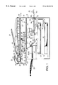
- FIG. 1 illustrates a sectional view of a copier-facsimile combined system according to the present invention
- FIG. 2 illustrates an enlarged sectional view of the system shown in FIG. 1;
- FIG. 3 is a circuit block diagram of the system shown in FIG. 1;
- FIG. 4 is a flowchart when the copier-facsimile system makes a copy on a recording sheet supplied from a flap-type paper tray;
- FIG. 5 schematically illustrates another copier-facsimile system.
- the present invention is embodied in a copier-facsimile system.
- a copier-facsimile system 11 includes a document feeding unit 12 , a document table 13 , a scanning unit 14 , a cut paper feeder 15 , a flap-type paper tray 16 , a recording unit 17 and a discharged cut paper tray 18 .
- the document feeder unit 12 includes an inclined built-in paper tray 22 for placing documents 21 , a separation roller 23 for feeding the documents 21 sheet by sheet, a plurality of feed roller 24 for transporting the document 21 along a predetermined path, a translucent plate 25 over which the document 21 passes, and a discharged document tray 26 for receiving discharged documents 21 .
- a document sensor 27 is provided in the paper tray 22 such that it faces the documents 21 on the paper tray 22 and outputs a detection signal if there is one or more documents 21 on the paper tray 22 .
- a discharged document sensor 28 is provided on a back surface of the upper paper tray 22 such that it faces the discharged document tray 26 and outputs a detection signal when a document 21 is discharged onto the tray 26 .
- the document table unit 13 includes a transparent document plate 31 to place the document 21 thereon and a pivotable lid or cover 32 to be placed over the document plate 31 .
- the document trays 22 and 26 of the document feeder unit 12 are mounted on the cover 32 of the document table unit 13 so that they move together with the cover 32 (they pivot about the same point as the cover 32 ).
- FIG. 1 illustrates the cover 32 placed on the document plate 31 (closed condition).
- the scanning unit 14 includes a light source 37 for emitting a light to the document 21 passing over the translucent plate 25 or the document 21 stationarily placed on the scanning bed 31 , first to third mirrors 38 to 40 for changing an optical path of a reflected light from the document 21 , and a moving mechanism 41 for moving the light source 37 and first to third mirrors 38 to 40 .
- the scanning unit 14 further includes a condensing lens 42 for condensing the light from the third mirror 40 and an image pick-up element (CCD) 43 for reading an image on the document 21 based on the light incoming through the condensing lens 42 .
- CCD image pick-up element
- the moving mechanism 41 includes a pair of right and left large pulleys 44 and 45 , a pair of right and left small pulleys 46 and 47 , a first belt 48 engaged over the large pulleys 44 and 45 , and a second belt 49 engaged over the small pulleys 46 and 47 .
- the moving mechanism 41 also includes a first carriage 50 connected to the first belt 48 , a second carriage 51 connected to the second belt 49 , and a step motor 52 .
- the large pulley 44 / 45 has a diameter twice as large as the small pulley 46 / 47 .
- the left large pulley 44 and small pulley 46 are coaxially united to each other and rotated together by the step motor 52 .
- the first carriage 50 supports the light source 37 and first mirror 38
- the second carriage 51 supports the second and third mirrors 39 and 40 .
- the first and second carriages 50 and 51 are moved via the first and second belts 48 and 49 .
- the first carriage 50 moves at a speed twice as fast as the second carriage 51 .
- the carriages 50 and 51 are selectively moved to an intermediate stand-by position P 1 , a first scanning position P 2 under the translucent plate 25 , or a second scanning start position P 3 under the right end 31 a of the scanning bed 31 .
- the document feeder unit 12 and scanning unit 14 constitute a means for automatically feeding a plurality of documents (ADF: Automatic Document Feeder).
- ADF Automatic Document Feeder
- the document table unit 13 and scanning unit 14 constitute a flat bed scanner (FBS). While the carriages 50 and 51 are being moved to the scanning end position P 4 from the second scanning start position P 3 , the image on the document 21 placed on the document plate 31 is scanned.
- a carriage sensor 53 is positioned below the right end 31 a of the document table 31 such that it outputs a detection signal when the carriages 50 and 51 are moved to the second scanning start position P 3 .
- the cut paper feeding unit 15 includes two paper cassettes 57 for accommodating cut paper 56 of different sizes in a stack condition, paper feed rollers 58 for feeding the cut paper 56 sheet by sheet along a predetermined path toward the recording unit 17 from the cassettes 57 , and guide plates 59 for guiding transportation of the cut paper 56 . It should be noted that two paper cassettes 57 are illustrated, but only one or more than two paper cassettes may be provided.
- the flap tray unit 16 includes a paper supporting plate 63 for holding sheets 62 thereon and a feed roller 64 for supplying the sheets 62 one by one from the supporting plate 63 toward the recording unit 17 via the upper guide plates 59 .
- the sheets 62 are loaded on the supporting plate 63 by a user's hand.
- a sheet sensor 65 is provided below the feed roller 64 such that it faces the sheet 62 when the sheet is placed on the supporting plate 63 .
- the sheet sensor 65 outputs a detection signal (ON signal) if there is one or more sheets 62 on the supporting plate 63 and an OFF signal when there is no recording sheet 62 .
- the recording unit 17 includes a photosensitive drum 68 , an electric charger 69 for uniformly charging a surface of the photosensitive drum 68 to a predetermined voltage, an exposing unit 70 for forming an electrostatic latent image on the photosensitive drum 68 , and a developing unit 71 for feeding a toner to the electrostatic latent image on the photosensitive drum 68 to develop the latent image in the form of toner image.
- the recording unit 17 also includes feed rollers 72 for feeding the cut paper 56 or sheet 62 to the photosensitive drum 68 , a transfer unit 73 for transferring the toner image onto the cut paper 56 or sheet 62 from the photosensitive drum 68 , and a fixer 74 for heating and fixing the toner image on the cut paper 56 or sheet 62 .
- the cut paper discharge unit 18 includes outlet rollers 77 for discharging the cut paper 56 or sheet 62 after recording, guide plates 78 for guiding movement of the paper 56 or sheet 62 , and a discharged paper tray 79 for receiving the discharged paper 56 or sheet 62 .
- FIG. 2 illustrates an enlarged view of the document feeding unit 12 , document table 13 and scanning unit 14 in cross section.
- the recording unit 17 is simply represented by the dotted line block in this illustration.
- CPU 82 controls movements of various components of the system 11 .
- ROM 83 stores control programs needed for CPU to function appropriately as a controller.
- RAM 84 temporarily stores data and the like as obtained during execution of the control programs.
- CPU 82 , ROM 83 and RAM 84 constitute a control means.
- RAM 84 constitutes a storage means.
- RAM 84 includes first to third memories 84 a , 84 b and 84 c .
- the first memory 84 a stores a size of a recording sheet 62 hand-loaded onto the flap-type paper tray 63 for reproducing of facsimile image data sent from a remote facsimile machine.
- the second memory 84 b stores a size of a recording sheet 62 which is also manually placed on the flap-type paper tray 63 for making a copy.
- the third memory 84 c stores a size of a recording sheet according to which the recording unit 17 operates when a recording sheet is supplied to the recording unit 17 from the flap-type paper tray 63 . Data to be stored in the third memory 84 c is supplied from the first or second memory 84 a or 84 b.
- the land-loaded sheet sensor 65 outputs a detection signal to CPU 82 .
- the scanning unit 14 scans an image on the original document 21 over the translucent plate 25 or scanning bed 31 and outputs a black and white binary image data to CPU 82 .
- An image memory 85 temporarily stores image data sent from the remote facsimile machine or image data scanned from the original by the scanning unit 14 .
- the recording unit 17 records the image data on the recording sheet 62 fed from the flap-type paper tray 63 or the cut paper 56 fed from the cassette 57 .
- a display 86 includes a liquid crystal display panel and/or LEDs and indicates various information about the operation mode of the system 11 such as “COPY MODE”, “FAX MODE”, “RECORDING SHEET CHANGED ?”, “STAND-BY CONDITION” and “SYSTEM FAILURE”.
- An control panel 87 includes various operation keys such as copy/fax key 87 a , start key 87 b and paper size input key 87 c.
- the copy/fax key 87 a is pressed to selectively perform a copy operation or facsimile operation.
- the start key 87 b is pressed to start the copy operation or facsimile operation.
- the paper size input key 87 c is an input means.
- the user when the user makes a copy of an original document by supplying a recording sheet 62 from the flap-type paper tray 16 , the user also inputs the paper size of the sheet 62 (second paper size for copy) using the input key 87 c .
- the first paper size is input at the beginning, and the second paper size setting is automatically switched to the first paper setting after making a copy. Therefore, the user inputs the first paper size only once, i.e., at the initial system setting and inputs the second paper size every time the user wants to have a copy using the flap-type paper tray 16 (described hereinafter).
- a modem 88 modulates and demodulates data to be transmitted to and received from a remote facsimile machine.
- NCU 89 controls connection and disconnection of a telephone line L 1 with and from the system 11 .
- NCU 89 also detects a dial pulse corresponding to a facsimile number of the remote facsimile. The dial pulse is sent to and received from the remote facsimile.
- CPU 82 When the user enters the first paper size using the input key 87 c , CPU 82 causes the first memory 84 a of RAM 84 to store the input paper size. When the user wants to have a copy printed on the sheet 62 and enters the second paper size using the input key 87 c , CPU 82 causes the second memory 84 b to store the input paper size.
- CPU 82 compares the paper size for copying with the paper size for facsimile data reproduction. If these sizes are not equal to each other (e.g., if the first paper size is A4 and the second paper size is B5), CPU 82 causes the display 86 to indicate a message such as “PAPER CHANGED ?”, thereby urging the user to change the paper size.
- CPU 82 allows the recording unit 17 and associated components to start the copy operation only when it receives ON, OFF and ON signals sequentially from the recording sheet sensor 65 after displaying the message on the display 86 if the first and second paper sizes are not the same.
- a series of ON, OFF and ON signals indicate that the user has taken a recording sheet of first size from the tray 16 and substitutes it with a recording sheet of second size which is appropriate for copying. In other words, this series of signals indicate completion of paper size change.
- CPU 82 compares the recording sheet size stored in the first memory 84 a and that stored in the second memory 84 b again when the copying is finished. If the former does not coincides with the latter, CPU 82 causes the display 86 to indicate the “PAPER CHANGED ?” message again. This is because the system 11 should prepare for facsimile data reception after copying.
- CPU 82 changes the paper size setting to that of the first memory 84 a from that of the second memory 84 b if it receives ON, OFF and ON signals sequentially from the recording sheet sensor 65 after displaying the paper change message. The series of ON, OFF and ON signals indicate completion of the paper size being switched back to A4 (fax size) from B5 (copy size).
- CPU 82 refers to the first memory 84 a when returning the paper size setting to the initial setting.
- the user inputs a paper size for facsimile data reproduction (e.g., A4) using the paper size input key 87 c of the control panel 87 . Then, this paper size is stored in the first memory 84 a of RAM 84 (S 1 ). The paper size data in the first memory 84 a is also stored in the third memory 84 c (S 2 ). The data in the third memory determines the operation of the recording unit 17 .
- the A4 size recording sheet is loaded on the flap-type paper tray 16 at the beginning.
- the recording unit operates according to the paper size data stored in the third memory 84 c and the facsimile image data sent from a remote facsimile is printed on the sheet 62 (S 4 ). Subsequent to this recording, the program proceeds to END.
- the system awaits the entering of the paper size for copying by the user.
- the paper size data is stored in the second memory 84 b of RAM 84 (S 5 ).
- the paper size data stored in the second memory 84 b is compared with the paper size date stored in the first memory 84 a (S 6 ).
- the display 86 indicates a message which urges the user to change the size of the recording sheet 62 such as “PAPER CHANGED ?” (S 7 ). Noticing this message, the user takes the A4 size recording sheet 62 from the flap-type paper tray 63 and inserts a B5 size recording sheet 62 . Following this paper replacement, the user presses a YES key to send a confirmation signal to CPU 82 (S 8 ).
- the paper sensor 65 outputs a series of ON, OFF and ON signals to CPU 82 as the user replaces the recording sheet 62 on the flap-type paper tray 63 . If CPU receives this series of signals from the paper sensor 65 (S 9 ), it determines that the recording sheet 62 has been switched to an appropriate size. When the user takes the A4 size recording sheet from the flap-type paper tray 63 , the detection signal of the paper sensor 65 changes from ON to OFF. Subsequent to this, when a new recording sheet (B5 sheet) is placed on the flap-type paper tray 63 , the detection signal of the paper sensor 65 changes from OFF to ON.
- the paper size data in the second memory 84 b is transferred to the third memory 84 c (S 10 ) so that the recording unit 17 operates according to the B5 size setting.
- the program bypasses S 7 to S 9 and jumps to S 10 .
- the user places the original 21 on the document tray 22 of the document feeder unit 12 or the scanning table 31 and presses the start key 87 b (S 11 ). Then, the scanning unit 14 scans an image or picture on the original 21 and the recording unit 17 prints the image data on the B5 recording sheet 62 (S 12 ).
- the user removes the B5 recording sheet (copy sheet) from the flap-type paper tray 63 and replaces it with an A4 recording sheet (facsimile data printing sheet) and presses YES key (S 15 ) to send a confirmation signal to CPU 82 .
- CPU 82 receives a series of ON, OFF and ON signals from the paper sensor 65 (S 16 ). As described above, this series of signals indicates completion of paper changing.
- the paper size data stored in the first memory 84 a is automatically transferred to the third memory 84 c (S 17 ).
- the program bypasses S 14 to S 16 and advances to S 17 .
- the system 11 is now ready for reception of facsimile image data or it is brought into a stand-by condition (S 18 ).
- the recording paper size for facsimile data reproduction is first entered by using the paper size input key 87 c and stored in the first memory 84 a of RAM 84 . After that, if the user enters a different paper size for copying and makes a copy of the original document 21 using the flap tray unit 16 , CPU 82 automatically returns the paper size setting to the initial condition after copying (S 12 ⁇ S 17 ). In other words, the recording paper size setting of the recording unit 17 is changed to the paper size stored in the first memory 84 a after the copy operation is finished under the control of CPU 82 . Therefore, the user does not need to re-input the paper size for facsimile data reproduction every time the user makes a copy using the flap-type paper tray unit 16 .
- CPU 82 compares this paper size with the paper size for facsimile data reproduction. If these sizes do not coincide with each other, the display 86 prompts the user to change the paper. In other words, if the user makes a copy using a paper size different from the facsimile data reproduction, the system 11 informs the user of necessity of paper change. Accordingly, it is possible to prevent that a copying is conducted onto an inappropriate size of recording sheet.
- the display 86 indicates a paper change message. However, the user might not see this message and might not replace the recording sheet 62 on the flap-type paper tray 63 . In this case, CPU 82 does not allow the recording unit 17 to perform the copying operation. The recording unit 17 is caused to make a copy only when CPU 82 receives a particular series of signals from the paper sensor 87 c which indicates switching of the recording sheet. Thus, copying on the recording sheet 62 is always carried out on an appropriately sized sheet of paper.
- the determination steps of S 8 and S 15 in the flowchart shown in FIG. 4 may be dispensed with.
- CPU 82 may determine the substitution of the recording sheet by the determination steps of S 9 and S 16 only.
- the message “PAPER CHANGED ?” is displayed in the display unit 86 at S 7 and S 14 , but other messages or particular signs or symbols may be displayed instead, or a certain sound may be made.
- the paper cassettes may not be incorporated in a body of the facsimile-copier system 11 , but they may partly extend from the lateral wall of the body of the facsimile-copier system such that an upper surface of the upper-most paper cassette 57 ′ may define a flap-type paper tray 16 as illustrated in FIG. 5 .
Landscapes
- Engineering & Computer Science (AREA)
- Multimedia (AREA)
- Signal Processing (AREA)
- Physics & Mathematics (AREA)
- General Physics & Mathematics (AREA)
- Facsimiles In General (AREA)
- Control Or Security For Electrophotography (AREA)
- Sheets, Magazines, And Separation Thereof (AREA)
- Facsimile Scanning Arrangements (AREA)
Applications Claiming Priority (2)
| Application Number | Priority Date | Filing Date | Title |
|---|---|---|---|
| JP7344697A JP3596223B2 (ja) | 1997-03-26 | 1997-03-26 | 複写機能付き通信端末装置 |
| JP9-073446 | 1997-03-26 |
Publications (1)
| Publication Number | Publication Date |
|---|---|
| US6198548B1 true US6198548B1 (en) | 2001-03-06 |
Family
ID=13518468
Family Applications (1)
| Application Number | Title | Priority Date | Filing Date |
|---|---|---|---|
| US09/047,071 Expired - Lifetime US6198548B1 (en) | 1997-03-26 | 1998-03-24 | Communication terminal device having copying function |
Country Status (6)
| Country | Link |
|---|---|
| US (1) | US6198548B1 (ja) |
| EP (1) | EP0868067B1 (ja) |
| JP (1) | JP3596223B2 (ja) |
| KR (1) | KR100372003B1 (ja) |
| DE (1) | DE69816896T2 (ja) |
| TW (1) | TW432858B (ja) |
Cited By (6)
| Publication number | Priority date | Publication date | Assignee | Title |
|---|---|---|---|---|
| US20010038463A1 (en) * | 1999-11-30 | 2001-11-08 | Katsutoshi Ishikawa | Image forming device |
| US20030231359A1 (en) * | 2002-06-14 | 2003-12-18 | Fuji Xerox Co., Ltd. | Image processing apparatus and paper feed control method |
| US20040190088A1 (en) * | 2003-03-31 | 2004-09-30 | Masataka Kakuta | Image-reading device |
| US20060176531A1 (en) * | 2000-12-22 | 2006-08-10 | Nozomi Sawada | Image forming apparatus, image forming method and computer-readable storage medium |
| US20070097393A1 (en) * | 2005-10-25 | 2007-05-03 | Brother Kogyo Kabushiki Kaisha | Image forming apparatus |
| US20170251119A1 (en) * | 2016-02-29 | 2017-08-31 | Fuji Xerox Co., Ltd. | Non-transitory computer readable medium, information processing method and information processing apparatus |
Families Citing this family (3)
| Publication number | Priority date | Publication date | Assignee | Title |
|---|---|---|---|---|
| US7268897B1 (en) | 1999-06-28 | 2007-09-11 | Canon Kabushiki Kaisha | Print control apparatus and method |
| US7151620B2 (en) | 2001-10-22 | 2006-12-19 | Hewlett-Packard Development Company, L.P. | Utility document lid for imaging devices |
| JP4635579B2 (ja) * | 2004-01-06 | 2011-02-23 | 富士ゼロックス株式会社 | 画像形成装置 |
Citations (9)
| Publication number | Priority date | Publication date | Assignee | Title |
|---|---|---|---|---|
| US4809050A (en) | 1986-09-11 | 1989-02-28 | Minolta Camera Kabushiki Kaisha | Copying machine for forming an image of a document at various magnifications |
| EP0391632A2 (en) | 1989-04-03 | 1990-10-10 | Sharp Kabushiki Kaisha | Sheet feeding device for facsimile apparatus |
| US5125636A (en) | 1989-01-30 | 1992-06-30 | Minolta Camera Kabushiki Kaisha | Copying machine capable of copying two originals on one sheet of paper |
| JPH04255872A (ja) | 1991-02-08 | 1992-09-10 | Fuji Xerox Co Ltd | 画像記録装置の自動用紙選択方式 |
| JPH06148990A (ja) | 1992-11-10 | 1994-05-27 | Canon Inc | 複写装置 |
| JPH089096A (ja) | 1994-06-17 | 1996-01-12 | Fuji Xerox Co Ltd | 画像形成装置の給紙システム |
| US5581344A (en) | 1994-03-16 | 1996-12-03 | Ricoh Company, Ltd. | Image forming apparatus with copy sheet size inputting and detection and corresponding selection of a copy sheet cassette |
| US5828465A (en) * | 1994-08-22 | 1998-10-27 | Minolta Co., Ltd. | Facsimile apparatus |
| US5917616A (en) * | 1995-09-29 | 1999-06-29 | Canon Kabushiki Kaisha | Image processing apparatus and control method thereof |
-
1997
- 1997-03-26 JP JP7344697A patent/JP3596223B2/ja not_active Expired - Fee Related
-
1998
- 1998-02-13 TW TW087102016A patent/TW432858B/zh not_active IP Right Cessation
- 1998-03-24 US US09/047,071 patent/US6198548B1/en not_active Expired - Lifetime
- 1998-03-25 DE DE69816896T patent/DE69816896T2/de not_active Expired - Lifetime
- 1998-03-25 EP EP98105438A patent/EP0868067B1/en not_active Expired - Lifetime
- 1998-03-26 KR KR10-1998-0010460A patent/KR100372003B1/ko not_active IP Right Cessation
Patent Citations (9)
| Publication number | Priority date | Publication date | Assignee | Title |
|---|---|---|---|---|
| US4809050A (en) | 1986-09-11 | 1989-02-28 | Minolta Camera Kabushiki Kaisha | Copying machine for forming an image of a document at various magnifications |
| US5125636A (en) | 1989-01-30 | 1992-06-30 | Minolta Camera Kabushiki Kaisha | Copying machine capable of copying two originals on one sheet of paper |
| EP0391632A2 (en) | 1989-04-03 | 1990-10-10 | Sharp Kabushiki Kaisha | Sheet feeding device for facsimile apparatus |
| JPH04255872A (ja) | 1991-02-08 | 1992-09-10 | Fuji Xerox Co Ltd | 画像記録装置の自動用紙選択方式 |
| JPH06148990A (ja) | 1992-11-10 | 1994-05-27 | Canon Inc | 複写装置 |
| US5581344A (en) | 1994-03-16 | 1996-12-03 | Ricoh Company, Ltd. | Image forming apparatus with copy sheet size inputting and detection and corresponding selection of a copy sheet cassette |
| JPH089096A (ja) | 1994-06-17 | 1996-01-12 | Fuji Xerox Co Ltd | 画像形成装置の給紙システム |
| US5828465A (en) * | 1994-08-22 | 1998-10-27 | Minolta Co., Ltd. | Facsimile apparatus |
| US5917616A (en) * | 1995-09-29 | 1999-06-29 | Canon Kabushiki Kaisha | Image processing apparatus and control method thereof |
Cited By (15)
| Publication number | Priority date | Publication date | Assignee | Title |
|---|---|---|---|---|
| US7133150B2 (en) * | 1999-11-30 | 2006-11-07 | Sharp Kabushiki Kaisha | Image forming device for image output form control |
| US20010038463A1 (en) * | 1999-11-30 | 2001-11-08 | Katsutoshi Ishikawa | Image forming device |
| US8730513B2 (en) | 2000-12-22 | 2014-05-20 | Ricoh Company, Ltd. | Image forming apparatus, and method for forming images on recording media such as paper having different sizes |
| US20060176531A1 (en) * | 2000-12-22 | 2006-08-10 | Nozomi Sawada | Image forming apparatus, image forming method and computer-readable storage medium |
| US8179559B2 (en) | 2000-12-22 | 2012-05-15 | Ricoh Company, Ltd. | Image forming apparatus with a substitute recording medium for an unavailable recording medium and method thereof |
| US8760711B2 (en) | 2000-12-22 | 2014-06-24 | Ricoh Company, Ltd. | Image forming apparatus, method, and computer-readable storage medium for forming images on recording media such as paper having different sizes |
| US9224078B2 (en) | 2000-12-22 | 2015-12-29 | Ricoh Company, Ltd. | Image forming apparatus, method, and computer-readable storage medium for forming images on recording media such as paper having different sizes |
| US9607252B2 (en) | 2000-12-22 | 2017-03-28 | Ricoh Company, Ltd. | Image processing apparatus, image forming system, and printing method that decide whether to store, print and not store, or print and store image data |
| US10115043B2 (en) | 2000-12-22 | 2018-10-30 | Ricoh Company, Ltd. | Image processing apparatus, image forming system, and printing method that decide whether to store, print and not store, or print and store image data |
| US20030231359A1 (en) * | 2002-06-14 | 2003-12-18 | Fuji Xerox Co., Ltd. | Image processing apparatus and paper feed control method |
| US20040190088A1 (en) * | 2003-03-31 | 2004-09-30 | Masataka Kakuta | Image-reading device |
| US7605955B2 (en) * | 2003-03-31 | 2009-10-20 | Fujinon Corporation | Image-reading device |
| US20070097393A1 (en) * | 2005-10-25 | 2007-05-03 | Brother Kogyo Kabushiki Kaisha | Image forming apparatus |
| US8009331B2 (en) * | 2005-10-25 | 2011-08-30 | Brother Kogyo Kabushiki Kaisha | Image forming apparatus |
| US20170251119A1 (en) * | 2016-02-29 | 2017-08-31 | Fuji Xerox Co., Ltd. | Non-transitory computer readable medium, information processing method and information processing apparatus |
Also Published As
| Publication number | Publication date |
|---|---|
| JP3596223B2 (ja) | 2004-12-02 |
| TW432858B (en) | 2001-05-01 |
| DE69816896T2 (de) | 2004-07-15 |
| DE69816896D1 (de) | 2003-09-11 |
| EP0868067A3 (en) | 1999-01-13 |
| KR19980080698A (ko) | 1998-11-25 |
| JPH10271269A (ja) | 1998-10-09 |
| EP0868067B1 (en) | 2003-08-06 |
| KR100372003B1 (ko) | 2004-06-04 |
| EP0868067A2 (en) | 1998-09-30 |
Similar Documents
| Publication | Publication Date | Title |
|---|---|---|
| US6198548B1 (en) | Communication terminal device having copying function | |
| US6057944A (en) | Image scanning device | |
| US5978614A (en) | Image scanning apparatus with light source condition testing | |
| JPH1195504A (ja) | 記録装置 | |
| US5585943A (en) | Complex recording apparatus | |
| JPH10271282A (ja) | 画像読取装置 | |
| JPH10285347A (ja) | 通信端末装置 | |
| JP3275815B2 (ja) | 画像形成装置 | |
| JP3840775B2 (ja) | 通信端末装置 | |
| JP3596222B2 (ja) | 画像読取装置 | |
| JP2002060089A (ja) | 画像形成装置 | |
| JP3533840B2 (ja) | 画像記録装置 | |
| JP3125737B2 (ja) | 画像読取装置 | |
| JP3562201B2 (ja) | 画像読取蓄積装置 | |
| JP3097604B2 (ja) | 通信機能付き記録装置 | |
| JP3591204B2 (ja) | 画像読取装置 | |
| JPH11112739A (ja) | 読取装置 | |
| JPH10276307A (ja) | 複写装置 | |
| JPH10285349A (ja) | 画像読取記録装置 | |
| JPH1155469A (ja) | 通信端末装置 | |
| JPH10285346A (ja) | 画像読取記録装置 | |
| JPH1169054A (ja) | 複写機能付き通信端末装置 | |
| JPH1169030A (ja) | 複写機能付き通信端末装置 | |
| JPH11205539A (ja) | 画像読取装置 | |
| JP2000041141A (ja) | 画像処理装置 |
Legal Events
| Date | Code | Title | Description |
|---|---|---|---|
| AS | Assignment |
Owner name: MURATA KIKAI KABUSHIKI KAISHA, JAPAN Free format text: ASSIGNMENT OF ASSIGNORS INTEREST;ASSIGNORS:YOSHIKAWA, HIROYASU;SONEOKA, TAKU;REEL/FRAME:009105/0816 Effective date: 19980316 |
|
| STCF | Information on status: patent grant |
Free format text: PATENTED CASE |
|
| FPAY | Fee payment |
Year of fee payment: 4 |
|
| FEPP | Fee payment procedure |
Free format text: PAYOR NUMBER ASSIGNED (ORIGINAL EVENT CODE: ASPN); ENTITY STATUS OF PATENT OWNER: LARGE ENTITY Free format text: PAYER NUMBER DE-ASSIGNED (ORIGINAL EVENT CODE: RMPN); ENTITY STATUS OF PATENT OWNER: LARGE ENTITY |
|
| FPAY | Fee payment |
Year of fee payment: 8 |
|
| FPAY | Fee payment |
Year of fee payment: 12 |