US6163093A - Pump actuation motor for automotive antilock brake system - Google Patents
Pump actuation motor for automotive antilock brake system Download PDFInfo
- Publication number
- US6163093A US6163093A US09/503,734 US50373400A US6163093A US 6163093 A US6163093 A US 6163093A US 50373400 A US50373400 A US 50373400A US 6163093 A US6163093 A US 6163093A
- Authority
- US
- United States
- Prior art keywords
- yoke
- rotation shaft
- supported
- end side
- motor
- Prior art date
- Legal status (The legal status is an assumption and is not a legal conclusion. Google has not performed a legal analysis and makes no representation as to the accuracy of the status listed.)
- Expired - Lifetime
Links
Images


Classifications
-
- F—MECHANICAL ENGINEERING; LIGHTING; HEATING; WEAPONS; BLASTING
- F16—ENGINEERING ELEMENTS AND UNITS; GENERAL MEASURES FOR PRODUCING AND MAINTAINING EFFECTIVE FUNCTIONING OF MACHINES OR INSTALLATIONS; THERMAL INSULATION IN GENERAL
- F16C—SHAFTS; FLEXIBLE SHAFTS; ELEMENTS OR CRANKSHAFT MECHANISMS; ROTARY BODIES OTHER THAN GEARING ELEMENTS; BEARINGS
- F16C35/00—Rigid support of bearing units; Housings, e.g. caps, covers
- F16C35/04—Rigid support of bearing units; Housings, e.g. caps, covers in the case of ball or roller bearings
- F16C35/06—Mounting or dismounting of ball or roller bearings; Fixing them onto shaft or in housing
-
- B—PERFORMING OPERATIONS; TRANSPORTING
- B60—VEHICLES IN GENERAL
- B60T—VEHICLE BRAKE CONTROL SYSTEMS OR PARTS THEREOF; BRAKE CONTROL SYSTEMS OR PARTS THEREOF, IN GENERAL; ARRANGEMENT OF BRAKING ELEMENTS ON VEHICLES IN GENERAL; PORTABLE DEVICES FOR PREVENTING UNWANTED MOVEMENT OF VEHICLES; VEHICLE MODIFICATIONS TO FACILITATE COOLING OF BRAKES
- B60T8/00—Arrangements for adjusting wheel-braking force to meet varying vehicular or ground-surface conditions, e.g. limiting or varying distribution of braking force
- B60T8/32—Arrangements for adjusting wheel-braking force to meet varying vehicular or ground-surface conditions, e.g. limiting or varying distribution of braking force responsive to a speed condition, e.g. acceleration or deceleration
- B60T8/34—Arrangements for adjusting wheel-braking force to meet varying vehicular or ground-surface conditions, e.g. limiting or varying distribution of braking force responsive to a speed condition, e.g. acceleration or deceleration having a fluid pressure regulator responsive to a speed condition
- B60T8/40—Arrangements for adjusting wheel-braking force to meet varying vehicular or ground-surface conditions, e.g. limiting or varying distribution of braking force responsive to a speed condition, e.g. acceleration or deceleration having a fluid pressure regulator responsive to a speed condition comprising an additional fluid circuit including fluid pressurising means for modifying the pressure of the braking fluid, e.g. including wheel driven pumps for detecting a speed condition, or pumps which are controlled by means independent of the braking system
- B60T8/4018—Pump units characterised by their drive mechanisms
- B60T8/4022—Pump units driven by an individual electric motor
-
- F—MECHANICAL ENGINEERING; LIGHTING; HEATING; WEAPONS; BLASTING
- F04—POSITIVE - DISPLACEMENT MACHINES FOR LIQUIDS; PUMPS FOR LIQUIDS OR ELASTIC FLUIDS
- F04B—POSITIVE-DISPLACEMENT MACHINES FOR LIQUIDS; PUMPS
- F04B17/00—Pumps characterised by combination with, or adaptation to, specific driving engines or motors
- F04B17/03—Pumps characterised by combination with, or adaptation to, specific driving engines or motors driven by electric motors
-
- F—MECHANICAL ENGINEERING; LIGHTING; HEATING; WEAPONS; BLASTING
- F04—POSITIVE - DISPLACEMENT MACHINES FOR LIQUIDS; PUMPS FOR LIQUIDS OR ELASTIC FLUIDS
- F04B—POSITIVE-DISPLACEMENT MACHINES FOR LIQUIDS; PUMPS
- F04B53/00—Component parts, details or accessories not provided for in, or of interest apart from, groups F04B1/00 - F04B23/00 or F04B39/00 - F04B47/00
- F04B53/10—Valves; Arrangement of valves
- F04B53/108—Valves characterised by the material
- F04B53/1082—Valves characterised by the material magnetic
-
- H—ELECTRICITY
- H02—GENERATION; CONVERSION OR DISTRIBUTION OF ELECTRIC POWER
- H02K—DYNAMO-ELECTRIC MACHINES
- H02K5/00—Casings; Enclosures; Supports
- H02K5/04—Casings or enclosures characterised by the shape, form or construction thereof
- H02K5/16—Means for supporting bearings, e.g. insulating supports or means for fitting bearings in the bearing-shields
- H02K5/173—Means for supporting bearings, e.g. insulating supports or means for fitting bearings in the bearing-shields using bearings with rolling contact, e.g. ball bearings
- H02K5/1732—Means for supporting bearings, e.g. insulating supports or means for fitting bearings in the bearing-shields using bearings with rolling contact, e.g. ball bearings radially supporting the rotary shaft at both ends of the rotor
-
- H—ELECTRICITY
- H02—GENERATION; CONVERSION OR DISTRIBUTION OF ELECTRIC POWER
- H02K—DYNAMO-ELECTRIC MACHINES
- H02K7/00—Arrangements for handling mechanical energy structurally associated with dynamo-electric machines, e.g. structural association with mechanical driving motors or auxiliary dynamo-electric machines
- H02K7/14—Structural association with mechanical loads, e.g. with hand-held machine tools or fans
Definitions
- the present invention relates to a pump actuation motor for an automotive antilock brake system.
- ABS antilock braking system
- the automotive ABS controls the braking torque so that wheel slip rate at the time of braking will be maintained within an appropriate range, whereby the automotive ABS is structured so as to output a maximum braking force at any time, even under a slippery circumstance where steering performance of the wheels is deteriorated, for instance, such as rain, snow or a gravel road.
- brake fluid can circulate within a hydraulic pressure circuit formed between a brake master cylinder that is so provided as to connect with a brake pedal for an automobile and wheel cylinders that are so provided as to connect with wheel brakes.
- an actuator which controls the hydraulic pressure by opening and closing normally-open solenoid valves and normally-closed solenoid valves that are disposed on the hydraulic pressure circuit that extends from the brake master cylinders to the wheel cylinders.
- the actions of the actuator are controlled by an electronic control unit that uses a microcomputer.
- the electronic control unit receives output on the travelling state of an automobile from such as wheel speed sensors that are provided on the wheels respectively.
- the electronic control unit controls the actuator with a command in any of these modes: a pressure increase mode where the braking torque.is increased by increasing the hydraulic pressure that is applied from the brake master cylinders to the wheel cylinders, a holding mode where the braking torque is held by preventing the hydraulic pressure transmission from the brake master cylinders to the wheel cylinders, and a pressure decrease mode where the braking torque is decreased by temporarily reserving the hydraulic pressure from the wheel cylinders at reservoirs (tanks) to prevent locking state at the wheels.
- a pressure increase mode where the braking torque.is increased by increasing the hydraulic pressure that is applied from the brake master cylinders to the wheel cylinders
- a holding mode where the braking torque is held by preventing the hydraulic pressure transmission from the brake master cylinders to the wheel cylinders
- a pressure decrease mode where the braking torque is decreased by temporarily reserving the hydraulic pressure from the wheel cylinders at reservoirs (tanks) to prevent locking state at the wheels.
- an hydraulic pump driving apparatus has been proposed on JP-A-9-323643, for instance.
- bearing holders are so formed in a cup shape as to expand in an axial direction at center parts of end walls respectively on the side of a housing that stores the hydraulic pump and on the side of a motor casing (a yoke).
- a motor rotation shaft is supported by fitting a ball bearing into such bearing holders.
- an electric-powered pump motor assembly on JP-W-8-510314.
- a barrel-shape bearing is so formed with a rivet at a bottom part of a motor housing (a yoke) as to support by fitting in a blind hole that is provided at one end of a rotation shaft of a motor.
- the barrel-shape bearing is a slide bearing that needs oil replenishment, such as greasing, there is a fear that the oil exploded out of the bearing might stick to a power feeding part to thereby cause a power feed failure and abnormal wear and thus that the durability would be deteriorated.
- the present invention is purposed to provide a pump actuation motor for an automotive antilock brake system, which can solve the above-described problems through downsizing by shortening the motor shaft length, improvement of coaxial accuracy of the yoke and the rotation shaft, increase in the assembling efficiency by decrease in the quantity of the parts and enhancement of the durability.
- the invention comprises the following structure for achievement of the above-described purpose.
- an automotive-antilock-brake-system pump actuation motor for actuation of a pump disposed in a hydraulic pressure circuit of an automotive antilock brake system comprises a yoke, a rotation shaft that has, on one-end side, a supported shaft portion that is inserted into and supported by a system main body and an eccentric shaft portion that actuates the pump and, on the other end side, a rotor and a commutator are attached, a brush holder that holds a brush that can supply electric power from the system main body side to the commutator, and a housing that is so mounted between the yoke and the system main body side as to cover an opening of such yoke.
- the rotation shaft has a recessed portion that opens on an end surface of the other end side, the yoke has a protruding portion that protrudes into the recessed portion that is formed as a part of such yoke, and the other end side of the rotation shaft is supported by such protruding portion.
- a slide bearing may be press-fitted between the protruding portion of the yoke and the recessed portion of the rotation shaft.
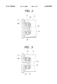
- FIG. 1 is a cross-sectional view showing an entire configuration of a pump actuation motor for an automotive antilock brake system
- FIG. 2 is an enlarged explanation view showing the support structure of the rotation shaft on the yoke side of part B in FIG. 1;
- FIG. 3 is an enlarged explanation view showning the support structure of the rotation shaft on the yoke side of part B in FIG. 1;
- FIG. 4 is a left side view of the pump actuation motor in FIG. 1;
- FIG. 5 is a right side view of the pump actuation motor in FIG. 1;
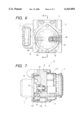
- FIG. 6 is a partly-cutout explanation view of the actuator
- FIG. 7 is a partly-cutout explanation view of the actuator viewed in a direction showed with arrows A--A in FIG. 6;
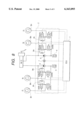
- FIG. 8 is a view showing a typical configuration of the automotive antilock brake system.
- An electronic control unit 1 controls the actions of the hydraulic pressure circuit that constitutes an actuator 2.
- Brake master cylinders M/C that produce brake fluid pressure from each of the cylinder chambers in accordance with the amount of depression on a brake pedal (not shown) is connected to the hydraulic pressure circuit inside the actuator 2.
- a left front wheel Fl, a right rear wheel Rr, a left rear wheel Rl and right front wheel Fr are respectively provided with wheel brakes B Fl , B Rr , B Rl and B Fr .
- the hydraulic pressure circuit of the actuator 2 is connected to wheel cylinders (not shown) that actuate the wheel brakes.
- the actuator 2 includes normally-open input valves IV (Fl) and IV (Rr) that connect to cylinders of the wheel brakes B Fl and B Rr and input valves IV (Rl) and IV (Fr) that connect to cylinders of the wheel brakes B Rl and B Fr respectively from the brake master cylinders M/C.
- normally-closed output valves OV (Fl), OV (Rr), OV (Rl) and OV (Fr) are respectively connected in parallel.
- the output valves OV (Fl) and OV (Rr) are connected to a reservoir 3 for temporary reserve of brake fluid and the output valves OV (Rl) and OV (Fr) are connected to a reservoir 4 for temporary reserve of brake fluid, respectively.
- the reservoirs 3 and 4 are connected to the inlets of plunger pumps 5 and 6, and such plunger pumps 5 and 6 circulate the brake fluid to return from the reservoirs 3 and 4 to the brake master cylinders M/C.
- the pump actuation motor 7 actuates the plunger pumps 5 and 6 through reciprocation of the pistons when the motor is driven to revolve as described below.
- the normally-open input valves IV (Fl), IV (Rr), IV (Rl) and IV (Fr) are opened and closed by solenoid valves that are driven with solenoids, and the opening and closing actions are controlled by the electronic control unit 1.
- the normally-closed output valves OV (Fl), OV (Rr), OV (Rl) and OV (Fr) are also opened and closed by solenoid valves that are driven with solenoids, and the opening and closing actions are controlled by the electronic control unit 1.
- Check valves 8 Fl , 8 Rr , 8 Rl and 8 Fr are respectively connected in parallel to the normally-open input valves IV (Fl), IV (Rr), IV (Rl) and IV (Fr), which are opened to return the brake fluid from the corresponding wheel brakes B Fl , B Rr , B Rl and B Fr to the brake master cylinders M/C after cancellation of input to such-brake master cylinders M/C.
- the electronic control unit 1 receives output on the travelling state of an automobile from such as wheel speed sensors (not shown) that are provided on the wheels Fl, Rr, Rl and Fr, respectively.
- the electronic control unit 1 controls the actuator 2 with a command to each of the wheel brakes B Fl , B Rr , B Rl and B Fr respectively in response to the travelling state of the automobile in any of a pressure increase mode, a holding mode and a pressure decrease mode.
- the braking torque is increased by respectively opening the normally-open input valves IV (Fl), IV (Rr), IV (Rl) and IV (Fr) and by closing the normally-closed output valves OV (Fl), OV (Rr), OV (Rl) and OV (Fr) so as to increase the hydraulic pressure that is applied to the wheel cylinders (not shown) from the brake master cylinders M/C.
- the braking torque is held by respectively closing the normally-open input valves IV (Fl), IV (Rr), IV (Rl) and IV (Fr) and the normally-closed output valves OV (Fl), OV (Rr), OV (Rl) and OV (Fr) so as to prevent the hydraulic pressure transmission from the brake master cylinders M/C to the wheel cylinders (not shown).
- the braking torque is decreased by respectively closing the normally-open input valves IV (Fl), IV (Rr), IV (Rl) and IV (Fr) and opening the normally-closed output valves OV (Fl), OV (Rr), OV (Rl) and OV (Fr) so as to temporarily reserve the hydraulic pressure from the wheel cylinders (not shown) at reservoirs 3 and 4 and to prevent locking state at the wheels.
- the electronic control unit 1 drives the pump actuation motor 7 to actuate the plunger pumps 5 and 6, so that the brake fluid temporarily reserved in the reservoirs 3 and 4 is returned to the side of the brake master cylinders M/C.
- a block body 9 that constitutes a system main body on which the actuation motor 7 is mounted is a metal body formed in shape of a block.
- the block body 9 is provided with the plunger pumps 5 and 6 (see FIG. 6) that is actuated by the pump actuation motor 7.
- the block body 9 there is attached thereon parts, such as the solenoids 10 that open and close the normally-open input valves IV (Fl), IV (Rr), IV (Rl) and IV (Fr) and the normally-closed output valves OV (Fl), OV (Rr), OV (Rl) and OV (Fr), and the electronic control unit 1 for control of actions of the actuator 2 (see FIG. 7).
- a connector 11 for power supply to the electronic control unit 1 is provided on the block body 9 (see FIG. 7).
- the pump ctuation motor 7 is mounted and secured in such a manner that a main-body-side end portion 13 being one end of the rotation shaft 12 is inserted within the block body 9 and a terminal 14 for supplying power to the pump actuation motor 7 is inserted into a connection terminal in the electronic control unit 1 (see FIG. 7).
- the pump actuation motor 7 utilizes an inner-rotor-type motor.
- FIG. 1 the structure of the stator of the motor is described first.
- a yoke 15 that is formed in a cup shape constitutes the exterior of the motor.
- the yoke 15 is preferably made of a metal material, such as a steel plate for deep drawing (SPCE).
- a plurality of arc-shaped magnets 16 (two in this embodiment) of a magnetic material, such as ferrite, are attached on the inner wall surface of the yoke 15 and magnetized in a necessary number of magnetic poles (quadrupoles in this embodiment).
- a projection 17 is formed on the inner wall surface of the yoke 15 along the axial direction in an inwardly expanded form.
- One end 16a of each the magnet 16 is abutted against either sides of the projection 17 while a U-shape clip 18 as an elastic member is elastically clamped between the other ends 16b of the magnets 16, so that the magnets 16 are securely mounted with mechanically intensified forces applied in the circumferential directions thereof.
- the magnets 16 are detachable when the clip 18 is removed and thus can be recycled.
- FIG. 1 The structure of a rotor of the motor is described now.
- a core 19 is fitted in the rotation shaft 12.
- An insulating material 20 coats around the core 19, and an armature winding (magnet wire) 21 is wound around the slot formed in the core 19.
- a commutator 22 is fitted on an end portion 27 on the rotor side being the other end of the rotation shaft 12 and energizes the armature winding 21 as to apply force on the rotor in the revolving direction.
- a brush holder 23 holds a brush 24 that can supply electric power to the commutator 22 on the rotor side from the block body 9 that is the system main body side.
- the brush 24 is so. applied with a force as to normally slidably contact with the commutator 22. That is, a spring 25 is mounted elastically between an inner surface of a raised fitting wall 23a of the brush holder 23 and the brush 24.
- the raised fitting wall 23a is fitted in an opening of the yoke 15 and, while the flange part 23b is thrust against a stepped portion 15c of the yoke 15, an outer flange wall 23c is thrust against an inner wall surface of a fitting part 26a of a housing 26 that is so fitted as to cover the opening of the yoke 15.
- the housing 26 is interposed between the yoke 15 and the block body 9 in such a manner that the fitting part 26a is so fitted on a raised stepped portion wall 15d as to cover the opening of the yoke 15.
- a shaft hole 26b for insertion of the rotation shaft 12 and a plurality of holes 26c for weight reduction are formed in the housing 26.
- One of the holes 26c is utilized as a hole for insertion of the terminal 14 for ensuring electric continuity to the electronic control unit 1 on the block body 9 side.
- a recessed portion 12a that opens at the other end thereof being the end surface of the rotor-side end portion 27.
- a protruding portion 15a that protrudes toward the inside of the recessed portion 12a and is formed as a part of the single piece of the yoke 15 by press working.
- the protruding portion 15a can support the rotor-side end portion 27 of the rotation shaft 12.
- the protruding portion 15a of the yoke 15 and the projection 17 formed on the inner wall surface of the yoke 15 is formed as a part of the single piece by a press working (squeezing process).
- a shaft-end ball bearing 28 is press-fitted as a rolling bearing between the protruding portion 15a of the yoke 15 and the recessed portion 12a of the rotation shaft 12.
- the rotorside end portion 27 can be supported to the protruding portion 15a that is formed as a part of the single piece of the yoke 15 and protrudes toward the inside of the recessed portion 12a that opens at the shaft end surface of the rotor-side end portion 27.
- the length of the rotation shaft 12 in the axial direction is reduced to thereby perform the compactification of the whole motor in the axial direction.
- the yoke 15 and the protruding portion 15a are formed in a single piece, the sealing material in the case of composition as the independent parts is not necessary.
- the protruding portion 15a can be formed to be coaxial with the rotation shaft 12 at the press working, the coaxial accuracy to the rotation shaft 12 can be improved.
- the press-fitting of the shaft-end ball bearing 28 between the protruding portion 15a of the yoke 15 and the recessed portion 12a of the rotation shaft 12 eliminates the oil replenishment, such as greasing, and accordingly eliminates the cause for power feed failure and abnormal wear by the oil exploded out of the bearing, and thus the durability of the motor can be enhanced.
- the shaft-end ball bearing 28 may be press-fitted into a recessed portion inner wall surface 12b of the rotation shaft 12 and so assembled as to form a little clearance between the bearing 28 and a protruding portion outer wall surface 15b of the protruding portion 15a as shown in FIG. 2. Further, the shaft-end ball bearing 28 may be press-fitted onto the protruding portion outer wall surface 15b of the protruding portion 15a and so assembled as to form a little clearance between the bearing and the recessed portion inner wall surface 12b of the rotation shaft 12 as shown in FIG. 3.
- the shaft-end ball bearing 28 is press-fitted into the recessed portion inner wall surface 12b of the rotation shaft 12 as shown in FIG. 2. The reason is that, if the bearing 28 is press-fitted onto the protruding portion 15a that is formed by press working, a tolerance in radial directions increases whereas the bearing is of a small size and thus a design standard for the load in the radial directions becomes severer.
- a supporting ball bearing 29 is press-fitted on the rotation shaft 12.
- the supporting ball bearing 29 is so press-fitted as to be accommodated between the brush holder 23 and the housing 26.
- the supporting ball bearing 29 receives radial-direction load that is applied on the rotation shaft 12 since the housing 26 that covers the outer circumference of the ball bearing 29 is press-fitted into and supported to the block body 9.
- An eccentric shaft portion 12c is formed in the vicinity of the main-body-side end portion 13 of the rotation shaft 12.
- An actuation ball bearing 30 is press-fitted on the eccentric shaft portion 12c.
- the actuation ball bearing 30 reciprocates pistons 5a and 6a of the plunger pumps 5 and 6 in cooperation with springs 5b and 6b (see FIG. 6).
- a supporting shaft portion 12d is formed on the main-body-side end portion 13 of the. rotation shaft 12.
- the supporting shaft portion 12d is press-fitted into and supported to the main-body-side ball-bearing 31 that is provided on the block body 9 side.
- the main-body-side end portion 13 of the rotation shaft 12 is press-fitted onto and supported to the block body 9 in such a manner that the supporting shaft portion 12d is press-fitted in and supported to the main-body-side ball bearing 31, and the supporting ball bearing 29 that is press-fitted on the rotation shaft 12 is supported to the block body 9 via the housing 26.
- the eccentric shaft portion 12c that actuates the plunger pumps 5 and 6 is formed at the main-body-side end portion 13, and the actuation ball bearing 30 is press-fitted on the eccentric shaft portion 12c.
- the commutator 22 and rotor are stored and attached inside the yoke 15.
- the rotor-side end portion 27 of the rotation shaft 12 is supported to the shaft-end ball bearing 28 that is press-fitted between the recessed portion 12a that opens at the shaft end face and the protruding portion 15a of the yoke 15.
- the main-body-side end portion 13 of the rotation shaft 12 is supported to the supporting ball bearing 29 and the main-body-side ball bearing 31 respectively in the vicinity of both sides of the actuation ball bearing 30 where large loads are applied in the radial directions while approximately no loads in the radial directions are applied at the rotor-side end portion 27.
- a small ball bearing as the end portion-supporting ball bearing 28.
- the main-body-side end portion 13 of the rotation shaft 12, which extends from the housing 26 of the pump actuation motor 7 is press-fitted into the main-body-side bearing 31 in the block body 9 and then the outer circumference of the housing 26 is sealed.
- the rotation shaft since it is possible that the rotor-side end portion is supported within the recessed portion that opens at the shaft end surface of the rotor-side end portion so that the protruding portion that is formed as one part of the single piece of the yoke protrudes toward inside of the recessed portion, the length of the rotation shaft in the axial direction is reduced to thereby perform the compactification of the whole motor in the axial direction. Since the yoke and the protruding portion are formed in a single piece, the sealing material in the case of composition as the independent parts is not necessary. Moreover, since the protruding portion can be formed to be coaxial with the rotation shaft at the press working, the coaxial accuracy to the rotation shaft can be improved.
- the press-fitting of the shaft-end ball bearing between the protruding portion of the yoke and the recessed portion of the rotation shaft eliminates the oil replenishment, such as greasing, and thus, eliminates the cause for power feed failure and abnormal wear by the oil exploded out of the bearing and the durability can be enhanced. Additionally, since the rotor-side end portion of the rotation shaft is supported by the rolling bearing that is press-fitted between the protruding portion of the yoke and the recessed portion of the rotation shaft, there is no need for clearance between the rotation shaft and the rolling bearing, and thus the loudness of the working motor sound can be reduced.
Landscapes
- Engineering & Computer Science (AREA)
- Mechanical Engineering (AREA)
- General Engineering & Computer Science (AREA)
- Power Engineering (AREA)
- Physics & Mathematics (AREA)
- Fluid Mechanics (AREA)
- Transportation (AREA)
- Regulating Braking Force (AREA)
- Connection Of Motors, Electrical Generators, Mechanical Devices, And The Like (AREA)
- Details Of Reciprocating Pumps (AREA)
- Motor Or Generator Frames (AREA)
- Valves And Accessory Devices For Braking Systems (AREA)
Applications Claiming Priority (2)
| Application Number | Priority Date | Filing Date | Title |
|---|---|---|---|
| JP11-079416 | 1999-03-24 | ||
| JP07941699A JP3725992B2 (ja) | 1999-03-24 | 1999-03-24 | 車両用アンチロックブレーキ装置のポンプ作動用モータ |
Publications (1)
| Publication Number | Publication Date |
|---|---|
| US6163093A true US6163093A (en) | 2000-12-19 |
Family
ID=13689278
Family Applications (1)
| Application Number | Title | Priority Date | Filing Date |
|---|---|---|---|
| US09/503,734 Expired - Lifetime US6163093A (en) | 1999-03-24 | 2000-02-15 | Pump actuation motor for automotive antilock brake system |
Country Status (4)
| Country | Link |
|---|---|
| US (1) | US6163093A (de) |
| EP (1) | EP1038745B1 (de) |
| JP (1) | JP3725992B2 (de) |
| DE (1) | DE60011168T2 (de) |
Cited By (12)
| Publication number | Priority date | Publication date | Assignee | Title |
|---|---|---|---|---|
| US20010033113A1 (en) * | 2000-04-10 | 2001-10-25 | Tadashi Takano | Rotating electrical machine |
| US6509661B1 (en) * | 1999-01-14 | 2003-01-21 | Asmo Co., Ltd. | Motor and actuator |
| US20030035716A1 (en) * | 2001-08-20 | 2003-02-20 | Tomohide Tanaka | Pump actuation motor |
| US6534889B2 (en) * | 1999-12-17 | 2003-03-18 | Sankyo Seiki Mfg. Co., Ltd. | Motor with rotator having shaft insertion sections with different internal peripheral surfaces |
| US6717299B2 (en) | 2001-10-30 | 2004-04-06 | Robert Bosch Corporation | Isolation system for a motor |
| US20040075352A1 (en) * | 2001-01-18 | 2004-04-22 | Gerd Hartel | Motor-pump assembly, in particular an anti-lock braking system for a motor vehicle |
| US20050207914A1 (en) * | 2004-03-19 | 2005-09-22 | Siemens Aktiengesellschaft | Motor pump assembly |
| US20080174192A1 (en) * | 2005-05-13 | 2008-07-24 | Continental Teves Ag & Co. Ohg | Electrohydraulic Aggregate with a Compact Construction |
| CN102201716A (zh) * | 2011-06-03 | 2011-09-28 | 蒂森克虏伯机场系统(中山)有限公司 | 一种筒式摆动减速电机装置 |
| US10938264B2 (en) * | 2017-10-13 | 2021-03-02 | Wei Zhu | Motor housing made of titanium |
| US11661065B2 (en) | 2018-09-07 | 2023-05-30 | Nissan Motor Co., Ltd. | Vehicle travel control method and vehicle travel control apparatus |
| US20230296112A1 (en) * | 2022-03-15 | 2023-09-21 | Walrus Pump Co., Ltd. | Motor module and motor module comprising the same |
Families Citing this family (8)
| Publication number | Priority date | Publication date | Assignee | Title |
|---|---|---|---|---|
| US6945757B2 (en) | 2001-01-18 | 2005-09-20 | Siemens Aktiengesellschaft | Motor pump unit, particularly a motor vehicle braking device |
| JP2007236144A (ja) * | 2006-03-02 | 2007-09-13 | Kokusan Denki Co Ltd | 電動機 |
| DE102008007720B4 (de) * | 2008-02-06 | 2016-06-09 | Brose Fahrzeugteile GmbH & Co. Kommanditgesellschaft, Würzburg | Elektromotorischer Antrieb |
| CN101885325A (zh) * | 2009-05-12 | 2010-11-17 | 德昌电机(深圳)有限公司 | 一种防抱死制动系统及其电机 |
| DE102012222281A1 (de) * | 2012-12-05 | 2014-06-05 | Robert Bosch Gmbh | Andrehvorrichtung und Verfahren zur Herstellung und/oder Montage einer axialspielreduzierten Lagerung einer Ankerwelle einer Andrehvorrichtung |
| JP6209127B2 (ja) * | 2014-05-13 | 2017-10-04 | 本田技研工業株式会社 | モータ構造体 |
| KR102411378B1 (ko) * | 2015-09-18 | 2022-06-22 | 엘지이노텍 주식회사 | 모터 및 이를 포함하는 브레이크 장치 |
| DE102019107511A1 (de) | 2018-06-20 | 2019-12-24 | Hanon Systems | Vorrichtung zum Antreiben eines Verdichters und Verfahren zum Montieren der Vorrichtung |
Citations (4)
| Publication number | Priority date | Publication date | Assignee | Title |
|---|---|---|---|---|
| US4797762A (en) * | 1987-09-22 | 1989-01-10 | Micropolis Corporation | Stress free winchester drive shaft mounting |
| US5555211A (en) * | 1995-01-23 | 1996-09-10 | Quantum Corporation | Improved spindle shaft for attaching a cover in a disk drive |
| JPH08510314A (ja) * | 1993-05-12 | 1996-10-29 | アイティーティー・オートモーティブ・ヨーロップ・ゲーエムベーハー | 電動ポンプモータ組立体 |
| JPH09323643A (ja) * | 1996-06-06 | 1997-12-16 | Kokusan Denki Co Ltd | アンチロックブレーキ制御装置の油圧ポンプ駆動装置 |
Family Cites Families (8)
| Publication number | Priority date | Publication date | Assignee | Title |
|---|---|---|---|---|
| BE421375A (de) * | ||||
| DE4430909A1 (de) * | 1994-08-31 | 1996-03-07 | Bosch Gmbh Robert | Einheit aus Antriebsmotor und Radialkolbenpumpe |
| DE4444646A1 (de) * | 1994-12-15 | 1996-06-20 | Teves Gmbh Alfred | Kolbenpumpe |
| DE4445362A1 (de) * | 1994-12-20 | 1996-06-27 | Bosch Gmbh Robert | Kolbenpumpe |
| US5644180A (en) * | 1995-06-06 | 1997-07-01 | Itt Automotive Electrical Systems, Inc. | Rear motor bearing for worm gear drive motors |
| EP0861516A1 (de) * | 1995-11-14 | 1998-09-02 | Itt Automotive, Inc. | Lageranordnung für einen elektromotor mit einer kontaktfläche zur orientierung des lagers an die statorinnenfläche innerhalb des stators |
| DE19654352A1 (de) * | 1996-12-24 | 1998-06-25 | Bosch Gmbh Robert | Kollektormaschine mit Gehäusekontaktierung |
| DE19813301A1 (de) * | 1998-03-26 | 1999-09-30 | Bosch Gmbh Robert | Pumpeneinheit |
-
1999
- 1999-03-24 JP JP07941699A patent/JP3725992B2/ja not_active Expired - Fee Related
-
2000
- 2000-02-08 DE DE60011168T patent/DE60011168T2/de not_active Expired - Lifetime
- 2000-02-08 EP EP00102155A patent/EP1038745B1/de not_active Expired - Lifetime
- 2000-02-15 US US09/503,734 patent/US6163093A/en not_active Expired - Lifetime
Patent Citations (4)
| Publication number | Priority date | Publication date | Assignee | Title |
|---|---|---|---|---|
| US4797762A (en) * | 1987-09-22 | 1989-01-10 | Micropolis Corporation | Stress free winchester drive shaft mounting |
| JPH08510314A (ja) * | 1993-05-12 | 1996-10-29 | アイティーティー・オートモーティブ・ヨーロップ・ゲーエムベーハー | 電動ポンプモータ組立体 |
| US5555211A (en) * | 1995-01-23 | 1996-09-10 | Quantum Corporation | Improved spindle shaft for attaching a cover in a disk drive |
| JPH09323643A (ja) * | 1996-06-06 | 1997-12-16 | Kokusan Denki Co Ltd | アンチロックブレーキ制御装置の油圧ポンプ駆動装置 |
Cited By (16)
| Publication number | Priority date | Publication date | Assignee | Title |
|---|---|---|---|---|
| US6509661B1 (en) * | 1999-01-14 | 2003-01-21 | Asmo Co., Ltd. | Motor and actuator |
| US6534889B2 (en) * | 1999-12-17 | 2003-03-18 | Sankyo Seiki Mfg. Co., Ltd. | Motor with rotator having shaft insertion sections with different internal peripheral surfaces |
| US20010033113A1 (en) * | 2000-04-10 | 2001-10-25 | Tadashi Takano | Rotating electrical machine |
| US20040075352A1 (en) * | 2001-01-18 | 2004-04-22 | Gerd Hartel | Motor-pump assembly, in particular an anti-lock braking system for a motor vehicle |
| US6945756B2 (en) * | 2001-01-18 | 2005-09-20 | Siemens Aktiengesellschaft | Motor-pump assembly, in particular an anti-lock braking system for a motor vehicle |
| US7187097B2 (en) * | 2001-08-20 | 2007-03-06 | Nissin Kogyo Co., Ltd. | Pump actuation motor |
| US20030035716A1 (en) * | 2001-08-20 | 2003-02-20 | Tomohide Tanaka | Pump actuation motor |
| US6717299B2 (en) | 2001-10-30 | 2004-04-06 | Robert Bosch Corporation | Isolation system for a motor |
| US20050207914A1 (en) * | 2004-03-19 | 2005-09-22 | Siemens Aktiengesellschaft | Motor pump assembly |
| US20080174192A1 (en) * | 2005-05-13 | 2008-07-24 | Continental Teves Ag & Co. Ohg | Electrohydraulic Aggregate with a Compact Construction |
| US8075285B2 (en) * | 2005-05-13 | 2011-12-13 | Continental Teves Ag & Co. Ohg | Electrohydraulic aggregate with a compact construction |
| CN102201716A (zh) * | 2011-06-03 | 2011-09-28 | 蒂森克虏伯机场系统(中山)有限公司 | 一种筒式摆动减速电机装置 |
| US10938264B2 (en) * | 2017-10-13 | 2021-03-02 | Wei Zhu | Motor housing made of titanium |
| US11661065B2 (en) | 2018-09-07 | 2023-05-30 | Nissan Motor Co., Ltd. | Vehicle travel control method and vehicle travel control apparatus |
| US20230296112A1 (en) * | 2022-03-15 | 2023-09-21 | Walrus Pump Co., Ltd. | Motor module and motor module comprising the same |
| US12092131B2 (en) * | 2022-03-15 | 2024-09-17 | Walrus Pump Co., Ltd. | Motor module and motor module comprising the same |
Also Published As
| Publication number | Publication date |
|---|---|
| DE60011168D1 (de) | 2004-07-08 |
| EP1038745B1 (de) | 2004-06-02 |
| JP2000278908A (ja) | 2000-10-06 |
| DE60011168T2 (de) | 2005-06-09 |
| EP1038745A2 (de) | 2000-09-27 |
| EP1038745A3 (de) | 2003-04-02 |
| JP3725992B2 (ja) | 2005-12-14 |
Similar Documents
| Publication | Publication Date | Title |
|---|---|---|
| US6163093A (en) | Pump actuation motor for automotive antilock brake system | |
| US6283732B1 (en) | Hydraulic unit | |
| US7168929B2 (en) | Pump aggregate for a hydraulic vehicle braking system | |
| US8075285B2 (en) | Electrohydraulic aggregate with a compact construction | |
| US6290308B1 (en) | Pump assembly for use in a brake system of a vehicle | |
| US6196812B1 (en) | Pump unit for a hydraulic brake system | |
| CN105406625A (zh) | 电动马达和转子 | |
| US6420811B1 (en) | Electrical unit | |
| US6769745B2 (en) | Vehicle brake system comprising a motor/pump unit and an aggregate | |
| EP0584682B1 (de) | Bremsflüssigkeitsdruck-Steuereinheit | |
| US6616420B2 (en) | Reciprocating piston pump with auxiliary support shaft | |
| US5977673A (en) | Armature shaft support structure for use in an electric motor | |
| JP3947631B2 (ja) | 車両用アンチロックブレーキ装置のポンプ作動用モータ | |
| US6672684B2 (en) | Vehicle brake system with a motor/pump unit | |
| CN118742470A (zh) | 液压供应装置 | |
| JP3764600B2 (ja) | 車両用アンチロックブレーキ装置のポンプ作動用モータ | |
| JP2000278905A (ja) | 車両用アンチロックブレーキ装置のポンプ作動用モータの取り付け構造 | |
| JPH10332028A (ja) | 3位置型電磁弁 | |
| JP3758888B2 (ja) | ブレーキ液圧制御装置用モータ | |
| KR102608300B1 (ko) | 브레이크 시스템용 액압 발생 장치 | |
| JP2001069725A (ja) | 車両用アンチロックブレーキ装置のポンプ作動用モータ | |
| JPH09323643A (ja) | アンチロックブレーキ制御装置の油圧ポンプ駆動装置 | |
| CN109311463B (zh) | 刹车液压控制装置及摩托车 | |
| US20140314349A1 (en) | Electric Motor | |
| JPH03253241A (ja) | アンチスキッドブレーキシステムの油圧ユニット用電動モータ |
Legal Events
| Date | Code | Title | Description |
|---|---|---|---|
| AS | Assignment |
Owner name: NISSIN KOGYO CO., LTD., JAPAN Free format text: ASSIGNMENT OF ASSIGNORS INTEREST;ASSIGNORS:SHIMIZU, ATSUSHI;MARUO, TAKUYA;TAMAI, NAOTOSHI;REEL/FRAME:010600/0768 Effective date: 20000118 |
|
| STCF | Information on status: patent grant |
Free format text: PATENTED CASE |
|
| FEPP | Fee payment procedure |
Free format text: PAYOR NUMBER ASSIGNED (ORIGINAL EVENT CODE: ASPN); ENTITY STATUS OF PATENT OWNER: LARGE ENTITY |
|
| FPAY | Fee payment |
Year of fee payment: 4 |
|
| FPAY | Fee payment |
Year of fee payment: 8 |
|
| FPAY | Fee payment |
Year of fee payment: 12 |
|
| AS | Assignment |
Owner name: AUTOLIV NISSIN BRAKE SYSTEMS JAPAN CO., LTD., JAPA Free format text: ASSIGNMENT OF ASSIGNORS INTEREST;ASSIGNOR:NISSIN KOGYO CO., LTD.;REEL/FRAME:039249/0953 Effective date: 20160331 |