US6051055A - Exhaust gas desulfurization system - Google Patents
Exhaust gas desulfurization system Download PDFInfo
- Publication number
- US6051055A US6051055A US09/117,566 US11756698A US6051055A US 6051055 A US6051055 A US 6051055A US 11756698 A US11756698 A US 11756698A US 6051055 A US6051055 A US 6051055A
- Authority
- US
- United States
- Prior art keywords
- spray pipe
- exhaust gas
- pipe
- closed
- nozzles
- Prior art date
- Legal status (The legal status is an assumption and is not a legal conclusion. Google has not performed a legal analysis and makes no representation as to the accuracy of the status listed.)
- Expired - Lifetime
Links
Images


Classifications
-
- B—PERFORMING OPERATIONS; TRANSPORTING
- B01—PHYSICAL OR CHEMICAL PROCESSES OR APPARATUS IN GENERAL
- B01D—SEPARATION
- B01D53/00—Separation of gases or vapours; Recovering vapours of volatile solvents from gases; Chemical or biological purification of waste gases, e.g. engine exhaust gases, smoke, fumes, flue gases, aerosols
- B01D53/34—Chemical or biological purification of waste gases
- B01D53/46—Removing components of defined structure
- B01D53/48—Sulfur compounds
- B01D53/50—Sulfur oxides
-
- B—PERFORMING OPERATIONS; TRANSPORTING
- B01—PHYSICAL OR CHEMICAL PROCESSES OR APPARATUS IN GENERAL
- B01D—SEPARATION
- B01D53/00—Separation of gases or vapours; Recovering vapours of volatile solvents from gases; Chemical or biological purification of waste gases, e.g. engine exhaust gases, smoke, fumes, flue gases, aerosols
- B01D53/14—Separation of gases or vapours; Recovering vapours of volatile solvents from gases; Chemical or biological purification of waste gases, e.g. engine exhaust gases, smoke, fumes, flue gases, aerosols by absorption
- B01D53/18—Absorbing units; Liquid distributors therefor
-
- B—PERFORMING OPERATIONS; TRANSPORTING
- B01—PHYSICAL OR CHEMICAL PROCESSES OR APPARATUS IN GENERAL
- B01D—SEPARATION
- B01D53/00—Separation of gases or vapours; Recovering vapours of volatile solvents from gases; Chemical or biological purification of waste gases, e.g. engine exhaust gases, smoke, fumes, flue gases, aerosols
- B01D53/34—Chemical or biological purification of waste gases
- B01D53/46—Removing components of defined structure
- B01D53/48—Sulfur compounds
- B01D53/50—Sulfur oxides
- B01D53/501—Sulfur oxides by treating the gases with a solution or a suspension of an alkali or earth-alkali or ammonium compound
- B01D53/504—Sulfur oxides by treating the gases with a solution or a suspension of an alkali or earth-alkali or ammonium compound characterised by a specific device
-
- B—PERFORMING OPERATIONS; TRANSPORTING
- B01—PHYSICAL OR CHEMICAL PROCESSES OR APPARATUS IN GENERAL
- B01D—SEPARATION
- B01D53/00—Separation of gases or vapours; Recovering vapours of volatile solvents from gases; Chemical or biological purification of waste gases, e.g. engine exhaust gases, smoke, fumes, flue gases, aerosols
- B01D53/34—Chemical or biological purification of waste gases
- B01D53/74—General processes for purification of waste gases; Apparatus or devices specially adapted therefor
- B01D53/80—Semi-solid phase processes, i.e. by using slurries
-
- B—PERFORMING OPERATIONS; TRANSPORTING
- B01—PHYSICAL OR CHEMICAL PROCESSES OR APPARATUS IN GENERAL
- B01J—CHEMICAL OR PHYSICAL PROCESSES, e.g. CATALYSIS OR COLLOID CHEMISTRY; THEIR RELEVANT APPARATUS
- B01J19/00—Chemical, physical or physico-chemical processes in general; Their relevant apparatus
- B01J19/26—Nozzle-type reactors, i.e. the distribution of the initial reactants within the reactor is effected by their introduction or injection through nozzles
-
- B—PERFORMING OPERATIONS; TRANSPORTING
- B05—SPRAYING OR ATOMISING IN GENERAL; APPLYING FLUENT MATERIALS TO SURFACES, IN GENERAL
- B05B—SPRAYING APPARATUS; ATOMISING APPARATUS; NOZZLES
- B05B1/00—Nozzles, spray heads or other outlets, with or without auxiliary devices such as valves, heating means
- B05B1/14—Nozzles, spray heads or other outlets, with or without auxiliary devices such as valves, heating means with multiple outlet openings; with strainers in or outside the outlet opening
- B05B1/20—Arrangements of several outlets along elongated bodies, e.g. perforated pipes or troughs, e.g. spray booms; Outlet elements therefor
- B05B1/205—Arrangements of several outlets along elongated bodies, e.g. perforated pipes or troughs, e.g. spray booms; Outlet elements therefor characterised by the longitudinal shape of the elongated body
Definitions
- the present invention relates to an exhaust gas desulfurization system in which slurry is efficiently brought into contact with exhaust gas.
- Some conventional exhaust gas desulfurization systems provided for exhaust gas treatment in a thermal electric power plant etc. use what is called a liquid column type gas-liquid contact apparatus in which absorbent slurry is brought into contact with exhaust gas to absorb sulfur oxides in exhaust gas as disclosed in Unexamined Japanese Utility Model Publication No. 59-53828.
- a spray pipe which is provided with a plurality of nozzles in the lengthwise direction and whose one end is closed, is arranged horizontally in a contact treatment tower (absorption tower) through which gas passes vertically so that a liquid is supplied from the other end of this spray pipe and injected upward, by which the liquid is brought into contact with the gas to perform treatment.
- a plurality of the aforementioned spray pipes are arranged in parallel over the transverse range in the contact treatment tower, and a supply pipe, to which the other ends of these spray pipes are connected at plural places in the lengthwise direction, whose one end is closed, and from the other end of which the liquid is supplied, is provided outside the contact treatment tower. Thereby, the liquid is supplied to each spray pipe via this supply pipe.
- the aforementioned spray pipes and supply pipe are conventionally formed of a pipe having a constant cross section in the lengthwise direction, so that the flow passage cross section is constant in the lengthwise direction.
- nonuniformity of blow-up heights occurs between individual spray pipes.
- the blow-up state of spray pipes closer to the closed one end of the supply pipe is unstable, and the blow-up heights thereof reversely become great as compared with the other spray pipes.
- the blow-up height is thought to be approximately proportional to the static pressure. Therefore, it is thought that as the position comes closer to the closed one end of the spray pipe or supply pipe, the flow rate (dynamic pressure) decreases and the static pressure increases, by which the blow-up height is increased.
- the position of the inner face of end plate for closing one end of spray pipe is conventionally set at the outside position far distant from the position of the maximum inlet inside diameter of nozzle positioned closest to the closed end of spray pipe as indicated by reference numeral 61a in FIG. 10.
- An object of the present invention is to provide an exhaust gas desulfurization system using a gas-liquid contact apparatus in which the blow-up state from the spray pipe is uniform and stable, a high gas-liquid contact efficiency (desulfurization percentage) is maintained, and the operation cost can be reduced.
- the present invention provides the systems described in the items (1) to (5) described below.
- An exhaust gas desulfurization system for absorbing sulfur oxides in exhaust gas by bringing absorbent slurry into contact with the exhaust gas, characterized in that a spray pipe which is provided with a plurality of nozzles in the lengthwise direction and whose one end is closed is arranged horizontally in an absorption tower through which the exhaust gas passes vertically, the absorbent slurry is fed from the other end of the spray pipe and injected upward from the nozzles, by which the absorbent slurry is brought into contact with the exhaust gas to perform treatment, and a flow passage on the closed one end side of the spray pipe is formed in a shape such that the flow passage cross-sectional area decreases toward the closed one end.
- An exhaust gas desulfurization system defined in any one of the above items (1) to (3), wherein a plurality of the spray pipes are arranged in parallel transversely, a supply pipe, to which the other ends of these spray pipes are connected at plural places in the lengthwise direction, whose one end is closed, and from the other end of which the absorbent liquid is supplied, is provided so that the absorbent slurry is supplied to individual spray pipes via the supply pipe, and the supply pipe is formed into a shape such that the flow passage cross-sectional area decreases toward the closed one end.
- An exhaust gas desulfurization system for absorbing sulfur oxides in exhaust gas by bringing absorbent slurry into contact with the exhaust gas, in which a plurality of spray pipes each of which are provided with a plurality of nozzles arranged in the lengthwise direction and whose one end is closed are arranged horizontally at the lower part of a contact treatment tower as a means for bringing the absorbent slurry (liquid) into contact with the exhaust gas (gas), so that the absorbent slurry containing slurry heaps is fed from the other end of the spray pipe and brought into contact with the exhaust gas by injecting the absorbent slurry and slurry heaps upward from the nozzles to perform absorption treatment
- the exhaust gas desulfurization system being characterized in that the spray pipe is formed of a pipe with a constant cross section, a tilting plate which tilts to the nozzle side toward the closed one end of the pipe is installed inside the pipe on the closed one end side, the tilting plate is connected to an end plate for closing one end of the spray pipe in a proper
- the flow passage on the closed one end side of spray pipe is formed into a shape such that the flow passage cross-sectional area decreases toward the closed end. Therefore, the flow of liquid flowing into the nozzles on the closed end side of spray pipe is stabilized, so that a phenomenon that the blow-up state of the nozzles is disturbed and the blow-up heights are lower than those of the nozzles on the other end side is improved remarkably as compared with the conventional apparatus, and the gas-liquid contact efficiency is enhanced.
- the spray pipe is formed of a pipe with a constant cross section, and a tilting plate which tilts to the nozzle side toward the closed end of the pipe is installed inside the pipe on the closed end side, so that the flow passage cross-sectional area decreases toward the closed end, the spray pipe can be manufactured easily by merely installing the tilting plate in a conventional pipe which has so far been used, and the modification of the existing facility is made easy.
- the blow-up state of the nozzle positioned closest to the closed end of spray pipe especially become proper and stable, and a further increase in gas-liquid contact efficiency can be achieved.
- a supply pipe to which the other ends of the spray pipes arranged in parallel transversely are connected at plural places in the lengthwise direction, whose one end is closed, and from the other end of which the absorbent liquid is supplied, is provided so that the absorbent slurry is supplied to individual spray pipes via the supply pipe, when the supply pipe is formed into a shape such that the flow passage cross-sectional area decreases toward the closed one end, the flow velocity can be made uniform and the flow can be stabilized in the supply pipe. Therefore, the blow-up heights from the spray pipes are made uniform and the disturbance etc.
- the desulfurization system of the present invention unlike the conventional downward spray type, since the liquid is once blown up and drops, the residence time of liquid in the tower is long, the blown-up liquid collides with the dropping liquid in the middle of the tower, and a concentrated liquid layer is formed, so that a high gas-liquid contact efficiency can be obtained. As a result, the quantity of circulating slurry can be decreased, resulting in a reduction in running cost.
- the gas-liquid contact apparatus in which the uniformity and stabilization of the blow-up state can be achieved as described above, and gas-liquid contact can be effected efficiently with less supply quantity of absorbent slurry, is used, a high desulfurization percentage can be achieved while the supply quantity of absorbent slurry is decreased.
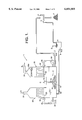
- FIG. 1 is an overall configuration view of an exhaust gas desulfurization system, which is one example of embodiment of the present invention
- FIG. 2 is a perspective view of the principal portion of the system shown in FIG. 1;
- FIG. 3 is a side sectional view showing the construction of spray pipe for the system shown in FIGS. 1 and 2;
- FIG. 4 is a partially sectional view showing the construction of spray pipe for the system shown in FIGS. 1 and 2;
- FIG. 5 is a sectional view taken along the line XI--XI of FIG. 3, showing the construction of spray pipe for the system shown in FIGS. 1 and 2;
- FIG. 6 is a view showing the result (blow-up state of each nozzle) of experiment using a spray pipe in accordance with the embodiment of the present invention
- FIG. 7 is a view showing the result (blow-up state of each nozzle) of experiment using a spray pipe which is a comparative example of the present invention.
- FIG. 8 is a view showing the result (blow-up state of each nozzle) of experiment using a spray pipe in accordance with the embodiment of the present invention.
- FIG. 9 is a view showing the result (blow-up state of each nozzle) of experiment using a spray pipe in accordance with the embodiment of the present invention.
- FIG. 10 is a side sectional view showing the construction of spray pipe which is a comparative example of the present invention.
- FIG. 11 is a schematic view for illustrating the outline of equipment used in Experiment 3.
- FIG. 12 is a schematic view for illustrating the transfer of heaps of scales in the spray pipe.
- FIG. 13 is a sectional view for illustrating an embodiment in which the tilting plate 52 consists of a concave tilting plate.
- An exhaust gas desulfurization system of this example has, as shown in FIG. 1, a gas-liquid contact apparatus 1 as shown in FIG. 2 as a gas-liquid contact apparatus for bringing absorbent slurry (liquid) into contact with exhaust gas (gas) and further with air for oxidation.
- This gas-liquid contact apparatus 1 includes a tank 10 for supplying absorbent slurry (calcium-containing slurry, in this case, limestone slurry), an inlet-side absorption tower (contact treatment tower) 20 which extends upward from one side portion (left side in the figure) of the tank 10 and at the top end of which an exhaust gas introducing portion 21 is formed to introduce untreated exhaust gas A, and an outlet-side absorption tower (contact treatment tower) 30 which extends upward from the other side portion (right side in the figure) of the tank 10, at the top end of which an exhaust gas discharging portion 31 is formed to discharge treated exhaust gas B, and in which the exhaust gas passing through the inlet-side absorbent 20 and the upper part of the tank 10 flows upward.
- absorbent slurry calcium-containing slurry, in this case, limestone slurry
- an inlet-side absorption tower (contact treatment tower) 20 which extends upward from one side portion (left side in the figure) of the tank 10 and at the top end of which an exhaust gas introducing portion 21 is formed to introduce
- Each of the absorption towers 20 and 30 is provided with spray pipes 22 and 32, respectively.
- Each of these spray pipes 22 and 32 is formed with a plurality of nozzles 23 and 33 which inject absorbent slurry upward in a liquid column form.
- a circulating pump 24, 34 for blowing up absorbent slurry in the tank 10 is provided so that the absorbent slurry is fed into the spray pipes 22, 32 via a supply pipe 25, 35 and injected through the nozzles 23, 33.
- a mist eliminator 30a is provided at the upper part of the outlet-side absorption tower 30 to trap and remove entrained mist. The mist trapped by this mist eliminator 30a returns into the tank 10 directly, for example, by dropping in the outlet-side absorption tower 30.
- the spray pipes 22, 32 are arranged in plural numbers in parallel to each other over the transverse range in the absorption tower as shown in FIG. 2, and the other end of each spray pipe is connected to each of a plurality of places in the lengthwise direction of the supply pipe 25, 35.
- the supply pipe 25, 35 is of a tapered shape toward the closed one end in the range in which the spray pipes 22, 23 are connected so that the cross-sectional area of flow passage decreases.
- the rate of decrease in flow passage cross-sectional area of the supply pipe 25, 35 is set so that the average flow velocity inside the pipe is substantially constant in the lengthwise direction.
- an air supplying means 11 is provided in the tank 10.
- the absorbent slurry which is blown up from the spray pipe 22, 23 and flows down while absorbing sulfur dioxide gas, is oxidized by the air blown from the air supplying means 11 in the tank 10, by which gypsum is obtained as a by-product.
- the air supplying means 11 being of an arm rotating type in this case, has a stirring rods 13 which are supported by a hollow rotating shaft 12 in the tank 10 and horizontally rotated by a not illustrated motor, an air supply pipes 14 which extend from the hollow rotating shaft 12 and whose open end extends to the lower side of the stirring rod 13, and a rotary joint 15 for connecting the base end of the hollow rotating shaft 12 to an air source.
- air C is supplied to a gas phase region produced on the back side of the stirring rod 13 in the rotating direction by the air supply pipes 14 by rotating the hollow rotating shaft 12 while air C is supplied under pressure from the rotary joint 15, by which a breaking phenomenon of the gas phase region edge portion is caused by the whirlpool force produced by the rotation of the stirring rod 13, so that many substantially uniform fine bubbles are generated.
- the absorbent slurry solution having absorbed sulfur dioxide gas is efficiently brought into contact with the air in the tank 10.
- the slurry (gypsum and a small amount of limestone, which is absorbent, are suspended or solved) in the tank 10 is sucked by a slurry pump 2 and supplied to a solid-liquid separator 3, being filtered and taken out as gypsum F containing less water (usually, water content of about 10%).
- the filtrate from the solid-liquid separator 3 is sent to a slurry tank 4, where limestone E is added together with make-up water, and again supplied into the tank 1 by a slurry pump 5.
- Reference numeral 16 in FIG. 2 denotes an air blower for supplying air to the air supplying means 11 via the rotary joint 15.
- the spray pipe 22, 32 is formed with a plurality of circular holes at constant intervals on the upper side of the pipe 41 having a circular cross section (constant cross section), and a cylindrical member 42 for installing nozzle is fixed around the top face of the circular hole by welding etc.
- a nozzle body 43 is fitted into the cylindrical member 42, and fastened by a flange 44 installed at the top end outer periphery of the cylindrical member 42, by which the nozzle 23, 33 is configured.
- a pipe with a pipe inside diameter of about 200 to 300 mm which is provided with nozzles at intervals of about 500 mm can be used.
- the energy loss caused by frictional resistance etc. can almost be neglected.
- about ten nozzles 23, 33 are arranged on one spray pipe.
- an end constituting member 50 composed of an end plate 51 and a tilting plate 52 is provided on the inside of one end (right-side end in the FIG. 3) of the pipe 41.
- the end constituting member 50 which has been manufactured integrally in advance by welding etc., is inserted from one end of the pipe 41, fixedly installed, for example, by welding the outer face outer periphery of the end plate 51 to the pipe 41.
- the end plate 51 for closing one end of the pipe 41 and the tilting plate 52 are provided.
- the tilting plate 52 forms the flow passage on the closed end side of the spray pipe 22, 32 into a shape such that the flow passage cross sectional area decreases toward the closed end.
- the tip end of the tilting plate 52 is disposed at the substantially middle position between the third and fourth nozzles from the closed end side of the spray pipe 22, 32.
- the tip end is in close contact with the inner bottom surface of the pipe 41, and tilts to the nozzle side (upper side) toward the base end side (closed end side) connected to the end plate by welding etc.
- This tilting plate 52 partitions the interior of the pipe 41 by being formed into a shape such that both ends join to the inner surface of the pipe 41.
- the length of the region in which the flow passage cross-sectional area decreases may be a length of the region where the blow-up heights are disturbed and lower than those of slurry from other nozzles, though it changes depending on the inside diameter of spray pipe, the intervals of nozzles, the injection pressure of slurry, etc.
- the tilting plate is preferably arranged from the middle position between the third and fourth nozzles or from the middle position between the fourth and fifth nozzles from the most downstream nozzle.
- the tilt angle of the tilting plate 52 is preferably such that the flow passage cross-sectional area at the centerline position of the first nozzle from the closed end of spray pipe 22, 32 is approximately 20% of the inside cross-sectional area of the pipe 41 itself. That is, the flow passage cross-sectional area on the tilting plate at the position of the most downstream nozzle is 0.2 to 0.3 times the cross-sectional area of spray pipe.
- a holding member 53 of a Y shape in cross section is provided integrally in advance by welding etc., by which the tip end of the tilting plate 52 is held in a state such as to be in contact with the bottom surface of the pipe 41.
- the tilting plate can be installed easily and stably in the interior of pipe into which a tool (welding torch etc.) is inserted with difficulty.
- the distance L is set so that the following equation (4) holds.
- the absorbent slurry in the tank 10 is supplied to the spray pipes 22, 32 through the supply pipe 25, 35 by means of the circulating pump 24, 34.
- the exhaust gas is first introduced into the inlet-side absorption tower 20 through the exhaust gas introducing portion 21, and flows down in the absorption tower 20.
- the absorbent slurry supplied to the spray pipes 22 is injected upward from the nozzles 23 of the spray pipes 22.
- the absorbent slurry blown up upward disperses and then goes down.
- the going-down slurry and the blown-up slurry collide with each other to produce fine particles. Fine particulate slurry is produced successively, so that particulate slurry exists in a state of being dispersed in the tower and then drops slowly.
- the exhaust gas flowing down in the absorption tower 20 flows horizontally at the upper part of the tank 10, and then enters the absorption tower 30 from the downside and rises in the absorption tower 30.
- absorbent slurry is injected upward from the nozzles 33 of the spray pipes 32.
- the slurry and the exhaust gas are mixed effectively, by which the almost all remaining sulfur dioxide gas is finally removed in this counter flow type absorption tower 30.
- air C sent from the air blower 16 is blown into the slurry as fine bubbles by using the air supplying means 11.
- the absorbent slurry which absorbs sulfur dioxide gas and flows down in the absorption towers 20 and 30, comes in contact with the air and is oxidized to yield gypsum.
- the blow-up of slurry from the nozzles 23, 33 of the spray pipe 22, 32 is uniform and stable over the whole range as shown in FIG. 6. Therefore, the gas-liquid contact between the exhaust gas and the absorbent slurry is effected uniformly over the entire horizontal region in the absorption tower, so that efficient absorption treatment is carried out. Thereby, a high desulfurization percentage is maintained while the circulation quantity (supply quantity) of slurry supplied by the circulating pumps 24 and 25 is held at the necessary minimum.
- tilting plate 52 Another important function of the tilting plate 52 is to transfer heaps of scales, which are mixed in the liquid supplied into the spray pipe from the oxidation tank via the pump, to the position under the most downstream nozzle along the tilting plate 52 by the liquid flow and to discharge them from the most downstream nozzle without accumulation in the spray pipe.
- the end plate 51 performs an important function to restrain the variation in height level of liquid column from the most downstream nozzle. That is, the end plate 51 prevents the development of whirlpool occurring at the closed end pocket portion of spray pipe.
- the end plate 51 prevents the development of whirlpool occurring at the end pocket portion and restrain the variation in height level of liquid column from the most downstream nozzle.
- it also has a function of raising and discharging the heaps of scales transferred to the position under the most downstream nozzle by using the slightly remaining whirlpool.
- the blow-up state of slurry (liquid) from the nozzles can be made uniform and stable over the entire region in the tower. Accordingly, efficient gas-liquid contact can be achieved without a wasteful increase in slurry circulation flow rate due to a bad blow-up state in some portions, which contributes greatly to the improvement in desulfurization percentage and the decrease in operation cost.
- the supply pipe 25, 35 and the spray pipes 22, 32 are configured so that the flow passage cross-sectional area decreases toward the downstream flow, the decrease in flow velocity toward the downstream flow is inhibited (especially, in the supply pipe, the flow velocity is substantially constant). Therefore, a phenomenon that the solid matters in slurry are settled and adhere to the bottom surface in the pipe, turning to scales, by the decrease in flow velocity can be prevented.
- gas-liquid contact (absorption of sulfur dioxide gas) can be performed at two stages because two absorption towers are provided for one tank. For this reason, even if the height of each contact treatment tower (absorption tower) and the circulating flow rate of slurry are equal to or less than those of the conventional apparatus, a gas-liquid contact efficiency (desulfurization percentage) equal to or higher than that of the conventional apparatus can be obtained. Moreover, since what we call the counter flow type gas-liquid contact, which has a higher contact efficiency than the parallel flow type, is performed in the outlet-side contact treatment tower (outlet-side absorption tower), the gas-liquid contact efficiency can further be increased as compared with the case where merely two parallel flow type gas-liquid contact apparatuses are connected in series.
- the spray pipe can be constructed so that the pipe body portion (for example, the aforementioned pipe 41) itself is of a tapered shape toward the closed end.
- the blow-up height must be increased to achieve a predetermined desulfurization percentage by using one absorption tower. Therefore, the operation of the present invention becomes more remarkable, so that a greater effect can be achieved.
- the desulfurization system of the present invention is not limited to the tank oxidation system as described in the above embodiment, and it may be configured so as to separately provide, for example, an oxidation tower.
- the gas-liquid contact apparatus of the present invention is not limited to a case where it is used as a facility for absorption process in the exhaust gas desulfurization system as described above, and can be used in a variety of fields, if the process requires efficient contact of liquid with gas.
- FIG. 9 shows the photography result in the case where the overall blow-up heights are about 7 m.
- FIG. 6 shows the photography result in the case where the overall blow-up heights are about 7 m.
- FIG. 8 shows the photography result in the case where the overall blow-up heights are about 7 m.
- blow-up state being good is thought to be as follows:
- the flow passage of spray pipe is of a tapered shape as shown in FIG. 3, and the end plate 51 is disposed on the inside from the maximum inlet internal diameter of nozzle, as indicated by the arrows in FIG. 3, the flow repelled by the end plate 51 and going in the counter direction is not produced, so that the liquid flows into the inlet of each nozzle stably in a well-regulated manner. Therefore, the disturbance of blow-up state and the variation in height do not occur, and the flow velocity is made uniform. Thereby, the static pressure affecting the blow-up height is also made uniform, so that the blow-up heights for other nozzles (nozzles distant from the closed end) are made uniform.
- FIG. 11 shows testing equipment.
- the liquid discharged from the liquid column nozzles is returned to a tank and reused by circulation.
- Tests were performed by the following procedure by assuming two cases of normal operation and restart after short-term operation stoppage.
- a whirlpool is produced on the downstream side of the heaps of scales on the spray pipe bottom and the tilting plate. If a plural number of heaps of scales 41b pile up into a mountain shape as shown in FIG. 12, the heaps of scales 41b on the upstream side get over the mountain successively and are positioned on the downstream side; thus, the dispersed heaps of scales move slidingly.
- the tilting plate 52 should preferably be in a concave form as shown in FIG. 13.
- the heaps of scales When the heaps of scales are discharged from the end nozzle, the heaps of scales reaching a position on the tilting plate 52 under the end nozzle are raised by a weak whirlpool of circulating liquid going toward the nozzle and discharged.
- the heaps of scales larger than about 20 mm are discharged in such a manner as to wait the generation of a suitable whirlpool, and even a plural number of them are discharged successively.
- the circulating liquid quantity should be 200 m 3 /m 2 h or more, preferably 240 m 3 /m 2 h or more.
- the blow-up state from the spray pipes is uniform and stable, so that a high desulfurization percentage can be obtained.
- the present invention achieves a reduction in operation cost. Therefore, the industrial applicability of the present invention is high.
Applications Claiming Priority (3)
| Application Number | Priority Date | Filing Date | Title |
|---|---|---|---|
| JP1666296 | 1996-02-01 | ||
| JP8-016662 | 1996-02-01 | ||
| PCT/JP1997/000152 WO1997027931A1 (fr) | 1996-02-01 | 1997-01-24 | Appareil de desulfuration de gaz d'echappement |
Publications (1)
| Publication Number | Publication Date |
|---|---|
| US6051055A true US6051055A (en) | 2000-04-18 |
Family
ID=11922551
Family Applications (1)
| Application Number | Title | Priority Date | Filing Date |
|---|---|---|---|
| US09/117,566 Expired - Lifetime US6051055A (en) | 1996-02-01 | 1997-01-24 | Exhaust gas desulfurization system |
Country Status (11)
| Country | Link |
|---|---|
| US (1) | US6051055A (xx) |
| EP (1) | EP0882487B1 (xx) |
| JP (1) | JP3207433B2 (xx) |
| KR (1) | KR100300488B1 (xx) |
| CN (1) | CN1108847C (xx) |
| DK (1) | DK0882487T3 (xx) |
| ES (1) | ES2193348T3 (xx) |
| PL (2) | PL186336B1 (xx) |
| TR (1) | TR199801461T2 (xx) |
| TW (1) | TW335357B (xx) |
| WO (1) | WO1997027931A1 (xx) |
Cited By (15)
| Publication number | Priority date | Publication date | Assignee | Title |
|---|---|---|---|---|
| US20060088452A1 (en) * | 2003-01-31 | 2006-04-27 | Hajime Okura | Exhaust gas processing device, and method of using the same |
| US20080199379A1 (en) * | 2005-09-02 | 2008-08-21 | Basf Se | Method and Device For Removing Sulphur Dioxide From a Dry Gas Stream |
| US20100089231A1 (en) * | 2005-02-14 | 2010-04-15 | Neumann Systems Group, Inc. | Apparatus and method thereof |
| US20100089232A1 (en) * | 2005-02-14 | 2010-04-15 | Neumann Systems Group, Inc | Liquid contactor and method thereof |
| US20100320294A1 (en) * | 2005-02-14 | 2010-12-23 | Neumann Systems Group, Inc. | Gas liquid contactor and effluent cleaning system and method |
| US20110126710A1 (en) * | 2005-02-14 | 2011-06-02 | Neumann Systems Group, Inc. | Two phase reactor |
| US7971860B1 (en) | 2010-05-25 | 2011-07-05 | Caldwell Tanks, Inc. | System and method for repairing or servicing a misting array assembly of an abatement system |
| CN102716659A (zh) * | 2012-06-29 | 2012-10-10 | 中电投远达环保工程有限公司 | 氧化沟串联布置的脱硫塔及使用此脱硫塔的脱硫系统 |
| EP2586517A1 (en) * | 2011-10-31 | 2013-05-01 | Mitsubishi Heavy Industries | Flue gas desulfurization |
| US20140140898A1 (en) * | 2010-02-25 | 2014-05-22 | Alstom Technology Ltd. | Wet scrubber and a method of cleaning a process gas |
| US8864876B2 (en) | 2005-02-14 | 2014-10-21 | Neumann Systems Group, Inc. | Indirect and direct method of sequestering contaminates |
| US8870166B2 (en) | 2010-05-25 | 2014-10-28 | Caldwell Tanks, Inc. | Misting array assembly of an abatement system |
| US20140331447A1 (en) * | 2013-05-10 | 2014-11-13 | Mei Thung Co., Ltd. | Nozzle of dust blower |
| JP2022046572A (ja) * | 2015-12-10 | 2022-03-23 | ヴェロ・スリー・ディー・インコーポレイテッド | 性能向上した3次元印刷 |
| US11691343B2 (en) | 2016-06-29 | 2023-07-04 | Velo3D, Inc. | Three-dimensional printing and three-dimensional printers |
Families Citing this family (14)
| Publication number | Priority date | Publication date | Assignee | Title |
|---|---|---|---|---|
| ATE281186T1 (de) * | 1997-04-23 | 2004-11-15 | Krones Ag | Vorrichtung zur flüssigkeitsbeaufschlagung von gefässen |
| JP2006122862A (ja) * | 2004-11-01 | 2006-05-18 | Mitsubishi Heavy Ind Ltd | 排ガス処理装置 |
| CN100393393C (zh) * | 2006-03-30 | 2008-06-11 | 国电科技环保集团有限公司 | 烟气脱硫吸收塔入口烟气喷淋预洗涤装置 |
| JP4418987B2 (ja) * | 2006-07-04 | 2010-02-24 | 健 木村 | 有害ガスの脱硫装置 |
| KR100906805B1 (ko) * | 2007-08-28 | 2009-07-09 | (주)하이텍산업개발 | 화력발전소용 배기가스 습식 탈황 장치 |
| CN102225308A (zh) * | 2011-04-25 | 2011-10-26 | 上海中芬新能源投资有限公司 | 一种湿法烟气脱硫吸收塔 |
| CN102343215B (zh) * | 2011-09-28 | 2013-07-24 | 华南理工大学 | 一种双室多重吸收湿法烟气脱硫装置 |
| AT512543B1 (de) * | 2012-07-17 | 2013-09-15 | Andritz Energy & Environment Gmbh | Anlage und Verfahren zur Absorption von Einzelkomponenten in Gasen |
| CN106035002A (zh) * | 2016-06-15 | 2016-10-26 | 镇江市都市生态农业有限公司 | 生态农业用供水装置 |
| CN108211622B (zh) * | 2018-01-19 | 2023-07-14 | 苏州银雀智能科技有限公司 | 一种快速除霾r型工程车 |
| JP7043276B2 (ja) * | 2018-02-05 | 2022-03-29 | 三菱重工業株式会社 | スプレイパイプ及び脱硫装置 |
| CN108159867A (zh) * | 2018-03-13 | 2018-06-15 | 湖北金鹏三益环保科技有限公司 | 一种文氏效应塔 |
| JP7193261B2 (ja) * | 2018-07-13 | 2022-12-20 | 三菱重工業株式会社 | 湿式排煙脱硫装置の制御方法、湿式排煙脱硫装置の制御装置、及びこの湿式排煙脱硫装置の制御装置を備えた遠隔監視システム |
| RU2715844C1 (ru) * | 2019-06-13 | 2020-03-03 | Федеральное государственное бюджетное образовательное учреждение высшего образования "Юго-Западный государственный университет" (ЮЗГУ) | Устройство для абсорбции отдельных компонентов в газах |
Citations (17)
| Publication number | Priority date | Publication date | Assignee | Title |
|---|---|---|---|---|
| US2014044A (en) * | 1934-05-18 | 1935-09-10 | Arthur B Haswell | Method of cleaning gas |
| US3225522A (en) * | 1962-09-10 | 1965-12-28 | Black Bernard | Gas and liquid contact device |
| US3928005A (en) * | 1974-02-19 | 1975-12-23 | Fuller Co | Method and apparatus for treating gaseous pollutants in a gas stream |
| JPS5499080A (en) * | 1978-01-23 | 1979-08-04 | Babcock Hitachi Kk | Spray type gas-liquid contact apparatus |
| US4263021A (en) * | 1972-12-05 | 1981-04-21 | The Babcock & Wilcox Company | Gas-liquid contact system |
| US4305909A (en) * | 1979-10-17 | 1981-12-15 | Peabody Process Systems, Inc. | Integrated flue gas processing system |
| JPS5953828A (ja) * | 1982-09-21 | 1984-03-28 | Konishiroku Photo Ind Co Ltd | 画像記録複写装置 |
| JPS6261617A (ja) * | 1985-09-13 | 1987-03-18 | Babcock Hitachi Kk | 排ガス洗浄装置 |
| EP0253605A2 (en) * | 1986-07-14 | 1988-01-20 | Albany International Corp. | Shower pipes |
| US5053061A (en) * | 1988-11-14 | 1991-10-01 | Mitsubishi Jukogyo Kabushiki Kaisha | Gas-liquid contacting method |
| EP0496295A1 (en) * | 1991-01-22 | 1992-07-29 | Mitsubishi Jukogyo Kabushiki Kaisha | High-Performance flue-gas desulfurization process and apparatus |
| US5173093A (en) * | 1991-07-26 | 1992-12-22 | The Babcock & Wilcox Company | Single spray level for flue gas desulfurization system |
| US5246471A (en) * | 1992-02-07 | 1993-09-21 | The Babcock & Wilcox Company | Method and apparatus for gas liquid contact |
| US5271873A (en) * | 1992-05-21 | 1993-12-21 | The Babcock & Wilcox Company | Support of interspaced, opposed feed headers for FGD systems |
| EP0676230A2 (en) * | 1994-04-11 | 1995-10-11 | Mitsubishi Jukogyo Kabushiki Kaisha | Gas-liquid contacting apparatus |
| US5512085A (en) * | 1992-06-25 | 1996-04-30 | Envirocare International, Inc. | Venturi scrubber and method with optimized remote spray |
| US5785901A (en) * | 1996-06-04 | 1998-07-28 | Mitsubishi Heavy Industries, Ltd. | Gas-liquid contact apparatus |
-
1997
- 1997-01-24 US US09/117,566 patent/US6051055A/en not_active Expired - Lifetime
- 1997-01-24 TR TR1998/01461T patent/TR199801461T2/xx unknown
- 1997-01-24 PL PL97350622A patent/PL186336B1/pl unknown
- 1997-01-24 PL PL97328071A patent/PL183927B1/pl unknown
- 1997-01-24 JP JP51108997A patent/JP3207433B2/ja not_active Expired - Lifetime
- 1997-01-24 ES ES97900767T patent/ES2193348T3/es not_active Expired - Lifetime
- 1997-01-24 DK DK97900767T patent/DK0882487T3/da active
- 1997-01-24 CN CN97191957A patent/CN1108847C/zh not_active Expired - Lifetime
- 1997-01-24 WO PCT/JP1997/000152 patent/WO1997027931A1/ja active IP Right Grant
- 1997-01-24 EP EP97900767A patent/EP0882487B1/en not_active Expired - Lifetime
- 1997-01-24 KR KR1019980705916A patent/KR100300488B1/ko not_active IP Right Cessation
- 1997-03-04 TW TW086102562A patent/TW335357B/zh not_active IP Right Cessation
Patent Citations (20)
| Publication number | Priority date | Publication date | Assignee | Title |
|---|---|---|---|---|
| US2014044A (en) * | 1934-05-18 | 1935-09-10 | Arthur B Haswell | Method of cleaning gas |
| US3225522A (en) * | 1962-09-10 | 1965-12-28 | Black Bernard | Gas and liquid contact device |
| US4263021A (en) * | 1972-12-05 | 1981-04-21 | The Babcock & Wilcox Company | Gas-liquid contact system |
| US3928005A (en) * | 1974-02-19 | 1975-12-23 | Fuller Co | Method and apparatus for treating gaseous pollutants in a gas stream |
| JPS5499080A (en) * | 1978-01-23 | 1979-08-04 | Babcock Hitachi Kk | Spray type gas-liquid contact apparatus |
| US4305909A (en) * | 1979-10-17 | 1981-12-15 | Peabody Process Systems, Inc. | Integrated flue gas processing system |
| JPS5953828A (ja) * | 1982-09-21 | 1984-03-28 | Konishiroku Photo Ind Co Ltd | 画像記録複写装置 |
| JPS6261617A (ja) * | 1985-09-13 | 1987-03-18 | Babcock Hitachi Kk | 排ガス洗浄装置 |
| EP0253605A2 (en) * | 1986-07-14 | 1988-01-20 | Albany International Corp. | Shower pipes |
| US5053061A (en) * | 1988-11-14 | 1991-10-01 | Mitsubishi Jukogyo Kabushiki Kaisha | Gas-liquid contacting method |
| EP0496295A1 (en) * | 1991-01-22 | 1992-07-29 | Mitsubishi Jukogyo Kabushiki Kaisha | High-Performance flue-gas desulfurization process and apparatus |
| US5173093A (en) * | 1991-07-26 | 1992-12-22 | The Babcock & Wilcox Company | Single spray level for flue gas desulfurization system |
| EP0524729A1 (en) * | 1991-07-26 | 1993-01-27 | The Babcock & Wilcox Company | Spray level apparatus and methods for flue gas desulphurisation |
| US5246471A (en) * | 1992-02-07 | 1993-09-21 | The Babcock & Wilcox Company | Method and apparatus for gas liquid contact |
| US5271873A (en) * | 1992-05-21 | 1993-12-21 | The Babcock & Wilcox Company | Support of interspaced, opposed feed headers for FGD systems |
| US5512085A (en) * | 1992-06-25 | 1996-04-30 | Envirocare International, Inc. | Venturi scrubber and method with optimized remote spray |
| EP0676230A2 (en) * | 1994-04-11 | 1995-10-11 | Mitsubishi Jukogyo Kabushiki Kaisha | Gas-liquid contacting apparatus |
| US5605655A (en) * | 1994-04-11 | 1997-02-25 | Mitsubishi Jukogyo Kabushiki Kaisha | Gas-liquid contacting apparatus |
| US5616290A (en) * | 1994-04-11 | 1997-04-01 | Mitsubishi Jukogyo Kabushiki Kaisha | Gas-liquid contacting apparatus |
| US5785901A (en) * | 1996-06-04 | 1998-07-28 | Mitsubishi Heavy Industries, Ltd. | Gas-liquid contact apparatus |
Cited By (39)
| Publication number | Priority date | Publication date | Assignee | Title |
|---|---|---|---|---|
| US7651329B2 (en) * | 2003-01-31 | 2010-01-26 | Babcock-Hitachi Kabushiki Kaisha | Exhaust gas processing device, and method of using the same |
| US20060088452A1 (en) * | 2003-01-31 | 2006-04-27 | Hajime Okura | Exhaust gas processing device, and method of using the same |
| US8216346B2 (en) * | 2005-02-14 | 2012-07-10 | Neumann Systems Group, Inc. | Method of processing gas phase molecules by gas-liquid contact |
| US8864876B2 (en) | 2005-02-14 | 2014-10-21 | Neumann Systems Group, Inc. | Indirect and direct method of sequestering contaminates |
| US20100089232A1 (en) * | 2005-02-14 | 2010-04-15 | Neumann Systems Group, Inc | Liquid contactor and method thereof |
| US8262777B2 (en) | 2005-02-14 | 2012-09-11 | Neumann Systems Group, Inc. | Method for enhancing a gas liquid contactor |
| US20100319539A1 (en) * | 2005-02-14 | 2010-12-23 | Neumann Systems Group, Inc. | Gas liquid contactor and effluent cleaning system and method |
| US20110061530A1 (en) * | 2005-02-14 | 2011-03-17 | Neumann Systems Group, Inc. | Apparatus and method thereof |
| US20110061531A1 (en) * | 2005-02-14 | 2011-03-17 | Neumann Systems Group, Inc. | Apparatus and method thereof |
| US20110072968A1 (en) * | 2005-02-14 | 2011-03-31 | Neumann Systems Group, Inc. | Apparatus and method thereof |
| US20110081288A1 (en) * | 2005-02-14 | 2011-04-07 | Neumann Systems Group, Inc. | Apparatus and method thereof |
| US20110126710A1 (en) * | 2005-02-14 | 2011-06-02 | Neumann Systems Group, Inc. | Two phase reactor |
| US20100089231A1 (en) * | 2005-02-14 | 2010-04-15 | Neumann Systems Group, Inc. | Apparatus and method thereof |
| US8668766B2 (en) | 2005-02-14 | 2014-03-11 | Neumann Systems Group, Inc. | Gas liquid contactor and method thereof |
| US8398059B2 (en) | 2005-02-14 | 2013-03-19 | Neumann Systems Group, Inc. | Gas liquid contactor and method thereof |
| US8088292B2 (en) | 2005-02-14 | 2012-01-03 | Neumann Systems Group, Inc. | Method of separating at least two fluids with an apparatus |
| US8105419B2 (en) | 2005-02-14 | 2012-01-31 | Neumann Systems Group, Inc. | Gas liquid contactor and effluent cleaning system and method |
| US8113491B2 (en) * | 2005-02-14 | 2012-02-14 | Neumann Systems Group, Inc. | Gas-liquid contactor apparatus and nozzle plate |
| US8323381B2 (en) * | 2005-02-14 | 2012-12-04 | Neumann Systems Group, Inc. | Two phase reactor |
| US8216347B2 (en) | 2005-02-14 | 2012-07-10 | Neumann Systems Group, Inc. | Method of processing molecules with a gas-liquid contactor |
| US20100320294A1 (en) * | 2005-02-14 | 2010-12-23 | Neumann Systems Group, Inc. | Gas liquid contactor and effluent cleaning system and method |
| US8814146B2 (en) | 2005-02-14 | 2014-08-26 | Neumann Systems Group, Inc. | Two phase reactor |
| US8336863B2 (en) | 2005-02-14 | 2012-12-25 | Neumann Systems Group, Inc. | Gas liquid contactor and effluent cleaning system and method |
| US20080199379A1 (en) * | 2005-09-02 | 2008-08-21 | Basf Se | Method and Device For Removing Sulphur Dioxide From a Dry Gas Stream |
| US8840714B2 (en) * | 2010-02-25 | 2014-09-23 | Alstom Technology Ltd | Wet scrubber and a method of cleaning a process gas |
| US20140140898A1 (en) * | 2010-02-25 | 2014-05-22 | Alstom Technology Ltd. | Wet scrubber and a method of cleaning a process gas |
| US7971860B1 (en) | 2010-05-25 | 2011-07-05 | Caldwell Tanks, Inc. | System and method for repairing or servicing a misting array assembly of an abatement system |
| US8439333B2 (en) | 2010-05-25 | 2013-05-14 | Caldwell Tanks, Inc. | Removable misting array assembly for an abatement system |
| US7975990B1 (en) | 2010-05-25 | 2011-07-12 | Caldwell Tanks, Inc. | Misting array assembly having adjustable nozzles |
| US7971859B1 (en) | 2010-05-25 | 2011-07-05 | Caldwell Tanks, Inc. | Misting array assembly having upwardly and downwardly disposed nozzles |
| US8870166B2 (en) | 2010-05-25 | 2014-10-28 | Caldwell Tanks, Inc. | Misting array assembly of an abatement system |
| US9518735B2 (en) | 2010-05-25 | 2016-12-13 | Caldwell Tanks, Inc. | Nozzle assembly |
| EP2586517A1 (en) * | 2011-10-31 | 2013-05-01 | Mitsubishi Heavy Industries | Flue gas desulfurization |
| US9115895B2 (en) | 2011-10-31 | 2015-08-25 | Mitsubishi Hitachi Power Systems, Ltd. | Flue gas desulfurization |
| CN102716659A (zh) * | 2012-06-29 | 2012-10-10 | 中电投远达环保工程有限公司 | 氧化沟串联布置的脱硫塔及使用此脱硫塔的脱硫系统 |
| US20140331447A1 (en) * | 2013-05-10 | 2014-11-13 | Mei Thung Co., Ltd. | Nozzle of dust blower |
| US9233403B2 (en) * | 2013-05-10 | 2016-01-12 | Mei Thung Co., Ltd. | Nozzle of dust blower |
| JP2022046572A (ja) * | 2015-12-10 | 2022-03-23 | ヴェロ・スリー・ディー・インコーポレイテッド | 性能向上した3次元印刷 |
| US11691343B2 (en) | 2016-06-29 | 2023-07-04 | Velo3D, Inc. | Three-dimensional printing and three-dimensional printers |
Also Published As
| Publication number | Publication date |
|---|---|
| TR199801461T2 (xx) | 1998-10-21 |
| JP3207433B2 (ja) | 2001-09-10 |
| PL328071A1 (en) | 1999-01-04 |
| DK0882487T3 (da) | 2003-08-04 |
| PL183927B1 (pl) | 2002-08-30 |
| KR19990082191A (ko) | 1999-11-25 |
| ES2193348T3 (es) | 2003-11-01 |
| EP0882487B1 (en) | 2003-04-09 |
| EP0882487A4 (en) | 1999-12-08 |
| EP0882487A1 (en) | 1998-12-09 |
| PL186336B1 (pl) | 2003-12-31 |
| TW335357B (en) | 1998-07-01 |
| WO1997027931A1 (fr) | 1997-08-07 |
| CN1108847C (zh) | 2003-05-21 |
| KR100300488B1 (ko) | 2002-02-28 |
| CN1209757A (zh) | 1999-03-03 |
Similar Documents
| Publication | Publication Date | Title |
|---|---|---|
| US6051055A (en) | Exhaust gas desulfurization system | |
| AU673915B2 (en) | Wet type flue gas desulfurizer | |
| EP0827765A2 (en) | Gas-liquid dispersion devices, gas-liquid contact apparatus and wastewater treatment systems | |
| CN100371054C (zh) | 具有阶梯托盘的烟道气脱硫系统 | |
| US6896851B1 (en) | Wet type flue gas desulfurization equipment | |
| KR20000069994A (ko) | 습식 가스 처리 방법 및 이를 이용한 장치 | |
| EP0712655A1 (en) | Gas-liquid contact gas dispersion pipe, and gas-liquid contact method and apparatus using the same | |
| JP3734291B2 (ja) | 排ガスの脱硫方法 | |
| US3405920A (en) | Process and device for stirring and methodically circulating liquid masses by blowing gases therethrough | |
| KR100285102B1 (ko) | 습식 연도 가스 탈황장치 및 연도 가스 탈황장치의 산소 함유가스 송풍장치 | |
| KR20040030789A (ko) | 기체로부터 이산화황을 분리하는 방법 및 장치 | |
| CZ319392A3 (en) | Concurrent dry scrubber | |
| JPH09865A (ja) | 排ガスの処理方法及び装置 | |
| WO1998033576A1 (en) | Open contact reactor | |
| GB2031747A (en) | Gas-liquid dissolving tank | |
| CN109432974B (zh) | 一种鼓泡式自动循环湿法烟气脱硫装置 | |
| KR20050007488A (ko) | 가스층 다공판형 배연 탈황 장치 | |
| Prasad et al. | Liquid circulation velocity and overall gas holdup in a modified jet loop bioreactor with low density particles | |
| BR112012028305B1 (pt) | Processo contínuo para contatar um reagente líquido sequencialmente com um gás de processo e um segundo gás, e, aparelho para um processo contínuo para contatar um reagente líquido sequencialmente com um gás de processo e um segundo gás | |
| JP3637140B2 (ja) | 排ガスの脱硫方法及び装置 | |
| JPH11137957A (ja) | 排煙脱硫装置 | |
| RU2258559C2 (ru) | Способ проведения газожидкостных многофазных реакций и вихревой центробежный барботажный реактор для его осуществления | |
| JPH09150032A (ja) | 排ガス処理移動層及びその操業方法 | |
| JPH07308536A (ja) | 多管式気液接触装置 | |
| JP3675957B2 (ja) | 排煙処理装置 |
Legal Events
| Date | Code | Title | Description |
|---|---|---|---|
| AS | Assignment |
Owner name: MITSUBISHI HEAVY INDUSTRIES, LTD., JAPAN Free format text: ASSIGNMENT OF ASSIGNORS INTEREST;ASSIGNORS:UKAWA, NAOHIKO;TAKASHINA, TORU;OKINO, SUSUMU;AND OTHERS;REEL/FRAME:009569/0529 Effective date: 19980703 |
|
| FEPP | Fee payment procedure |
Free format text: PAYOR NUMBER ASSIGNED (ORIGINAL EVENT CODE: ASPN); ENTITY STATUS OF PATENT OWNER: LARGE ENTITY |
|
| STCF | Information on status: patent grant |
Free format text: PATENTED CASE |
|
| FPAY | Fee payment |
Year of fee payment: 4 |
|
| FPAY | Fee payment |
Year of fee payment: 8 |
|
| FPAY | Fee payment |
Year of fee payment: 12 |
|
| AS | Assignment |
Owner name: MITSUBISHI HITACHI POWER SYSTEMS, LTD., JAPAN Free format text: ASSIGNMENT OF ASSIGNORS INTEREST;ASSIGNOR:MITSUBISHI HEAVY INDUSTRIES, LTD.;REEL/FRAME:035101/0029 Effective date: 20140201 |