US5862590A - Method of manufacturing catalytic converter for the purification of exhaust gas - Google Patents
Method of manufacturing catalytic converter for the purification of exhaust gas Download PDFInfo
- Publication number
- US5862590A US5862590A US08/835,737 US83573797A US5862590A US 5862590 A US5862590 A US 5862590A US 83573797 A US83573797 A US 83573797A US 5862590 A US5862590 A US 5862590A
- Authority
- US
- United States
- Prior art keywords
- catalyst carrier
- metal shell
- sheet
- mat
- alumina fiber
- Prior art date
- Legal status (The legal status is an assumption and is not a legal conclusion. Google has not performed a legal analysis and makes no representation as to the accuracy of the status listed.)
- Expired - Lifetime
Links
- 230000003197 catalytic effect Effects 0.000 title claims abstract description 21
- 238000000746 purification Methods 0.000 title claims abstract description 16
- 238000004519 manufacturing process Methods 0.000 title claims description 13
- 239000003054 catalyst Substances 0.000 claims abstract description 67
- 229910052751 metal Inorganic materials 0.000 claims abstract description 65
- 239000002184 metal Substances 0.000 claims abstract description 65
- 239000000835 fiber Substances 0.000 claims abstract description 49
- PNEYBMLMFCGWSK-UHFFFAOYSA-N aluminium oxide Inorganic materials [O-2].[O-2].[O-2].[Al+3].[Al+3] PNEYBMLMFCGWSK-UHFFFAOYSA-N 0.000 claims abstract description 46
- 238000003825 pressing Methods 0.000 claims abstract description 21
- 238000000034 method Methods 0.000 claims description 13
- 238000004804 winding Methods 0.000 claims description 11
- 101100495270 Caenorhabditis elegans cdc-26 gene Proteins 0.000 description 19
- 239000012784 inorganic fiber Substances 0.000 description 11
- 239000002390 adhesive tape Substances 0.000 description 7
- 229920005989 resin Polymers 0.000 description 5
- 239000011347 resin Substances 0.000 description 5
- 239000004698 Polyethylene Substances 0.000 description 4
- 230000000052 comparative effect Effects 0.000 description 4
- 229910052878 cordierite Inorganic materials 0.000 description 4
- JSKIRARMQDRGJZ-UHFFFAOYSA-N dimagnesium dioxido-bis[(1-oxido-3-oxo-2,4,6,8,9-pentaoxa-1,3-disila-5,7-dialuminabicyclo[3.3.1]nonan-7-yl)oxy]silane Chemical compound [Mg++].[Mg++].[O-][Si]([O-])(O[Al]1O[Al]2O[Si](=O)O[Si]([O-])(O1)O2)O[Al]1O[Al]2O[Si](=O)O[Si]([O-])(O1)O2 JSKIRARMQDRGJZ-UHFFFAOYSA-N 0.000 description 4
- BASFCYQUMIYNBI-UHFFFAOYSA-N platinum Chemical compound [Pt] BASFCYQUMIYNBI-UHFFFAOYSA-N 0.000 description 4
- -1 polyethylene Polymers 0.000 description 4
- 229920000573 polyethylene Polymers 0.000 description 4
- 239000010455 vermiculite Substances 0.000 description 4
- 229910052902 vermiculite Inorganic materials 0.000 description 4
- 235000019354 vermiculite Nutrition 0.000 description 4
- 239000000919 ceramic Substances 0.000 description 3
- 238000002485 combustion reaction Methods 0.000 description 3
- 238000007796 conventional method Methods 0.000 description 3
- 238000003780 insertion Methods 0.000 description 3
- 230000037431 insertion Effects 0.000 description 3
- 239000000203 mixture Substances 0.000 description 3
- 238000007789 sealing Methods 0.000 description 3
- 229910001220 stainless steel Inorganic materials 0.000 description 3
- 239000010935 stainless steel Substances 0.000 description 3
- 238000000354 decomposition reaction Methods 0.000 description 2
- 230000002349 favourable effect Effects 0.000 description 2
- 229920000554 ionomer Polymers 0.000 description 2
- 239000004816 latex Substances 0.000 description 2
- 229920000126 latex Polymers 0.000 description 2
- 239000000314 lubricant Substances 0.000 description 2
- 230000014759 maintenance of location Effects 0.000 description 2
- 239000002985 plastic film Substances 0.000 description 2
- 229920006255 plastic film Polymers 0.000 description 2
- 229910052697 platinum Inorganic materials 0.000 description 2
- 229920000915 polyvinyl chloride Polymers 0.000 description 2
- 239000004800 polyvinyl chloride Substances 0.000 description 2
- 238000009987 spinning Methods 0.000 description 2
- 230000002522 swelling effect Effects 0.000 description 2
- KXGFMDJXCMQABM-UHFFFAOYSA-N 2-methoxy-6-methylphenol Chemical compound [CH]OC1=CC=CC([CH])=C1O KXGFMDJXCMQABM-UHFFFAOYSA-N 0.000 description 1
- VYZAMTAEIAYCRO-UHFFFAOYSA-N Chromium Chemical compound [Cr] VYZAMTAEIAYCRO-UHFFFAOYSA-N 0.000 description 1
- 229920000742 Cotton Polymers 0.000 description 1
- 239000004677 Nylon Substances 0.000 description 1
- 230000015556 catabolic process Effects 0.000 description 1
- 229910052804 chromium Inorganic materials 0.000 description 1
- 239000011651 chromium Substances 0.000 description 1
- 230000006835 compression Effects 0.000 description 1
- 238000007906 compression Methods 0.000 description 1
- 238000006731 degradation reaction Methods 0.000 description 1
- 238000007598 dipping method Methods 0.000 description 1
- 239000004744 fabric Substances 0.000 description 1
- 238000005470 impregnation Methods 0.000 description 1
- 239000002655 kraft paper Substances 0.000 description 1
- 239000000463 material Substances 0.000 description 1
- 229920001778 nylon Polymers 0.000 description 1
- 239000000123 paper Substances 0.000 description 1
- 239000011087 paperboard Substances 0.000 description 1
- 229920001568 phenolic resin Polymers 0.000 description 1
- 239000005011 phenolic resin Substances 0.000 description 1
- 229920000728 polyester Polymers 0.000 description 1
- 230000010349 pulsation Effects 0.000 description 1
- 230000000452 restraining effect Effects 0.000 description 1
- 238000010008 shearing Methods 0.000 description 1
- 229920002050 silicone resin Polymers 0.000 description 1
- 238000005507 spraying Methods 0.000 description 1
- 230000008961 swelling Effects 0.000 description 1
- 229920003051 synthetic elastomer Polymers 0.000 description 1
- 229920003002 synthetic resin Polymers 0.000 description 1
- 239000000057 synthetic resin Substances 0.000 description 1
- 239000005061 synthetic rubber Substances 0.000 description 1
Images


Classifications
-
- B—PERFORMING OPERATIONS; TRANSPORTING
- B01—PHYSICAL OR CHEMICAL PROCESSES OR APPARATUS IN GENERAL
- B01J—CHEMICAL OR PHYSICAL PROCESSES, e.g. CATALYSIS OR COLLOID CHEMISTRY; THEIR RELEVANT APPARATUS
- B01J35/00—Catalysts, in general, characterised by their form or physical properties
- B01J35/50—Catalysts, in general, characterised by their form or physical properties characterised by their shape or configuration
- B01J35/56—Foraminous structures having flow-through passages or channels, e.g. grids or three-dimensional monoliths
-
- F—MECHANICAL ENGINEERING; LIGHTING; HEATING; WEAPONS; BLASTING
- F01—MACHINES OR ENGINES IN GENERAL; ENGINE PLANTS IN GENERAL; STEAM ENGINES
- F01N—GAS-FLOW SILENCERS OR EXHAUST APPARATUS FOR MACHINES OR ENGINES IN GENERAL; GAS-FLOW SILENCERS OR EXHAUST APPARATUS FOR INTERNAL COMBUSTION ENGINES
- F01N3/00—Exhaust or silencing apparatus having means for purifying, rendering innocuous, or otherwise treating exhaust
- F01N3/08—Exhaust or silencing apparatus having means for purifying, rendering innocuous, or otherwise treating exhaust for rendering innocuous
- F01N3/10—Exhaust or silencing apparatus having means for purifying, rendering innocuous, or otherwise treating exhaust for rendering innocuous by thermal or catalytic conversion of noxious components of exhaust
- F01N3/24—Exhaust or silencing apparatus having means for purifying, rendering innocuous, or otherwise treating exhaust for rendering innocuous by thermal or catalytic conversion of noxious components of exhaust characterised by constructional aspects of converting apparatus
- F01N3/28—Construction of catalytic reactors
- F01N3/2839—Arrangements for mounting catalyst support in housing, e.g. with means for compensating thermal expansion or vibration
- F01N3/2853—Arrangements for mounting catalyst support in housing, e.g. with means for compensating thermal expansion or vibration using mats or gaskets between catalyst body and housing
-
- F—MECHANICAL ENGINEERING; LIGHTING; HEATING; WEAPONS; BLASTING
- F16—ENGINEERING ELEMENTS AND UNITS; GENERAL MEASURES FOR PRODUCING AND MAINTAINING EFFECTIVE FUNCTIONING OF MACHINES OR INSTALLATIONS; THERMAL INSULATION IN GENERAL
- F16L—PIPES; JOINTS OR FITTINGS FOR PIPES; SUPPORTS FOR PIPES, CABLES OR PROTECTIVE TUBING; MEANS FOR THERMAL INSULATION IN GENERAL
- F16L59/00—Thermal insulation in general
- F16L59/04—Arrangements using dry fillers, e.g. using slag wool which is added to the object to be insulated by pouring, spreading, spraying or the like
-
- Y—GENERAL TAGGING OF NEW TECHNOLOGICAL DEVELOPMENTS; GENERAL TAGGING OF CROSS-SECTIONAL TECHNOLOGIES SPANNING OVER SEVERAL SECTIONS OF THE IPC; TECHNICAL SUBJECTS COVERED BY FORMER USPC CROSS-REFERENCE ART COLLECTIONS [XRACs] AND DIGESTS
- Y10—TECHNICAL SUBJECTS COVERED BY FORMER USPC
- Y10T—TECHNICAL SUBJECTS COVERED BY FORMER US CLASSIFICATION
- Y10T29/00—Metal working
- Y10T29/49—Method of mechanical manufacture
- Y10T29/49345—Catalytic device making
-
- Y—GENERAL TAGGING OF NEW TECHNOLOGICAL DEVELOPMENTS; GENERAL TAGGING OF CROSS-SECTIONAL TECHNOLOGIES SPANNING OVER SEVERAL SECTIONS OF THE IPC; TECHNICAL SUBJECTS COVERED BY FORMER USPC CROSS-REFERENCE ART COLLECTIONS [XRACs] AND DIGESTS
- Y10—TECHNICAL SUBJECTS COVERED BY FORMER USPC
- Y10T—TECHNICAL SUBJECTS COVERED BY FORMER US CLASSIFICATION
- Y10T29/00—Metal working
- Y10T29/49—Method of mechanical manufacture
- Y10T29/49826—Assembling or joining
- Y10T29/49863—Assembling or joining with prestressing of part
Definitions
- This invention relates to a method of manufacturing a catalytic converter for the purification of exhaust gas arranged in an exhaust system of an internal combustion engine, and more particularly to a method of manufacturing a catalytic converter arranged on the way of an exhaust pipe or an exhaust manifold in an exhaust system of a vehicle such as automobiles or the like to conduct the purification of exhaust gas.
- the catalytic converter for the purification of exhaust gas used in the exhaust system of the internal combustion engine comprises a catalyst carrier provided with a catalyst such as platinum or the like, a heat-insulating seal layer covering the outer surface of the catalyst carrier, and a metal shell housing an assembly of the carrier and the seal layer therein.
- the catalyst carrier in such a catalytic converter there is used a monolithic carrier having a honeycomb shape at section and made from cordierite or the like.
- an inorganic fiber sheet As the heat-insulating seal layer, there is mainly used an inorganic fiber sheet. This sheet is used for holding the catalyst carrier at an adequate temperature to effectively develop the catalytic action and for preventing the damage of the catalyst carrier due to the contact with the outer metal shell during the running of the vehicle or the like, or preventing the leakage of exhaust gas from a space between the metal shell and the catalyst carrier.
- JP-A-7-189677 and JP-A-7-189678 propose a method of facilitating the assembling of the catalyst carrier to the metal shell wherein the catalyst carrier covered with the inorganic fiber sheet as the heat-insulating seal layer is placed in a bag of an airtight film and then the inside of the bag is evacuated to reduce the thickness of the inorganic fiber sheet, or JP-A-57-146954 and JP-A-59-126023 propose a method wherein the inorganic fiber sheet is closely sealed in an airtight film bag and then wound around the catalyst carrier.
- the inorganic fiber sheet there has mainly been used an inorganic fiber sheet having an excellent handling property, which is comprised of a mixture of ceramic fibers and vermiculite being relatively poor in the heat resistance and having a high-temperature swelling property.
- the temperature of exhaust gas rises with the remarkable improvement of engine performances for automobiles and hence the inorganic fiber sheet used as the heat-insulating seal layer is required to have a higher heat resistance.
- the crystalline alumina fiber sheet is excellent in the heat resistance as compared with the inorganic fiber sheet made of the vermiculite and ceramic fiber mixture, but has drawbacks that it has not a high-temperature swelling property as in vermiculite and is relatively low in the fiber strength and the crystalline alumina fiber sheet is apt to broken under an influence of pulsation of the exhaust gas. Therefore, it is required to improve the sealing property by winding the crystalline alumina fiber sheet around the catalyst carrier at a state of increasing the bulk density of the sheet.
- an object of the invention to solve the above problems of the conventional technique and to provide a method of manufacturing a catalytic converter for the purification of exhaust gas by inserting the catalyst carrier into the cylindrical metal shell through the crystalline alumina fiber sheet as a heat-insulating seal layer.
- a method of manufacturing a catalytic converter for the purification of exhaust gas comprising a catalyst carrier provided with a catalyst, a heat-insulating seal layer covering the outer surface of the catalyst carrier and a cylindrical metal shell housing the catalyst carrier and the heat-insulating seal layer therein, which comprises using a crystalline alumina fiber mat as a heat-insulating seal layer; providing an assembly comprising the catalyst carrier, the crystalline alumina fiber mat wound around the outer surface of the catalyst carrier and a sheet-shaped article covering the outer surface of the mat wherein at least a top portion of the sheet-shaped article to be inserted into the metal shell is fastened to the catalyst carrier; and pressing the assembly into the inside of the metal shell through a funnel-shaped fixture set on an entrance side of the metal shell to render a bulk density of the crystalline alumina fiber mat in use into 0.25-0.60 g/cm 3 .
- a size of the mat is made smaller than an inner diameter of the metal shell by winding the sheet-shaped article, and the funnel-shaped fixture has a slit and an overlapping portion so as to change a circumferential length thereof.
- the catalytic converter for the purification of exhaust gas is an assembly comprising a catalyst carrier provided with a catalyst, a heat-insulating seal layer covering the outer surface of the catalyst carrier and a cylindrical metal shell housing the carrier and the seal layer therein.
- the catalyst carrier there is a monolithic carrier provided with a catalyst such as conventionally used platinum or the like, having a honeycomb shape at section, and made from cordierite, alumina, chromium stainless steel or the like.
- the metal shell there is used a metal cylinder having a sectional shape usually used such as a circle, an ellipse or the like and made from a heat-resistant stainless steel such as SUS409 or the like.
- a crystalline alumina fiber mat absorbing a tolerance of an outer diameter of the catalyst carrier and having a given bulk density so as not to leak the exhaust gas in use after the assembling and an excellent heat resistance.
- This mat never causes the gas leakage due to the lowering of the swelling pressure as in the conventionally used seal layer and the degradation of the quality even when being particularly exposed to higher-temperature exhaust gas.
- a resin may previously be added to the mat from a viewpoint of the operability because the alumina fiber is relatively low in the handling strength and is broken when an excessively physical force is applied thereto.
- the resin use may be made of synthetic rubbers giving a flexibility such as NBR latex, SBR latex and the like; and phenolic resin and the like giving a shape retention after the impregnation.
- synthetic rubbers giving a flexibility
- SBR latex SBR latex
- phenolic resin and the like giving a shape retention after the impregnation.
- Such a resin is added by spraying method, dipping method or the like.
- the outer surface of the catalyst carrier is firstly covered with the crystalline alumina fiber mat as a heat-insulating seal layer, and then the sheet-shaped article is wound around the outer surface of the mat to be inserted into the metal shell under tension to fasten at least a top portion thereof to the top portion of the mat, and thereafter the assembly comprised of the catalyst carrier, crystalline alumina fiber mat and sheet-shaped article is pressed into the cylindrical metal shell through the funnel-shaped fixture set on the entrance side of the shell.
- plastic films made from polyethylene, silicone resin, polyvinyl chloride, ionomer resin and the like; woven or unwoven fabrics of cotton, nylon, polyester and the like; papers such as kraft paper, paperboard and the like.
- plastic films made from polyethylene, silicone resin, polyvinyl chloride, ionomer resin and the like; woven or unwoven fabrics of cotton, nylon, polyester and the like; papers such as kraft paper, paperboard and the like.
- the use of polyethylene or ionomer resin is preferable.
- the lubricity can be enhanced by applying a lubricant or the like to the outer surface of the sheet-shaped article or the inner surface of the metal shell.
- the sheet-shaped article After the sheet-shaped article is wound around the outer surface of the crystalline alumina fiber mat under given tension, at least a top portion of the article is fixed to the top portion of the mat by adequate means.
- a heat-shrinkable synthetic resin ring is fitted to the top portion of the sheet-shaped article, or a band-shaped ribbon or an adhesive tape is further wound around the top portion of the sheet-shaped article.
- the sheet-shaped article When the catalytic converter using such a sheet-shaped article is manufactured and incorporated into an exhaust system of an internal combustion engine to conduct a trial run, the sheet-shaped article is burnt by heat decomposition at a temperature of exhaust gas.
- the crystalline alumina fiber mat pressed into the metal shell has a bulk density of 0.25-0.60 g/cm 3 , preferably 0.3-0.5 g/cm 3 in use.
- the bulk density of the crystalline alumina fiber mat before the winding of the sheet-shaped article is 0.06-0.10 g/cm 3 , so that the bulk density in use after the pressing into the metal shell can easily be obtained within the above defined range by restraining the crystalline alumina fiber mat in a thickness-reducing direction through the winding of the sheet-shaped article under a given tension.
- the assembly comprised of the catalyst carrier, crystalline alumina fiber mat and sheet-shaped article is pressed into the metal shell by means of a pressing machine.
- the funnel-shaped fixture is previously set on an entrance side of the metal shell for facilitating the pressing of the assembly.
- This fixture has a slit and overlapping portions so as to change a circumferential length for absorbing a tolerance between the outer diameter of the assembly and the inner diameter of the metal shell. That is, since there are somewhat scatterings in the outer diameter of the assembly and the inner diameter of the metal shell, it is required that a tolerance of such scatterings can be absorbed by the funnel-shaped fixture.
- burr and the like are usually existent on the end portion of the metal shell, so that if the assembly is directly pressed into the metal shell, the sheet-shaped article as an outermost layer of the assembly is broken by the burr and the like and hence the crystalline alumina fiber mat is exposed and swollen and destroyed before the pressing.
- the top portion of the funnel-shaped fixture is previously and locally inserted into the metal shell.
- the insertion of the remaining portion of the assembly becomes more easy because it is possible to reduce the total size of the catalyst carrier and crystalline alumina fiber mat constituting the assembly, particularly the size of the mat as the heat-insulating seal layer at the pressing step.
- the assembly may be placed in a bag of an airtight plastic film and then be presses into the metal shell in a pressurizing chamber of 2-10 kg/cm 2 , preferably 4-7 kg/cm 2 by means of a pressing machine.
- both ends of the metal shell are drawn by pressing, or a cone-shaped metallic pipe is welded to each end of the metal shell to manufacture a catalytic converter for the purification of exhaust gas.
- the slippage between the catalyst carrier and crystalline alumina fiber mat inside the metal shell is not caused in the pressing, so that there is caused no movement nor breakage of the catalyst carrier in the metal shell even in the handling and transportation of the resulting converter. Therefore, the method according to the invention can be applied to any structures of the converter without being affected by a clearance between the catalyst carrier and the metal shell. Furthermore, shearing force is not applied to the mat, so that the excellent shape retention of catalyst carrier and sealing property to exhaust gas can be maintained over a long period of time.
- the catalytic converter for the purification of exhaust gas according to the invention is connected to an exhaust system of a vehicle in a factory for the manufacture of automobiles. Therefore, the sheet-shaped article covering the crystalline alumina fiber mat is burnt out by a higher temperature exhaust gas in trial run of the vehicle. Alternatively, the sheet-shaped article may previously be burnt out before the converter is connected to the exhaust system.
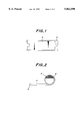
- FIG. 1 is a plan view illustrating a state of placing a crystalline alumina fiber mat on a sheet-shaped article
- FIG. 2 is a side view illustrating a state of winding an assembly shown in FIG. 1 around a catalyst carrier;
- FIG. 3 is a front view illustrating a state of winding the crystalline alumina fiber mat and the sheet-shaped article around the catalyst carrier and further winding an adhesive tape around a top portion thereof for fixation;
- FIG. 4 is a front view illustrating a state of setting a funnel-shaped fixture on a metal shell
- FIG. 5 is a perspective view of a funnel-shaped fixture
- FIG. 6 is a front view illustrating a state of pressing an assembly comprised of the catalyst carrier, crystalline alumina fiber mat and sheet-shaped article into the metal shell;
- FIG. 7 is a front view of a catalytic converter for the purification of exhaust gas worked at both end portions of the metal shell.
- FIGS. 8 and 9 are schematic views showing production steps of another assembly, respectively.
- a mat 4 of crystalline alumina fiber (trade name: Denkaarsen, made by Denki Kagaku Kogyo K.K.)having a thickness of 20 mm and a bulk density of 0.06 g/cm 3 is cut into dimensions of 100 mm in width, 420 mm in length and 25 mm in fitting portions formed on both ends, which is then placed on a polyethylene sheet 6 having a width of 200 mm, a length of 500 mm and a thickness of 50 ⁇ m.
- crystalline alumina fiber (trade name: Denkaarsen, made by Denki Kagaku Kogyo K.K.)having a thickness of 20 mm and a bulk density of 0.06 g/cm 3 is cut into dimensions of 100 mm in width, 420 mm in length and 25 mm in fitting portions formed on both ends, which is then placed on a polyethylene sheet 6 having a width of 200 mm, a length of 500 mm and a thickness of 50 ⁇ m.
- a monolithic catalyst carrier 2 of honeycomb structure made of cordierite and having an outer diameter of 130 mm and a length of 100 mm is placed on an end portion of the mat 4 and then an end portion of the sheet 6 is fastened to the catalyst carrier 2 through an adhesive tape 8, and thereafter the catalyst carrier 2 is rotated toward the other end portion of the mat 4 while pushing the carrier 2 to the mat 4, whereby the mat 4 and the sheet 6 are wound around the outer periphery of the catalyst carrier 2.
- both end portions of the sheet 6 are fastened with an adhesive tape 8 to prepare an assembly 10 as shown in FIG. 3.
- the mat 4 in the assembly 10 has a bulk density of 0.15 g/cm 3 and a thickness of 8 mm.
- another adhesive tape 8 is wound on at least top portion of the assembly to be inserted into a metal shell as mentioned below around the sheet 6, whereby the top portion of the crystalline alumina fiber mat 4 is somewhat reduced in size and fixed to the catalyst carrier 2 so as not to slip the mat 4 from the carrier 2.
- a metal shell 12 of SUS 409 stainless steel pipe having an inner diameter of 138 mm, a thickness of 1.5 mm and a length of 300 mm as shown in FIG. 4, in which a funnel-shaped fixture 14 as shown in FIG. 5 is previously set on a top portion of the pipe at a side of inserting the assembly 10.
- the fixture 14 is made from a metal plate of 0.6 mm in thickness and has an overlapping portion of 30 mm so as to change such a circumferential length that an inner diameter at a large-size side is 160 mm, an outer diameter at a small-size side is 138 mm and a height is 50 mm.
- the assembly 10 shown in FIG. 3 is inserted into the inside of the fixture 14 shown in FIG. 4 and then pressed into a middle of the pipe 12 under a press load of 250 kgf by means of a hydraulic press. Moreover, a lubricant is applied to inner surfaces of the fixture 14 and the pipe 12 and an outer surface of the sheet 6 before the pressing. A state after the pressing is shown in FIG. 6. In this case, the bulk density of the crystalline alumina fiber mat 4 after the pressing is 0.3 g/cm 3 .
- both end portions of the pipe 12 are subjected to spinning work to manufacture a catalytic converter for the purification of exhaust gas as shown in FIG. 7.
- Example 2 The same procedure as in Example 1 is repeated except that the bulk density of the crystalline alumina fiber mat 4 after the winding of the sheet 6 and before the pressing is 0.08 g/cm 3 .
- the thickness of the mat 4 before the pressing is 15 mm, while the clearance between the catalyst carrier 2 and the pipe 12 is 4 mm, so that when the assembled state of the mat is investigated after the pressing, the read end portions of the mat with respect to the insertion direction is too biased and also the alumina fibers constituting the mat are broken.
- Example 2 The same procedure as in Example 1 is repeated except that the assembly 10 is pressed into the pipe 12 without using the funnel-shaped fixture shown in FIG. 5. In this case, the end portion of the crystalline alumina fiber mat inserted is torn off and the assembly 10 can not be pressed into the pipe 12 likewise Comparative Example 2.
- Example 2 The same procedure as in Example 1 is repeated except that the sheet 6 is wound around a crystalline alumina fiber mat 4 having a thickness of 12 mm and a bulk density of 0.1 g/cm 3 so as to provide a thickness of 5 mm and a bulk density of 0.24 g/cm 3 after the winding and the press load is 200 kgf, whereby a catalytic converter for the purification of exhaust gas as shown in FIG. 7 is obtained.
- the bulk density of the crystalline alumina fiber mat after the pressing is 0.3 g/cm 3 .
- a crystalline alumina fiber mat 4 having a width of 100 mm, a length of 415 mm, a thickness of 20 mm and a bulk density of 0.10 g/cm 3 is wound as a heat-insulating seal layer around a cylindrical catalyst carrier 2 of cordierite having an outer diameter of 130 mm, and further a polyethylene sheet 6 having a thickness of 50 ⁇ m is wound therearound and both end portions of the sheet are airtightly closed to prepare an assembly 10.
- the mat 4 has a bulk density of 0.25 g/cm 3 and a thickness of 8 mm.
- a ring 8 of a heat-shrinkable polyvinyl chloride having an inner diameter slightly larger than an outer diameter of the assembly 10 is fitted to a top portion of the assembly 10 to be inserted, which is placed in a pressurizing chamber and heated to a temperature (120° C.) lower than a softening temperature of the sheet 6 to heat-shrink the ring 18 as shown in FIG. 9.
- the top portion of the mat has a bulk density of 0.36 g/cm 3 and a thickness of 5.5 mm.
- the thus treated assembly 10 is pressed into a metal pipe 12 having an inner diameter of 142 mm through a funnel-shaped fixture 14 under a pressure of 4 kgf/cm 2 in the pressurizing chamber as shown in FIG. 4. Since the clearance between the catalyst carrier 2 and the metal pipe 12 is 6 mm, the mat 4 in the assembly 10 is equally filled in the pipe 12 without damaging the mat 4.
- both end portions of the pipe 12 are subjected to spinning work to manufacture a catalytic converter for the purification of exhaust gas as shown in FIG. 7.
- Example 3 The same procedure as in Example 3 is repeated except that the same adhesive tape 8 as in Example 1 is wound around the top portion of the mat 4 instead of the heat-shrinkable ring 18, whereby a catalytic converter for the purification of exhaust gas as shown in FIG. 7 is manufactured.
- the bulk density of the crystalline alumina fiber mat 4 is 0.4 g/cm 3 .
- the catalyst carrier can be pressed into the metal shell without the damage of the heat-insulating seal layer covering the outer surface of the carrier, so that the catalytic converter can cheaply be manufactured in a high yield. Furthermore, the assembly comprised of the catalyst carrier, crystalline alumina fiber mat and sheet-shaped article can surely be guided into the metal shell, so that the slippage between the mat and the catalyst carrier is not caused inside the metal shell in the pressing and also there is caused no movement nor breakage of the catalyst carrier in the metal shell even in the handling and transportation of the resulting converter. Therefore, the method according to the invention can be applied to any structures of the converter without being affected by a clearance between the catalyst carrier and the metal shell.
Landscapes
- Chemical & Material Sciences (AREA)
- Engineering & Computer Science (AREA)
- Chemical Kinetics & Catalysis (AREA)
- General Engineering & Computer Science (AREA)
- Mechanical Engineering (AREA)
- Toxicology (AREA)
- Combustion & Propulsion (AREA)
- Health & Medical Sciences (AREA)
- Materials Engineering (AREA)
- Organic Chemistry (AREA)
- Exhaust Gas After Treatment (AREA)
- Exhaust Silencers (AREA)
- Thermal Insulation (AREA)
Applications Claiming Priority (2)
| Application Number | Priority Date | Filing Date | Title |
|---|---|---|---|
| JP8-134731 | 1996-05-29 | ||
| JP13473196A JP3318822B2 (ja) | 1996-05-29 | 1996-05-29 | 排気ガス浄化用コンバーター用断熱シール材の取り付け方法とその取り付け治具 |
Publications (1)
| Publication Number | Publication Date |
|---|---|
| US5862590A true US5862590A (en) | 1999-01-26 |
Family
ID=15135283
Family Applications (1)
| Application Number | Title | Priority Date | Filing Date |
|---|---|---|---|
| US08/835,737 Expired - Lifetime US5862590A (en) | 1996-05-29 | 1997-04-10 | Method of manufacturing catalytic converter for the purification of exhaust gas |
Country Status (5)
| Country | Link |
|---|---|
| US (1) | US5862590A (de) |
| EP (1) | EP0810353B1 (de) |
| JP (1) | JP3318822B2 (de) |
| KR (1) | KR100417641B1 (de) |
| DE (1) | DE69715090T2 (de) |
Cited By (31)
| Publication number | Priority date | Publication date | Assignee | Title |
|---|---|---|---|---|
| WO2002004167A1 (en) * | 2000-07-11 | 2002-01-17 | Corning Incorporated | Method of assembling a catalytic converter |
| US6532659B1 (en) * | 2001-11-29 | 2003-03-18 | Delphi Technologies, Inc. | Method of forming a gas treatment device using a stuffing cone apparatus |
| US6551535B2 (en) * | 2001-01-30 | 2003-04-22 | Acs Industries, Inc. | Extrusion coating process for catalytic monoliths |
| US20030129102A1 (en) * | 2002-01-08 | 2003-07-10 | Turek Alan Gerard | Exhaust emissions control devices comprising adhesive |
| US20040031556A1 (en) * | 2000-11-20 | 2004-02-19 | Shinichi Kaneko | Apparatus and method for applying double-coated pressure sensitive adhesive tape, and method for producing catalytic converter |
| US20040255459A1 (en) * | 2003-06-20 | 2004-12-23 | Markus Alles | Process for manufacturing a catalytic converter and plant therefor |
| US20070212272A1 (en) * | 2006-03-10 | 2007-09-13 | Ibiden Co., Ltd. | Holding sealer and exhaust gas purifying device |
| CN100353040C (zh) * | 2001-05-25 | 2007-12-05 | 揖斐电株式会社 | 催化转化装置 |
| US20100055004A1 (en) * | 2008-08-29 | 2010-03-04 | Unifrax I Llc | Mounting mat with flexible edge protection and exhaust gas treatment device incorporating the mounting mat |
| US20100115900A1 (en) * | 2007-02-19 | 2010-05-13 | De Rovere Anne N | Flexible fibrous material, pollution control device, and methods of making the same |
| US20100173552A1 (en) * | 2009-01-05 | 2010-07-08 | Unifrax I Llc | High strength biosoluble inorganic fiber insulation mat |
| US20100239469A1 (en) * | 2009-03-20 | 2010-09-23 | Keith Olivier | Monolithic exhaust treatment unit for treating an exhaust gas |
| US20100266462A1 (en) * | 2009-04-17 | 2010-10-21 | Amit Kumar | Exhaust Gas Treatment Device |
| US20110023430A1 (en) * | 2007-08-31 | 2011-02-03 | Amit Kumar | Multiple Layer Substrate Support and Exhaust Gas Treatment Device |
| US20110033343A1 (en) * | 2009-08-10 | 2011-02-10 | Fernandes Jr Sergio David | Variable basis weight mounting mat or pre-form and exhaust gas treatment device |
| US20110094419A1 (en) * | 2008-12-15 | 2011-04-28 | Fernando Joseph A | Ceramic Honeycomb Structure Skin Coating |
| US20110123417A1 (en) * | 2004-06-29 | 2011-05-26 | Ten Eyck John D | Exhaust gas treatment device |
| US20110126499A1 (en) * | 2009-09-24 | 2011-06-02 | Amit Kumar | Multiple Layer Mat and Exhaust Gas Treatment Device |
| US20110150717A1 (en) * | 2009-12-17 | 2011-06-23 | Unifrax I Llc | Mounting mat for exhaust gas treatment device |
| US8071040B2 (en) | 2009-09-23 | 2011-12-06 | Unifax I LLC | Low shear mounting mat for pollution control devices |
| US8349265B2 (en) | 2010-08-13 | 2013-01-08 | Unifrax I Llc | Mounting mat with flexible edge protection and exhaust gas treatment device incorporating the mounting mat |
| US8734726B2 (en) | 2009-12-17 | 2014-05-27 | Unifrax I Llc | Multilayer mounting mat for pollution control devices |
| US8765069B2 (en) | 2010-08-12 | 2014-07-01 | Unifrax I Llc | Exhaust gas treatment device |
| US8926911B2 (en) | 2009-12-17 | 2015-01-06 | Unifax I LLC | Use of microspheres in an exhaust gas treatment device mounting mat |
| US9120703B2 (en) | 2010-11-11 | 2015-09-01 | Unifrax I Llc | Mounting mat and exhaust gas treatment device |
| US9174169B2 (en) | 2009-08-14 | 2015-11-03 | Unifrax I Llc | Mounting mat for exhaust gas treatment device |
| US9452719B2 (en) | 2015-02-24 | 2016-09-27 | Unifrax I Llc | High temperature resistant insulation mat |
| US9631529B2 (en) | 2009-04-21 | 2017-04-25 | Saffil Automotive Limited | Erosion resistant mounting mats |
| US9650935B2 (en) | 2009-12-01 | 2017-05-16 | Saffil Automotive Limited | Mounting mat |
| US9924564B2 (en) | 2010-11-11 | 2018-03-20 | Unifrax I Llc | Heated mat and exhaust gas treatment device |
| US10036296B1 (en) * | 2017-03-29 | 2018-07-31 | Caterpillar Inc. | Catalyst substrate mounting mat |
Families Citing this family (11)
| Publication number | Priority date | Publication date | Assignee | Title |
|---|---|---|---|---|
| AU6747898A (en) * | 1997-04-10 | 1998-10-30 | Mitsubishi Chemical Corporation | Catalyst converter |
| JP4652553B2 (ja) * | 2000-11-10 | 2011-03-16 | イビデン株式会社 | 触媒コンバータ及びその製造方法 |
| JP2002154512A (ja) * | 2000-11-20 | 2002-05-28 | Three M Innovative Properties Co | 両面粘着テープの貼付装置と貼付方法及び触媒コンバータの製造方法 |
| JP4647163B2 (ja) * | 2001-12-28 | 2011-03-09 | 坂本工業株式会社 | 触媒コンバータの製造方法 |
| KR100489135B1 (ko) * | 2002-09-02 | 2005-05-17 | 현대자동차주식회사 | 촉매컨버터의 매트 |
| DE10247582A1 (de) * | 2002-10-11 | 2004-04-29 | Volkswagen Ag | Verfahren zur Herstellung eines Katalysatorgehäuses |
| DE102009021269A1 (de) | 2009-05-14 | 2010-11-18 | Volkswagen Ag | Verfahren zum Herstellen einer Abgasreinigungsvorrichtung |
| JP2012149606A (ja) * | 2011-01-20 | 2012-08-09 | Ibiden Co Ltd | 排ガス浄化装置の製造方法、及び、排ガス浄化装置 |
| DE102018214929B4 (de) | 2018-09-03 | 2022-01-27 | Vitesco Technologies GmbH | Katalysator mit metallischem Wabenkörper |
| JP2020097901A (ja) * | 2018-12-17 | 2020-06-25 | イビデン株式会社 | 保持シール材及び保持シール材の製造方法 |
| WO2020129475A1 (ja) * | 2018-12-20 | 2020-06-25 | 株式会社三五 | 排気処理装置の製造方法 |
Citations (14)
| Publication number | Priority date | Publication date | Assignee | Title |
|---|---|---|---|---|
| JPS5063549A (de) * | 1973-10-09 | 1975-05-30 | ||
| US4093423A (en) * | 1972-10-03 | 1978-06-06 | Volkswagenwerk Aktiengesellschaft | Catalytic device for the catalytic purification of exhaust gases |
| US4163042A (en) * | 1973-01-13 | 1979-07-31 | T.I. Silencer Services Limited | Containers for catalysts for exhaust emission control |
| JPS57146954A (en) * | 1981-03-04 | 1982-09-10 | Toyota Motor Corp | Fixing method of thermally blowing sealant |
| JPS59126023A (ja) * | 1983-01-08 | 1984-07-20 | Toyota Motor Corp | 触媒コンバ−タの製造方法 |
| EP0299626A2 (de) * | 1987-06-18 | 1989-01-18 | Fibre Techniques Limited | Verfahren zum Schützen und Isolieren eines Katalysator-Blocks |
| JPH05508897A (ja) * | 1990-05-26 | 1993-12-09 | ファイバー・テクニクス・リミテッド | 接触コンバーター |
| US5329698A (en) * | 1989-02-06 | 1994-07-19 | Tennessee Gas Pipeline Company | Method of assembling a catalytic converter |
| JPH07189677A (ja) * | 1993-12-24 | 1995-07-28 | Ibiden Co Ltd | 自動車用排気ガス浄化用コンバーター断熱シール材の取付け方法 |
| JPH07189678A (ja) * | 1993-12-24 | 1995-07-28 | Ibiden Co Ltd | 自動車用排気ガス浄化用コンバーター断熱シール材の取付け方法 |
| EP0685636A2 (de) * | 1994-05-02 | 1995-12-06 | LEISTRITZ AG & CO. Abgastechnik | Verfahren zur Herstellung von Abgaskatalysoren, insbesondere für Kraftfahrzeuge |
| EP0703354A2 (de) * | 1994-09-23 | 1996-03-27 | Firma J. Eberspächer | Verfahren zur Herstellung von Katalysatoren, insbesondere Mittelstücken von Kraftfahrzeug-Katalysatoren in Modulbauweise |
| US5555621A (en) * | 1993-03-11 | 1996-09-17 | Calsonic Corporation | Method of producing a catalytic converter |
| US5557847A (en) * | 1992-05-29 | 1996-09-24 | Nippon Yakin Kogyo Co., Ltd. | Method of producing a metal honeycomb carrier |
Family Cites Families (4)
| Publication number | Priority date | Publication date | Assignee | Title |
|---|---|---|---|---|
| DE3827863A1 (de) * | 1988-08-17 | 1990-02-22 | Leistritz Ag | Katalytische abgasreinigungsvorrichtung |
| JP2855504B2 (ja) * | 1993-10-05 | 1999-02-10 | 本田技研工業株式会社 | 触媒コンバータ用保持材 |
| JPH07259545A (ja) * | 1994-03-23 | 1995-10-09 | Toyota Motor Corp | 触媒コンバータ |
| JP3341022B2 (ja) * | 1994-03-31 | 2002-11-05 | イビデン株式会社 | 自動車用排気ガス浄化用コンバーター断熱シール材の取付け方法 |
-
1996
- 1996-05-29 JP JP13473196A patent/JP3318822B2/ja not_active Expired - Lifetime
-
1997
- 1997-04-10 US US08/835,737 patent/US5862590A/en not_active Expired - Lifetime
- 1997-04-15 EP EP97302550A patent/EP0810353B1/de not_active Expired - Lifetime
- 1997-04-15 DE DE69715090T patent/DE69715090T2/de not_active Expired - Lifetime
- 1997-05-29 KR KR1019970021475A patent/KR100417641B1/ko active IP Right Grant
Patent Citations (14)
| Publication number | Priority date | Publication date | Assignee | Title |
|---|---|---|---|---|
| US4093423A (en) * | 1972-10-03 | 1978-06-06 | Volkswagenwerk Aktiengesellschaft | Catalytic device for the catalytic purification of exhaust gases |
| US4163042A (en) * | 1973-01-13 | 1979-07-31 | T.I. Silencer Services Limited | Containers for catalysts for exhaust emission control |
| JPS5063549A (de) * | 1973-10-09 | 1975-05-30 | ||
| JPS57146954A (en) * | 1981-03-04 | 1982-09-10 | Toyota Motor Corp | Fixing method of thermally blowing sealant |
| JPS59126023A (ja) * | 1983-01-08 | 1984-07-20 | Toyota Motor Corp | 触媒コンバ−タの製造方法 |
| EP0299626A2 (de) * | 1987-06-18 | 1989-01-18 | Fibre Techniques Limited | Verfahren zum Schützen und Isolieren eines Katalysator-Blocks |
| US5329698A (en) * | 1989-02-06 | 1994-07-19 | Tennessee Gas Pipeline Company | Method of assembling a catalytic converter |
| JPH05508897A (ja) * | 1990-05-26 | 1993-12-09 | ファイバー・テクニクス・リミテッド | 接触コンバーター |
| US5557847A (en) * | 1992-05-29 | 1996-09-24 | Nippon Yakin Kogyo Co., Ltd. | Method of producing a metal honeycomb carrier |
| US5555621A (en) * | 1993-03-11 | 1996-09-17 | Calsonic Corporation | Method of producing a catalytic converter |
| JPH07189677A (ja) * | 1993-12-24 | 1995-07-28 | Ibiden Co Ltd | 自動車用排気ガス浄化用コンバーター断熱シール材の取付け方法 |
| JPH07189678A (ja) * | 1993-12-24 | 1995-07-28 | Ibiden Co Ltd | 自動車用排気ガス浄化用コンバーター断熱シール材の取付け方法 |
| EP0685636A2 (de) * | 1994-05-02 | 1995-12-06 | LEISTRITZ AG & CO. Abgastechnik | Verfahren zur Herstellung von Abgaskatalysoren, insbesondere für Kraftfahrzeuge |
| EP0703354A2 (de) * | 1994-09-23 | 1996-03-27 | Firma J. Eberspächer | Verfahren zur Herstellung von Katalysatoren, insbesondere Mittelstücken von Kraftfahrzeug-Katalysatoren in Modulbauweise |
Cited By (47)
| Publication number | Priority date | Publication date | Assignee | Title |
|---|---|---|---|---|
| WO2002004167A1 (en) * | 2000-07-11 | 2002-01-17 | Corning Incorporated | Method of assembling a catalytic converter |
| US7252731B2 (en) | 2000-11-20 | 2007-08-07 | 3M Innovative Properties Company | Apparatus and method for applying double-coated pressure sensitive adhesive tape, and method for producing catalytic converter |
| US20040031556A1 (en) * | 2000-11-20 | 2004-02-19 | Shinichi Kaneko | Apparatus and method for applying double-coated pressure sensitive adhesive tape, and method for producing catalytic converter |
| US6551535B2 (en) * | 2001-01-30 | 2003-04-22 | Acs Industries, Inc. | Extrusion coating process for catalytic monoliths |
| CN100353040C (zh) * | 2001-05-25 | 2007-12-05 | 揖斐电株式会社 | 催化转化装置 |
| US6532659B1 (en) * | 2001-11-29 | 2003-03-18 | Delphi Technologies, Inc. | Method of forming a gas treatment device using a stuffing cone apparatus |
| US20030129102A1 (en) * | 2002-01-08 | 2003-07-10 | Turek Alan Gerard | Exhaust emissions control devices comprising adhesive |
| US20040255459A1 (en) * | 2003-06-20 | 2004-12-23 | Markus Alles | Process for manufacturing a catalytic converter and plant therefor |
| US7404253B2 (en) * | 2003-06-20 | 2008-07-29 | J. Eberspächer GmbH & Co. KG | Process for manufacturing a catalytic converter and plant therefor |
| US8182752B2 (en) | 2004-06-29 | 2012-05-22 | Unifrax I Llc | Exhaust gas treatment device |
| US20110123417A1 (en) * | 2004-06-29 | 2011-05-26 | Ten Eyck John D | Exhaust gas treatment device |
| US20070212272A1 (en) * | 2006-03-10 | 2007-09-13 | Ibiden Co., Ltd. | Holding sealer and exhaust gas purifying device |
| US20110200490A1 (en) * | 2006-03-10 | 2011-08-18 | Ibiden Co., Ltd. | Holding sealer and exhaust gas purifying device |
| US7950148B2 (en) * | 2006-03-10 | 2011-05-31 | Ibiden Co., Ltd. | Holding sealer and exhaust gas purifying device |
| US20100115900A1 (en) * | 2007-02-19 | 2010-05-13 | De Rovere Anne N | Flexible fibrous material, pollution control device, and methods of making the same |
| US8524161B2 (en) | 2007-08-31 | 2013-09-03 | Unifrax I Llc | Multiple layer substrate support and exhaust gas treatment device |
| US20110023430A1 (en) * | 2007-08-31 | 2011-02-03 | Amit Kumar | Multiple Layer Substrate Support and Exhaust Gas Treatment Device |
| US8211373B2 (en) | 2008-08-29 | 2012-07-03 | Unifrax I Llc | Mounting mat with flexible edge protection and exhaust gas treatment device incorporating the mounting mat |
| US20100055004A1 (en) * | 2008-08-29 | 2010-03-04 | Unifrax I Llc | Mounting mat with flexible edge protection and exhaust gas treatment device incorporating the mounting mat |
| US8679615B2 (en) | 2008-12-15 | 2014-03-25 | Unifrax I Llc | Ceramic honeycomb structure skin coating |
| US20110094419A1 (en) * | 2008-12-15 | 2011-04-28 | Fernando Joseph A | Ceramic Honeycomb Structure Skin Coating |
| US9163148B2 (en) | 2008-12-15 | 2015-10-20 | Unifrax I Llc | Ceramic honeycomb structure skin coating |
| US8696807B2 (en) | 2008-12-15 | 2014-04-15 | Unifrax I Llc | Ceramic honeycomb structure skin coating |
| US8263512B2 (en) | 2008-12-15 | 2012-09-11 | Unifrax I Llc | Ceramic honeycomb structure skin coating |
| US20100173552A1 (en) * | 2009-01-05 | 2010-07-08 | Unifrax I Llc | High strength biosoluble inorganic fiber insulation mat |
| US20100239469A1 (en) * | 2009-03-20 | 2010-09-23 | Keith Olivier | Monolithic exhaust treatment unit for treating an exhaust gas |
| US20100266462A1 (en) * | 2009-04-17 | 2010-10-21 | Amit Kumar | Exhaust Gas Treatment Device |
| US8075843B2 (en) | 2009-04-17 | 2011-12-13 | Unifrax I Llc | Exhaust gas treatment device |
| US9631529B2 (en) | 2009-04-21 | 2017-04-25 | Saffil Automotive Limited | Erosion resistant mounting mats |
| US8679415B2 (en) | 2009-08-10 | 2014-03-25 | Unifrax I Llc | Variable basis weight mounting mat or pre-form and exhaust gas treatment device |
| US20110033343A1 (en) * | 2009-08-10 | 2011-02-10 | Fernandes Jr Sergio David | Variable basis weight mounting mat or pre-form and exhaust gas treatment device |
| US9174169B2 (en) | 2009-08-14 | 2015-11-03 | Unifrax I Llc | Mounting mat for exhaust gas treatment device |
| US8071040B2 (en) | 2009-09-23 | 2011-12-06 | Unifax I LLC | Low shear mounting mat for pollution control devices |
| US8951323B2 (en) | 2009-09-24 | 2015-02-10 | Unifrax I Llc | Multiple layer mat and exhaust gas treatment device |
| US20110126499A1 (en) * | 2009-09-24 | 2011-06-02 | Amit Kumar | Multiple Layer Mat and Exhaust Gas Treatment Device |
| US9650935B2 (en) | 2009-12-01 | 2017-05-16 | Saffil Automotive Limited | Mounting mat |
| US20110150717A1 (en) * | 2009-12-17 | 2011-06-23 | Unifrax I Llc | Mounting mat for exhaust gas treatment device |
| US8734726B2 (en) | 2009-12-17 | 2014-05-27 | Unifrax I Llc | Multilayer mounting mat for pollution control devices |
| US9816420B2 (en) | 2009-12-17 | 2017-11-14 | Unifrax I Llc | Mounting mat for exhaust gas treatment device |
| US8926911B2 (en) | 2009-12-17 | 2015-01-06 | Unifax I LLC | Use of microspheres in an exhaust gas treatment device mounting mat |
| US8765069B2 (en) | 2010-08-12 | 2014-07-01 | Unifrax I Llc | Exhaust gas treatment device |
| US8992846B2 (en) | 2010-08-12 | 2015-03-31 | Unifrax I Llc | Exhaust gas treatment device |
| US8349265B2 (en) | 2010-08-13 | 2013-01-08 | Unifrax I Llc | Mounting mat with flexible edge protection and exhaust gas treatment device incorporating the mounting mat |
| US9120703B2 (en) | 2010-11-11 | 2015-09-01 | Unifrax I Llc | Mounting mat and exhaust gas treatment device |
| US9924564B2 (en) | 2010-11-11 | 2018-03-20 | Unifrax I Llc | Heated mat and exhaust gas treatment device |
| US9452719B2 (en) | 2015-02-24 | 2016-09-27 | Unifrax I Llc | High temperature resistant insulation mat |
| US10036296B1 (en) * | 2017-03-29 | 2018-07-31 | Caterpillar Inc. | Catalyst substrate mounting mat |
Also Published As
| Publication number | Publication date |
|---|---|
| JP3318822B2 (ja) | 2002-08-26 |
| JPH09317457A (ja) | 1997-12-09 |
| EP0810353A1 (de) | 1997-12-03 |
| KR970073721A (ko) | 1997-12-10 |
| DE69715090D1 (de) | 2002-10-10 |
| KR100417641B1 (ko) | 2004-05-14 |
| EP0810353B1 (de) | 2002-09-04 |
| DE69715090T2 (de) | 2003-06-05 |
Similar Documents
| Publication | Publication Date | Title |
|---|---|---|
| US5862590A (en) | Method of manufacturing catalytic converter for the purification of exhaust gas | |
| US5996228A (en) | Monolith-holding element, process for producing the same, catalytic converter using a monolith member and process for producing the same | |
| EP0192417A2 (de) | Packung für fibröse Materialien, Methode für ihre Herstellung und ihre Verwendung | |
| US5089072A (en) | Method of protecting a catalytic converter block with a fibrous material packing | |
| WO1991002143A1 (en) | Insulated exhaust pipe and method and means for producing and connecting same | |
| JPH10196355A (ja) | 排気ガス浄化用触媒コンバータおよびその製造方法 | |
| JP3751270B2 (ja) | シール材およびそれを用いた排気ガス浄化用コンバーター | |
| JP4138079B2 (ja) | 排気ガス浄化用触媒コンバ−タ−の製造方法 | |
| JP3370410B2 (ja) | 自動車用排気ガス浄化用コンバーター断熱シール材の取付け方法 | |
| JP3759230B2 (ja) | 排気ガス浄化用触媒コンバータおよびその製造方法 | |
| JP3527966B2 (ja) | 排気ガス浄化用コンバーターの組立方法 | |
| JPH07269334A (ja) | 自動車用排気ガス浄化用コンバーター断熱シール材の取付け方法 | |
| JP3619974B2 (ja) | 無機繊維緩衝シール材の製造方法 | |
| JP3996046B2 (ja) | 排気ガス浄化用コンバーターおよびそのコンバーターへの断熱シール材の取り付け方法 | |
| JP3755676B2 (ja) | 排気ガス浄化用コンバーター用断熱シール材の取り付け方法、排気ガス浄化用コンバーター | |
| JP3361169B2 (ja) | 自動車用排気ガス浄化用コンバーター断熱シール材の取付け方法 | |
| CA1060189A (en) | Manufacture of resilient ceramic fiber seals | |
| JPH07197813A (ja) | 自動車用排気ガス浄化用コンバーター断熱シール材の取付け方法 | |
| JP3403232B2 (ja) | 排気ガス浄化用コンバーターおよびそのコンバーターへの断熱シール材の取り付け方法 | |
| JPH07197811A (ja) | 排気ガス浄化用コンバーター | |
| JP3359557B2 (ja) | 排気ガス浄化用コンバ−タ−の製造方法 | |
| JP2000220448A (ja) | 触媒コンバータの製造方法 | |
| JP3336166B2 (ja) | うず巻形ガスケットの製造方法 | |
| JPH07197812A (ja) | 自動車用排気ガス浄化用コンバーター | |
| JP2001221039A (ja) | 排気ガス浄化用触媒コンバータの製造方法 |
Legal Events
| Date | Code | Title | Description |
|---|---|---|---|
| AS | Assignment |
Owner name: IBIDEN CO., LTD., JAPAN Free format text: ASSIGNMENT OF ASSIGNORS INTEREST;ASSIGNORS:SAKASHITA, KEICHI;NISHIKAWA, YOSHIO;REEL/FRAME:008653/0635 Effective date: 19970408 |
|
| STCF | Information on status: patent grant |
Free format text: PATENTED CASE |
|
| CC | Certificate of correction | ||
| FPAY | Fee payment |
Year of fee payment: 4 |
|
| FEPP | Fee payment procedure |
Free format text: PAYOR NUMBER ASSIGNED (ORIGINAL EVENT CODE: ASPN); ENTITY STATUS OF PATENT OWNER: LARGE ENTITY |
|
| FPAY | Fee payment |
Year of fee payment: 8 |
|
| FPAY | Fee payment |
Year of fee payment: 12 |