US5851633A - Resin-molded product and method of manufacturing the same - Google Patents
Resin-molded product and method of manufacturing the same Download PDFInfo
- Publication number
- US5851633A US5851633A US08/648,706 US64870696A US5851633A US 5851633 A US5851633 A US 5851633A US 64870696 A US64870696 A US 64870696A US 5851633 A US5851633 A US 5851633A
- Authority
- US
- United States
- Prior art keywords
- resin
- elastic member
- porous elastic
- damper
- disposed
- Prior art date
- Legal status (The legal status is an assumption and is not a legal conclusion. Google has not performed a legal analysis and makes no representation as to the accuracy of the status listed.)
- Expired - Lifetime
Links
Images


Classifications
-
- F—MECHANICAL ENGINEERING; LIGHTING; HEATING; WEAPONS; BLASTING
- F16—ENGINEERING ELEMENTS AND UNITS; GENERAL MEASURES FOR PRODUCING AND MAINTAINING EFFECTIVE FUNCTIONING OF MACHINES OR INSTALLATIONS; THERMAL INSULATION IN GENERAL
- F16K—VALVES; TAPS; COCKS; ACTUATING-FLOATS; DEVICES FOR VENTING OR AERATING
- F16K1/00—Lift valves or globe valves, i.e. cut-off apparatus with closure members having at least a component of their opening and closing motion perpendicular to the closing faces
- F16K1/16—Lift valves or globe valves, i.e. cut-off apparatus with closure members having at least a component of their opening and closing motion perpendicular to the closing faces with pivoted closure-members
- F16K1/18—Lift valves or globe valves, i.e. cut-off apparatus with closure members having at least a component of their opening and closing motion perpendicular to the closing faces with pivoted closure-members with pivoted discs or flaps
-
- B—PERFORMING OPERATIONS; TRANSPORTING
- B29—WORKING OF PLASTICS; WORKING OF SUBSTANCES IN A PLASTIC STATE IN GENERAL
- B29C—SHAPING OR JOINING OF PLASTICS; SHAPING OF MATERIAL IN A PLASTIC STATE, NOT OTHERWISE PROVIDED FOR; AFTER-TREATMENT OF THE SHAPED PRODUCTS, e.g. REPAIRING
- B29C45/00—Injection moulding, i.e. forcing the required volume of moulding material through a nozzle into a closed mould; Apparatus therefor
- B29C45/14—Injection moulding, i.e. forcing the required volume of moulding material through a nozzle into a closed mould; Apparatus therefor incorporating preformed parts or layers, e.g. injection moulding around inserts or for coating articles
- B29C45/14778—Injection moulding, i.e. forcing the required volume of moulding material through a nozzle into a closed mould; Apparatus therefor incorporating preformed parts or layers, e.g. injection moulding around inserts or for coating articles the article consisting of a material with particular properties, e.g. porous, brittle
- B29C45/14795—Porous or permeable material, e.g. foam
-
- B—PERFORMING OPERATIONS; TRANSPORTING
- B60—VEHICLES IN GENERAL
- B60H—ARRANGEMENTS OF HEATING, COOLING, VENTILATING OR OTHER AIR-TREATING DEVICES SPECIALLY ADAPTED FOR PASSENGER OR GOODS SPACES OF VEHICLES
- B60H1/00—Heating, cooling or ventilating [HVAC] devices
- B60H1/00642—Control systems or circuits; Control members or indication devices for heating, cooling or ventilating devices
- B60H1/00664—Construction or arrangement of damper doors
-
- B—PERFORMING OPERATIONS; TRANSPORTING
- B29—WORKING OF PLASTICS; WORKING OF SUBSTANCES IN A PLASTIC STATE IN GENERAL
- B29C—SHAPING OR JOINING OF PLASTICS; SHAPING OF MATERIAL IN A PLASTIC STATE, NOT OTHERWISE PROVIDED FOR; AFTER-TREATMENT OF THE SHAPED PRODUCTS, e.g. REPAIRING
- B29C45/00—Injection moulding, i.e. forcing the required volume of moulding material through a nozzle into a closed mould; Apparatus therefor
- B29C45/14—Injection moulding, i.e. forcing the required volume of moulding material through a nozzle into a closed mould; Apparatus therefor incorporating preformed parts or layers, e.g. injection moulding around inserts or for coating articles
- B29C2045/1486—Details, accessories and auxiliary operations
- B29C2045/14983—Bursting or breakthrough of the insert by the injection pressure
-
- B—PERFORMING OPERATIONS; TRANSPORTING
- B29—WORKING OF PLASTICS; WORKING OF SUBSTANCES IN A PLASTIC STATE IN GENERAL
- B29K—INDEXING SCHEME ASSOCIATED WITH SUBCLASSES B29B, B29C OR B29D, RELATING TO MOULDING MATERIALS OR TO MATERIALS FOR MOULDS, REINFORCEMENTS, FILLERS OR PREFORMED PARTS, e.g. INSERTS
- B29K2715/00—Condition, form or state of preformed parts, e.g. inserts
- B29K2715/003—Cellular or porous
-
- Y—GENERAL TAGGING OF NEW TECHNOLOGICAL DEVELOPMENTS; GENERAL TAGGING OF CROSS-SECTIONAL TECHNOLOGIES SPANNING OVER SEVERAL SECTIONS OF THE IPC; TECHNICAL SUBJECTS COVERED BY FORMER USPC CROSS-REFERENCE ART COLLECTIONS [XRACs] AND DIGESTS
- Y10—TECHNICAL SUBJECTS COVERED BY FORMER USPC
- Y10T—TECHNICAL SUBJECTS COVERED BY FORMER US CLASSIFICATION
- Y10T428/00—Stock material or miscellaneous articles
- Y10T428/24—Structurally defined web or sheet [e.g., overall dimension, etc.]
- Y10T428/24479—Structurally defined web or sheet [e.g., overall dimension, etc.] including variation in thickness
- Y10T428/24496—Foamed or cellular component
Definitions
- the present invention relates to a resin-molded product, where a porous elastic member which functions as packing is disposed on the outer periphery of the surface of the body of the resin-molded product, and a method for manufacturing the resin-molded product.
- a resin-molded product manufactured according to the present invention is especially suitable for a resin-molded product controlling flow of air where air-tightness is required.
- it can be used in an automotive air conditioner as a switching damper for vents to the chamber of a vehicle, a switching damper for taking in inside/outside air, or an air mixing damper for regulating the temperature of the air blown into the chamber.
- a resin-molded product manufactured according to the present invention is also applicable to an automotive air conditioner.
- An air inlet switching damper for taking in inside/outside air conventionally has packing 410 and 411 fixed on the entire surface of a damper body 400 as shown in FIG. 14 to provide air-tightness when the damper seats on a frame (not shown).
- U.S. Pat. No. 4,994,226 discloses a technology to fix and adhere packing to the entire surface of the damper body 400 with a molded air inlet switching damper.
- an air inlet switching damper rotates on a shaft 203 disposed at an edge thereof and it opens or closes an inside/outside air inlet (not shown) by closing the inside/outside air inlet frame with the damper body 400. That is, only packing disposed on the outer periphery of the damper body 400 is required to provide air-tightness with the inlet, but the other portion (the center) does not need the packing. Accordingly, the amount of wasted packing for this air inlet switching damper is high, and the cost thereof is relatively high.
- the present invention has an object of providing a resin-molded product having a lower material cost by fixing and adhering a porous elastic member only to the portion requiring such a member to provide air-tightness.
- an air damper for controller air flow which includes a damper body having packing disposed thereon.
- packing in the damper body according to the present invention is disposed only on the portion of the body which is for forming an airtight seal with another member. In this way, packing is not unnecessarily used on other portions of the body, thereby reducing its cost of manufacture.
- the packing member disposed on the damper body may be cut from a sheet of such material in the same shape that it will be disposed on the damper body; however, it is preferably cut in several segments which are selected so that they may be placed closely together on the sheet of packing material.
- the packing members may be cut as interlocking "J" shapes which are placed end-to-end on the damper body to form a frame-like structure around its periphery, or they may be cut as straight segments which are placed end-to-end as sides of the frame.
- the portions of the damper body having the packing affixed thereto are thicker than the remaining portions of the damper body, thereby providing additional structural integrity. These thick portions may also serve as resin guide paths for guiding resin through a mold when the damper body is being molded.
- the above object is achieved according to another aspect of the present invention by providing a method for manufacturing a damper for controlling the flow of air as described above.
- FIG. 1 is a perspective view of a damper according to a first embodiment of the present invention
- FIG. 2 is a schematic view of an example where a resin-molded product for controlling air flow is applied according to the first embodiment
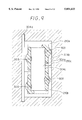
- FIG. 3 is a cross-sectional view taken along line III--III of FIG. 1;
- FIG. 4 is a view taken from the direction of arrow IV in FIG. 1;
- FIG. 5 is a perspective view of packing before dividing it according to the first embodiment
- FIG. 6 is a perspective view of the packing after dividing it according to the first embodiment
- FIG. 7 is a cross-sectional view taken along the parting surface of a mold for molding resin when the packing is disposed on the mold according to the first embodiment
- FIGS. 8A-BD are cross-sectional views taken along line VIII--VIII of FIG. 7 to show clamping conditions according to the embodiment
- FIG. 9 is a cross-sectional view of a damper during a resin filling process according to the first embodiment
- FIG. 10 is another cross-sectional view of a damper during a resin filling process according to the first embodiment
- FIGS. 11A-11C are cross-sectional views taken along line XI--XI of FIG. 7 showing stages in the resin filling process according to the first embodiment
- FIG. 12 is a perspective view explaining how to cut the packing in the first embodiment
- FIG. 13 is a perspective view of a second embodiment of the present invention.
- FIG. 14 is a perspective view of a resin-molded product for controlling air flow according to the prior art.
- FIG. 2 is an overall diagram of an automotive air conditioner using a damper according to the first embodiment as an air flow control damper.
- an inside/outside air switching portion 100 has an outside air inlet 100a and an inside air inlet 100c at an upper portion thereof.
- An inside/outside air switching damper 101 for opening and closing the outside air inlet 100a and the inside air inlet 100c is disposed in the inside/outside air switching portion 100.
- a heater core 102 has an air mixing damper 103 upstream therefrom for adjusting the amount of air passing through the heater core 102.
- air temperature inside a vehicle passenger compartment can be adjusted by adjusting the air mixing damper 103.
- a switching portion 104 for vents to the passenger compartment has a defroster outlet 105 at the upper portion thereof for eliminating cloudiness of the front glass.
- a face air outlet 106 is provided for blowing the air toward the upper part of a passenger's body.
- a foot air outlet 107 for blowing out the air toward the lower part of the passenger's body is disposed at the lower portion of the switching portion 104.
- Dampers 108 and 109 switchably control outlets 105 and 106, and 107, respectively.
- FIG. 1 shows the structure of the damper 101 according to the present invention in greater detail.
- a damper body 200 is molded with thermoplastic synthetic resin (for example, polypropylene or nylon).
- a shaft 203 as a rotational axis of the damper 101 is integrally molded with the damper body 200.
- the damper 101 rotates on the shaft 203 to open and close the outside air inlet 100a.
- Packing 210 and 211 of porous elastic material divided into the shape of a square are respectively disposed on the front and back of the damper body 200.
- Each of the packing 210 and 211 is fixed on the outer periphery of the damper body 200 like a frame and adheres to the molded damper 101.
- Marks of injected resin 200d showing the shot marks of molten thermoplastic synthetic resin (hereinafter called "resin" at the time of molding remain on the surface of the packing 210.
- portions 200c having marks of injected resin 200d are the thickest portions on the entire surface of the packing 210.
- the next thickest portions are the frame portions 200b, and the thinnest portions are the portions without the packing 210 and 211.
- the portions 200c can contribute to improving torsional rigidity and bending rigidity of the damper body 200.
- a method of manufacturing the damper 101 is hereinafter described. First, by cutting a rectangular-shaped packing material (drawn in a solid line) as shown in FIG. 5 into the shape shown with a one-dot line, two of the packing members 210a, 210b, 211a and 211b in the shape of a letter "J" are taken out of course, by cutting two such sheets, all four members 210a, 210b, 211a, 211b can be made.
- the J-shaped packing members 210a, 211a, 210b, and 211b are then disposed like a frame on the periphery of the lower mold 302 of resin-molding molds as shown in FIG. 7.
- the upper mold 301 of the resin-molding molds is placed on the lower mold 302 to pressurize and clamp the packing members 210a, 210b, 211a, and 211b as shown in FIG. 8A.
- Out of an in-mold space 304 formed with the upper and the lower molds 301 and 302 in-mold spaces 304b and 304c are occupied with the packing members 210a, 210b, 211a, and 211b.
- the parts of the in-mold space 304 are the in-mold spaces 304c, 304b and 304a.
- the in-mold space 304c is formed in the shape of a square on the entire periphery of the space for disposing the packing 210 as shown in FIG. 7.
- Molten resin is injected into the in-mold space 304 through a resin inlet 303 disposed on the upper mold 301. More specifically, four (shown in FIG. 7) resin inlets 303 are disposed on the upper mold 301 along the in-mold space 304c containing the packing 210. Two adjacent resin inlets 303 are substantially symmetrical with respect to the parting face 210c between the packing members 210a and 210b.
- the in-mold space 304 then is gradually filled with molten resin injected in the third process.
- the in-mold space 304c is hereinafter called a resin guiding space (i.e., a flow leader or flow channel).
- FIGS. 8B and 11A are schematic views of the flow of the resin.
- FIG. 9 shows an analytical result of the flow of the resin based on a finite-element method.
- FIGS. 8C and 11B are schematic views of the flow of the resin.
- FIG. 10 shows an analytical result of the flow of the resin based on a finite-element method.
- the resin-molded product is taken out of the in-mold space 304 for a finishing process to remove flash and for a product inspection process to complete the process of manufacturing the damper 101.
- J-shaped packing members 210a, 210b, 211a, and 211b are taken out by cutting two sheets of the rectangular packing material shown in FIG. 5 (with a solid line) into the shape shown with a one-dot line, which reduces waste of the packing material. If the rectangular packing material (drawn with a solid line) in FIG. 12 is cut as shown with a one-dot line, the center (the shaded portion) of the packing material is wasted. Therefore, the present embodiment can better reduce the material cost.
- the flow of the resin can be controlled so that the resin can flow into the in-mold space 304b where the packing 210 is disposed before it goes into the in-mold space 304a.
- the resin guiding space 304c the resin can be more securely controlled to flow into the in-mold space 304b where the packing 210 is disposed before flowing anywhere else.
- the packing 210 and 211 disposed in the shape of a frame can be firmly fixed to the damper body 200 at a predetermined position with predetermined dimensional accuracy, which contributes to the reduction of defective dampers 101.
- the packing 210 and 211 are strained in the direction to fill a clearance between adjacent ends of the packing members 210a and 210b or 211a and 211b with the flow of the resin as shown in FIGS. 11A-11C. Even if a small clearance (approximately 1.5-2.0 mm) between the packing members 210a and 210b as well as 211a and 211b exists when the packing members 210a, 210b, 211a, and 211b are disposed in the mold 302, the clearance can be zero at the completion of the resin filling process. The number of defective products caused by inaccurate cutting of porous elastic members and inaccurate disposition thereof can be consequently reduced.
- An allowance of asymmetry of the resin inlets 303 with respect to the parting face 210c is approximately ⁇ 20 mm according to a research of the inventors.
- Asymmetry in this case means a difference between the distance from one resin inlet 303 out of two adjacent resin inlets 303 to the parting face 210c and the distance from the other resin inlet 303 to the parting face 210c.
- FIGS. 11A-11C are schematic views of the flow of the resin illustrating this feature.
- the packing 210 and 211 are cut into a J shape, in the first embodiment, they can be cut into four portions to mold the damper 101 of the present invention as shown in FIG. 13 by using the same manufacturing method as in the first embodiment instead of cutting them into a J shape.
- the in-mold space 304 does not necessarily have a stair-like shape as shown in FIG. 8A, but can be formed to increase its thickness continuously from the center to the edge to manufacture a resin-molded product of the present invention.
- the method of manufacturing a resin-molded product according to the present invention does not have to be limited to manufacture a resin-molded product for controlling the flow of the air; rather, it is also applicable to the manufacture of resin-molded products for controlling other fluids (for example, water or oil).
- the shape of the resin-molded product molded according to the manufacturing method specified in the present invention does not have to be limited to the shape of a damper shown in FIG. 1 but can be a curved surface or a disc shape.
- the present invention can be employed for manufacturing the indicator panel of a vehicle and also for fixing porous members on the back of the indicator panel.
- the fixing position of the packing does not necessarily have to be necessarily at the outer periphery of the body of the resin-molded product as shown in the first and second embodiments. Even if the packing is fixed on other positions (for example, only the center or only on one side of the body of a resin-molded product), the manufacturing method specified in the present invention can be employed.
- the manufacturing method of the present invention can be also applied to manufacture a resin-molded product where the packing is disposed only on one surface of the body of the resin-molded product.
- packing can be cut not only into two "J" shapes as shown in FIG. 1 or into four linear portions as shown in FIG. 13 but also can be cut into six or eight linear portions.
- a resin guiding space can be disposed along the edge of the packing at the portion where packing is not disposed.
Landscapes
- Engineering & Computer Science (AREA)
- Mechanical Engineering (AREA)
- Physics & Mathematics (AREA)
- Thermal Sciences (AREA)
- Manufacturing & Machinery (AREA)
- General Engineering & Computer Science (AREA)
- Injection Moulding Of Plastics Or The Like (AREA)
- Air-Conditioning For Vehicles (AREA)
- Moulds For Moulding Plastics Or The Like (AREA)
Applications Claiming Priority (2)
| Application Number | Priority Date | Filing Date | Title |
|---|---|---|---|
| JP11740195A JP3289546B2 (ja) | 1995-05-16 | 1995-05-16 | 樹脂成形品とその製造方法 |
| JP7-117401 | 1995-05-16 |
Publications (1)
| Publication Number | Publication Date |
|---|---|
| US5851633A true US5851633A (en) | 1998-12-22 |
Family
ID=14710744
Family Applications (1)
| Application Number | Title | Priority Date | Filing Date |
|---|---|---|---|
| US08/648,706 Expired - Lifetime US5851633A (en) | 1995-05-16 | 1996-05-16 | Resin-molded product and method of manufacturing the same |
Country Status (5)
| Country | Link |
|---|---|
| US (1) | US5851633A (de) |
| EP (1) | EP0743155B1 (de) |
| JP (1) | JP3289546B2 (de) |
| KR (1) | KR100198280B1 (de) |
| DE (1) | DE69623172T2 (de) |
Families Citing this family (5)
| Publication number | Priority date | Publication date | Assignee | Title |
|---|---|---|---|---|
| JPH11254457A (ja) | 1998-03-12 | 1999-09-21 | Idemitsu Petrochem Co Ltd | 積層成形品の成形用金型および積層成形品の製造方法 |
| FR2784612B1 (fr) * | 1998-10-14 | 2000-12-15 | Groupe Neyr | Procede pour la fabrication de pieces moulees recouvertes d'une couche de materiau souple et dotees de nervures |
| JP2003127639A (ja) * | 2001-10-19 | 2003-05-08 | Inoac Corp | エアコンダンパー |
| JP2009168311A (ja) * | 2008-01-15 | 2009-07-30 | Sanden Corp | 熱交換器のシール構造 |
| KR101481692B1 (ko) * | 2008-05-01 | 2015-01-13 | 한라비스테온공조 주식회사 | 자동차 공기조화장치용 도어 |
Citations (7)
| Publication number | Priority date | Publication date | Assignee | Title |
|---|---|---|---|---|
| US3901964A (en) * | 1971-05-24 | 1975-08-26 | Arco Ind Corp | Method of making a plastic butterfly valve vane with peripheral seal |
| DE3836541A1 (de) * | 1988-10-27 | 1990-05-03 | Irbit Research & Consulting Ag | Klappe fuer lueftungskanaele |
| EP0380385A1 (de) * | 1989-01-24 | 1990-08-01 | Hutchinson | Verfahren zum Herstellen von Dichtungen, insbesondere Gleitführungen für Automobilfensterscheiben |
| US4994226A (en) * | 1986-11-22 | 1991-02-19 | Nippondenso Co., Ltd. | Method of producing synthetic resin made articles having porous elastic member |
| EP0475198A2 (de) * | 1990-08-29 | 1992-03-18 | Toyoda Gosei Co., Ltd. | Formpressen eines Formkörpers aus einer Folie und einer Harzschicht, und so hergestelltes Erzeugnis |
| EP0676267A1 (de) * | 1994-04-04 | 1995-10-11 | Toyoda Gosei Co., Ltd. | Verfahren zum Formen von Kunstharz |
| US5690881A (en) * | 1994-05-13 | 1997-11-25 | Nippondenso Co., Ltd. | Manufacturing method of resin damper having foamed resin seal material |
Family Cites Families (2)
| Publication number | Priority date | Publication date | Assignee | Title |
|---|---|---|---|---|
| JPS5962776A (ja) * | 1982-10-01 | 1984-04-10 | Nissan Motor Co Ltd | 車両用空調装置のドア構造 |
| JPS6368420A (ja) * | 1986-09-08 | 1988-03-28 | Nippon Plast Co Ltd | シヤツタ−バルブの成形方法 |
-
1995
- 1995-05-16 JP JP11740195A patent/JP3289546B2/ja not_active Expired - Fee Related
-
1996
- 1996-05-15 EP EP96107769A patent/EP0743155B1/de not_active Expired - Lifetime
- 1996-05-15 DE DE69623172T patent/DE69623172T2/de not_active Expired - Lifetime
- 1996-05-16 US US08/648,706 patent/US5851633A/en not_active Expired - Lifetime
- 1996-05-16 KR KR1019960016487A patent/KR100198280B1/ko not_active Expired - Fee Related
Patent Citations (7)
| Publication number | Priority date | Publication date | Assignee | Title |
|---|---|---|---|---|
| US3901964A (en) * | 1971-05-24 | 1975-08-26 | Arco Ind Corp | Method of making a plastic butterfly valve vane with peripheral seal |
| US4994226A (en) * | 1986-11-22 | 1991-02-19 | Nippondenso Co., Ltd. | Method of producing synthetic resin made articles having porous elastic member |
| DE3836541A1 (de) * | 1988-10-27 | 1990-05-03 | Irbit Research & Consulting Ag | Klappe fuer lueftungskanaele |
| EP0380385A1 (de) * | 1989-01-24 | 1990-08-01 | Hutchinson | Verfahren zum Herstellen von Dichtungen, insbesondere Gleitführungen für Automobilfensterscheiben |
| EP0475198A2 (de) * | 1990-08-29 | 1992-03-18 | Toyoda Gosei Co., Ltd. | Formpressen eines Formkörpers aus einer Folie und einer Harzschicht, und so hergestelltes Erzeugnis |
| EP0676267A1 (de) * | 1994-04-04 | 1995-10-11 | Toyoda Gosei Co., Ltd. | Verfahren zum Formen von Kunstharz |
| US5690881A (en) * | 1994-05-13 | 1997-11-25 | Nippondenso Co., Ltd. | Manufacturing method of resin damper having foamed resin seal material |
Non-Patent Citations (4)
| Title |
|---|
| Patent Abstracts of Japan: vol. 008, No. 166 (M 314), Aug. 1984: Re: JP 59 062776 A (Nissan Jidosha KK; Others:01), Apr. 1984: *Abstract; Figures*. * |
| Patent Abstracts of Japan: vol. 008, No. 166 (M-314), Aug. 1984: Re: JP 59 062776 A (Nissan Jidosha KK; Others:01), Apr. 1984: *Abstract; Figures*. |
| Patent Abstracts of Japan; vol. 012, No. 292 (M 792), Aug. 1988; Re: JP 63 068420 A (Nippon Plast Co., Ltd.) Mar. 1988: *Abstract; Figures 1 4,7*. * |
| Patent Abstracts of Japan; vol. 012, No. 292 (M-792), Aug. 1988; Re: JP 63 068420 A (Nippon Plast Co., Ltd.) Mar. 1988: *Abstract; Figures 1-4,7*. |
Also Published As
| Publication number | Publication date |
|---|---|
| DE69623172T2 (de) | 2003-04-03 |
| JP3289546B2 (ja) | 2002-06-10 |
| EP0743155B1 (de) | 2002-08-28 |
| JPH08309786A (ja) | 1996-11-26 |
| EP0743155A3 (de) | 1997-06-18 |
| KR100198280B1 (ko) | 1999-06-15 |
| DE69623172D1 (de) | 2002-10-02 |
| EP0743155A2 (de) | 1996-11-20 |
| KR960040612A (ko) | 1996-12-17 |
Similar Documents
| Publication | Publication Date | Title |
|---|---|---|
| EP0983885B1 (de) | Luftsteuervorrichtung für Klimaanlage | |
| US20040157013A1 (en) | Weather strip | |
| US5851633A (en) | Resin-molded product and method of manufacturing the same | |
| US6641768B2 (en) | Method for manufacturing an air passage switching door | |
| US6523805B2 (en) | Air passage switching door | |
| EP0673742B1 (de) | Verfahren zum Formen eines Elementes aus Kunststoff auf einer Glasplatte | |
| JPH06254915A (ja) | スピーカグリル一体成形法 | |
| KR101933928B1 (ko) | 핫 스탬핑 금형 | |
| JP3582262B2 (ja) | 樹脂ケーシングおよびその製造方法 | |
| JP4975313B2 (ja) | 車両用カウルトップカバー | |
| JP3979773B2 (ja) | 樹脂成形品の成形方法及び装置 | |
| US6758738B1 (en) | Damper with integral seal | |
| JP3780652B2 (ja) | 空気調和装置 | |
| US20040212127A1 (en) | Method for producing weather strip for motor vehicle | |
| US20180243959A1 (en) | Injection-moulding tool for producing a plastics component | |
| JP3689676B2 (ja) | 樹脂成形品 | |
| GB2355427A (en) | An injection moulded ventilation flap and a method of moulding | |
| KR20170083669A (ko) | 차량용 공조장치의 공조케이스 | |
| JPH1148765A (ja) | 車両用換気装置 | |
| KR200311798Y1 (ko) | 자동차용 공기조절장치의 도어판넬 | |
| JPH04269522A (ja) | モールディング | |
| JP2010023630A (ja) | ダクトの製造方法及びダクト | |
| JPH0825403A (ja) | 樹脂成形品の製造方法 | |
| JPS6068917A (ja) | モ−ルデイングの製造方法 | |
| JPH03258512A (ja) | 屈曲パイプの製造方法 |
Legal Events
| Date | Code | Title | Description |
|---|---|---|---|
| AS | Assignment |
Owner name: NIPPONDENSO CO., LTD., JAPAN Free format text: ASSIGNMENT OF ASSIGNORS INTEREST;ASSIGNORS:KAMIYA, CHIHARU;KANAI, YOSHIHIDE;REEL/FRAME:007995/0665 Effective date: 19960419 Owner name: SHIMIZU INDUSTRY CO., LTD., JAPAN Free format text: ASSIGNMENT OF ASSIGNORS INTEREST;ASSIGNORS:KAMIYA, CHIHARU;KANAI, YOSHIHIDE;REEL/FRAME:007995/0665 Effective date: 19960419 |
|
| STCF | Information on status: patent grant |
Free format text: PATENTED CASE |
|
| FEPP | Fee payment procedure |
Free format text: PAYOR NUMBER ASSIGNED (ORIGINAL EVENT CODE: ASPN); ENTITY STATUS OF PATENT OWNER: LARGE ENTITY |
|
| FPAY | Fee payment |
Year of fee payment: 4 |
|
| FPAY | Fee payment |
Year of fee payment: 8 |
|
| FPAY | Fee payment |
Year of fee payment: 12 |