US5680244A - Scanning optical system - Google Patents
Scanning optical system Download PDFInfo
- Publication number
- US5680244A US5680244A US08/354,604 US35460494A US5680244A US 5680244 A US5680244 A US 5680244A US 35460494 A US35460494 A US 35460494A US 5680244 A US5680244 A US 5680244A
- Authority
- US
- United States
- Prior art keywords
- lens
- scanning
- deflector
- sup
- lens element
- Prior art date
- Legal status (The legal status is an assumption and is not a legal conclusion. Google has not performed a legal analysis and makes no representation as to the accuracy of the status listed.)
- Expired - Lifetime
Links
Images


Classifications
-
- G—PHYSICS
- G02—OPTICS
- G02B—OPTICAL ELEMENTS, SYSTEMS OR APPARATUS
- G02B26/00—Optical devices or arrangements for the control of light using movable or deformable optical elements
- G02B26/08—Optical devices or arrangements for the control of light using movable or deformable optical elements for controlling the direction of light
- G02B26/10—Scanning systems
- G02B26/12—Scanning systems using multifaceted mirrors
- G02B26/125—Details of the optical system between the polygonal mirror and the image plane
Definitions
- the present invention relates to a scanning optical system, and more specifically, to a scanning optical system which forms a beam deflected at a uniform angular velocity by a deflector on a predetermined surface to scan the surface substantially at a uniform velocity.
- a divergent beam irradiated from a laser light source is transformed into a parallel beam by a collimator lens, etc., and is then deflected at a uniform angular velocity by a deflector such as a polygonal mirror.
- the laser beam spot is formed into an image on a scanned surface by a scanning lens system, and the scanned surface is scanned substantially at a uniform velocity.
- the scanning lens used for this purpose is provided with an f ⁇ characteristic.
- f is a focal length of the scanning lens.
- the angle ⁇ of view is an angle of the light beam deflected by the deflector to the optical axis of the scanning lens.
- the angle ⁇ of view will hereinafter be referred to as a deflection angle.
- a scanning lens is designed so that the scanning width necessary for the scanning optical system is the maximum image height.
- the maximum image height is an image height at the scanning start position and at the scanning end position on the scanned surface.
- the maximum height will hereinafter be represented by Y' max .
- the scanning width is the maximum printable sheet width.
- the maximum image height Y' max is defined by the focal length f and the maximum deflection angle ⁇ (this deflection angle will hereinafter be referred to as a maximum deflection angle ⁇ max ).
- the increase of the maximum deflection angle ⁇ max is limited because of aberration correction.
- the scanning lens having the f ⁇ characteristic as the total length decreases, the focal length f of the scanning lens decreases and the maximum deflection angle ⁇ max increases, so that a beam incident on the scanning lens having a high curvature is largely bent inward (so that the angle of the beam to the optical axis decreases) after it is incident on the scanning lens.
- the size of the deflector is largely increased or the speed of rotation of the deflector is largely increased.
- the maximum deflection angle ⁇ max is increased, the main scanning direction width of the reflection area per one deflection surface of the deflector increases, so that the size of the deflector increases.
- the scanning speed is proportional to the number of surfaces of the polygonal mirror and the rotation speed of the polygonal mirror. If the number of surfaces of the polygonal mirror is increased to obtain a predetermined scanning speed, the size of the polygonal mirror is also largely increased. If a polygonal mirror having a small number of surfaces is used to reduce the size, a rotary motor having an extremely high rotation speed is required, which results in an increase in cost.
- a scanning optical system which scans the scanned surface by making incident on the scanning lens not a parallel beam but a convergent beams having its natural convergence point located on the rear side (plus side) of the scanned surface.
- U.S. patent applications Ser. Nos. 5,111,216 and 5,128,795 enable the correction of distortion and field curvature by using only one lens with respect to a beam in the vicinity of the maximum deflection angle by providing the power arrangement in the main scanning direction not only to the refractive power of the scanning lens in the main scanning direction but also to the convergent beam.
- an image surface shift amount (hereinafter referred to as "image surface shift”) ⁇ BF in the main scanning direction due to a temperature variation at a focal length f M is given by the following expression (a): ##EQU1## where ⁇ is a magnification of a scanning lens in the main scanning direction, n is a refractive index of the scanning lens, ⁇ n/ ⁇ t is a refractive index variation due to a temperature variation of the scanning lens, ⁇ is a linear expansion coefficient of the scanning lens, f M is a focal length of the scanning lens in the main scanning direction, and ⁇ t is a temperature variation amount of the scanning lens.
- the value of ##EQU2## of the expression (a) depends on the material of the scanning lens. While this value is approximately ⁇ 0.5 ⁇ 10 -5 when the material is glass, when the material is resin, the value is approximately ⁇ 30 ⁇ 10 -5 , which is approximately 50 times that of glass material.
- Resin-made scanning lenses are easily processed to have aspherical surfaces since they can be made by injection molding. Thereby, the performance of the lenses can be improved and the manufacture of the lenses can be performed at a lower cost than conventional glass-made lenses.
- a scanning optical system using a resin-made scanning lens is advantageous in both performance and cost compared to a scanning lens using a glass-made scanning lens.
- Japanese Laid-open Patent Applications Nos. H4-153616, H4-110817 and U.S. Pat. No. 5,111,219, etc. disclosed scanning optical-systems where a resin material with a refractive index n of approximately 1.6 can be used as it is for the scanning lens.
- the beam diameter on the image surface is comparatively large because of the effect of coma, the effect that the image surface shift due to a temperature variation is reduced is not very large although the fact that (1- ⁇ ) is small contributes to the reduction in size of a scanning optical system by using a scanning lens including one lens element. Since the scanning lens includes only one lens element, the surface of the lens is of a complicated configuration having an inflection point, etc. This makes the processing of the scanning lens difficult.
- An object of the present invention is to provide a scanning optical system with its total length being reduced and with aberrations being excellently corrected irrespective of the size of the maximum deflection angle.
- An another object of the present invention is to provide a high-performance scanning optical system where a performance variation such as the image surface shift due to a temperature variation is small even though a resin-made scanning lens is used.
- FIG. 1 shows the lens arrangement and optical paths of a first embodiment of the present invention
- FIG. 2 shows the lens arrangement and optical paths of a second embodiment of the present invention
- FIG. 3 shows the lens arrangement and optical paths of a third embodiment of the present invention
- FIG. 4 shows the lens arrangement and optical paths of a fourth embodiment of the present invention
- FIG. 5 shows the lens arrangement and optical paths of a fifth embodiment of the present invention
- FIG. 6 shows the lens arrangement and optical paths of a sixth embodiment of the present invention
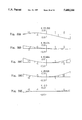
- FIG. 7 shows the lens arrangement and optical paths of a seventh embodiment of the present invention
- FIG. 8 shows the lens arrangement and optical paths of an eighth embodiment of the present invention.
- FIG. 9 shows the lens arrangement and optical paths of a ninth embodiment of the present invention.
- FIG. 10 shows the lens arrangement and optical paths of a tenth embodiment of the present invention
- FIGS. 11A to 11C show aberration curves of the first embodiment of the present invention
- FIGS. 12A to 12C show aberration curves of the second embodiment of the present invention.
- FIGS. 13A to 13C show aberration curves of the third embodiment of the present invention.
- FIGS. 14A to 14C show aberration curves of the fourth embodiment of the present invention.
- FIGS. 15A to 15C show aberration curves of the fifth embodiment of the present invention.
- FIGS. 16A to 16C show aberration curves of the sixth embodiment of the present invention.
- FIGS. 17A to 17C show aberration curves of the seventh embodiment of the present invention.
- FIGS. 18A to 18C show aberration curves of the eighth embodiment of the present invention.
- FIGS. 19A to 19C show aberration curves of the ninth embodiment of the present invention.
- FIGS. 20A to 20C show aberration curves of the tenth embodiment of the present invention.
- FIGS. 21A to 21E show lateral aberration curves of the first embodiment of the present invention
- FIGS. 22A to 22E show lateral aberration curves of the second embodiment of the present invention.
- FIGS. 23A to 23E show lateral aberration curves of the third embodiment of the present invention.
- FIGS. 24A to 24E show lateral aberration curves of the fourth embodiment of the present invention.
- FIGS. 25A to 25E show lateral aberration curves of the fifth embodiment of the present invention.
- FIGS. 26A to 26E show lateral aberration curves of the sixth embodiment of the present invention.
- FIGS. 27A to 27E show lateral aberration curves of the seventh embodiment of the present invention.
- FIGS. 28A to 28E show lateral aberration curves of the eighth embodiment of the present invention.
- FIGS. 29A to 29E show lateral aberration curves of the ninth embodiment of the present invention.
- FIGS. 30A to 30E show lateral aberration curves of the tenth embodiment of the present invention.
- FIG. 31 shows the schematic arrangement and optical paths of the entire scanning optical system embodying the present invention.
- FIG. 32 is a view of assistance in explaining the reference designations used in the description of the present invention.
- FIGS. 33A to 33I show optical paths when a distance S1 is varied in the present invention
- FIG. 34 shows the cross-section in the main scanning direction of a scanning optical system according to the present invention
- FIG. 35 shows the cross-section in the sub scanning direction of the scanning optical system according to the present invention.
- FIG. 36 is a cross-sectional view showing the main scanning direction lens arrangement of a first embodiment of the present invention.
- FIG. 37 shows field curvature of the first embodiment of the present invention
- FIG. 38 shows the f ⁇ characteristic of the first embodiment of the present invention
- FIGS. 39A to 39E show lateral aberration curves of the first embodiment of the present invention.
- FIG. 40 is a cross-sectional view showing the main scanning direction lens arrangement of a second embodiment of the present invention.
- FIG. 41 shows field curvature of the second embodiment of the present invention.
- FIG. 42 shows the f ⁇ characteristic of the second embodiment of the present invention.
- FIGS. 43A to 43E show lateral aberration curves of the second embodiment of the present invention.
- FIG. 44 is a cross-sectional view showing the main scanning direction lens arrangement of a third embodiment of the present invention.
- FIG. 45 shows field curvature of the third embodiment of the present invention.
- FIG. 46 shows the f ⁇ characteristic of the third embodiment of the present invention.
- FIGS. 47A to 47E show lateral aberration curves of the third embodiment of the present invention.
- FIG. 48 is a cross-sectional view showing the main scanning direction lens arrangement of a fourth embodiment of the present invention.
- FIG. 49 shows field curvature of the fourth embodiment of the present invention.
- FIG. 50 shows the f ⁇ characteristic of the fourth embodiment of the present invention.
- FIGS. 51A to 51E show lateral aberration curves of the fourth embodiment of the present invention.
- FIG. 52 is a cross-sectional view showing the main scanning direction lens arrangement of a fifth embodiment of the present invention.
- FIG. 53 shows field curvature of the fifth embodiment of the present invention.
- FIG. 54 shows the f ⁇ characteristic of the fifth embodiment of the present invention.
- FIGS. 55A to 55E show lateral aberration curves of the fifth embodiment of the present invention.
- FIG. 56 is a view of assistance in explaining a deformed toric surface of the scanning lens incorporated in the present invention.
- a scanning optical system of the present invention is provided with a deflector.
- a convergent beam deflected by the deflector at a uniform angular velocity is formed into an image on a scanned surface.
- the scanned surface is scanned substantially at a uniform velocity.
- the scanning lens includes from the deflector side a negative lens element and at least one other lens element.
- the convergent beam is incident on a surface of the negative lens element which faces the deflector. Further, the following conditions (1) to (3) are fulfilled:
- the scanning lens of the present invention includes from the deflector side a negative lens element and at least one other lens element will be described in more detail.
- the deflector side lens element is a positive lens
- the correction of distortion i.e. correction of distortion for uniform velocity scanning
- the correction of aberration mainly, correction of distortion for uniform velocity scanning
- at least two lenses are provided.
- the deflector side lens element is a positive lens
- the scanning lens is designed so that the convergent beam is incident on the surface of the negative lens element which faces the deflector.
- the scanning lens needs to have a strong positive power, and if the scanning lens has a strong positive power, the aberration correction will be difficult and the reduction in total length will be difficult.
- the scanning lens for converging the beam is provided with no positive power in order that the width of a beam incident on the scanning lens is transformed into a spot size in accordance with the image density on the scanned surface by making a strong convergent beam incident on the scanning lens.
- the focal length of the scanning lens is negative (negative power) or infinite (null power). Consequently, unlike the scanning lens having a positive focal length, the correction of aberration is not difficult although the total length is reduced, and aberrations (e.g. distortion, field curvature, astigmatism, coma, etc.) can excellently be corrected.
- the maximum image height Y' max can be set to a higher value by using a stronger convergent beam to shift the natural convergence point of the convergent beam toward the deflector side.
- the condition (1) is effective in reducing the total length.
- the focal length of the scanning lens is positive, so that the correction of aberrations of the beam in the vicinity of the maximum deflection angle is difficult even if the maximum deflection angle ⁇ max is increased and the focal length is decreased to reduce the total length.
- the conditions (2) and (3) are conditions for scanning the scanned surface at a uniform velocity with a beam deflected on the scanned surface at a uniform angular velocity to form the beam into an image on the scanned surface.
- C defined by the condition (3), is a distance from the deflection surface to a thin lens when the scanning lens is represented as one thin lens. Therefore, C can be defined by the condition (3) with respect to any of the beam scanning systems using a convergent, a divergent and a parallel beam, respectively.
- the scanning lens having the f ⁇ characteristic fulfills the following condition (5):
- C' is a distance from the deflection surface to the rear principal point of the scanning lens (in the scanning system using a parallel beam), and L is the total length.
- FIGS. 33A to 33I show variation in beam condition (parallel, divergent, convergent) caused by varying the distance from a light emission point (e.g. laser diode) and the collimator lens when the total length L is fixed.
- DS is the deflection surface
- SL is the scanning lens
- OS is the object surface
- IS is the image surface.
- the focal length f of the scanning lens SL is shorter than the total length L and f>0. Therefore, after converged and formed into an image, the beam is diverged and incident on the scanning lens SL, so that a thick beam is incident on a lens surface having a high curvature. Further, the beam having exited from the scanning lens SL is formed into an image on the scanned surface (k ⁇ 0) after crossing the optical axis, the beam is largely bent at the last surface of the lens. As a result, the correction of aberrations is difficult.
- the focal length f is long compared to the case where a parallel beam is incident and the proportional constant k can be increased, so that the total length L can be decreased to be smaller than that of a scanning lens SL having the f ⁇ characteristic.
- the scanning lens SL is provided with a positive power for converging the beam, so that it is difficult to correct aberrations in the vicinity of the maximum deflection angle.
- the focal length f is f ⁇ 0 and the value of k is higher than when L ⁇ Si ⁇ , so that the total length L can further be reduced. Even if the maximum deflection angle ⁇ max is fixed, the total length L can be reduced by letting S1 approach C. Since the scanning lens SL has a negative power at the optical axis and the absolute value of the negative power decreases from the optical axis to the edge along the height, it is necessary to increase the number of lens elements of the scanning lens SL or to use an aspherical surface.
- the axial power of the lens is null.
- k L
- the scanning lens SL is of a configuration where a negative power increases from the center to the edge along the height.
- the value of k is higher than when L ⁇ S1 ⁇ (FIG. 33H), so that the total length L can further be reduced.
- the null power is advantageous since the shift of the image surface IS caused by variation in surface configuration and refractive index when the temperature of the scanning lens SL increases is small.
- the seventh, eighth and ninth embodiments are each a scanning optical system with a maximum image height Y' of approximately 150 and a maximum deflection angle ⁇ max of 23 degrees, and have different distances S1. By comparing these, it is understood that the total length L is reduced as S1 approaches C even if the value of k is fixed.
- the proportional constant k can be set to a high value, so that the total length L can be reduced to the utmost without any problem in aberration correction.
- a convergent beam having been incident on the scanning lens is preferably bent so that the angle of view is larger than the deflection angle ⁇ by deflecting the convergent beam at a predetermined deflection angle ⁇ by the deflector and by making the convergent beam incident on the scanning lens SL.
- the convergent beam is bent outwardly and then inwardly in the scanning lens SL before it exits from the scanning lens SL.
- the maximum deflection angle ⁇ max can be reduced. Specifically, even if the maximum deflection angle ⁇ max is reduced, a predetermined maximum image height Y' max can be obtained at a predetermined total length L. Since the main scanning direction width of the reflection surface per deflection surface of the deflector can be reduced by reducing the maximum deflection angle ⁇ max , it is unnecessary to increase the size of the deflector, and the speed of the motor for rotating the deflector can be reduced.
- the refractive index between lenses (air distance) is 1.00.
- the relationship among the deflection surface DS, the scanning lens SL, the natural convergence point OS of the beam, the image surface IS, C defined by the condition (3) and the total length L are shown in FIG. 32.
- C corresponds to a distance from the deflection surface of the deflector to a thin lens when the scanning lens is represented as one thin lens.
- C is defined by the above-mentioned condition (3) or the following condition (3A). Since the condition (3A) is a condition obtained in view of only axial portion of the lens and the off-axial portion is not considered, in the present invention, C is defined by the condition (3). ##EQU5##
- the surfaces marked with asterisks (*) are aspherical.
- FIG. 31 shows the entire arrangement of a scanning optical system embodying the present invention.
- a divergent beam BM1 emitted from a light source (comprising a light emitting device such as a laser diode) is converged into a convergent beam (incident light) BM2 by a converging lens 2 and then incident on a deflector (polygonal mirror) 3.
- a convergent beam BM3 (the origin is (0,0)) deflected at a uniform angular velocity by a deflector 3 rotating with (X c , Y c ) as the center of rotation is incident on the scanning lens SL.
- the natural convergence point OS of the convergent beam BM3 is located on the image side of the deflector side surface of the most deflector side lens of the scanning lens SL.
- a beam BM4 is formed into an image on a scanned surface 4 by the scanning lens SL to scan the scanned surface 4 substantially at a uniform velocity.
- the scanning optical systems of the first to tenth embodiments are provided with the deflector 3 and the scanning lens SL which forms the convergent beam BM3 deflected by the deflector 3 at a uniform angular velocity into an image on the scanned surface 4 to scan the scanned surface 4 substantially at a uniform velocity.
- the scanning lens SL includes from the deflector side a negative lens element and at least one other lens element. On the surface of the negative lens element which faces the deflector 3, the convergent beam is incident. Further, the scanning optical systems of the first to tenth embodiments fulfill the conditions (1) to (3).
- FIGS. 1 to 10 are cross-sectional views showing the main scanning direction arrangements and optical paths of the scanning lenses SL corresponding to the first to tenth embodiments.
- the reference designation J in these figures shows a deflection condition of a beam having an angle of view (deflection angle ⁇ ) defined by the following equation (9).
- the scanning lens SL of the first embodiment includes from the deflector side a negative bi-concave lens element and a positive meniscus lens element (whose image side surface is aspherical) convex to the deflector side.
- the scanning lens SL of the second embodiment includes from the deflector side a negative meniscus lens element (whose deflector side surface is aspherical) concave to the deflector side, a negative meniscus lens element concave to the image side and a positive meniscus lens element (whose image side surface is aspherical) convex to the deflector side.
- the scanning lens SL of the third embodiment includes from the deflector side a negative bi-concave lens element and a positive meniscus lens element (whose both side surfaces are aspherical) convex to the deflector side.
- the scanning lens SL of the fourth embodiment includes from the deflector side a negative meniscus lens (whose deflector side surface is aspherical) concave to the deflector side, a negative bi-concave lens element and a positive bi-convex lens element (whose image side surface is aspherical).
- the scanning lens SL of the fifth embodiment includes from the deflector side a negative bi-concave lens element (whose deflector side surface is aspherical), a negative meniscus lens element convex to the image side and a positive meniscus lens element (whose image side surface is aspherical) convex to the deflector side.
- the scanning lens SL of the sixth embodiment includes from the deflector side a negative meniscus lens element concave to the deflector side and a negative meniscus lens element (whose both side surfaces are aspherical) concave to the image side.
- the scanning lenses SL of the seventh, eighth and ninth embodiments include from the deflector side a negative meniscus lens element concave to the deflector side and a positive meniscus lens element (whose image side surface is aspherical) convex to the image side.
- the scanning lens SL of the tenth embodiment includes from the deflector side a negative meniscus lens element concave to the image side, a positive meniscus lens element (whose image side surface is aspherical) convex to the deflector side and a cylindrical lens element.
- FIGS. 11A to 11C through 20A to 20C and FIGS. 21A to 21E through FIGS. 30A to 30E show aberrations of the first to tenth embodiments.
- FIGS. 11A to 11C through 20A to 20C show aberrations (with a wavelength of 780 nm) corresponding to the first to tenth embodiments, respectively.
- the solid lines represent spherical aberration
- the broken lines SC represent sine condition
- the broken lines DT represent astigmatism on the tangential surface.
- FIGS. 21A to 21E through FIGS. 30A to 30E show lateral aberration curves on the Gaussian surface corresponding to the first to tenth embodiments, respectively.
- the focal length f of the scanning lens SL is negative (negative power) or infinite (null power) in order that the width of the beam incident on the scanning lens SL is transformed into a spot size on the scanned surface in accordance with the image density.
- the proportional constant k can be set to a high value, so that the total length is reduced to the utmost without any problem in aberration correction.
- the correction of aberration is not difficult although the total length is reduced.
- aberrations such as distortion, coma, field curvature, astigmatism, etc. are excellently corrected.
- the seventh to ninth embodiments are each a scanning optical system with a maximum image height Y' of approximately 150 and a maximum deflection angle ⁇ max of 23 degrees, and have different distances S1.
- the total length L is decreased (the total length L of the seventh embodiment is the longest) as S1 approaches C even if the value of k is almost fixed.
- the scanning optical systems of the first, third, sixth, seventh, eighth and ninth embodiments are characterized in that a convergent beam deflected at a predetermined deflection angle and incident on the scanning lens SL is bent at an angle of view greater than the deflection angle after incident on the scanning lens SL.
- the convergent beam is bent outwardly and then inwardly in the scanning lens SL before it exits from the scanning lens SL.
- the convergent beam is bent outwardly by the negative bi-concave lens element and then bent inwardly by the positive meniscus lens element convex to the deflector side.
- the maximum deflection angle ⁇ max can be reduced by bending the convergent beam in this manner. Specifically, even if the maximum deflection angle ⁇ max is reduced, a predetermined maximum image height Y' max can be obtained at a predetermined total length L. Since the main scanning direction width of the reflection surface per deflection surface of the deflector can be reduced by reducing the maximum deflection angle ⁇ max , it is unnecessary to increase the size of the deflector, and the speed of the motor (not shown) for rotating the deflector can be reduced.
- the scanning lens includes from the deflector side a negative lens element and at least one other lens element, so that distortion is excellently corrected.
- the convergent beam is incident on a surface of the negative lens element which faces the deflector, so that aberration correction is easy and the total length is reduced.
- the aberration correction is not difficult even if the total length is reduced, and aberrations (e.g. distortion, field curvature, astigmatism, coma, etc.) are excellently corrected.
- the maximum image height can be set to a higher value by shifting the natural convergence point of the convergent beam toward the deflector side, so that the total length is further reduced.
- the total length is reduced not by only increasing the maximum deflection angle but by making a strong convergent beam incident on the scanning lens. Further, the total length is reduced by making a strong convergent beam incident on the scanning lens without increasing the maximum deflection angle to reduce the total length.
- the maximum deflection angle can be decreased to decrease the main scanning direction width per deflection surface of the deflector, so that it is unnecessary to increase the size of the deflector and the speed of the motor for rotating the deflector is reduced.
- This implementation is a scanning optical system where the performance variation due to a temperature variation is small even if a resin-made scanning lens is used.
- This scanning optical system is provided with a deflector and a scanning lens which forms a convergent beam deflected by the deflector at a uniform angular velocity into an image on a scanned surface to scan the scanned surface substantially at a uniform velocity.
- the scanning lens includes from the deflector side a negative first lens element and a positive second lens element. At least one surface of the second lens element is a toric surface where the refractive power is different between the main and sub scanning directions.
- the toric surface fulfills the following condition (11):
- ⁇ is a magnification of the scanning lens in the main scanning direction.
- the condition (11) is a condition for decreasing the image surface shift amount ⁇ BF defined by the above-mentioned condition (a).
- the limit of the condition (11) is exceeded, the image surface shift amount ⁇ BF due to a temperature variation increases, so that the performance extremely deteriorates due to the temperature variation even if the aberration performance of the scanning lens is improved.
- the scanning lens preferably fulfills the following condition (12): ##EQU7## where f 1M is a focal length of the first lens element in the main scanning direction and f 2M is a focal length of the second lens element in the main scanning direction.
- the condition (12) is a condition for correcting field curvature in the main scanning direction within the limit of the condition (11). Since the first lens element has a negative refractive power, its focal length f 1M is negative. When the focal length f 1M is positive, to fulfill the condition (11), the focal length f 2M of the second lens element in the main scanning direction must take a high positive value or a low negative value. Then, however, it is difficult to correct field curvature in the main scanning direction. Even if the focal length f 1M is negative, when the limits of the condition (12) are exceeded, the focal length f 2M takes a high positive value, so that it is difficult to correct field curvature in the main scanning direction like the above case.
- the scanning lens preferably fulfills the following condition (13):
- f 1S is a focal length of the first lens element in the sub scanning direction.
- the condition (13) represents that the first lens element includes rotationally symmetric surfaces. This is because rotationally symmetric surfaces which are easy to process and measure are preferable in metal mold processing of injection-molded lenses.
- the scanning lens preferably fulfills the following condition (14): ##EQU8## where f 2S is a focal length of the second lens element in the sub scanning direction.
- the condition (14) defines the ratio between the sub scanning direction focal length of the first lens element including the rotationally symmetric surfaces and the sub scanning direction focal length f 2S of the second lens element, and is a condition for maintaining the sub scanning direction field curvature in an excellent condition. When the limits of the condition (14) are exceeded, it is difficult to correct astigmatism on the main scanning image surface and on the sub scanning image surface.
- the scanning lens preferably fulfills the following condition (15): ##EQU9##
- the condition (15) is a condition for making gentle the change of the thickness of the lens and for making excellent the image surfaces in the main and sub scanning directions. When the limits of the condition (15) are exceeded, it is difficult to process the metal mold.
- At least one surface of the second lens element is a toric surface where the refractive power is different between the main and sub scanning directions.
- the toric surface of the second lens element will be described with an extended y toric surface as a example.
- the main scanning cross section of the extended y toric surface is aspherical, and the curvature in the sub scanning direction continuously changes along the main scanning cross section.
- This toric surface is defined as a function of y and z by the following expression (A): ##EQU10##
- the extended y toric surface is obtained as a standard y toric surface to which a two-dimensional additional term A(y, z) is added.
- a curve on the main scanning cross section is a main curve C m
- a curve on the sub scanning cross section is a profile curve C p (i.e. x: along the optical axis, y: the main scanning direction, and z: the sub scanning direction)
- K and c respectively represent curvatures in the main curve direction and in the profile curve direction at the vertex (exactly, K+2a 0 .2 and c+2a 2 .0, respectively).
- 1/K is a radius of curvature of the main curve C m at the vertex
- 1/c is a radius of curvature of the profile curve C p (radius of curvature of the main curve C m in the sub scanning direction at the vertex)
- ⁇ and ⁇ respectively represent conic constants in the main curve direction and in the profile curve direction (hyperbola when negative, parabola when zero, ellipse when positive, circle when one).
- the expression (A) represents a conventional toric surface (a surface made by rotating a secondary profile curve ⁇ about an axis parallel to the y-axis with a radius of 1/K).
- d 0 is an axial distance from the deflection point on the surface of the deflector to an ith lens surface
- LB is a lens back (i.e.
- ⁇ max is an angle of view when an angle of view (deflection angle) of the deflected beam to the optical axis of the scanning lens is maximum (i.e. maximum deflection angle).
- S1 is a distance from the deflection surface to the natural convergence point of the convergent beam (convergence point of the convergent beam when no scanning lens is provided, i.e. object point).
- Y max is an image height which is maximum on the scanned surface.
- the fourth surface (r 4M , r 4S ) is the extended toric surface.
- the surfaces marked with asterisks (*) are aspherical.
- FIGS. 34 and 35 show the arrangement of the entire scanning optical system of the eleventh to fifteenth embodiments (the shown scanning lens SL is that of the eleventh embodiment).
- FIG. 34 shows the cross section in the main scanning direction
- FIG. 35 shows the cross section in the sub scanning direction.
- the scanning optical system is provided with a deflector 5 and a scanning lens SL which forms a convergent beam deflected by the deflector 5 at a uniform angular velocity into an image on a scanned surface 8 to scan the scanned surface 8 substantially at a uniform speed.
- a divergent beam emitted from a light source 1 comprising a semiconductor laser is transformed by a condenser lens 2 into a convergent beam in the main scanning direction.
- the convergent beam is a convergent beam which is condensed at a natural convergence point 10 when no scanning lens SL is provided.
- the width of the convergent beam is restricted by an aperture stop 3 so that a required beam diameter is obtained, and the beam is incident on a cylindrical lens 4 having a refractive power only in the sub scanning direction.
- the beam having exited from the cylindrical lens 4 is incident on the deflector (polygonal mirror) 5, and converged at the position of a polygonal reflection position 9 only in the sub scanning direction as shown in FIG. 35.
- the convergent beam deflected at a uniform angular velocity by the deflector 5 rotating (about an axis parallel to the sub scanning direction) at a high speed is incident on the scanning lens SL.
- the beam is transformed by the scanning lens SL into a uniform beam on an image surface 8 (i.e. the surface of a photoreceptor 8 which is the scanned surface) to scan the scanned surface 8 substantially at a uniform velocity.
- the polygonal reflection surface 9 is substantially conjugate with the scanned surface on the photoreceptor 8 because of the extended y toric surface (the fourth surface having radii of curvature of r 4M , r 4S ) included in the second lens element G2. This is in order to correct the shift of the convergence position on the photoreceptor 8 in the sub scanning direction when a slight image inclination occurs at the polygonal mirror 5.
- the scanning lens SL incorporated in the eleventh to fifteenth embodiments includes from the deflector side a negative first lens element G1 and a positive second lens element G2, both of which are made of resin. While the first lens element G1 is axially symmetric, the second lens element G2 has at the fourth surface (with radii of curvature of r 4M , r 4S ) the extended y toric surface where the refractive power is different (i.e. the radius of curvature is different) between in the main and sub scanning directions.
- the scanning lens SL includes from the deflector side the negative first lens element G1 and the positive second lens element G2 and the second lens element G2 includes the toric surface where the refractive power is different between the main and sub scanning directions, even though the performance variation due to a temperature variation is restrained, a high optical performance can be maintained to realize a high-performance scanning optical system.
- the scanning optical system suitable for the resin-made scanning lens SL when a resin material is used for the scanning lens SL, axially symmetric aspherical surfaces and toric surfaces having complicated surface configurations and advantageous in improving the performance can be formed at a low cost, so that a high-performance optical system can be realized at a low cost. Since the optical systems of the eleventh to fifteenth embodiments are designed to fulfill the above-described conditions (11) to (15), the above-mentioned advantages are obtained.
- FIGS. 36, 40, 44, 48 and 52 are cross-sectional views showing the main scanning direction arrangements of the scanning lenses SL of the eleventh to fifteenth embodiments.
- FIGS. 47, 41, 45, 49 and 53 show field curvature (with a wavelength of 780 nm) of the eleventh to fifteenth embodiments.
- the solid lines DT show field curvature in the main scanning direction.
- the broken lines DS show field curvature in the sub-scanning direction.
- FIGS. 38, 42, 46, 50 and 54 show distortion (i.e. f ⁇ characteristic with a wavelength of 780 nm) of the eleventh to fifteenth embodiments.
- FIGS. 39A to 39E, 43A to 43E, 47A to 47E, 51A to 51E and 55A to 55E show lateral aberration curves of the eleventh to fifteenth embodiments.
- the scanning lens fulfills the condition (11), even though a resin-made scanning lens is used, the performance variation such as the image surface shift due to a temperature variation is restrained. Since the scanning lens includes from the deflector side the negative first lens element and the positive second lens element and at least one surface of the second lens element is a toric surface where the refractive power is different between the main and sub scanning directions, even though the performance variation due to a temperature variation is restrained, a high optical performance is maintained, so that a high-performance scanning optical system is realized.
- the scanning optical system suitable for the resin-made scanning lens when a resin material is used for the scanning lens, axially Symmetric aspherical surfaces and toric surfaces having complicated surface configurations and advantageous in improving the performance can be formed at a low cost, so that a high-performance optical system is realized at a low cost.
Landscapes
- Physics & Mathematics (AREA)
- General Physics & Mathematics (AREA)
- Optics & Photonics (AREA)
- Mechanical Optical Scanning Systems (AREA)
- Lenses (AREA)
Priority Applications (1)
| Application Number | Priority Date | Filing Date | Title |
|---|---|---|---|
| US08/547,502 US5715079A (en) | 1993-12-16 | 1995-10-24 | Scanning optical system |
Applications Claiming Priority (3)
| Application Number | Priority Date | Filing Date | Title |
|---|---|---|---|
| JP5-316757 | 1993-12-16 | ||
| JP31675793A JP3235306B2 (ja) | 1993-12-16 | 1993-12-16 | 走査光学系 |
| JP6-195257 | 1994-08-19 |
Related Child Applications (1)
| Application Number | Title | Priority Date | Filing Date |
|---|---|---|---|
| US08/547,502 Division US5715079A (en) | 1993-12-16 | 1995-10-24 | Scanning optical system |
Publications (1)
| Publication Number | Publication Date |
|---|---|
| US5680244A true US5680244A (en) | 1997-10-21 |
Family
ID=18080587
Family Applications (2)
| Application Number | Title | Priority Date | Filing Date |
|---|---|---|---|
| US08/354,604 Expired - Lifetime US5680244A (en) | 1993-12-16 | 1994-12-13 | Scanning optical system |
| US08/547,502 Expired - Lifetime US5715079A (en) | 1993-12-16 | 1995-10-24 | Scanning optical system |
Family Applications After (1)
| Application Number | Title | Priority Date | Filing Date |
|---|---|---|---|
| US08/547,502 Expired - Lifetime US5715079A (en) | 1993-12-16 | 1995-10-24 | Scanning optical system |
Country Status (2)
| Country | Link |
|---|---|
| US (2) | US5680244A (ja) |
| JP (1) | JP3235306B2 (ja) |
Cited By (5)
| Publication number | Priority date | Publication date | Assignee | Title |
|---|---|---|---|---|
| EP1832911A1 (en) * | 2006-03-06 | 2007-09-12 | Canon Kabushiki Kaisha | Optical scanning apparatus and image forming apparatus using the same |
| US7556309B2 (en) * | 2005-03-14 | 2009-07-07 | Yanmar Co., Ltd. | Bonnet structure for working vehicle |
| US20100033793A1 (en) * | 2008-08-05 | 2010-02-11 | E-Pin Optical Industry Co., Ltd. | Two-element f-theta lens used for micro-electro mechanical system (mems) laser scanning unit |
| US20100073752A1 (en) * | 2008-08-05 | 2010-03-25 | E-Pin Optical Industry Co., Ltd. | Two-element f-theta lens used for micro-electro mechanical system (mems) laser scanning unit |
| EP4375727A1 (en) * | 2022-11-24 | 2024-05-29 | Ricoh Company, Ltd. | Projection apparatus |
Families Citing this family (13)
| Publication number | Priority date | Publication date | Assignee | Title |
|---|---|---|---|---|
| JPH08240768A (ja) * | 1995-03-02 | 1996-09-17 | Minolta Co Ltd | 走査光学系 |
| US6549227B2 (en) | 1996-07-31 | 2003-04-15 | Kabushiki Kaisha Toshiba | Multi-beam exposer unit |
| JP3771328B2 (ja) | 1996-07-31 | 2006-04-26 | 株式会社東芝 | マルチビーム露光装置 |
| JP3627781B2 (ja) * | 1997-01-29 | 2005-03-09 | コニカミノルタビジネステクノロジーズ株式会社 | レーザー走査装置 |
| KR100282264B1 (ko) * | 1998-07-01 | 2001-02-15 | 이형도 | 광주사장치 |
| JP3854779B2 (ja) * | 2000-04-13 | 2006-12-06 | キヤノン株式会社 | 光走査装置及びそれを用いた画像形成装置 |
| US7116347B2 (en) * | 2000-11-07 | 2006-10-03 | Ricoh Company, Ltd. | Optical scanning device and image forming system including the same |
| US7050082B2 (en) * | 2002-01-23 | 2006-05-23 | Ricoh Company, Ltd. | Image forming system employing effective optical scan-line control device |
| JP4006313B2 (ja) * | 2002-10-17 | 2007-11-14 | キヤノン株式会社 | 走査型表示光学系及び走査型表示装置 |
| JP2005018040A (ja) * | 2003-06-02 | 2005-01-20 | Seiko Epson Corp | 走査装置、レーザプロジェクタ、及び光学装置 |
| JP4533409B2 (ja) * | 2007-08-06 | 2010-09-01 | キヤノン株式会社 | 走査型表示光学系 |
| TWI426297B (zh) * | 2009-06-25 | 2014-02-11 | E Pin Optical Industry Co Ltd | 雷射掃描裝置之短聚光距二片式fΘ鏡片(二) |
| JP5318187B2 (ja) * | 2011-12-21 | 2013-10-16 | キヤノン株式会社 | 光走査装置及びそれを用いた画像形成装置 |
Citations (5)
| Publication number | Priority date | Publication date | Assignee | Title |
|---|---|---|---|---|
| US4953926A (en) * | 1988-03-14 | 1990-09-04 | Asahi Kogaku Kogyo Kabushiki Kaisha | Scanning optical system for use in a laser beam printer |
| JPH04110817A (ja) * | 1990-08-30 | 1992-04-13 | Canon Inc | 走査光学装置 |
| US5111219A (en) * | 1990-06-15 | 1992-05-05 | Canon Kabushiki Kaisha | Fθ lens and image apparatus using the same |
| JPH04153616A (ja) * | 1990-10-17 | 1992-05-27 | Canon Inc | 光走査光学系 |
| US5128795A (en) * | 1989-08-14 | 1992-07-07 | Ricoh Company, Ltd. | Scanning lens and scanning apparatus using scanning lens |
Family Cites Families (5)
| Publication number | Priority date | Publication date | Assignee | Title |
|---|---|---|---|---|
| JPS57144516A (en) * | 1981-03-03 | 1982-09-07 | Canon Inc | Scan optical system having fall compensating function |
| JP2702992B2 (ja) * | 1987-12-14 | 1998-01-26 | 株式会社日立製作所 | 高解像度光ビーム走査装置 |
| US5247385A (en) * | 1990-01-25 | 1993-09-21 | Ricoh Company, Ltd. | Fθ lens and lens for forming linear image |
| JP2965364B2 (ja) * | 1991-01-17 | 1999-10-18 | 株式会社リコー | 光走査方法および光走査装置 |
| US5499107A (en) * | 1991-04-30 | 1996-03-12 | Minolta Co., Ltd. | Laser beam optical scanning system |
-
1993
- 1993-12-16 JP JP31675793A patent/JP3235306B2/ja not_active Expired - Lifetime
-
1994
- 1994-12-13 US US08/354,604 patent/US5680244A/en not_active Expired - Lifetime
-
1995
- 1995-10-24 US US08/547,502 patent/US5715079A/en not_active Expired - Lifetime
Patent Citations (5)
| Publication number | Priority date | Publication date | Assignee | Title |
|---|---|---|---|---|
| US4953926A (en) * | 1988-03-14 | 1990-09-04 | Asahi Kogaku Kogyo Kabushiki Kaisha | Scanning optical system for use in a laser beam printer |
| US5128795A (en) * | 1989-08-14 | 1992-07-07 | Ricoh Company, Ltd. | Scanning lens and scanning apparatus using scanning lens |
| US5111219A (en) * | 1990-06-15 | 1992-05-05 | Canon Kabushiki Kaisha | Fθ lens and image apparatus using the same |
| JPH04110817A (ja) * | 1990-08-30 | 1992-04-13 | Canon Inc | 走査光学装置 |
| JPH04153616A (ja) * | 1990-10-17 | 1992-05-27 | Canon Inc | 光走査光学系 |
Cited By (13)
| Publication number | Priority date | Publication date | Assignee | Title |
|---|---|---|---|---|
| US7556309B2 (en) * | 2005-03-14 | 2009-07-07 | Yanmar Co., Ltd. | Bonnet structure for working vehicle |
| US7557974B2 (en) * | 2006-03-06 | 2009-07-07 | Canon Kabushiki Kaisha | Optical scanning apparatus and image forming apparatus using the same including relationship between interval between deflector and scanned surface and a natural convergent point |
| US7450284B2 (en) | 2006-03-06 | 2008-11-11 | Canon Kabushiki Kaisha | Optical scanning apparatus and image forming apparatus using the same including relationship between interval between deflector and scanned surface and a natural convergent point |
| KR100873406B1 (ko) * | 2006-03-06 | 2008-12-11 | 캐논 가부시끼가이샤 | 광 주사 장치 및 그것을 이용한 화상 형성 장치 |
| US20090022518A1 (en) * | 2006-03-06 | 2009-01-22 | Canon Kabushiki Kaisha | Optical scanning apparatus and image forming apparatus using the same |
| US20080137164A1 (en) * | 2006-03-06 | 2008-06-12 | Yuichi Tomioka | Optical scanning apparatus and image forming apparatus using the same |
| EP1832911A1 (en) * | 2006-03-06 | 2007-09-12 | Canon Kabushiki Kaisha | Optical scanning apparatus and image forming apparatus using the same |
| CN100520489C (zh) * | 2006-03-06 | 2009-07-29 | 佳能株式会社 | 光学扫描设备以及使用该光学扫描设备的图像形成设备 |
| US20100033793A1 (en) * | 2008-08-05 | 2010-02-11 | E-Pin Optical Industry Co., Ltd. | Two-element f-theta lens used for micro-electro mechanical system (mems) laser scanning unit |
| US20100073752A1 (en) * | 2008-08-05 | 2010-03-25 | E-Pin Optical Industry Co., Ltd. | Two-element f-theta lens used for micro-electro mechanical system (mems) laser scanning unit |
| US8031387B2 (en) * | 2008-08-05 | 2011-10-04 | E-Pin Optical Industry Co., Ltd. | Two-element fθ lens used for micro-electro mechanical system (MEMS) laser scanning unit |
| US8031388B2 (en) * | 2008-08-05 | 2011-10-04 | E-Pin Optical Industry Co., Ltd. | Two-element f-θ lens used for micro-electro mechanical system (MEMS) laser scanning unit |
| EP4375727A1 (en) * | 2022-11-24 | 2024-05-29 | Ricoh Company, Ltd. | Projection apparatus |
Also Published As
| Publication number | Publication date |
|---|---|
| US5715079A (en) | 1998-02-03 |
| JPH07168094A (ja) | 1995-07-04 |
| JP3235306B2 (ja) | 2001-12-04 |
Similar Documents
| Publication | Publication Date | Title |
|---|---|---|
| US5680244A (en) | Scanning optical system | |
| US6166843A (en) | Optical scanning system with single element refractive/reflective fθ lens and single element refractive/reflective fθ lens | |
| US5179465A (en) | Optical system for light beam scanning | |
| US5973813A (en) | Reflection type optical scanning system | |
| US5563729A (en) | Image forming light scanning apparatus | |
| EP0476698B1 (en) | Optical beam scanning system | |
| US5808773A (en) | Scanning optical system | |
| JP3134906B2 (ja) | ビーム走査装置 | |
| JP3221244B2 (ja) | 走査光学系 | |
| EP0441350A2 (en) | Optical system for light beam scanning | |
| US6144477A (en) | Scanning optical system | |
| JP3804886B2 (ja) | 光走査装置用結像光学系 | |
| JP3051671B2 (ja) | 光走査用レンズおよび光走査装置 | |
| US20030146376A1 (en) | Scanning optical system | |
| JP3585636B2 (ja) | 光走査装置用集光光学系 | |
| JP3484308B2 (ja) | 走査結像レンズ系 | |
| US5673137A (en) | Condenser optical system for light scanning system | |
| JP3404204B2 (ja) | 光走査用レンズおよび走査結像レンズおよび光走査装置 | |
| JPH10213740A (ja) | レーザー走査装置 | |
| US5442477A (en) | Optical scanning system | |
| JP3492911B2 (ja) | 光走査装置 | |
| JP3717656B2 (ja) | 光走査装置および走査結像レンズ | |
| JP3100760B2 (ja) | 温度補償された走査光学系 | |
| JPH06308382A (ja) | 光走査光学系 | |
| JP3759220B2 (ja) | 光走査装置用集光光学系 |
Legal Events
| Date | Code | Title | Description |
|---|---|---|---|
| AS | Assignment |
Owner name: MINOLTA CO., LTD., JAPAN Free format text: ASSIGNMENT OF ASSIGNORS INTEREST;ASSIGNORS:ONO, SATORU;NAIKI, TOSHIO;REEL/FRAME:007278/0984 Effective date: 19941201 |
|
| STCF | Information on status: patent grant |
Free format text: PATENTED CASE |
|
| FEPP | Fee payment procedure |
Free format text: PAYOR NUMBER ASSIGNED (ORIGINAL EVENT CODE: ASPN); ENTITY STATUS OF PATENT OWNER: LARGE ENTITY |
|
| CC | Certificate of correction | ||
| FPAY | Fee payment |
Year of fee payment: 4 |
|
| FPAY | Fee payment |
Year of fee payment: 8 |
|
| FPAY | Fee payment |
Year of fee payment: 12 |