US5384522A - Braking control system for an electric vehicle - Google Patents
Braking control system for an electric vehicle Download PDFInfo
- Publication number
- US5384522A US5384522A US07/866,339 US86633992A US5384522A US 5384522 A US5384522 A US 5384522A US 86633992 A US86633992 A US 86633992A US 5384522 A US5384522 A US 5384522A
- Authority
- US
- United States
- Prior art keywords
- braking
- period
- control system
- braking period
- voltage
- Prior art date
- Legal status (The legal status is an assumption and is not a legal conclusion. Google has not performed a legal analysis and makes no representation as to the accuracy of the status listed.)
- Expired - Lifetime
Links
- 230000001172 regenerating effect Effects 0.000 claims abstract description 69
- 238000000034 method Methods 0.000 claims abstract description 26
- 230000003247 decreasing effect Effects 0.000 claims description 30
- 230000001965 increasing effect Effects 0.000 claims description 24
- 230000007423 decrease Effects 0.000 claims description 10
- 230000007257 malfunction Effects 0.000 abstract description 27
- 238000001514 detection method Methods 0.000 abstract description 19
- 230000008569 process Effects 0.000 abstract description 2
- 230000001276 controlling effect Effects 0.000 description 29
- 238000010586 diagram Methods 0.000 description 28
- 230000005540 biological transmission Effects 0.000 description 26
- 238000001816 cooling Methods 0.000 description 14
- 230000005355 Hall effect Effects 0.000 description 9
- 230000001133 acceleration Effects 0.000 description 9
- 230000009467 reduction Effects 0.000 description 9
- 230000001419 dependent effect Effects 0.000 description 4
- 238000004519 manufacturing process Methods 0.000 description 4
- 239000003990 capacitor Substances 0.000 description 3
- 230000000694 effects Effects 0.000 description 3
- 230000001939 inductive effect Effects 0.000 description 3
- 238000012544 monitoring process Methods 0.000 description 3
- 230000004044 response Effects 0.000 description 3
- 239000006096 absorbing agent Substances 0.000 description 2
- 230000035939 shock Effects 0.000 description 2
- 229910000831 Steel Inorganic materials 0.000 description 1
- 230000002411 adverse Effects 0.000 description 1
- 230000033228 biological regulation Effects 0.000 description 1
- 238000010276 construction Methods 0.000 description 1
- 230000007812 deficiency Effects 0.000 description 1
- 230000002542 deteriorative effect Effects 0.000 description 1
- 230000003292 diminished effect Effects 0.000 description 1
- 230000002708 enhancing effect Effects 0.000 description 1
- 230000005669 field effect Effects 0.000 description 1
- 230000005389 magnetism Effects 0.000 description 1
- 239000000463 material Substances 0.000 description 1
- 239000002184 metal Substances 0.000 description 1
- 229910052751 metal Inorganic materials 0.000 description 1
- 238000012986 modification Methods 0.000 description 1
- 230000004048 modification Effects 0.000 description 1
- 238000005192 partition Methods 0.000 description 1
- 239000000047 product Substances 0.000 description 1
- 230000001681 protective effect Effects 0.000 description 1
- 230000001105 regulatory effect Effects 0.000 description 1
- 230000008439 repair process Effects 0.000 description 1
- 239000011347 resin Substances 0.000 description 1
- 229920005989 resin Polymers 0.000 description 1
- 239000010959 steel Substances 0.000 description 1
- 239000013589 supplement Substances 0.000 description 1
- 230000001052 transient effect Effects 0.000 description 1
- 238000004804 winding Methods 0.000 description 1
Images


Classifications
-
- B—PERFORMING OPERATIONS; TRANSPORTING
- B60—VEHICLES IN GENERAL
- B60L—PROPULSION OF ELECTRICALLY-PROPELLED VEHICLES; SUPPLYING ELECTRIC POWER FOR AUXILIARY EQUIPMENT OF ELECTRICALLY-PROPELLED VEHICLES; ELECTRODYNAMIC BRAKE SYSTEMS FOR VEHICLES IN GENERAL; MAGNETIC SUSPENSION OR LEVITATION FOR VEHICLES; MONITORING OPERATING VARIABLES OF ELECTRICALLY-PROPELLED VEHICLES; ELECTRIC SAFETY DEVICES FOR ELECTRICALLY-PROPELLED VEHICLES
- B60L3/00—Electric devices on electrically-propelled vehicles for safety purposes; Monitoring operating variables, e.g. speed, deceleration or energy consumption
- B60L3/0023—Detecting, eliminating, remedying or compensating for drive train abnormalities, e.g. failures within the drive train
-
- B—PERFORMING OPERATIONS; TRANSPORTING
- B60—VEHICLES IN GENERAL
- B60L—PROPULSION OF ELECTRICALLY-PROPELLED VEHICLES; SUPPLYING ELECTRIC POWER FOR AUXILIARY EQUIPMENT OF ELECTRICALLY-PROPELLED VEHICLES; ELECTRODYNAMIC BRAKE SYSTEMS FOR VEHICLES IN GENERAL; MAGNETIC SUSPENSION OR LEVITATION FOR VEHICLES; MONITORING OPERATING VARIABLES OF ELECTRICALLY-PROPELLED VEHICLES; ELECTRIC SAFETY DEVICES FOR ELECTRICALLY-PROPELLED VEHICLES
- B60L50/00—Electric propulsion with power supplied within the vehicle
- B60L50/50—Electric propulsion with power supplied within the vehicle using propulsion power supplied by batteries or fuel cells
- B60L50/52—Electric propulsion with power supplied within the vehicle using propulsion power supplied by batteries or fuel cells characterised by DC-motors
-
- B—PERFORMING OPERATIONS; TRANSPORTING
- B60—VEHICLES IN GENERAL
- B60L—PROPULSION OF ELECTRICALLY-PROPELLED VEHICLES; SUPPLYING ELECTRIC POWER FOR AUXILIARY EQUIPMENT OF ELECTRICALLY-PROPELLED VEHICLES; ELECTRODYNAMIC BRAKE SYSTEMS FOR VEHICLES IN GENERAL; MAGNETIC SUSPENSION OR LEVITATION FOR VEHICLES; MONITORING OPERATING VARIABLES OF ELECTRICALLY-PROPELLED VEHICLES; ELECTRIC SAFETY DEVICES FOR ELECTRICALLY-PROPELLED VEHICLES
- B60L7/00—Electrodynamic brake systems for vehicles in general
- B60L7/10—Dynamic electric regenerative braking
-
- Y—GENERAL TAGGING OF NEW TECHNOLOGICAL DEVELOPMENTS; GENERAL TAGGING OF CROSS-SECTIONAL TECHNOLOGIES SPANNING OVER SEVERAL SECTIONS OF THE IPC; TECHNICAL SUBJECTS COVERED BY FORMER USPC CROSS-REFERENCE ART COLLECTIONS [XRACs] AND DIGESTS
- Y02—TECHNOLOGIES OR APPLICATIONS FOR MITIGATION OR ADAPTATION AGAINST CLIMATE CHANGE
- Y02T—CLIMATE CHANGE MITIGATION TECHNOLOGIES RELATED TO TRANSPORTATION
- Y02T10/00—Road transport of goods or passengers
- Y02T10/60—Other road transportation technologies with climate change mitigation effect
- Y02T10/70—Energy storage systems for electromobility, e.g. batteries
Definitions
- the present invention relates to a regenerative braking control system for an electric vehicle driven by an electric power supply, namely a battery. More specifically, the present invention relates to a regenerative braking control system for an electric vehicle which is capable of individually controlling the charging current for recharging the battery and the braking force applied by the brakes.
- the present invention also relates to a controller for an electric vehicle driven by an electric motor. More specifically, the present invention relates to a controller for an electric vehicle which is capable of securing satisfactory controllability even if a portion of the electric system for controlling the driving of the drive motor malfunctions during a running operation.
- Regenerative braking is used widely as an energy saving means for an electric vehicle employing a DC motor as its driving force. Regenerative braking is achieved by interrupting the power supply to the DC motor, converting the kinetic energy of the DC motor into electric energy, and utilizing this electric energy to recharge the power supply.
- FIG. 5 is a block diagram illustrating a portion of the motor control system for an electric vehicle.
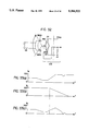
- FIG. 6 is a timing diagram which illustrates the procedure for controlling the regenerative braking process.
- driving coils U, V, and W are wound on a stator 37, and a rotor shaft 19 is mounted with a rotor 51 and a magnet rotor 48 for rotation within the central portion of the stator 37.
- Hall-effect devices UH, VH, and WH are arranged around the magnet rotor 48 for determining, in a non-contactual manner, the angular position of the rotor 51.
- Detection signals produced by the Hall-effect devices are fed to an angular position detecting device 46.
- the angular position detecting device 46 determines the angular position of the rotor 51 based on the detection signals and produces an angular position signal which is fed to a commutation/rectification control device 45.
- the commutation/rectification control device includes a running mode commutation control device 45a which operates during the normal running state, a regenerative mode rectification control device 45b which operates during a regenerative state, and a switching circuit 45c for selecting either the running mode commutation control device 45a or the regenerative mode rectification control device 45b.
- the driving coils U, V, and W are connected to a commutating/rectifying device 90.
- This commutating/rectifying device 90 includes a switching unit 90a which includes transistors and diodes in combination and a pre-driving unit 90b.
- the switching unit 90a controls the power supplied from a battery BA to the driving coils U, V, and W.
- This switching unit 90a also acts as a path for feeding the recharging power from the driving coils to the battery BA.
- the switching circuit 45c selects the running mode commutation control device 45a so that the commutation/rectification control device 45 operates properly during the running mode.
- the running mode commutation control device 45a switches the transistors of the switching unit 90a ON and OFF so that the power being supplied from the battery BA to the driving coils U, V, and W is carried out according to a predetermined timing scheme.
- a DC drive motor M is driven in a rotational manner by the power supply thereto from the battery BA such that the electric vehicle is driven.
- a braking detecting device 79 produces a braking detection signal which is fed to the switching circuit 45c.
- the switching circuit 45c selects the regenerative mode rectification control device 45b.
- the regenerative mode rectification control device 45b switches the transistors ON and OFF so that regenerative power is produced by the drive motor M and consumed by the commutating/rectifying device 90 and the driving coils U, V, and W for braking.
- a three phase AC voltage as shown in FIG. 6(a) is produced by the driving coils U, V, and W.
- the regenerative mode rectification control device 45b feeds a pulse signal to the transistors UTr 1 , VTr 1 , and WTr 1 so that these transistors are turned OFF.
- the regenerative mode rectification control device 45b supplies a pulse signal, as shown in FIG. 6(b), to the transistors UTr 2 , VTr 2 , and WTr 2 so as to turn these transistors OFF and ON periodically and simultaneously.
- the magnitude of the regenerative braking force is proportional to the energy consumed by the transistors, diodes, and driving coils while the transistors UTr2, VTr 2 , and WTr 2 are switched ON
- the magnitude of the regenerative braking force is proportional to the pulsewidth of the pulse signal. Accordingly, the pulsewidth is increased when a large braking force is desired, and the pulsewidth is decreased or diminished, as shown in FIG. 6(c), when a small braking force is desired.
- the prior art devices were not able to control the braking force and the recharging energy individually, the prior art devices found it impossible to carry out a control operation, for example, which decreases the recharging energy when the battery is fully charged and increases the recharging energy when the battery is not fully charged notwithstanding the actual priority to be given to the controlling of the braking force.
- the prior art devices place the braking force as the highest priority and thus ignored the controlling of the recharging energy. Consequently, by ignoring the controlling of the recharging energy, either the battery became overcharged by regenerative braking when the battery was already basically overcharged or the battery could not be readily recharged to its full capacity if the battery was not already fully charged prior to the regenerative process.
- one embodiment of the present invention provides a regenerative braking control system for an electric vehicle which is capable of individually controlling the braking force and the recharging energy during a regenerative braking mode.
- FIG. 34 is a block diagram illustrating a portion of an electric system for controlling the driving of the drive motor of an electric vehicle.
- Driving coils U, V, and W are wound on a stator 37 of a drive motor M.
- a rotor 51 and a magnet rotor 48 are supported for rotation in a central portion of the stator 37.
- Hall-effect position sensors UH, VH, and WH determine, in a non-contactual manner, the angular position of the rotor 51. These position sensors provide position detection signals to a controller 10.
- a driver 90 includes a switching circuit 90a which includes transistors and diodes and a pre-driving unit 90b.
- the driver 90 controls power supplied from a battery BA to the driving coils U, V, and W. Moreover, the driver 90 controls the recharging of the battery BA by the energy generated in the driving coils.
- a motor temperature sensor 21 detects the temperature of the drive motor M and produces a temperature signal TM representing the temperature of the drive motor and feeds this temperature signal to the controller 10.
- a throttle opening sensor 22 detects the opening of the throttle and produces a throttle opening signal TH which represents the actual opening of the throttle and feeds this signal to the controller 10.
- the controller 10 determines the rotor position based on the position signals received from the position sensors.
- FIG. 35 illustrates a table showing the detection signals provided by the position sensors and the corresponding angular positions of the rotor. For example, when the Hall-effect position sensors UH, VH, and WH detect an N-pole, an S-pole, and an S-pole, respectively, the rotor is at an angular position as illustrated by number 1 in FIG. 35.
- the controller 10 determines, on the basis of the throttle opening signal TH, whether the vehicle is in a driving mode (the vehicle is being driven by the drive motor) or whether the vehicle is in a braking mode (when the vehicle is being braked). If the vehicle is in the driving mode, the controller 10 produces output signals to be fed to the transistors of the switching unit 90a as illustrated in FIG. 36.
- FIGS. 6(a)-6(c) illustrate timing charts of the control mode for electrical braking.
- three phase voltage as shown in FIG. 6(a) is generated in coils U, V, and W, respectively.
- the transistors UTr 1 , VTr 1 , and WTr 1 are turned OFF.
- a pulse signal as illustrated in FIG. 6(b), is applied to transistors UTr 2 , VTr 2 , and WTr 2 to turn OFF and ON these transistors periodically and simultaneously.
- the electromotive force generated by the coils is consumed as heat by the coils, transistors, and the diodes when the transistors UTr 2 , VTr 2 , and WTr 2 are switched ON. This allows the drive motor M to be braked.
- the braking force is proportional to the energy consumed by the transistors and diodes while the transistors UTr 2 , VTr 2 , and WTr 2 are switched ON, the braking force is proportional to the duty factor of the pulse signal (braking duty factor). Accordingly, the braking duty factor is increased (the pulsewidth is increased) when a high braking force is necessary. Moreover, the braking duty factor is decreased (the pulsewidth is decreased) when a low braking force is necessary.
- the prior art devices which utilize the system described above are also provided with a second controller for turning OFF all of the transistors of the driver 90 to stop the power from being supplied to the drive motor M, thereby preventing adverse effects upon the components of the electrical system when all of the position sensors produce the same position detection signals due to a malfunction or when the control of the power supplied to the drive motor becomes impossible.
- This hindrance of the controlling of the power supplied to the drive motor M may occur due to a malfunction of the throttle opening sensor or when the temperature of the drive motor increases excessively.
- one embodiment of the present invention provides a controller for an electric vehicle which is capable of satisfactorily controlling the electric system of an electric vehicle even if a portion of the electric system for controlling the drive motor of the electric vehicle malfunctions.
- the present invention provides a regenerative braking control system for an electric vehicle which consumes a portion of energy generated by the drive motor for braking and feeds a portion of the energy to a battery for recharging.
- This regenerative braking control system includes a braking period device for establishing a braking period that is started and ended within a half of a period of an AC voltage created in the coils.
- the system also includes a regenerative device for feeding an induced current corresponding to the energy stored in the coils at the end of a braking period to a battery and an energy consuming circuit for consuming the energy generated during the braking period.
- the braking force is proportional to the integral of the AC power consumed during the braking period. Moreover, the energy used to recharge the battery is dependent upon the electromotive force at the end of the braking period. Accordingly, the braking force and the recharging energy can be individually controlled by properly determining the starting time and ending time of the braking period.
- a regenerative braking control system which includes a first braking period device for establishing a first braking period that is started within a half of a period of the AC voltage created in the coils, a second braking period device for establishing a second braking period that is ended within a half of a period of the AC voltage, a regenerative device for feeding the induced current corresponding to the energy stored in the coils at the end of the first braking period to the power supply, and an energy consuming circuit for consuming energy remaining at the end of the first braking period and the energy generated during the second braking period.
- the braking force is proportional to the integral of the AC power consumed during the first and second braking periods.
- the energy used to recharge the battery is dependent upon the electromotive force at the end of the first braking period. Accordingly, the braking force and the charging energy can be controlled individually by controlling the first and second braking periods.
- a further embodiment of the present invention which controls regenerative braking includes a chopping device for chopping the braking period so that the braking period consists of a plurality of intermittent short braking periods.
- the recharging energy can be increased because a current is being induced at the end of every intermittent short braking period.
- a controller which includes a monitor for monitoring the electric system to determine whether the electric system is functioning normally and an electrical braking device for electrically braking the drive motor when the monitor determines that the electric system or a portion of the electric system is malfunctioning.
- the controller actuates the electric braking device upon the detection of the malfunction in the electric system. Accordingly, the vehicle can be decelerated in a satisfactory manner even if a portion of the electric system malfunctions while the vehicle is running.
- Another embodiment of the present invention is a controller which includes a monitor for monitoring if the electric system is functioning normally and a correcting circuit for gradually decreasing the voltage used to control speed when a malfunction is detected by the monitor. This decreased voltage is applied to the drive motor when a malfunction is detected to control the motor's speed.
- the malfunction of a portion of the electric system is detected by the monitor.
- the controller applies a voltage which is gradually decreasing. Accordingly, the power being supplied to the drive motor can be decreased without significantly deteriorating the controllability of the vehicle after a malfunction is detected in a portion of the electric system.
- FIG. 1 is a general view of an electric motorcycle incorporating the present invention
- FIG. 2 is a sectional view of a power unit utilized by the present invention
- FIG. 3 is another sectional view of a power unit utilized by the present invention.
- FIG. 4 is a third sectional view of a power unit utilized by the present invention.
- FIG. 5 is a block diagram illustrating a motor control system for an electric vehicle
- FIGS. 6(a)-6(c) are timing diagrams illustrating a conventional control method for regenerative braking
- FIG. 7 is a graphical representation of the concepts of the present invention.
- FIG. 8 is another graphical representation of the concepts of the present invention.
- FIG. 9 is a third graphical representation of the concepts of the present invention.
- FIGS. 10(a)-10(d) are diagrams illustrating control modes according to the present invention.
- FIG. 11 is a circuit diagram illustrating another motor control system according to the present invention.
- FIG. 12 is a circuit diagram illustrating another motor control system according to the present invention.
- FIG. 13 is a timing diagram illustrating the operation of the motor control systems illustrated in FIGS. 11 and 12;
- FIG. 14 is a graph showing a relationship between decelerating torque and motor speed
- FIG. 15 is a graph showing a relationship between motor speed and an angle( ⁇ 1 + ⁇ 2 );
- FIG. 16 is a graph showing a relationship between motor speed and an angle ⁇ 1 ;
- FIG. 17 is a flow chart illustrating a regenerative braking control routine according to the present invention.
- FIG. 18 is a flow chart illustrating an interrupt sub-routine executed during a regenerative braking control routine according to the present invention
- FIG. 19 is a flow chart illustrating an interrupt sub-routine executed during a regenerative braking control routine according to the present invention.
- FIG. 20 is a diagram illustrating a method for controlling angle ⁇ 1 ;
- FIGS. 21(a)-21(d) are diagrams illustrating control modes of other embodiments of the present invention.
- FIG. 22 is a block diagram of a motor control system according to the present invention.
- FIG. 23 illustrates an example of a duty factor map
- FIG. 24 is a diagram illustrating a method for producing a duty factor map
- FIGS. 25(a) and 25(b) are diagrams illustrating another method for producing a duty factor map
- FIG. 26 is a diagram illustrating a third method for producing a duty factor map
- FIG. 27 is a diagram illustrating a fourth method for producing a duty factor map
- FIG. 28 is a timing diagram illustrating a chopping control method according to another embodiment of the present invention.
- FIG. 29 is a block diagram of a third embodiment of the present invention.
- FIG. 30 is a block diagram of the driving signal output device illustrated in FIG. 29;
- FIG. 31 is a flow chart illustrating the operations of the driving signal output device of FIG. 29;
- FIG. 32 illustrates a throttle opening sensor
- FIGS. 33(a)-33(c) are charts illustrating other embodiments of the present invention.
- FIG. 34 is a block diagram of an electric control system employed in an electric vehicle
- FIG. 35 is a table showing a relationship between signals provided by angular position sensors and an angular position of a rotor
- FIG. 36 is a table illustrating the control of the drive motor according to an angular position of a rotor
- FIG. 37 is a graph illustrating a relationship between a driving duty factor and a throttle opening signal.
- FIG. 38 is a graph illustrating a relationship between a braking duty factor and a throttle opening signal.
- FIG. 1 is an illustration generally showing an electric motorcycle incorporating the present invention.
- the electric motorcycle X has a mainframe F consisting of a front frame F1, a middle frame F2, and a rear frame F3. Each frame is formed of steel pipes.
- Main frame F is covered with a leg shelf B1, a step floor B2, a rear cover B3, and an undercover B4.
- a steering device 2 is attached to the upper end of a head pipe 1 and fixed to the front frame F1.
- a front fork 4 for suspending a front wheel WF by a front shock absorber 3 is joined for turning the lower end of the head pipe 1.
- a swing power unit P has a front end pivotally joined to the rear end of the metal frame F2 by a pivot 5.
- a rear end of the swing power unit P supports a rear wheel WR by a rear axle.
- the power unit P swings vertically on the pivot 5.
- a rear shock absorber 6 has a lower end joined to the upper surface of the rear portion of the power unit P and an upper end joined to the rear frame F3.
- a stand 7 is connected to the middle frame F2 so as to cover the front lower surface of the power unit to serve as a protective member which protects the drive unit of the power unit P.
- a storage box 9 for containing a helmet and other items is provided between the power unit P and a seat 8.
- the storage box 9 is formed of a material capable of magnetic shielding, such as a conductive resin, to protect the contents from the magnetism of the drive motor M.
- a battery box 10 contains a battery for supplying power to the drive motor and is supported on the middle frame F2.
- a controller 11 for controlling the drive motor M and a recharger 12 for recharging the battery are provided in front of the head pipe 1.
- the power unit P has a front transmission case 13.
- the pivot 5 extends laterally through the transmission case 13.
- the drive motor M is placed in front of the transmission case 13.
- a reduction gear 14 is placed in the rear portion of the transmission case 13.
- the drive motor M and the reduction gear 14 are interlocked by a belt-type continuously variable speed transmission 15.
- the transmission case 13 is divided into a left hand transmission chamber 13b for containing the belt-type continuously variable speed transmission 15 and a right hand motor chamber 13c for containing the drive motor M.
- the transmission case is divided by a partition wall 13a.
- a motor housing 16 housing the drive motor M is placed in the motor chamber 13c.
- a driver housing 13d forms a portion of the transmission case 13 and contains a driver 25. This driver housing 13d is joined to the right end surface of the motor housing 16 and is fastened to the motor housing by bolts 18.
- the rotor shaft 19 of the drive motor M is supported by a ball bearing 20 provided in the motor housing 16 and is further supported by a ball bearing 21 provided on the inner wall of the transmission case 13.
- a cooling fan 22 is mounted on the right hand of the rotor shaft 19 within the motor housing 16.
- a flexible duct 23 for introducing cooling air into the motor chamber 13c has a lower end joined to the upper wall of the transmission case 13 at the position between the drive motor M and the belt-type continuously variable speed transmission 15. Also,the flexible duct 23 has an upper end opening into the storage box 9.
- the driver 25 having a substantially hexagonal shape is disposed coaxially with the rotor shaft 19 and the driver housing 13(d).
- the driver 25 is also fastened to the motor housing 16 with bolts 24.
- a plurality of cooling fans 26 project from the inner surfaces of the sides of the driver 25.
- FETs Field Effect Transistors 27
- a capacitor 28 having a large capacitance is firmly fitted in the central space of the driver.
- the right hand open end at the motor housing 16 is covered with a cover provided with a discharge opening 29a which includes louvers.
- Drive motor M is a DC brushless motor having a rotor 33 formed by arranging permanent magnets 32 on an outer circumference of a core 31 fixedly mounted on the rotor shaft 19.
- Stator 37 is formed by winding coil 36 on a core 35 disposed within and fastened to the motor housing 16 with bolts 34.
- the angular position sensor 40 detects the angular position of the rotor 33.
- a magnet rotor 48 is fixedly mounted on the rotor shaft 19.
- Three Hall-effect devices 39(UH, VH, and WH) are disposed opposite to the outer circumference of a magnet rotor 48.
- Cooling air is introduced through the storage box 9 and the duct 23 into the motor chamber 13c by the cooling fan 22. This cooling air cools the drive motor M and flows through hole 16a formed in the motor housing 16 and into the driver housing 13d. Moreover, the cooling air cools the FETS 27 and the capacitor 28 before flowing outside through the discharge opening 29a of the cover 29.
- the belt-type continuously variable speed transmission 15 has a driving pulley 61 mounted on a portion of the rotor shaft 19 projecting into the transmission case 13.
- a driven pulley 63 is mounted on the input shaft 62 of the reduction gear 14 supported on the rear portion of the transmission case 13.
- An endless belt 64 is extended between the pulleys 61 and 63.
- the driving pulley 61 consists of a fixed pulley element 61a connected to the rotor shaft 19 and a moveable pulley element 61b actually slidable mounted on the rotor shaft 19. Centrifugal weights 66 are provided to move radially between the moveable pulley element 61b and a ramp plate 65 fixed to the rotor shaft 15.
- the driven pulley 63 consists of a fixed pulley element 63a placed on a collar 68.
- a needle bearing 67 on the input shaft 62 of the reduction gear 14 is supported for rotation relative to the input shaft 62 of the reduction gear 14.
- a moveable pulley element 63b is mounted on the collar 68 for axial movement thereon.
- a driving force is transmitted from the rotor shaft 19 to the driven pulley 63 through an automatic centrifugal clutch 69 and the input shaft 62.
- the driving force from the input shaft 62 of the reduction gear 14 is transmitted through another automatic centrifugal clutch 70 to the driven pulley 63.
- the input shaft 62 of the reduction gear 14 is supported by a pair of ball bearings 71 and 72 provided on the transmission case 13.
- Intermediate shaft 76 is supported on the transmission case 13 between the input shaft 62 and a rear axle 75 supported by a pair of ball bearings 73 and 74.
- these ball bearings 73 and 74 support the rear wheel WR.
- the rotation of a driving gear 77 mounted on the input shaft 62 is transmitted by two intermediate gears 78 and 79 mounted on the intermediate shaft 76 to a driven gear 80 fixed to the rear axle 75.
- the automatic centrifugal clutch 69 remains disengaged, and hence, the driving force of the drive motor is not transmitted to the rear wheel WR.
- the centrifugal weights move radially outward along the ramp plate 65 fixed to the rotor shaft 19 to shift the moveable pulley element 61b of the driving pulley 61 toward the fixed pulley element 61a. Consequently, the effective radius of the driving pulley 61 increases while the moveable pulley element 63b of the driven pulley 63 is shifted away from the fixed pulley element 63a by the endless belt 64, thereby decreasing the effective radius of the driven pulley 63.
- the operative ratio of the belt-type continuously variable speed transmission 15 is decreased to increase the rotating speed of the collar 68 which rotates together with the driven pulley 63.
- the automatic centrifugal clutch 69 is engaged to transmit the driving force of the drive motor M to the input shaft 62 of the reduction gear 14, and consequently, the rear wheel WR is driven.
- Clean air prevailing in the storage box 9 is introduced through the duct 23 into the motor chamber 13c of the transmission case 13 by the cooling fan 22 which rotates together with the rotor motor shaft 19 of the drive motor M.
- the cooling air removes heat generated by the coils 36 of the drive motor M.
- This cooling air flows through the hole 16a formed in the motor housing 16 and into the driver housing 13d.
- the cooling air flows along the outer circumference of the driver 25 and through spaces between the cooling fans 26 to cool the FETS 27 and the capacitor 28.
- the cooling air flows outside through the discharge opening 29a of the cover 29.
- the duct 23 which guides the cooling air into the transmission case 13 is joined to the upper wall of the transmission case 13 at the position between the drive motor M and the belt-type continuously variable speed transmission 15, the duct does not protrude laterally from the transmission case 13 to increase the overall width of the transmission case.
- the dead space between the drive motor M and the belt-type continuously variable speed transmission 15 can effectively be utilized.
- duty factor of the pulse signal for controlling the power supplied to the drive motor M will be referred to simply as duty factor.
- FIG. 22 is a functional block diagram of a motor driving system which illustrates only the functions necessary for driving the drive motor M by the power supplied from the battery.
- a speed detecting device 101 detects the motor speed Ne, i.e., the rotating speed of the rotor shaft 19 of the drive motor M.
- a throttle opening detecting device 102 detects a throttle opening ⁇ th .
- a battery voltage detecting device 103 detects the battery voltage.
- a duty factor map storage device 106 stores data D(x,y) which represents the duty factors as a function of motor speed Ne and a throttle opening ⁇ th , as shown in FIG. 23.
- a duty factor calculating circuit 104 chooses duty factor data D(x,y) which corresponds to the detected motor speed Ne and the detected throttle opening ⁇ th from the duty factor map storage device 106. If any duty factor data D(x,y) which correspond to the detected motor speed Ne and the detected throttle opening TH is not found in the duty factor map storage device, optimal duty factor data D(x,y) is calculated by interpolation.
- a voltage correcting device 105 corrects a duty factor so that a desired motor output is obtained regardless of the battery voltage.
- the output of the drive motor is controlled by varying the duty factor of the pulse signal, the output of the drive motor decreases when the battery voltage drops below a standard voltage even if the duty factor is held constant. Accordingly, the present invention regulates the duty factor so that the duty factor is increased when the battery voltage i s low and the duty factor decreases when the battery voltage is high so as to maintain the desired output of the drive motor regardless of the battery voltage.
- the present invention corrects the duty factor by multiplying the calculated duty factor by a reference voltage and dividing the product of this multiplication by the battery voltage. This calculation gives the present invention the corrected duty factor. By utilizing the corrected duty factor, the desired output of the motor can be obtained regardless of the variation in the battery voltage.
- the present invention determines the duty factor as a function of the motor speed Ne and the throttle opening ⁇ th , the following various control operations are able to be accomplished.
- FIG. 24 shows an example of the duty factor data map stored in the duty factor map storage device 106.
- the present invention chooses a small duty factor regardless of the throttle opening ⁇ th at the starting of the drive motor or while the motor speed is low. Although, normally, a high current corresponding to a locking current tends to flow through the drive motor due to the inertial mass of the rotor when starting the drive motor, the present invention chooses a small duty factor during the starting of the drive motor and during Low speed operations to inhibit a high current from flowing through the drive motor. Selection of the duty factor for maintaining the efficiency of the drive motor on a sufficiently high level will be described below.
- Graph(a) of FIG. 25 illustrates the general relationship between the motor speed Ne, motor output P, and efficiency ⁇ . Since the electric vehicle requires a large torque when starting the electric vehicle, a characteristic of the motor output P, as shown in graph(a) of FIG. 25, has been used. In other words, the higher the torque is and the lower the motor speed Ne is, a sufficiently high acceleration can be realized by utilizing this characteristic. However, if this characteristic is utilized during the starting of the electric vehicle, the efficiency ⁇ of the drive motor greatly deteriorated.
- the present invention determines the relationship between the motor speed Ne (when the motor efficiency ⁇ is 70%) and the throttle opening ⁇ th is at a maximum and the duty factor as shown in graph(b) of FIG. 25. This relationship is stored in the duty factor map storage device 106 wherein the present invention chooses a duty factor corresponding to the motor speed Ne so that the drive motor operates at an efficiency not lower than 70%.
- a duty factor corresponding to a throttle opening smaller than the maximum throttle opening is smaller than a duty factor corresponding to the maximum throttle opening. Since the duty factor is regulated so that the area under a curve representing the conditions for maintaining a 70% efficiency is satisfied, the efficiency is not lower than 70% for any throttle opening lower than the maximum throttle opening if the relationship for the maximum throttle opening is determined.
- FIG. 26 shows the variation of the motor output P with the motor speed Ne for the duty factor K and running resistance R at a medium throttle opening.
- the present invention employs a duty factor map so that the relationship between the motor output P and the motor speed Ne at a medium throttle opening is similar to curve 2. This enables the acceleration (curve 2 - running resistance) to be high in the initial stage of acceleration and enables the acceleration to decrease with an increase in running speed.
- the increment of the throttle opening necessary for increasing the engine speed to a value sufficient for the clutch to transmit power is not very large.
- the disparity between the operation of throttle and the response of the vehicle is not very significant. If the drive motor is kept running for idling even while the throttle is fully closed, the unsatisfactory performance when starting an electric vehicle may be eliminated.
- the operation of the drive motor for idling increases power consumption and thus reduces the distance that the vehicle can travel without recharging the battery.
- the present invention controls a duty factor K so that the duty factor K increases instantaneously to a threshold K(S) slightly smaller than the lower limit K(L) upon the increase of the throttle opening ⁇ th corresponding to a starting motor speed as indicated by continuous line 2 in FIG. 27.
- the range d2 for idling operations of the drive motor a time interval from the start of the drive motor to the start of the electric vehicle, is curtailed to eliminate any unsatisfactory operations.
- FIGS. 7, 8, and 9 are graphs illustrating the basic concepts of the present invention.
- one period of an AC electromotive force produced in coil U corresponds to an electrical angle range of 0° to 360° and a mechanical angle range of 0° to 180°
- an ON period of the transistors to be started at an electrical angle 0° within the electrical angle range of 0° to 90° is represented by angle ⁇ 1
- an ON period of the transistors to be ended within an electrical angle 180° of the electrical angle range of 90° to 180° is represented by an angle ⁇ 2 .
- a recharging current I is supplied to the battery BA wherein this recharging current was induced in the coils when the transistors are turned OFF.
- the magnitude of the recharging current I is proportional to the electromotive force of the coil immediately before the transistors are switched OFF. Accordingly, it is desirable that the angle ⁇ 1 be nearly equal to 90° as shown in FIG. 7 when it is desirable to have the recharging current I at its maximum.
- the regenerative torque, the braking force is proportional to the amount of energy consumed by the transistors, diodes, and coils when the transistors are in the ON state. This amount of energy is equal to the integral S 1 of the electromotive force induced in the coils when the transistors are in the ON state. Accordingly, it is desirable to increase the angle ⁇ 1 , as shown in FIG. 7, when it is desired to have maximum braking force.
- the present invention employs a second angle ⁇ 2 for individually controlling the recharging current and the braking force.
- the transistors are switched OFF always at an electrical angle of 180° within an electrical angle range of 90° to 180°, the induced current is zero, and hence.
- the recharging current is always zero.
- the braking force is dependent upon the integral S 2 of the electromotive force as illustrated in FIG. 9.
- the present invention controls the angles of ⁇ 1 and ⁇ 2 individually for each coil to control the recharging current and the braking force individually.
- FIGS. 10(a)-10(d) illustrate the control diagrams for individually controlling the recharging current and the braking force by individually controlling the angles ⁇ 1 and ⁇ 2 for each coil.
- both angles ⁇ 1 and ⁇ 2 are increased, both the recharging current and the braking force are increased.
- angle ⁇ 1 is increased and angle ⁇ 2 is decreased, the recharging current is increased and the braking force is decreased.
- the angle ⁇ 1 is decreased and the angle ⁇ 2 is increased, the recharging current is decreased and the braking force in increased.
- both angles ⁇ 1 and ⁇ 2 are decreased, both the recharging current and the braking force are decreased.
- FIGS. 11 and 12 are circuit diagrams illustrating the principle portion of the motor control system described with reference to FIG. 5.
- FIG. 13 is a timing diagram of the operations to be carried out by the motor control system.
- UH, VH, and WH are respective output signals of the Hall-effect devices UH, VH, and WH.
- the DC motor has driving coils U, V, and W in a three phase construction, circuits relating mainly to coil U will be described below because each phase is constructed the same.
- the transistors UTr 1 VTr 1 and WTr 1 are turned OFF and only the transistor UTr 2 is switched ON. Therefore, a closed circuit consisting of coil U, transistor UTr 2 , diode VD 2 and coil V and a closed circuit consisting of coil W, transistor WTr 2 , diode VD 2 and coil D are formed as shown in FIG. 11. Accordingly, the electromotive force produced in each coil is converted into heat by the coils, transistors, and diodes, thereby enabling braking.
- the decelerating torque in the full regenerative braking mode increases according to the motor speed Ne until the motor speed Ne reaches its peak Ne 1 , as indicated by the continuous line in FIG. 14. Moreover, the decelerating torque decreases gradually with the increase of the motor speed Ne after the motor speed Ne has exceeded speed Ne 1 . However, it is desirable that the decelerating torque increases continuously according to the motor speed Ne so that the rate of the motor speed decreases gradually with the increase of the motor speed Ne as indicated by a dotted line in FIG. 14.
- angle ( ⁇ 1 + ⁇ 2 ) is decreased with the increase of the motor speed Ne until the motor speed Ne reaches the motor speed Ne 1 as illustrated in FIG. 15.
- the angle ( ⁇ 1 + ⁇ 2 ) is increased gradually after the motor speed Ne has exceeded speed Ne 1 as also illustrated in FIG. 15.
- This is a function of f(Ne) which characteristic is illustrated by the dotted line in FIG. 14.
- An ideal decelerating torque characteristic as a function of the motor speed Ne can be attained by such control of the angles ⁇ 1 and ⁇ 2 so that the controllability of the motor speed is improved.
- Angle ⁇ 1 is decreased gradually with the increase of the motor speed Ne as a function g(Ne) as shown in FIG. 16 so that the voltage of the battery BA is held constant during regenerative braking.
- FIG. 17 is a flow chart showing the control of regenerative braking operations.
- FIGS. 18 and 19 are flow charts illustrating interrupt sub-routines to be executed at predetermined times during the control cycle.
- the motor control system starts the control operations when connected to a power supply.
- a throttle opening ⁇ th is detected, and the driving duty factor is determined on the basis of a throttle opening and the motor speed Ne in step S11.
- Step S12 it is determined if the driving duty factor is greater than zero.
- Step S17 is executed if the response in step S12 is affirmative and it is determined that the electric motorcycle is running.
- Step S13 is executed for regenerative braking if the response in step S12 is negative.
- step S17 the transistors UTr 1 , VTr 1 , WTr 1 , UTr 2 , VTr 2 , and WTr 2 , are switched OFF and ON properly to drive the drive motor.
- the routine returns to step S10.
- step S13 the transistors UTr 1 , VTr 1 , and WTr 1 are switched OFF.
- step S14 the battery voltage is detected to determine if the battery BA is fully charged.
- Step S15 is executed if the battery BA is fully charged.
- Step S16 is executed when the battery BA is not fully charged.
- step S15 the angle ⁇ 1 is set to zero and angle ⁇ 2 is set at an angle determined by the function f(Ne) as shown in FIG. 15.
- step S16 the angle ⁇ 1 is set at an angle determined by the function g(Ne) as shown in FIG. 16. Since the braking force is effective during a period corresponding to angle ⁇ 1 , angle ⁇ 2 is set at an angle determined by subtracting the angle ⁇ 1 from the angle determined by the function f(Ne) as illustrated in FIG. 15.
- the interruption subroutine of FIG. 18 is executed at step S20 to determine the motor speed Ne and the transistor UTr 2 is switched OFF at step S21.
- a time T1 necessary for setting the angle ⁇ 1 as determined in step S14 or S15 of the main routing is calculated.
- a time T2 necessary for setting the angle ⁇ 2 is also calculated at step S23.
- time T1 corresponds to the angle ⁇ 1
- time T2 corresponds to a time from the detection of the leading edge of the output signal of the Hall-effect device UH to the start of the period corresponding to angle ⁇ 2 .
- step S30 the transistor UTr 2 is switched ON to start a period corresponding to angle ⁇ 1 .
- the measuring of time T1 is started at step S31, and the measuring of time T2 is started at step S32.
- the transistor UTr 2 Upon the detection of the termination of the period corresponding to angle ⁇ 1 , the transistor UTr 2 is turned OFF. Upon the detection of the termination of the period corresponding to angle ⁇ 2 , the transistor UTr 2 is switched ON again to start the period corresponding to angle ⁇ 2 .
- angle ⁇ 1 may be a function of the motor speed Ne and the battery voltage.
- the period corresponding to the angle ⁇ 1 is ended in the initial half (before an electrical angle 90°) of a half of a period of the AC voltage induced in the current coil.
- the periods, respectively, corresponding to angles ⁇ 1 or ⁇ 2 may be ended or started at appropriate angles within the range of electric angles 0° to 180°.
- the electric angle ⁇ 1 or ⁇ 2 may be substituted by a single angle ⁇ 3 which represents a period to be started within a half of a period (a period corresponding to the range of the electrical angle of 0° to 180°) of the AC voltage induced in the coil.
- the time for starting the period corresponding to angle ⁇ 3 and the time for ending the period corresponding to angle ⁇ 3 may be determined properly so that individual control of the braking force and recharging current can be realized.
- FIGS. 21(a)-21(d) illustrate control modes for individually controlling braking force and recharging current by properly setting the angle ⁇ 3 .
- the period corresponding to angle ⁇ 3 is started at an electrical angle nearly equal to an electrical angle of 90° and is ended at an electrical angle nearly equal to an electrical angle of 180° to obtain a high braking force and a low recharging current (FIG. 21(a)).
- the period corresponding to angle ⁇ 3 is started at an electrical angle nearly equal to an electrical angle of 0° and is ended at an electrical angle nearly equal to an electrical angle of 90° to obtain a high braking force and a high recharging current (FIG. 21(b)).
- the period corresponding to angle ⁇ 3 is ended at an electrical angle nearly equal to an electrical angle of 90° and is started just before the electrical angle at which the period is ended to obtain a low braking force and a high recharging current (FIG. 21(c)).
- the period corresponding to angle ⁇ 3 is ended at an electrical angle nearly equal to an electrical angle of 180° and is started just before the electrical angle at which the period is ended to obtain a low braking force and a low recharging current (FIG. 21(d)).
- This embodiment of the present invention controls the electrical angle at which the period corresponding to the angle ⁇ 3 is started to control braking force and controls the electrical angle at which the period corresponding to the angle ⁇ 3 is ended to control recharging current. This enables individual determination of the braking force and recharging current.
- Angle ⁇ 3 is decreased with the increase of the motor speed Ne until the motor speed Ne reaches the predetermined speed Ne 1 and is increased gradually after the motor speed Ne has exceeded the speed Ne 1 as mentioned above.
- the transistors UTr 2 , VTr 2 , and WTr 2 are switched ON during the braking periods, respectively, corresponding to angles ⁇ 1 , ⁇ 2 , and ⁇ 3 .
- the transistors are controlled in such a manner, the recharging current used to recharge the battery BA is induced only once in the half of a period of the AC voltage at the end of the period corresponding to angle ⁇ 1 , or ⁇ 3 , and hence, it is impossible to obtain a large recharging current.
- the transistors UTr 2 , VTr 2 , and WTr2 are controlled using a chopping mode during the period corresponding to angle ⁇ 1 , ⁇ 2 , or ⁇ 3 so that the braking period consists of a plurality of intermittent short braking periods.
- the frequency of inducing a current is increased to obtain a higher recharging current.
- FIG. 28 is a timing diagram showing the chopping control of the transistor UTr 2 , VTr 2 , and WTr 2 , corresponding to angle ⁇ 1 .
- This embodiment increases the frequency of the inducing current and the braking period corresponding to angle ⁇ 1 , thereby increasing the recharging current substantially by chopping the control of the transistors UTr 2 , VTr 2 , and WTr 2 corresponding to angle ⁇ 1 .
- FIG. 29 is a block diagram showing the functions of a portion of a controller in another preferred embodiment of the present invention corresponding to the controller 10 as previously described with reference to FIG. 34.
- An angular position detecting device 101 determines the angular position of the rotor on the basis of the angular position detection signals provided by angular position sensors and generates an angular position signal for a driving signal output device 105. If the angular position detection signals provided by the angular position sensors are all the same, the angular position detecting device 101 produces an angular position coincidence signal and feeds this coincidence signal to a monitor 102.
- a throttle opening signal TH representing the opening of a throttle being outside a reference range
- a temperature signal TM representing a temperature of the drive motor being higher than an upper limit temperature
- a signal representing the output voltage of a battery being lower than a lower limit is fed to the monitor 102
- the monitor 102 produces a monitor signal for the driving signal output device 105 and feeds the input throttle opening signal TH to a driving duty factor determining device 103 and a braking duty factor determining device 104.
- FIG. 32 illustrates a throttle opening sensor.
- a potentiometer 143 is connected operatively to a throttle grip 141. The resistance of the potentiometer varies according to the angular position of the throttle grip 41. The output voltage of the potentiometer 143 is fed as the throttle opening signal TH to the driving signal output device 105.
- the angular turning range of the throttle grip 41 is defined by stoppers 142a and 142b so that the output voltage of the potentiometer 143 is in a range of, for example, 0.5 volts to 4.5 volts. Accordingly, if a voltage outside the range of the potentiometer 143 is detected by the driving signal output device 105, it is determined that the throttle opening sensor is not functioning normally.
- the driving duty factor determining device 103 and the brake duty factor determining device 104 determines the driving duty factor and the brake duty factor, respectively, on the basis of the throttle opening signal TH as shown in FIGS. 37 and 38.
- the driving signal output device 105 switches ON and OFF the transistors of a driver 90 according to the angular position of the rotor, the driving duty factor, the braking duty factor, and the monitor signal.
- FIG. 30 is a block diagram of the driving signal output device 105
- FIG. 31 is a flow chart illustrating the operations of the driving signal output device 105.
- step S110 a driving duty factor, a braking duty factor, and a monitor signal are fed to a driving/braking/monitoring determining device 105b.
- step S111 it is determined, on the basis of the monitor signal, if an electric control system for controlling the drive motor is functioning normally. If the electric control system is functioning normally, it is determined at step S112 if the driving duty factor is zero.
- the driving duty factor is fed as an output duty factor from a pulse signal generating device, 105c, to AND gates 105d in step S113.
- a driving mode signal i.e., a mode signal indicating a driving mode, is fed to an ON/OFF decision device 105a.
- Step S114 the braking duty factor is fed as an output duty factor to the pulse signal generating device 105c.
- the pulse signal generating device 105c applies a pulse signal having the braking duty factor to AND gates 105d.
- step S117 a braking mode signal, a mode signal indicating a braking mode, is fed to the ON/OFF decision device 105a.
- the mode signal is a driving mode signal
- a driving signal described with respect to FIG. 36 is provided at step S120. Consequently, the AND gates 105d provide a pulse signal having the predetermined duty factor to control the ON/OFF of the transistors.
- FIGS. 33(a)-33(c) are diagrams illustrating the controller of this embodiment of the present invention in which FIG. 33(a) illustrates the variation of the throttle opening signal TH representing the opening of the throttle with time, FIG. 33(b) illustrates the variation of the correction factor K for multiplying the throttle opening signal TH with time, and FIG. 33(c) illustrates a variation of a corrected output obtained by multiplying the throttle opening signal TH by the correction coefficient with time.
- the throttle opening signal TH is multiplied by the correction factor K which decreases gradually from 100% after the detection of the malfunction of a portion of the electric control system.
- the power supplied to the drive motor is controlled on the basis of the corrected throttle opening signal. Although the power supplied to the drive motor is decreased gradually after the detection of the malfunction of the portion of the electric control system, the controllability is not significantly effected because control of the drive motor according to the operations of the throttle is possible.
- the electric vehicle can satisfactorily be decelerated by electrically braking the electric vehicle in the braking mode as described above even if a portion of the electric control system malfunctions while the electric vehicle is running.
- the preferential control of the recharging current through the control of time at which a period corresponding to ⁇ 1 is to be ended and the control of time at which a period corresponding to the angle ⁇ 2 is to be started so that inefficient braking force obtained during the period corresponding to the angle is supplemented, thereby enabling the individual determination of the braking force and individually controlling the recharging energy during the regenerated braking mode.
- the control of the recharging current through the control of time at which a period corresponding to the angle ⁇ 3 is to be ended and the control of the braking force through the control of the time at which the period corresponding to angle ⁇ 3 is to be started enables individual control of the braking force and recharging energy during the regenerative braking mode.
- the chopping control of the transistors during the periods, respectively, corresponding to angles ⁇ 1, ⁇ 2 , and ⁇ 3 and the control of the braking force through the control of the starting time, increases the frequency at which the induced current is produced, thereby enhancing the recharging current.
- the controllability is not significantly hindered and appropriate measures can be taken when the electric control system malfunctions because a throttle opening signal is multiplied by a correction coefficient which gradually decreases.
- the power supplied to the drive motor is controlled according to the corrected throttle opening signal after the malfunction of the electric control system.
Landscapes
- Engineering & Computer Science (AREA)
- Power Engineering (AREA)
- Transportation (AREA)
- Mechanical Engineering (AREA)
- Life Sciences & Earth Sciences (AREA)
- Sustainable Development (AREA)
- Sustainable Energy (AREA)
- Electric Propulsion And Braking For Vehicles (AREA)
Priority Applications (1)
| Application Number | Priority Date | Filing Date | Title |
|---|---|---|---|
| US08/592,601 US5644202A (en) | 1991-04-09 | 1996-01-26 | Braking control system for an electric vehicle |
Applications Claiming Priority (6)
| Application Number | Priority Date | Filing Date | Title |
|---|---|---|---|
| JP10332491 | 1991-04-09 | ||
| JP3-103324 | 1991-04-09 | ||
| JP10509891A JP3160308B2 (ja) | 1991-04-11 | 1991-04-11 | 電動式車両の制御装置 |
| JP3-105098 | 1991-04-11 | ||
| JP29956291A JP3155313B2 (ja) | 1991-04-09 | 1991-10-21 | 電動式車両の回生制動制御装置 |
| JP3-299562 | 1991-10-21 |
Related Child Applications (1)
| Application Number | Title | Priority Date | Filing Date |
|---|---|---|---|
| US29219394A Division | 1991-04-09 | 1994-08-18 |
Publications (1)
| Publication Number | Publication Date |
|---|---|
| US5384522A true US5384522A (en) | 1995-01-24 |
Family
ID=27309956
Family Applications (2)
| Application Number | Title | Priority Date | Filing Date |
|---|---|---|---|
| US07/866,339 Expired - Lifetime US5384522A (en) | 1991-04-09 | 1992-04-09 | Braking control system for an electric vehicle |
| US08/592,601 Expired - Fee Related US5644202A (en) | 1991-04-09 | 1996-01-26 | Braking control system for an electric vehicle |
Family Applications After (1)
| Application Number | Title | Priority Date | Filing Date |
|---|---|---|---|
| US08/592,601 Expired - Fee Related US5644202A (en) | 1991-04-09 | 1996-01-26 | Braking control system for an electric vehicle |
Country Status (3)
| Country | Link |
|---|---|
| US (2) | US5384522A (de) |
| EP (3) | EP0663312B1 (de) |
| DE (3) | DE69221760T2 (de) |
Cited By (19)
| Publication number | Priority date | Publication date | Assignee | Title |
|---|---|---|---|---|
| US5583406A (en) * | 1993-11-16 | 1996-12-10 | Hitachi, Ltd. | Control method and system for regeneration braking of an electric vehicle |
| US5600215A (en) * | 1994-07-07 | 1997-02-04 | Hitachi, Ltd. | Controller for electric vehicle |
| US5652825A (en) * | 1993-10-25 | 1997-07-29 | Papst-Motoren Gmbh & Co. Kg | Power supply for low-voltage DC motor |
| US5726541A (en) * | 1992-04-28 | 1998-03-10 | Dynamic Controls Limited | Failure detection and communication system for electrically driven vehicles |
| US5757161A (en) * | 1994-12-01 | 1998-05-26 | Matsushita Electric Industrial Co., Ltd. | Apparatus and method for limiting the speed of an electric motor |
| US6040561A (en) * | 1999-06-30 | 2000-03-21 | General Motors Corporation | High voltage bus and auxiliary heater control system for an electric or hybrid vehicle |
| US6072292A (en) * | 1996-09-17 | 2000-06-06 | Yamaha Hatsudoki Kabushiki Kaisha | Control for electric motor operated vehicle |
| US6317673B1 (en) * | 1999-06-11 | 2001-11-13 | Chung-Hsien Lin | Electrical apparatus for assisting mechanical braking in a motor cycle |
| US6424798B1 (en) * | 1999-05-31 | 2002-07-23 | Denso Corporation | Device for controlling sensorless brushless-DC-motor |
| US6452349B1 (en) | 1998-11-09 | 2002-09-17 | Papst-Motoren Gmbh & Co. Kg | Electronically commutated motor |
| US6724165B2 (en) | 2002-03-11 | 2004-04-20 | Vectrix Corporation | Regenerative braking system for an electric vehicle |
| US20090160371A1 (en) * | 2007-12-25 | 2009-06-25 | Panasonic Electric Works Co., Ltd. | Electric power tool |
| US20120217098A1 (en) * | 2009-11-02 | 2012-08-30 | Kone Corporation | Braking apparatus, electric drive, and elevator system |
| US20150091480A1 (en) * | 2013-09-28 | 2015-04-02 | Andreas Stihl Ag & Co. Kg | Method for braking an electric drive motor |
| US20150298676A1 (en) * | 2012-11-24 | 2015-10-22 | Toyota Jidosha Kabushiki Kaisha | Vehicle state determination device, vehicle state determination method, and driving operation diagnosis device |
| US20180183363A1 (en) * | 2016-12-28 | 2018-06-28 | Mabuchi Motor Co., Ltd. | Control device and method for controlling the same |
| CN109552061A (zh) * | 2017-09-25 | 2019-04-02 | 株式会社斯巴鲁 | 车辆的控制系统及车辆的控制方法 |
| WO2019075193A1 (en) * | 2017-10-11 | 2019-04-18 | Velocity Magnetics, Inc. | USE OF SYNCHRONOUS LINEAR MOTORS TO DELAY LINEAR MOVEMENT AND TRANSPORT SYSTEMS |
| US11866117B2 (en) | 2019-01-16 | 2024-01-09 | Livewire Ev, Llc | Motorcycle with virtual braking and virtual clutch |
Families Citing this family (61)
| Publication number | Priority date | Publication date | Assignee | Title |
|---|---|---|---|---|
| US6779621B2 (en) | 1993-02-24 | 2004-08-24 | Deka Products Limited Partnership | Riderless stabilization of a balancing transporter |
| US7546889B2 (en) | 1993-02-24 | 2009-06-16 | Deka Products Limited Partnership | Guided control of a transporter |
| US7090040B2 (en) | 1993-02-24 | 2006-08-15 | Deka Products Limited Partnership | Motion control of a transporter |
| US5366280A (en) * | 1994-02-14 | 1994-11-22 | General Motors Corporation | Method of adaptively homing brake actuators |
| US5423600A (en) * | 1994-02-14 | 1995-06-13 | General Motors Corporation | Brake system with brake gain shifting |
| US5539641A (en) * | 1994-02-14 | 1996-07-23 | General Motors Corporation | Brake control system method and apparatus |
| US5362135A (en) * | 1994-02-14 | 1994-11-08 | General Motors Corporation | Brake system with adaptive offset compensation |
| US5366281A (en) * | 1994-02-14 | 1994-11-22 | General Motors Corporation | Method of initializing a brake actuator |
| US6827163B2 (en) | 1994-05-27 | 2004-12-07 | Deka Products Limited Partnership | Non-linear control of a balancing vehicle |
| US6915878B2 (en) | 1994-05-27 | 2005-07-12 | Deka Products Limited Partnership | Self-balancing ladder and camera dolly |
| US6868931B2 (en) | 1994-05-27 | 2005-03-22 | Deka Products Limited Partnership | Speed limiting for a balancing transporter accounting for variations in system capability |
| JPH0898305A (ja) * | 1994-09-29 | 1996-04-12 | Seiko Epson Corp | 電気自動車の走行装置 |
| CN1037055C (zh) * | 1995-01-12 | 1998-01-14 | 孙文林 | 直流电梯微机控制的调速装置 |
| FR2746062B1 (fr) * | 1996-03-12 | 1998-06-05 | Vehicule a moteur electrique synchrone | |
| JP3473276B2 (ja) * | 1996-07-03 | 2003-12-02 | 松下電器産業株式会社 | インバータ装置 |
| GB2331337B (en) * | 1997-07-11 | 2001-07-25 | Elliott Ind Ltd | Brake control apparatus and method |
| US6175204B1 (en) * | 1998-11-25 | 2001-01-16 | Westinghouse Air Brake Company | Dynamic brake for power door |
| US6302230B1 (en) | 1999-06-04 | 2001-10-16 | Deka Products Limited Partnership | Personal mobility vehicles and methods |
| US7275607B2 (en) | 1999-06-04 | 2007-10-02 | Deka Products Limited Partnership | Control of a personal transporter based on user position |
| US7407175B2 (en) | 2000-03-01 | 2008-08-05 | Deka Products Limited Partnership | Multiple-passenger transporter |
| US7000933B2 (en) | 2000-03-01 | 2006-02-21 | Deka Products Limited Partnership | Method for attaching a carrier to a balancing transporter |
| US6969079B2 (en) | 2002-06-05 | 2005-11-29 | Deka Products Limited Partnership | Multiple-passenger transporter |
| IT1319470B1 (it) | 2000-05-29 | 2003-10-10 | Lombardini Srl | Gruppo di trasmissione a cinghia con variazione continua del rapportodi trasmissione |
| HK1052673A1 (zh) * | 2000-10-13 | 2003-09-26 | Deka Products Limited Partnership | 對載人輸送機的控制 |
| US6538411B1 (en) | 2000-10-13 | 2003-03-25 | Deka Products Limited Partnership | Deceleration control of a personal transporter |
| US6866107B2 (en) | 2000-10-13 | 2005-03-15 | Deka Products Limited Partnership | Method and device for battery load sharing |
| US6798160B2 (en) * | 2001-11-02 | 2004-09-28 | Honda Giken Kogyo Kabushiki Kaisha | Electric working machine |
| US6909200B2 (en) * | 2002-02-28 | 2005-06-21 | Azure Dynamics Inc. | Methods of supplying energy to an energy bus in a hybrid electric vehicle, and apparatuses, media and signals for the same |
| WO2004007264A1 (en) | 2002-07-12 | 2004-01-22 | Deka Products Limited Partnership | Control of a transporter based on attitude |
| EP1466779A3 (de) * | 2003-04-10 | 2006-09-06 | Hitachi, Ltd. | Vorrichtung für eine Motorsteuerung |
| US7249644B2 (en) * | 2003-05-30 | 2007-07-31 | Honda Motor Co., Ltd. | Electric vehicle |
| JP2005106664A (ja) * | 2003-09-30 | 2005-04-21 | Mitsubishi Electric Corp | 加速度検出装置及びこれを用いた乗員保護システム |
| CA2568253A1 (en) * | 2005-12-02 | 2007-06-02 | Randy Chipkar | Seat for motorcycles |
| JP4341632B2 (ja) * | 2006-02-21 | 2009-10-07 | トヨタ自動車株式会社 | スタビライザ制御装置 |
| JP2007259617A (ja) * | 2006-03-24 | 2007-10-04 | Japan Servo Co Ltd | 電動回転体のブレーキ装置 |
| JP2007314165A (ja) * | 2006-04-28 | 2007-12-06 | Yamaha Motor Co Ltd | 自動二輪車 |
| AU2007286080A1 (en) | 2006-08-11 | 2008-02-21 | Segway Inc. | Speed limiting in electric vehicles |
| FI118406B (fi) * | 2006-09-11 | 2007-10-31 | Kone Corp | Menetelmä ja laitteisto moottorin jarruttamiseksi |
| FR2920611B1 (fr) * | 2007-09-04 | 2012-05-18 | Alstom Transport Sa | Dispositif de freinage electrique securitaire avec moteur a aimants permanents et regulation du couple de freinage. |
| FR2920356B1 (fr) * | 2007-09-04 | 2012-05-18 | Alstom Transport Sa | Dispositif securitaire de detection d'insufisance de freinage electrique et de commutation sur un frein securitaire. |
| DE102008000146A1 (de) * | 2008-01-25 | 2009-07-30 | Zf Friedrichshafen Ag | Verfahren und Anordnung zum Ansteuern eines elektrischen Antriebes |
| JP5168307B2 (ja) * | 2010-04-07 | 2013-03-21 | 株式会社デンソー | 電動機制御装置 |
| US8973690B2 (en) | 2010-10-04 | 2015-03-10 | W. Morrision Consulting Group, Inc. | Front wheel energy recovery system |
| JP5387597B2 (ja) * | 2011-03-02 | 2014-01-15 | トヨタ自動車株式会社 | 車両の制御装置 |
| US9050905B2 (en) * | 2013-01-31 | 2015-06-09 | Brammo, Inc. | Electronic park brake system for electric vehicles |
| US9469315B2 (en) * | 2013-05-22 | 2016-10-18 | Wabtec Holding Corp. | Thermally optimized railway vehicle brake system |
| US9614466B2 (en) | 2014-05-20 | 2017-04-04 | Black & Decker Inc. | Electronic braking for a universal motor in a power tool |
| CN104309490B (zh) * | 2014-09-16 | 2016-05-04 | 江苏科技大学 | 电动汽车制动能量回收装置及方法 |
| TWI568951B (zh) * | 2014-12-09 | 2017-02-01 | 三陽工業股份有限公司 | 多模式無段變速機構 |
| JP2017065319A (ja) * | 2015-09-28 | 2017-04-06 | ヤマハ発動機株式会社 | 鞍乗型電動車両 |
| EP3292959B1 (de) | 2016-02-12 | 2021-06-16 | Black & Decker Inc. | Elektronisches bremsen für ein elektrowerkzeug mit einem bürstenlosen motor |
| US11399995B2 (en) | 2016-02-23 | 2022-08-02 | Deka Products Limited Partnership | Mobility device |
| US10926756B2 (en) | 2016-02-23 | 2021-02-23 | Deka Products Limited Partnership | Mobility device |
| US10908045B2 (en) | 2016-02-23 | 2021-02-02 | Deka Products Limited Partnership | Mobility device |
| EP4194971A1 (de) | 2016-02-23 | 2023-06-14 | DEKA Products Limited Partnership | Verfahren zur schwerpunktbestimmung für eine mobilitätsvorrichtung |
| DK4350456T3 (da) | 2016-04-14 | 2025-12-01 | Deka Products Lp | Brugerkontrolenhed til en transportør |
| USD846452S1 (en) | 2017-05-20 | 2019-04-23 | Deka Products Limited Partnership | Display housing |
| PT3803736T (pt) | 2018-06-07 | 2026-02-10 | Deka Products Lp | Sistema e método para execução de serviços utilitários distribuídos |
| US11491879B2 (en) | 2019-11-27 | 2022-11-08 | Hamilton Sundstrand Corporation | Sequential electrical braking with pulsed DC injection rotor lock mechanism |
| US12485981B2 (en) | 2021-03-24 | 2025-12-02 | Polaris Industries Inc. | Electric recreational vehicle |
| CA3156762A1 (en) * | 2021-05-04 | 2022-11-04 | Taiga Motors Inc. | Runaway prevention systems and methods for electric vehicles |
Citations (15)
| Publication number | Priority date | Publication date | Assignee | Title |
|---|---|---|---|---|
| US3657625A (en) * | 1969-11-24 | 1972-04-18 | Westinghouse Electric Corp | System for blending dynamic and regenerative braking |
| US3774095A (en) * | 1972-09-20 | 1973-11-20 | Westinghouse Air Brake Co | System for blending regenerative and dynamic and friction braking |
| US4124812A (en) * | 1975-11-19 | 1978-11-07 | Hitachi, Ltd. | Braking control apparatus for an electric motor operated vehicle |
| US4237410A (en) * | 1978-10-23 | 1980-12-02 | Erickson Alfred C | Regenerative electric motor |
| US4401926A (en) * | 1977-02-11 | 1983-08-30 | Cabeform Limited | Pulse controllers |
| US4479080A (en) * | 1983-04-25 | 1984-10-23 | General Electric Company | Electrical braking control for DC motors |
| US4544868A (en) * | 1984-07-20 | 1985-10-01 | General Motors Corporation | Brushless DC motor controller |
| GB2159011A (en) * | 1981-12-23 | 1985-11-20 | Gen Electric | Electric vehicle current regulator |
| US4730151A (en) * | 1986-01-15 | 1988-03-08 | General Electric Company | Continuous field control of series wound motors |
| GB2201309A (en) * | 1987-02-20 | 1988-08-24 | Cableform Ltd | Regenerative braking systems |
| US4787021A (en) * | 1987-01-14 | 1988-11-22 | Hitachi, Ltd. | Current-type converter apparatus |
| EP0311355A2 (de) * | 1987-10-05 | 1989-04-12 | Chloride Group Public Limited Company | Vorrichtung zur Steuerung von Elektromotoren |
| US4962969A (en) * | 1988-09-30 | 1990-10-16 | Ford Motor Company | Adaptive controller for regenerative and friction braking system |
| US5061883A (en) * | 1988-09-08 | 1991-10-29 | Mitsubishi Denki Kabushiki Kaisha | Braking system for electric railcars including means for controlling electric brake force |
| EP0457594A2 (de) * | 1990-05-16 | 1991-11-21 | Honda Giken Kogyo Kabushiki Kaisha | Nutzbremseinrichtung für Fahrzeuge mit elektrischem Antriebsmotor |
Family Cites Families (13)
| Publication number | Priority date | Publication date | Assignee | Title |
|---|---|---|---|---|
| US3710216A (en) * | 1971-04-06 | 1973-01-09 | Eaton Corp | Scr motor speed control with plug sensing circuit |
| US3936707A (en) * | 1973-02-14 | 1976-02-03 | Kabushiki Kaisha Meidensha | Operating apparatus for electrically driven vehicles |
| US4093900A (en) * | 1976-08-11 | 1978-06-06 | General Electric Company | Dynamic brake blending for an inverter propulsion system |
| JPS5465322A (en) * | 1977-11-04 | 1979-05-25 | Hitachi Ltd | Motor speed control system |
| US4352049A (en) * | 1979-11-26 | 1982-09-28 | Westinghouse Electric Corp. | Brake control apparatus and method |
| CA1197597A (en) * | 1982-03-11 | 1985-12-03 | Canadian General Electric Company Limited | Wheel slip control using differential signal |
| JPS61244658A (ja) * | 1985-04-23 | 1986-10-30 | Nippon Air Brake Co Ltd | 電気車用空気ブレ−キ制御装置 |
| JPS62107698A (ja) * | 1985-10-31 | 1987-05-19 | Mitsubishi Electric Corp | インバ−タ装置の停電時停止回路 |
| FR2601207B1 (fr) * | 1986-07-04 | 1988-10-21 | Valeo | Ensemble d'alimentation electrique, notamment pour vehicule automobile et machine electrique tournante pour un tel ensemble |
| KR940001300B1 (ko) * | 1991-02-02 | 1994-02-18 | 현대전자산업 주식회사 | 직류구동용 모타 콘트롤러 |
| US5170105A (en) * | 1991-03-08 | 1992-12-08 | General Electric Company | Method for determining operability of an electrical dynamic braking system |
| US5208741A (en) * | 1991-03-28 | 1993-05-04 | General Electric Company | Chopper circuit for dynamic braking in an electric power conversion system |
| US5436540A (en) * | 1994-05-16 | 1995-07-25 | General Electric Company | Protection circuit for a gate turn-off device in an electrical braking system for an electric traction motor vehicle |
-
1992
- 1992-04-07 EP EP95104972A patent/EP0663312B1/de not_active Expired - Lifetime
- 1992-04-07 EP EP95104980A patent/EP0663313B1/de not_active Expired - Lifetime
- 1992-04-07 EP EP92105981A patent/EP0508367B1/de not_active Expired - Lifetime
- 1992-04-07 DE DE69221760T patent/DE69221760T2/de not_active Expired - Fee Related
- 1992-04-07 DE DE69228567T patent/DE69228567T2/de not_active Expired - Fee Related
- 1992-04-07 DE DE69229961T patent/DE69229961T2/de not_active Expired - Fee Related
- 1992-04-09 US US07/866,339 patent/US5384522A/en not_active Expired - Lifetime
-
1996
- 1996-01-26 US US08/592,601 patent/US5644202A/en not_active Expired - Fee Related
Patent Citations (15)
| Publication number | Priority date | Publication date | Assignee | Title |
|---|---|---|---|---|
| US3657625A (en) * | 1969-11-24 | 1972-04-18 | Westinghouse Electric Corp | System for blending dynamic and regenerative braking |
| US3774095A (en) * | 1972-09-20 | 1973-11-20 | Westinghouse Air Brake Co | System for blending regenerative and dynamic and friction braking |
| US4124812A (en) * | 1975-11-19 | 1978-11-07 | Hitachi, Ltd. | Braking control apparatus for an electric motor operated vehicle |
| US4401926A (en) * | 1977-02-11 | 1983-08-30 | Cabeform Limited | Pulse controllers |
| US4237410A (en) * | 1978-10-23 | 1980-12-02 | Erickson Alfred C | Regenerative electric motor |
| GB2159011A (en) * | 1981-12-23 | 1985-11-20 | Gen Electric | Electric vehicle current regulator |
| US4479080A (en) * | 1983-04-25 | 1984-10-23 | General Electric Company | Electrical braking control for DC motors |
| US4544868A (en) * | 1984-07-20 | 1985-10-01 | General Motors Corporation | Brushless DC motor controller |
| US4730151A (en) * | 1986-01-15 | 1988-03-08 | General Electric Company | Continuous field control of series wound motors |
| US4787021A (en) * | 1987-01-14 | 1988-11-22 | Hitachi, Ltd. | Current-type converter apparatus |
| GB2201309A (en) * | 1987-02-20 | 1988-08-24 | Cableform Ltd | Regenerative braking systems |
| EP0311355A2 (de) * | 1987-10-05 | 1989-04-12 | Chloride Group Public Limited Company | Vorrichtung zur Steuerung von Elektromotoren |
| US5061883A (en) * | 1988-09-08 | 1991-10-29 | Mitsubishi Denki Kabushiki Kaisha | Braking system for electric railcars including means for controlling electric brake force |
| US4962969A (en) * | 1988-09-30 | 1990-10-16 | Ford Motor Company | Adaptive controller for regenerative and friction braking system |
| EP0457594A2 (de) * | 1990-05-16 | 1991-11-21 | Honda Giken Kogyo Kabushiki Kaisha | Nutzbremseinrichtung für Fahrzeuge mit elektrischem Antriebsmotor |
Cited By (24)
| Publication number | Priority date | Publication date | Assignee | Title |
|---|---|---|---|---|
| US5726541A (en) * | 1992-04-28 | 1998-03-10 | Dynamic Controls Limited | Failure detection and communication system for electrically driven vehicles |
| US5652825A (en) * | 1993-10-25 | 1997-07-29 | Papst-Motoren Gmbh & Co. Kg | Power supply for low-voltage DC motor |
| US5583406A (en) * | 1993-11-16 | 1996-12-10 | Hitachi, Ltd. | Control method and system for regeneration braking of an electric vehicle |
| US5600215A (en) * | 1994-07-07 | 1997-02-04 | Hitachi, Ltd. | Controller for electric vehicle |
| US5757161A (en) * | 1994-12-01 | 1998-05-26 | Matsushita Electric Industrial Co., Ltd. | Apparatus and method for limiting the speed of an electric motor |
| US6072292A (en) * | 1996-09-17 | 2000-06-06 | Yamaha Hatsudoki Kabushiki Kaisha | Control for electric motor operated vehicle |
| US6452349B1 (en) | 1998-11-09 | 2002-09-17 | Papst-Motoren Gmbh & Co. Kg | Electronically commutated motor |
| US6424798B1 (en) * | 1999-05-31 | 2002-07-23 | Denso Corporation | Device for controlling sensorless brushless-DC-motor |
| US6317673B1 (en) * | 1999-06-11 | 2001-11-13 | Chung-Hsien Lin | Electrical apparatus for assisting mechanical braking in a motor cycle |
| US6040561A (en) * | 1999-06-30 | 2000-03-21 | General Motors Corporation | High voltage bus and auxiliary heater control system for an electric or hybrid vehicle |
| US6724165B2 (en) | 2002-03-11 | 2004-04-20 | Vectrix Corporation | Regenerative braking system for an electric vehicle |
| US7980320B2 (en) * | 2007-12-25 | 2011-07-19 | Panasonic Electric Works Co., Ltd. | Electric power tool with gear reduction unit |
| US20090160371A1 (en) * | 2007-12-25 | 2009-06-25 | Panasonic Electric Works Co., Ltd. | Electric power tool |
| US20120217098A1 (en) * | 2009-11-02 | 2012-08-30 | Kone Corporation | Braking apparatus, electric drive, and elevator system |
| US8890448B2 (en) * | 2009-11-02 | 2014-11-18 | Kone Corporation | Braking apparatus, electric drive, and elevator system |
| US20150298676A1 (en) * | 2012-11-24 | 2015-10-22 | Toyota Jidosha Kabushiki Kaisha | Vehicle state determination device, vehicle state determination method, and driving operation diagnosis device |
| US20150091480A1 (en) * | 2013-09-28 | 2015-04-02 | Andreas Stihl Ag & Co. Kg | Method for braking an electric drive motor |
| US9306478B2 (en) * | 2013-09-28 | 2016-04-05 | Andreas Stihl Ag & Co. Kg | Method for braking an electric drive motor |
| US20180183363A1 (en) * | 2016-12-28 | 2018-06-28 | Mabuchi Motor Co., Ltd. | Control device and method for controlling the same |
| CN109552061A (zh) * | 2017-09-25 | 2019-04-02 | 株式会社斯巴鲁 | 车辆的控制系统及车辆的控制方法 |
| CN109552061B (zh) * | 2017-09-25 | 2023-06-09 | 株式会社斯巴鲁 | 车辆的控制系统及车辆的控制方法 |
| WO2019075193A1 (en) * | 2017-10-11 | 2019-04-18 | Velocity Magnetics, Inc. | USE OF SYNCHRONOUS LINEAR MOTORS TO DELAY LINEAR MOVEMENT AND TRANSPORT SYSTEMS |
| US11496075B2 (en) | 2017-10-11 | 2022-11-08 | Velocity Magnetics, Inc. | Using linear synchronous motors for retarding linear motion and conveying systems |
| US11866117B2 (en) | 2019-01-16 | 2024-01-09 | Livewire Ev, Llc | Motorcycle with virtual braking and virtual clutch |
Also Published As
| Publication number | Publication date |
|---|---|
| EP0508367A3 (en) | 1993-03-31 |
| DE69228567D1 (de) | 1999-04-08 |
| EP0663313B1 (de) | 1999-09-08 |
| DE69221760T2 (de) | 1998-01-02 |
| DE69229961T2 (de) | 1999-12-23 |
| US5644202A (en) | 1997-07-01 |
| EP0663313A1 (de) | 1995-07-19 |
| DE69229961D1 (de) | 1999-10-14 |
| DE69221760D1 (de) | 1997-10-02 |
| EP0663312B1 (de) | 1999-03-03 |
| EP0508367A2 (de) | 1992-10-14 |
| DE69228567T2 (de) | 1999-06-17 |
| EP0663312A1 (de) | 1995-07-19 |
| EP0508367B1 (de) | 1997-08-27 |
Similar Documents
| Publication | Publication Date | Title |
|---|---|---|
| US5384522A (en) | Braking control system for an electric vehicle | |
| KR100201267B1 (ko) | 전동차량의 회생제동장치 | |
| US5908453A (en) | Traveling control apparatus for electric vehicles | |
| CN100415558C (zh) | 车辆驱动力控制装置 | |
| KR100695854B1 (ko) | 차량 구동력 제어 장치 | |
| CA2380340C (en) | Control apparatus for electric motor and control apparatus for hybrid vehicle | |
| KR100806178B1 (ko) | 발전토크 산출/제어를 위한 방법 및 장치 | |
| US7529608B2 (en) | Vehicle drive control device | |
| US20080190680A1 (en) | Vehicle Drive System And Electronic Circuit Device Used For The Same | |
| US7228925B2 (en) | Electrical systems for electric powered vehicles | |
| US20050085980A1 (en) | Vehicle drive force control apparatus | |
| TWI434789B (zh) | Electric two-wheelers | |
| EP0593847B1 (de) | Kraftübertragung für ein Fahrzeug | |
| JP2009219191A (ja) | 車両の回生電力制御装置及び回生電力制御方法 | |
| JP3155313B2 (ja) | 電動式車両の回生制動制御装置 | |
| JPH0655040B2 (ja) | 車両用発電機の制御装置 | |
| JP3276639B2 (ja) | 電動車両の回生制動装置 | |
| JP2000032609A (ja) | ハイブリッド電気自動車の制御装置 | |
| JP4182938B2 (ja) | 車両の駆動制御装置 | |
| JP2007126017A (ja) | 車両用駆動制御装置 | |
| WO2022003708A1 (en) | An electric machine unit | |
| JP2006311645A (ja) | 車両用駆動制御装置 | |
| JP2005127235A (ja) | 車両用駆動制御装置 | |
| JP2006290010A (ja) | 電動式4輪駆動制御装置 | |
| JP2007137359A (ja) | 車両用駆動制御装置 |
Legal Events
| Date | Code | Title | Description |
|---|---|---|---|
| AS | Assignment |
Owner name: HONDA GIKEN KOGYO KABUSHIKI KAISHA, JAPAN Free format text: ASSIGNMENT OF ASSIGNORS INTEREST.;ASSIGNORS:TORIYAMA, MASAYUKI;TAMAKI, KENJI;HONDA, SATOSHI;AND OTHERS;REEL/FRAME:006194/0356;SIGNING DATES FROM 19920615 TO 19920618 |
|
| STCF | Information on status: patent grant |
Free format text: PATENTED CASE |
|
| FPAY | Fee payment |
Year of fee payment: 4 |
|
| FEPP | Fee payment procedure |
Free format text: PAYOR NUMBER ASSIGNED (ORIGINAL EVENT CODE: ASPN); ENTITY STATUS OF PATENT OWNER: LARGE ENTITY |
|
| FPAY | Fee payment |
Year of fee payment: 8 |
|
| FPAY | Fee payment |
Year of fee payment: 12 |