US5381179A - Camera-integrated video recorder apparatus - Google Patents
Camera-integrated video recorder apparatus Download PDFInfo
- Publication number
- US5381179A US5381179A US08/164,993 US16499393A US5381179A US 5381179 A US5381179 A US 5381179A US 16499393 A US16499393 A US 16499393A US 5381179 A US5381179 A US 5381179A
- Authority
- US
- United States
- Prior art keywords
- grip
- camera
- casing
- state
- attachment base
- Prior art date
- Legal status (The legal status is an assumption and is not a legal conclusion. Google has not performed a legal analysis and makes no representation as to the accuracy of the status listed.)
- Expired - Lifetime
Links
Images


Classifications
-
- H—ELECTRICITY
- H04—ELECTRIC COMMUNICATION TECHNIQUE
- H04N—PICTORIAL COMMUNICATION, e.g. TELEVISION
- H04N23/00—Cameras or camera modules comprising electronic image sensors; Control thereof
- H04N23/50—Constructional details
-
- H—ELECTRICITY
- H04—ELECTRIC COMMUNICATION TECHNIQUE
- H04N—PICTORIAL COMMUNICATION, e.g. TELEVISION
- H04N23/00—Cameras or camera modules comprising electronic image sensors; Control thereof
- H04N23/60—Control of cameras or camera modules
- H04N23/66—Remote control of cameras or camera parts, e.g. by remote control devices
- H04N23/661—Transmitting camera control signals through networks, e.g. control via the Internet
-
- H—ELECTRICITY
- H04—ELECTRIC COMMUNICATION TECHNIQUE
- H04N—PICTORIAL COMMUNICATION, e.g. TELEVISION
- H04N23/00—Cameras or camera modules comprising electronic image sensors; Control thereof
- H04N23/60—Control of cameras or camera modules
- H04N23/66—Remote control of cameras or camera parts, e.g. by remote control devices
- H04N23/663—Remote control of cameras or camera parts, e.g. by remote control devices for controlling interchangeable camera parts based on electronic image sensor signals
Definitions
- This invention relates to a video camera and a camera-integrated video recorder apparatus.
- an individual casing which accommodates a power source portion and a viewfinder portion and a casing (the body) which accommodates the camera portion and the recorder portion are coupled to each other in such a manner that they can rotate with respect to each other around a common axis and the angle made by the lens portion and the grip portion (the casing accommodating the power source portion and the view finder portion can be optionally changed when the grip portion is rotated so that the attention of the user can be freed.
- An object of the present invention is to solve the above-stated problems.
- Another object of the present invention is to provide a camera-integrated video recorder apparatus which can be easily handled and which exhibits an excellent mobility regardless of the camera angle.
- a camera-integrated video recorder in which a camera means and a recorder means are disposed in a single casing, the camera-integrated video recorder being arranged in such a manner that its grip portion having a viewfinder is rotatably and detachably fastened to the casing.
- a further object of the present invention is to provide a camera or a camera-integrated video recorder arranged in such a manner that a detachably provided grip serves as a remote controller and the sensed image can be monitored on a viewfinder disposed in the grip portion.
- a still further object of the present invention is to provide a camera-integrated video recorder whose grip, which is capable of varying the grip accommodating ways, selecting the state of the grip to meet the conditions of use and the desires from the user, facilitating handling, improving mobility and having a control portion, can be detached, the grip thus detached serving as a remote controller capable of remote-controlling the camera-integrated video recorder, causing handling to be facilitated and the accommodating space to be effectively saved.
- An additional object of the present invention is to provide a system arranged in such a manner that a grip means having a viewfinder and a camera and recorder means are arranged to be rotatable and detachable from each other so that the state of the grip means is selected to meet the conditions of the use and the desire of the user, while handling can be facilitated and mobility can be improved. Furthermore, since the grip means can serve, after detachment, as a remote controller for remote-controlling the camera and recorder means, the system can be used in further various conditions and with which the accommodation space can be saved and it can be carried readily.
- a camera-integrated video recorder arranged in such a manner that a camera means thereof and a recorder means thereof are disposed in a single casing and a grip means having an image monitor means and a control portion for controlling the camera means and the recorder means is detachably fastened thereto
- the camera-integrated video recorder comprising: operation information transmission means disposed in the grip means and capable of remote-controlling the camera means and the recorder means by transmitting operation information of the control portion when the grip means has been detached from the casing; and image transmission means disposed in the casing and capable of transmitting image information to the image monitor means of the grip means when the grip means has been detached from the casing.
- FIG. 1 is a perspective view which illustrates the structure of a camera-integrated video camera recorder according to the present invention
- FIG. 2 is a rear view when viewed in the direction of an arrow "a" in FIG. 1;
- FIG. 3 is a perspective view which illustrates the camera-integrated video recorder according to the present invention when viewed in another direction in FIG. 1;
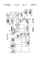
- FIG. 4 is a block diagram which illustrates the circuit for use in the camera-integrated video recorder according to the present invention.
- FIG. 5 is block diagram which illustrates the circuit for use in the camera-integrated video recorder according to another embodiment of the present invention.
- FIG. 1 is a perspective view which illustrates the camera-integrated video recorder according to the present invention and also illustrates a state in which a camera and recorder portion and a grip portion have been detached from each other when viewed from the rear side.
- FIG. 2 is a rear view of the state shown in FIG. 1 when viewed in the direction of the arrow "a" in FIG. 1.
- FIG. 3 is a perspective view which illustrates another usage state of the camera-integrated video recorder in which the camera and recorder portion and the grip portion have been detached from each other.
- reference numeral 1 represents a casing (to be called “a camera body” hereinafter) having a camera portion and a recorder portion.
- Reference numeral 2 represents an attachment base which is rotatably fastened to the camera body 1 by means of a rotary shaft 1a and to which a grip portion, to be described later, can be fastened.
- the attachment base 2 can be formed by bending its two sides in substantially U-shape facing side, the attachment base 2 having fastening grooves 2a and 2b arranged to be engaged with the grip portion to be described later so as to hold it.
- Reference numeral 3a represents a connector having a plurality of electric contacts through which signals pass between the camera body 1 and the grip portion, the electric contacts acting to supply power or the like when the grip to be described later is fastened.
- Reference numeral 4 represents a grip portion having an electronic viewfinder EVF, a zoom operating switch 8 and switches such as a recording trigger switch 7 for starting the recording operation. As is shown in FIG. 3, the grip portion 4 has a portion A for accommodating a power source battery therein so that the power source battery is accommodated in the grip portion 4.
- the grip portion 4 has, on its surface which is fastened to the camera body 1, a grip-side attachment 5 fixed thereto and having fastening projections 5a and 5b arranged to be engaged with the fastening grooves 2a and 2b formed in the attachment base 2 of the camera body 1. As designated by an arrow "b" shown in FIG. 1, the grip portion 4 can be fastened to the camera body 1 in such a manner that the attachment 5 of the grip portion 4 is moved from the rear portion of the camera body 1 along the fastening grooves 2a and 2b so as to be engaged with the attachment base 2.
- the fastening of the camera body 1 and the grip portion 4 also establishes an electric connection between the circuit connector 3a provided for the camera body 1 and a circuit connector 3b, (FIG. 4) to be described later, provided for the grip 4.
- the fastening state is locked by a locking mechanism 6.
- the grip portion 4 is rotatably fastened to the camera body 1, centering the rotary shaft 1a so that the most suitable camera angle can be made so as to correspond to a variety of photographing conditions.
- the circuit formed in the camera-integrated video recorder will be described with reference to FIG. 4.
- a photographing lens system 11 provided in the camera body 1 is photo-electrically converted by a camera-signal processing circuit 12, and is processed in a predetermined way so as to be converted into a TV signal. Then, the TV signal is supplied to a recorder portion 13. In the recorder portion 13, recording on a recording medium such as a magnetic tape is, if necessary, conducted in accordance with an operation of a user. All of the above-stated circuits are collectively controlled by a system control circuit 14.
- the above-stated TV signal is supplied to the connector 3a via the recorder portion 13 so that it is then transmitted to the grip-side connector 3b which is mechanically and electrically connected to the connector 3a, the TV signal being transmitted via a video signal line Vt.
- the TV signal is supplied to the electronic viewfinder EVF disposed in the grip portion 4 so that a picture which is being taken can be monitored.
- the user can control the recording action by operating various switches such as the zoom operating switch 8, the recording trigger switch 7 or the like while monitoring the picture displayed on the electronic viewfinder EVF.
- the control signals for conducting the above-stated controls are transmitted through a control signal line Vc.
- the state of the operation of an operation switch group 17 such as the zoom operating switch 8, the recording trigger switch 7, and the other switches disposed in the grip portion 4 is also supplied to the system control circuit 14 in the camera body 1 via the connectors 3a and 3b.
- the mode of the lens system 11, the camera signal processing circuit 12 and the recorder portion 13 are controlled in accordance with the state of the operation of the operation switch group 17.
- the camera body 1 is supplied with power from the power source battery B accommodated in the grip portion 4 via a power supply line Vb formed by the connectors 3a and 3b, while the grip-side circuit is directly supplied with power from the grip-side battery B.
- Another structure may be employed in which an output from the power source battery B is first supplied to a power supply voltage stabilizing circuit (omitted from illustration) provided for the camera body 1 via the connectors 3a and 3b so as to be a constant voltage, the output being then again transmitted through the connectors 3a and 3b so as to be supplied to each of the circuits in the grip portion 4.
- a power supply voltage stabilizing circuit (omitted from illustration) provided for the camera body 1 via the connectors 3a and 3b so as to be a constant voltage
- FIG. 5 is a block diagram which illustrates a second embodiment of the circuit according to the present invention.
- This embodiment is characterized in that the camera body 1 can be remote-controlled in such a manner that the grip portion 4 is arranged to act as a remote controller after it has been detached from the camera body 1.
- the same elements as those according to the first embodiment shown in FIG. 4 are given the same reference numerals and their descriptions are omitted here.
- a power source battery B' is provided for the camera body 1 in order to supply power to each of the circuits in the camera body 1. Furthermore, a control-signal receiving circuit 15 is also provided for the purpose of receiving an operation command signal from the remote controller which is the grip portion 4 detached from the camera body 1. The command signal from the remote controller is received by the receiving circuit 15 in which it is demodulated and decoded so as to be supplied to the system control circuit 14. As a result, the circuits in the camera body 1 are operated.
- a video signal transmission circuit 16 for supplying a signal in the recorder portion 13 to the grip portion 4 is provided.
- the above-stated circuits are switched by means of switched Sc1, Sc2, Sc3 and Sc4 which can be automatically switched in accordance with the connection/disconnection of the connectors 3a and 3b. These switches are switched to a contact "a" when the grip portion 4 is coupled to the camera body 1 and the connectors 3a and 3b are thereby connected to each other. As a result, power supply to the circuits from the camera-side battery B' is terminated but power from the grip-side battery B supplied via the power supply line Vb formed by the connectors 3a and 3b is supplied to the circuits in the camera body 1.
- the switches Sc1, Sc2, Sc3 and Sc4 are switched to a contact "b" so that all of the circuits in the camera body 1 are operated by the built-in battery B'. Also, the transmission circuit 16 and the receiving circuit 15 are supplied with power and thereby actuated.
- the grip portion 4 is provided with a receiving circuit 18 for receiving a video signal transmitted from the camera-side transmission circuit 16 and supplying it to the electronic viewfinder EVF when the grip portion 4 is detached, the grip portion 4 being further provided with a transmission circuit 19 for supplying an operation command signal generated by the operation switch group 17 in the grip portion 4 to the camera body 1.
- switches Sr1, Sr2 and Sr3 arranged to be switched in accordance with the connection/disconnection of the connectors 3a and 3b are provided for the grip potion 4. These switches are switched to the contact "a" when the grip portion 4 is coupled to the camera body 1 so that power supply to the transmission circuit 19 and the receiving circuit 18 in the grip portion 4 is terminated, but power from the battery power source B disposed in the grip portion 4 is supplied to the camera body 1 via the connectors 3a and 3b.
- a mode instruction signal corresponding to the operation of each of the switches of the operation switch group 17 is converted by the grip-side system control circuit 20 into a control signal which corresponds to the operation of each of the switches, the control signal being then supplied to the camera-side system control circuit 14 via the connectors 3a and 3b.
- the switches Sr1, Sr2 and Sr3 are switched to the contact "b" so that power is supplied to the receiving circuit 18 and the transmission circuit 19, causing these circuits to be actuated. Furthermore, the power supply via the connectors 3a and 3b is terminated.
- the mode instruction signal corresponding to the operation of the switches of the operation switch group 17 is converted by the grip-side system controller 20 into a control signal which corresponds to the operation of each of the switches, the control signal being then supplied to the transmission circuit 19 so that the instruction signal can be transmitted to the camera body 1.
- the battery B' in the camera body 1 is disconnected from the transmission circuit 16 and the receiving circuit 15 so that these circuits are turned off when the grip portion 4 is coupled to the camera body 1.
- both the transmission circuit 19 and the receiving circuit 18 in the grip portion 4 are disconnected from the battery B so that these circuits are turned off, power of the battery B being supplied to the camera body 1 via the power supply line Vb established by the connectors 3a and 3b.
- the operation instruction signal and the image signal to be monitored are transmitted through the control signal line Vc and the video signal line Vt established by the connectors 3a and 3b. Therefore, the same operating state as that according to the embodiment shown in FIG. 4 can be realized.
- the control instruction input terminal of the system control circuit 14 is switched from the connector to the receiving circuit 15 so that it receives the control instruction signal transmitted from the grip portion 4.
- the circuits are controlled in accordance with the contents of the control instruction signal.
- Each of the circuits in the grip portion 4 is supplied with power from the remote controller-side power source battery B so that the included receiving circuit 18 and the transmission circuit 19 are actuated.
- the operation instruction signal transmitted from the system control circuit 20 is transmitted to the camera body 1 via the transmission circuit 19. That is, the action of the camera body 1 can be remote-controlled by operating the operation switch group 17 provided for the grip portion 4.
- the video signal transmitted from the camera-side transmission circuit 19 is received by the receiving circuit 18 so as to be displayed on the electronic viewfinder EVF.
- the grip portion 4 can be used as the remote controller capable of controlling the action of the camera body 1 when the grip portion 4 has been detached from the camera body 1, the shooting can be freely conducted. Furthermore, when it is not used as the remote controller, it serves as the grip. Therefore, an independent space for the accommodation of the grip is not necessary, and losing or forgetting of the grip can be prevented.
- radio waves infrared rays or the like can be employed.
- analog-modulated infrared rays or digital-modulated infrared rays which are employed as usual remote controllers can be employed. Since these communication means can utilize the conventional means, its description is omitted here.
- the camera body is arranged in such a manner that the grip portion having the viewfinder and the camera and the recorder portions are rotatable with respect to each other and detachable. Therefore, the grip can be selected to correspond to the conditions of use and to meet the desires from the user. As a result, handling can be facilitated and the mobility can be improved.
- the grip portion can serve, when it is detached from the camera body, as the remote controller for remote-controlling the camera and the recorder portion, it can be used further widely.
Priority Applications (2)
| Application Number | Priority Date | Filing Date | Title |
|---|---|---|---|
| US08/164,993 US5381179A (en) | 1989-03-30 | 1993-12-10 | Camera-integrated video recorder apparatus |
| US08/723,374 US5696555A (en) | 1989-03-30 | 1996-09-30 | Image input apparatus having a detachably connected camera body and monitor or control unit |
Applications Claiming Priority (7)
| Application Number | Priority Date | Filing Date | Title |
|---|---|---|---|
| JP1-80883 | 1989-03-30 | ||
| JP1080883A JPH02260771A (ja) | 1989-03-30 | 1989-03-30 | カメラ一体型ビデオレコーダ装置 |
| US49990190A | 1990-03-27 | 1990-03-27 | |
| US68312291A | 1991-04-09 | 1991-04-09 | |
| US79835091A | 1991-11-21 | 1991-11-21 | |
| US90848692A | 1992-06-30 | 1992-06-30 | |
| US08/164,993 US5381179A (en) | 1989-03-30 | 1993-12-10 | Camera-integrated video recorder apparatus |
Related Parent Applications (1)
| Application Number | Title | Priority Date | Filing Date |
|---|---|---|---|
| US90848692A Continuation | 1989-03-30 | 1992-06-30 |
Related Child Applications (1)
| Application Number | Title | Priority Date | Filing Date |
|---|---|---|---|
| US31064594A Division | 1989-03-30 | 1994-09-22 |
Publications (1)
| Publication Number | Publication Date |
|---|---|
| US5381179A true US5381179A (en) | 1995-01-10 |
Family
ID=13730743
Family Applications (2)
| Application Number | Title | Priority Date | Filing Date |
|---|---|---|---|
| US08/164,993 Expired - Lifetime US5381179A (en) | 1989-03-30 | 1993-12-10 | Camera-integrated video recorder apparatus |
| US08/723,374 Expired - Fee Related US5696555A (en) | 1989-03-30 | 1996-09-30 | Image input apparatus having a detachably connected camera body and monitor or control unit |
Family Applications After (1)
| Application Number | Title | Priority Date | Filing Date |
|---|---|---|---|
| US08/723,374 Expired - Fee Related US5696555A (en) | 1989-03-30 | 1996-09-30 | Image input apparatus having a detachably connected camera body and monitor or control unit |
Country Status (2)
| Country | Link |
|---|---|
| US (2) | US5381179A (ja) |
| JP (1) | JPH02260771A (ja) |
Cited By (29)
| Publication number | Priority date | Publication date | Assignee | Title |
|---|---|---|---|---|
| US5486852A (en) * | 1990-05-22 | 1996-01-23 | Canon Kabushiki Kaisha | Camera-integrated video recorder system having mountable and demountable remote-control unit |
| WO1996021173A1 (en) * | 1994-12-29 | 1996-07-11 | Motorola Inc. | Wireless pager with separable receiver unit and transmitter unit |
| US5659361A (en) * | 1994-03-10 | 1997-08-19 | Lg Electronics Inc. | Tiltable, rotatable and detachable LCD viewfinder |
| US5748238A (en) * | 1992-03-12 | 1998-05-05 | Hitachi, Ltd. | Video camera |
| US5764031A (en) * | 1993-08-25 | 1998-06-09 | Sony Corporation | Method and apparatus for supplying a power source to an electronic apparatus |
| US5815126A (en) * | 1993-10-22 | 1998-09-29 | Kopin Corporation | Monocular portable communication and display system |
| US5844604A (en) * | 1994-12-19 | 1998-12-01 | Lg Electronics, Inc. | Camcorder having separable camera unit and recorder unit |
| US6011365A (en) * | 1997-01-14 | 2000-01-04 | Matsushita Electric Industrial Co., Ltd. | Electromagnetic focus apparatus |
| US6073034A (en) * | 1996-10-31 | 2000-06-06 | Kopin Corporation | Wireless telephone display system |
| US6148141A (en) * | 1996-05-10 | 2000-11-14 | Canon Kabushiki Kaisha | Image pickup system with separable/attachable image pickup device and display device |
| US20010017604A1 (en) * | 1996-10-31 | 2001-08-30 | Jeffrey Jacobsen | Reflective microdisplay for portable communication system |
| US20010054989A1 (en) * | 1993-10-22 | 2001-12-27 | Matthew Zavracky | Color sequential display panels |
| US6421031B1 (en) | 1993-10-22 | 2002-07-16 | Peter A. Ronzani | Camera display system |
| US6424321B1 (en) | 1993-10-22 | 2002-07-23 | Kopin Corporation | Head-mounted matrix display |
| US6448944B2 (en) | 1993-10-22 | 2002-09-10 | Kopin Corporation | Head-mounted matrix display |
| US20020158823A1 (en) * | 1997-10-31 | 2002-10-31 | Matthew Zavracky | Portable microdisplay system |
| US6476784B2 (en) | 1997-10-31 | 2002-11-05 | Kopin Corporation | Portable display system with memory card reader |
| US6552704B2 (en) | 1997-10-31 | 2003-04-22 | Kopin Corporation | Color display with thin gap liquid crystal |
| US20040051811A1 (en) * | 2002-09-13 | 2004-03-18 | Yutaka Nakanishi | Camera-equipped recording/reproducing apparatus |
| US20040169955A1 (en) * | 2002-02-13 | 2004-09-02 | Yoshihisa Tsuchida | Magnetic recording/reproducing device |
| US20050174480A1 (en) * | 2004-02-10 | 2005-08-11 | Pentax Corporation | Digital camera |
| US20050174479A1 (en) * | 2004-02-10 | 2005-08-11 | Pentax Corporation | Digital camera |
| US20050261025A1 (en) * | 2004-05-20 | 2005-11-24 | Koji Kogusuri | Image reproduction apparatus |
| US7321354B1 (en) | 1996-10-31 | 2008-01-22 | Kopin Corporation | Microdisplay for portable communication systems |
| US7372447B1 (en) | 1996-10-31 | 2008-05-13 | Kopin Corporation | Microdisplay for portable communication systems |
| US20100123799A1 (en) * | 2008-11-19 | 2010-05-20 | Asia Optical Co., Inc. | Image capturing apparatus |
| US20100123791A1 (en) * | 2008-11-19 | 2010-05-20 | Samsung Digital Imaging Co., Ltd. | Digital image processing apparatus and method of controlling the same |
| US11016372B2 (en) * | 2019-05-10 | 2021-05-25 | Canon Kabushiki Kaisha | Electronic apparatus to which accessory is removably attached, accessory, and system |
| GB2596044A (en) * | 2020-04-10 | 2021-12-22 | Henning Victor | Controlling a portable electronic device with camera |
Families Citing this family (6)
| Publication number | Priority date | Publication date | Assignee | Title |
|---|---|---|---|---|
| US5642458A (en) * | 1992-11-18 | 1997-06-24 | Canon Kabushiki Kaisha | Video signal processing apparatus |
| US5844606A (en) * | 1994-03-03 | 1998-12-01 | Fuji Photo Film Co., Ltd. | Videocamera having a multiconnector connectable to a variety of accessories |
| US6927797B2 (en) * | 2001-04-19 | 2005-08-09 | Panavision Inc. | Viewfinder for high definition video camera |
| TWI313782B (en) * | 2003-04-14 | 2009-08-21 | Tai Her Yang | Combined or standalone hand-held a/v camera system |
| US7733370B2 (en) * | 2005-04-08 | 2010-06-08 | Autoliv Asp, Inc. | Night vision camera mount quick disconnect |
| US11451700B2 (en) | 2019-03-06 | 2022-09-20 | Aob Products Company | Game camera having camera control module |
Citations (14)
| Publication number | Priority date | Publication date | Assignee | Title |
|---|---|---|---|---|
| JPS58195370A (ja) * | 1982-05-10 | 1983-11-14 | Mitsubishi Electric Corp | ビデオカメラ |
| US4420773A (en) * | 1980-06-30 | 1983-12-13 | Nippon Kogaku K.K. | Electronic photographic camera |
| JPS59158175A (ja) * | 1983-02-28 | 1984-09-07 | Nippon Kogaku Kk <Nikon> | ビデオカメラ |
| US4550343A (en) * | 1983-07-15 | 1985-10-29 | Olympus Optical Co., Ltd. | Video camera apparatus |
| US4625243A (en) * | 1982-05-25 | 1986-11-25 | Victor Company Of Japan, Limited | Hand-held TV camera |
| EP0203783A2 (en) * | 1985-05-27 | 1986-12-03 | Sony Corporation | Video tape recorder having built-in camera |
| US4682240A (en) * | 1985-06-07 | 1987-07-21 | Robert Bosch Gmbh | Interlocked television camera and electronic viewfinder combination |
| JPS6374044A (ja) * | 1986-09-18 | 1988-04-04 | Sony Corp | スチルカメラ付ビデオカメラ |
| JPS6377040A (ja) * | 1986-09-19 | 1988-04-07 | Sony Corp | スチルカメラ付ビデオカメラ |
| JPS6421830A (en) * | 1987-06-26 | 1989-01-25 | Vacuumschmelze Gmbh | Manufacture and application of line-type and/or belt-type superconductor |
| US4959729A (en) * | 1987-11-25 | 1990-09-25 | Fuji Photo Film Co., Ltd. | Video camera having rotatable viewfinder |
| US4963987A (en) * | 1987-11-06 | 1990-10-16 | Canon Kabushiki Kaisha | Video camera apparatus with grip axis and viewfinder optical axis in parallel relation |
| US4965462A (en) * | 1987-08-31 | 1990-10-23 | Frezzolini Electronics Inc. | Stand-by power supply |
| US5119203A (en) * | 1988-02-16 | 1992-06-02 | Casio Computer Co., Ltd. | Monitor mounting fixture |
-
1989
- 1989-03-30 JP JP1080883A patent/JPH02260771A/ja active Pending
-
1993
- 1993-12-10 US US08/164,993 patent/US5381179A/en not_active Expired - Lifetime
-
1996
- 1996-09-30 US US08/723,374 patent/US5696555A/en not_active Expired - Fee Related
Patent Citations (14)
| Publication number | Priority date | Publication date | Assignee | Title |
|---|---|---|---|---|
| US4420773A (en) * | 1980-06-30 | 1983-12-13 | Nippon Kogaku K.K. | Electronic photographic camera |
| JPS58195370A (ja) * | 1982-05-10 | 1983-11-14 | Mitsubishi Electric Corp | ビデオカメラ |
| US4625243A (en) * | 1982-05-25 | 1986-11-25 | Victor Company Of Japan, Limited | Hand-held TV camera |
| JPS59158175A (ja) * | 1983-02-28 | 1984-09-07 | Nippon Kogaku Kk <Nikon> | ビデオカメラ |
| US4550343A (en) * | 1983-07-15 | 1985-10-29 | Olympus Optical Co., Ltd. | Video camera apparatus |
| EP0203783A2 (en) * | 1985-05-27 | 1986-12-03 | Sony Corporation | Video tape recorder having built-in camera |
| US4682240A (en) * | 1985-06-07 | 1987-07-21 | Robert Bosch Gmbh | Interlocked television camera and electronic viewfinder combination |
| JPS6374044A (ja) * | 1986-09-18 | 1988-04-04 | Sony Corp | スチルカメラ付ビデオカメラ |
| JPS6377040A (ja) * | 1986-09-19 | 1988-04-07 | Sony Corp | スチルカメラ付ビデオカメラ |
| JPS6421830A (en) * | 1987-06-26 | 1989-01-25 | Vacuumschmelze Gmbh | Manufacture and application of line-type and/or belt-type superconductor |
| US4965462A (en) * | 1987-08-31 | 1990-10-23 | Frezzolini Electronics Inc. | Stand-by power supply |
| US4963987A (en) * | 1987-11-06 | 1990-10-16 | Canon Kabushiki Kaisha | Video camera apparatus with grip axis and viewfinder optical axis in parallel relation |
| US4959729A (en) * | 1987-11-25 | 1990-09-25 | Fuji Photo Film Co., Ltd. | Video camera having rotatable viewfinder |
| US5119203A (en) * | 1988-02-16 | 1992-06-02 | Casio Computer Co., Ltd. | Monitor mounting fixture |
Cited By (47)
| Publication number | Priority date | Publication date | Assignee | Title |
|---|---|---|---|---|
| US5486852A (en) * | 1990-05-22 | 1996-01-23 | Canon Kabushiki Kaisha | Camera-integrated video recorder system having mountable and demountable remote-control unit |
| US5748238A (en) * | 1992-03-12 | 1998-05-05 | Hitachi, Ltd. | Video camera |
| US5764031A (en) * | 1993-08-25 | 1998-06-09 | Sony Corporation | Method and apparatus for supplying a power source to an electronic apparatus |
| US8040292B2 (en) | 1993-10-22 | 2011-10-18 | Kopin Corporation | Portable communication display device |
| US6421031B1 (en) | 1993-10-22 | 2002-07-16 | Peter A. Ronzani | Camera display system |
| US6452572B1 (en) | 1993-10-22 | 2002-09-17 | Kopin Corporation | Monocular head-mounted display system |
| US6448944B2 (en) | 1993-10-22 | 2002-09-10 | Kopin Corporation | Head-mounted matrix display |
| US6424321B1 (en) | 1993-10-22 | 2002-07-23 | Kopin Corporation | Head-mounted matrix display |
| US5815126A (en) * | 1993-10-22 | 1998-09-29 | Kopin Corporation | Monocular portable communication and display system |
| US20010054989A1 (en) * | 1993-10-22 | 2001-12-27 | Matthew Zavracky | Color sequential display panels |
| US6683584B2 (en) | 1993-10-22 | 2004-01-27 | Kopin Corporation | Camera display system |
| US7310072B2 (en) | 1993-10-22 | 2007-12-18 | Kopin Corporation | Portable communication display device |
| US20080122736A1 (en) * | 1993-10-22 | 2008-05-29 | Kopin Corporation | Portable communication display device |
| US5659361A (en) * | 1994-03-10 | 1997-08-19 | Lg Electronics Inc. | Tiltable, rotatable and detachable LCD viewfinder |
| US5844604A (en) * | 1994-12-19 | 1998-12-01 | Lg Electronics, Inc. | Camcorder having separable camera unit and recorder unit |
| WO1996021173A1 (en) * | 1994-12-29 | 1996-07-11 | Motorola Inc. | Wireless pager with separable receiver unit and transmitter unit |
| GB2301467B (en) * | 1994-12-29 | 1998-07-15 | Motorola Inc | Wireless pager with separable receiver unit and transmitter unit |
| GB2301467A (en) * | 1994-12-29 | 1996-12-04 | Motorola Inc | Wireless pager with separable receiver unit and transmitter unit |
| US5584070A (en) * | 1994-12-29 | 1996-12-10 | Motorola, Inc. | Wireless pager with separable receiver unit and transmitter unit |
| US6148141A (en) * | 1996-05-10 | 2000-11-14 | Canon Kabushiki Kaisha | Image pickup system with separable/attachable image pickup device and display device |
| US6978085B1 (en) | 1996-05-10 | 2005-12-20 | Canon Kabushiki Kaisha | Image pickup system with separable/attachable image pickup device and display device |
| US6073034A (en) * | 1996-10-31 | 2000-06-06 | Kopin Corporation | Wireless telephone display system |
| US6486862B1 (en) | 1996-10-31 | 2002-11-26 | Kopin Corporation | Card reader display system |
| US6677936B2 (en) | 1996-10-31 | 2004-01-13 | Kopin Corporation | Color display system for a camera |
| US6232937B1 (en) | 1996-10-31 | 2001-05-15 | Kopin Corporation | Low power active display system |
| US7372447B1 (en) | 1996-10-31 | 2008-05-13 | Kopin Corporation | Microdisplay for portable communication systems |
| US7321354B1 (en) | 1996-10-31 | 2008-01-22 | Kopin Corporation | Microdisplay for portable communication systems |
| US20010017604A1 (en) * | 1996-10-31 | 2001-08-30 | Jeffrey Jacobsen | Reflective microdisplay for portable communication system |
| US6011365A (en) * | 1997-01-14 | 2000-01-04 | Matsushita Electric Industrial Co., Ltd. | Electromagnetic focus apparatus |
| US7242383B2 (en) | 1997-10-31 | 2007-07-10 | Kopin Corporation | Portable microdisplay system |
| US6552704B2 (en) | 1997-10-31 | 2003-04-22 | Kopin Corporation | Color display with thin gap liquid crystal |
| US20020158823A1 (en) * | 1997-10-31 | 2002-10-31 | Matthew Zavracky | Portable microdisplay system |
| US6476784B2 (en) | 1997-10-31 | 2002-11-05 | Kopin Corporation | Portable display system with memory card reader |
| US6909419B2 (en) | 1997-10-31 | 2005-06-21 | Kopin Corporation | Portable microdisplay system |
| US6972925B2 (en) * | 2002-02-13 | 2005-12-06 | Sony Corporation | Miniaturized video cassette camera including a rotatable grip member |
| US20040169955A1 (en) * | 2002-02-13 | 2004-09-02 | Yoshihisa Tsuchida | Magnetic recording/reproducing device |
| US20040051811A1 (en) * | 2002-09-13 | 2004-03-18 | Yutaka Nakanishi | Camera-equipped recording/reproducing apparatus |
| US7339624B2 (en) * | 2002-09-13 | 2008-03-04 | Victor Company Of Japan, Ltd. | Camera-equipped recording/reproducing apparatus |
| US20050174480A1 (en) * | 2004-02-10 | 2005-08-11 | Pentax Corporation | Digital camera |
| US20050174479A1 (en) * | 2004-02-10 | 2005-08-11 | Pentax Corporation | Digital camera |
| US7477318B2 (en) * | 2004-02-10 | 2009-01-13 | Hoya Corporation | Manual operational member positioning on rotatable grip of digital camera |
| US8009220B2 (en) * | 2004-05-20 | 2011-08-30 | Canon Kabushiki Kaisha | Image reproduction apparatus |
| US20050261025A1 (en) * | 2004-05-20 | 2005-11-24 | Koji Kogusuri | Image reproduction apparatus |
| US20100123799A1 (en) * | 2008-11-19 | 2010-05-20 | Asia Optical Co., Inc. | Image capturing apparatus |
| US20100123791A1 (en) * | 2008-11-19 | 2010-05-20 | Samsung Digital Imaging Co., Ltd. | Digital image processing apparatus and method of controlling the same |
| US11016372B2 (en) * | 2019-05-10 | 2021-05-25 | Canon Kabushiki Kaisha | Electronic apparatus to which accessory is removably attached, accessory, and system |
| GB2596044A (en) * | 2020-04-10 | 2021-12-22 | Henning Victor | Controlling a portable electronic device with camera |
Also Published As
| Publication number | Publication date |
|---|---|
| US5696555A (en) | 1997-12-09 |
| JPH02260771A (ja) | 1990-10-23 |
Similar Documents
| Publication | Publication Date | Title |
|---|---|---|
| US5381179A (en) | Camera-integrated video recorder apparatus | |
| KR100570163B1 (ko) | 디지털 카메라 시스템 | |
| KR920007919B1 (ko) | 텔레비젼 전화기 | |
| US6128441A (en) | Waterproof case for camera | |
| JP3476910B2 (ja) | 撮像装置 | |
| EP0487330B1 (en) | Image processing system | |
| US5729291A (en) | Video camera with compact arrangement of parts | |
| JP3108805B2 (ja) | ビデオカメラ | |
| JPH10191128A (ja) | 撮像装置 | |
| KR20080041007A (ko) | 외장카메라들을 구비한 촬영장치 및 그의 모드 전환방법 | |
| JPH10333233A (ja) | 撮像装置及びその防水具 | |
| JP2558360B2 (ja) | 三脚兼用グリップ | |
| JPS62235880A (ja) | ビデオカメラ | |
| JPH1098641A (ja) | 撮像装置 | |
| JP2585813B2 (ja) | ビデオカメラのアクセサリー | |
| JP2601935B2 (ja) | リモコン装置 | |
| JP2935461B2 (ja) | 電子カメラシステム | |
| JP3089703B2 (ja) | ビデオカメラのバッテリー充電装置 | |
| JP3109824B2 (ja) | カメラ装置 | |
| JPS58195370A (ja) | ビデオカメラ | |
| JP2935498B2 (ja) | 電子機器における接続装置 | |
| JPH11177863A (ja) | レンズの操作装置 | |
| JP3327931B2 (ja) | 外部制御装置 | |
| JPH09116797A (ja) | 光学系分離型信号記録再生装置 | |
| JPH01228273A (ja) | ビデオカメラ |
Legal Events
| Date | Code | Title | Description |
|---|---|---|---|
| STCF | Information on status: patent grant |
Free format text: PATENTED CASE |
|
| CC | Certificate of correction | ||
| FEPP | Fee payment procedure |
Free format text: PAYOR NUMBER ASSIGNED (ORIGINAL EVENT CODE: ASPN); ENTITY STATUS OF PATENT OWNER: LARGE ENTITY |
|
| FPAY | Fee payment |
Year of fee payment: 4 |
|
| FEPP | Fee payment procedure |
Free format text: PAYER NUMBER DE-ASSIGNED (ORIGINAL EVENT CODE: RMPN); ENTITY STATUS OF PATENT OWNER: LARGE ENTITY Free format text: PAYOR NUMBER ASSIGNED (ORIGINAL EVENT CODE: ASPN); ENTITY STATUS OF PATENT OWNER: LARGE ENTITY |
|
| FPAY | Fee payment |
Year of fee payment: 8 |
|
| FPAY | Fee payment |
Year of fee payment: 12 |