US4969005A - Backlighting detecting device - Google Patents
Backlighting detecting device Download PDFInfo
- Publication number
- US4969005A US4969005A US07/345,444 US34544489A US4969005A US 4969005 A US4969005 A US 4969005A US 34544489 A US34544489 A US 34544489A US 4969005 A US4969005 A US 4969005A
- Authority
- US
- United States
- Prior art keywords
- area
- areas
- luminance
- luminance value
- detecting
- Prior art date
- Legal status (The legal status is an assumption and is not a legal conclusion. Google has not performed a legal analysis and makes no representation as to the accuracy of the status listed.)
- Expired - Lifetime
Links
- 238000001514 detection method Methods 0.000 claims description 16
- 235000019557 luminance Nutrition 0.000 description 24
- 238000000034 method Methods 0.000 description 6
- 230000008569 process Effects 0.000 description 6
- 238000005259 measurement Methods 0.000 description 5
- 239000000203 mixture Substances 0.000 description 5
- 238000010586 diagram Methods 0.000 description 4
- 230000006835 compression Effects 0.000 description 3
- 238000007906 compression Methods 0.000 description 3
- 230000003287 optical effect Effects 0.000 description 3
- 230000011514 reflex Effects 0.000 description 3
- 230000035945 sensitivity Effects 0.000 description 3
- XUIMIQQOPSSXEZ-UHFFFAOYSA-N Silicon Chemical compound [Si] XUIMIQQOPSSXEZ-UHFFFAOYSA-N 0.000 description 2
- 239000003990 capacitor Substances 0.000 description 2
- 238000009432 framing Methods 0.000 description 2
- 229910052710 silicon Inorganic materials 0.000 description 2
- 239000010703 silicon Substances 0.000 description 2
- 230000004075 alteration Effects 0.000 description 1
- 230000008901 benefit Effects 0.000 description 1
- 230000008859 change Effects 0.000 description 1
- 230000006872 improvement Effects 0.000 description 1
- 230000000977 initiatory effect Effects 0.000 description 1
- 238000004519 manufacturing process Methods 0.000 description 1
Images


Classifications
-
- G—PHYSICS
- G03—PHOTOGRAPHY; CINEMATOGRAPHY; ANALOGOUS TECHNIQUES USING WAVES OTHER THAN OPTICAL WAVES; ELECTROGRAPHY; HOLOGRAPHY
- G03B—APPARATUS OR ARRANGEMENTS FOR TAKING PHOTOGRAPHS OR FOR PROJECTING OR VIEWING THEM; APPARATUS OR ARRANGEMENTS EMPLOYING ANALOGOUS TECHNIQUES USING WAVES OTHER THAN OPTICAL WAVES; ACCESSORIES THEREFOR
- G03B7/00—Control of exposure by setting shutters, diaphragms or filters, separately or conjointly
- G03B7/28—Circuitry to measure or to take account of the object contrast
-
- G—PHYSICS
- G03—PHOTOGRAPHY; CINEMATOGRAPHY; ANALOGOUS TECHNIQUES USING WAVES OTHER THAN OPTICAL WAVES; ELECTROGRAPHY; HOLOGRAPHY
- G03B—APPARATUS OR ARRANGEMENTS FOR TAKING PHOTOGRAPHS OR FOR PROJECTING OR VIEWING THEM; APPARATUS OR ARRANGEMENTS EMPLOYING ANALOGOUS TECHNIQUES USING WAVES OTHER THAN OPTICAL WAVES; ACCESSORIES THEREFOR
- G03B7/00—Control of exposure by setting shutters, diaphragms or filters, separately or conjointly
- G03B7/08—Control effected solely on the basis of the response, to the intensity of the light received by the camera, of a built-in light-sensitive device
- G03B7/091—Digital circuits
-
- G—PHYSICS
- G03—PHOTOGRAPHY; CINEMATOGRAPHY; ANALOGOUS TECHNIQUES USING WAVES OTHER THAN OPTICAL WAVES; ELECTROGRAPHY; HOLOGRAPHY
- G03B—APPARATUS OR ARRANGEMENTS FOR TAKING PHOTOGRAPHS OR FOR PROJECTING OR VIEWING THEM; APPARATUS OR ARRANGEMENTS EMPLOYING ANALOGOUS TECHNIQUES USING WAVES OTHER THAN OPTICAL WAVES; ACCESSORIES THEREFOR
- G03B7/00—Control of exposure by setting shutters, diaphragms or filters, separately or conjointly
- G03B7/08—Control effected solely on the basis of the response, to the intensity of the light received by the camera, of a built-in light-sensitive device
- G03B7/099—Arrangement of photoelectric elements in or on the camera
- G03B7/0993—Arrangement of photoelectric elements in or on the camera in the camera
- G03B7/0997—Through the lens [TTL] measuring
- G03B7/09971—Through the lens [TTL] measuring in mirror-reflex cameras
- G03B7/09974—Through the lens [TTL] measuring in mirror-reflex cameras using the film or shutter as sensor light reflecting member
-
- G—PHYSICS
- G03—PHOTOGRAPHY; CINEMATOGRAPHY; ANALOGOUS TECHNIQUES USING WAVES OTHER THAN OPTICAL WAVES; ELECTROGRAPHY; HOLOGRAPHY
- G03B—APPARATUS OR ARRANGEMENTS FOR TAKING PHOTOGRAPHS OR FOR PROJECTING OR VIEWING THEM; APPARATUS OR ARRANGEMENTS EMPLOYING ANALOGOUS TECHNIQUES USING WAVES OTHER THAN OPTICAL WAVES; ACCESSORIES THEREFOR
- G03B7/00—Control of exposure by setting shutters, diaphragms or filters, separately or conjointly
- G03B7/08—Control effected solely on the basis of the response, to the intensity of the light received by the camera, of a built-in light-sensitive device
- G03B7/099—Arrangement of photoelectric elements in or on the camera
- G03B7/0993—Arrangement of photoelectric elements in or on the camera in the camera
- G03B7/0997—Through the lens [TTL] measuring
- G03B7/09979—Multi-zone light measuring
Definitions
- This invention relates to a backlighting detecting device for performing detection of the backlighting condition of a field of view.
- the necessity of detecting the backlighting condition of a field of view arises in a situation where the luminance difference between a main subject portion and a background portion of a scene is so great that it is difficult to derive a proper exposure value for both the subject and the background.
- the scene is such as that if the exposure is adjusted for the subject by using the spot light measuring mode or the like, a considerably large over-exposure will result in the portion of the background, because it is of high luminance.
- the use of the center-weighted average light measurement in view of a proper exposure over the entire area of the picture frame on the other hand, will result in considerable under-exposure of the portion of the subject, because it is relatively low in luminance.
- automatic fill-in flash may be fired. If so, even in such a scene, a good photograph can be taken of a portion of the subject saved from under-exposure, while nevertheless properly exposing a to portion of the background.
- a light sensor responsive to the entire field of view and another light sensor responsive to a portion of the field of view are used in combination with a light measuring circuit, so that backlighting is detected by finding the difference between the two light values, as, for example, in Japanese Patent Publication No. Sho 47-34343.
- Another type a disclosed in Japanese Laid-Open Patent Application No. Sho 57-29036 is that the field of view is divided into a plurality of areas in which light measurement is performed, and the largest and smallest values are used in computation to detect the backlighting condition.
- the light sensor for the integral field of view does not produce an output representing a very high light value. Even with a backlighting scene, therefore, some cases may be encountered where the backlighting condition is not detected as it stands.
- a goal of the present invention is to assure detection of true backlighting accurately and reliably particularly in photographic situations where the field surrounding the subject consists of a mixture of luminous areas and dark areas.
- One object of the invention is to provide a backlighting detecting device in which the field of view is divided into at least three concentric areas, namely, a central area, a first outer area adjacent the center, and a second outer area, so that the luminances of all the areas are individually measured and then compared with one another, whereby when the first outer area is more luminous than the central area by more than a first predetermined value, and when the second outer area is more luminous than the first outer area by more than a second predetermined value, the given lighting condition is detected as a backlighting condition.
- FIG. 1 is a schematic view of the optical system of an embodiment according to the invention applied to a single-lens reflex camera.
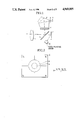
- FIG. 2 is a plan view for of the division of the light receiving surface of the photosensitive means of FIG. 1 into a plurality of areas.
- FIG. 3 is an electrical circuit diagram of an embodiment of the invention.
- FIG. 4 is a flowchart of the embodiment of the invention.
- FIG. 5 is a diagram for explaining the expression of a backlighting detecting algorithm of the embodiment of the invention.
- FIG. 6 is a flowchart of the sequence of the complete operation to take a shot.
- FIG. 1 in sectional view schematically shows the optical system of the single-lens reflex camera to which the invention is applied.
- the optical system comprises an interchangeable photographic lens 1, a quick-return mirror 2, a focusing screen 3, a pentagonal roof type prism 4, an image forming lens 5, a light meter 6, an image plane (film plane, or CCD surface) 7, and a flash adjusting sensor 20.
- FIG. 2 shows, in enlarged scale, the light receiving surface of the light meter 6 shown in FIG. 1.
- A denotes a central area of the field of view
- B denotes an intermediate area surrounding area A
- C denotes a marginal area divided into four parts C 1 -C 4 .
- the field of view is divided into six areas A, B and C 1 to C 4 , and the luminance of the field of view is measured by each area.
- FIG. 3 is an electrical circuit diagram, partly in block form, of the embodiment of the invention.
- FIG. 4 is a flowchart for the operation of the circuit of FIG. 3.
- FIG. 5 shows an algorithm for detection of the backlighting.
- FIG. 3 six silicon photodiodes (SPDs) 8, 9, 10, 11, 12 and 13 corresponding to the above-described six areas A, B, C 1 , C 2 , C 3 and C 4 respectively produce photocurrents i A , i B , i C1 , i C2 , i C3 and i C4 proportional to the luminances of the respective areas.
- These photocurrents are logarithmically compressed by the respective logarithmic compression circuits 14 to 19, which produce outputs in the form of voltage values V A , V B , V C1 , V C2 , V C3 and V C4 .
- a multiplexer 21 receptive of the voltage values V A , V B , V C1 , V C2 , V C3 and V C4 at its input terminals I 11 to I 16 , respectively, and responsive to signals arriving at its input terminals S 0 , S 1 and S 2 from a CPU 22 for performing various kinds of computation for control, places one of them selectively onto its output terminal O 17 .
- An AF (Auto-Focus) unit 32 of the phase difference detection type known to those skilled in the art when receiving a signal from a terminal AFS of the CPU 22, carries out an AF operation to drive a focusing lens (not shown) axially, and, when it terminates, sends a signal back to a terminal AFE of the CPU 22.
- An A/D converter 33 receptive of the output from the terminal O 17 of the multiplexer 21 produces an output proportional to the luminance in digital form of the voltage value, which is supplied to the CPU 22.
- a silicon photodiode (SPD) 26 in the flash adjusting sensor 20 (see FIG. 1) generates a photocurrent i S proportional to the reflection of the light impinging on the image plane 7.
- the flash adjusting circuit 24 operates like the logarithmic compression circuits 14-19 to produce an output in the form of a voltage value V S proportional to the logarithm of the photocurrent i S .
- a signal is inputted to a terminal STA and the flash adjusting circuit 24 starts to integrate the product of the voltage value V S with a gain.
- This gain has a value representing the sensitivity in ISO of the used film sent from the CPU 22 through a D/A converter 25 when a DX-code reading circuit 27 reads information relating to the ISO sensitivity.
- a flash emission stop signal is sent from a terminal STP of the flash adjusting circuit 24 to a flash unit 23.
- the flash unit 23 comprises a boosting electric power source circuit 28, a trigger circuit 29, a flash discharge tube 30, and a thyristor circuit 31. Responsive to closure of an electric power source switch SW2, or a signal from a terminal POWER of the CPU 22, the boosting electric power source circuit 28 starts charging onto a main discharge capacitor (not shown) for the purpose of flash emission.
- the capacitor After the capacitor is fully charged, it sends a signal to a terminal CHR of the CPU 22.
- the trigger circuit 29 causes the flash discharge tube 30 to start flash emission.
- the flash emission stop signal from the flash adjusting circuit 24 (the signal of the terminal STP)
- the thyristor circuit 31 causes the flash discharge tube 30 to stop the flash emission. Again, the thyristor circuit 31 prohibits the flash discharge tube 30 from being fired for flash emission when a signal is output from a terminal DIS of the CPU 22.
- the CPU 22 produces six different patterns of the signals at the terminals S 0 , S 1 and S 2 successively, and in turn serially receives all the luminances of the 6-divided light measuring sensor.
- the six luminances are stored in a memory at successive addresses A BV , B BV , C 1BV , C 2BV , C 3BV and C 4BV respectively, and computation is performed as follows:
- the values of the luminances C 1BV -C 4BV are averaged to obtain a luminance C BV in a step S1.
- a BV ⁇ T DARK ⁇ BV (where T DARK ⁇ BV : A low luminance threshold level for automatic flash emission) is found in a step S2
- the process advances to a step S7 to render operative the automatic flash emission mode.
- a BV ⁇ T DARK ⁇ BV then B BV -A BV and C BV -B BV are determined in a step S3 and a step S8, respectively, to determine whether they are are after than respective predetermined levels T 1BV and T 2BV .
- step S7 determines whether the process is operative the automatic flash emission mode, because the given situation is determined to be a backlighting condition. Otherwise, the process advances to a step S4.
- step S4 largest value among the luminances C 1BV -C 4BV is designated as C max ⁇ BV to take its difference from the luminance B BV . If the difference is not less than a predetermined level T BV determined in a step S5, then the process advances to the step S7 to render operative the automatic flash emission mode because of the detection of a backlighting condition. Otherwise, the process advances to a step S6.
- the CPU 22 When the automatic flash emission mode with the flash unit is set in step S7, the CPU 22 produces a signal at the terminal POWER to command a initiation of a charging the flash unit. Then, upon receipt of the signal at the terminal CHR, the CPU 22 terminates the charging. Incidentally, the CPU 22 does not produce the signal at the terminal DIS. In the step S6, on the other hand, because the flash non-emission mode is rendered operative, the CPU 22 produces the signal at the terminal DIS to prohibit flash emission from occurring.
- the CPU 22 determines an exposure value. This is derived by computing a value based on the formula:
- FIG. 5 depicts the algorithm of the backlighting detection in the steps S3 and S8 for the purpose of better understanding.
- B BV -A BV ⁇ T 1BV may result when the subject in the field of view is just equal in size to the area A of the light measuring surface of the light meter 6, and the background occupies the intermediate area B, and when the luminance difference between the subject and the background is higher than the predetermined level T 1BV , or the subject is darker.
- the given lighting situation can be judged as the backlighting one.
- the area C is darker than the area B. That is, among the light measuring areas A, B and C, only the area B is luminous. This cannot be said in the general case to be a backlighting scene. Therefore, this situation is not judged as a backlighting condition.
- the light measuring area C Since the light measuring area C is responsive to the margin of the field of view, it is expected in some scenes that the sky and the earth or a mixture of various luminances enter the picture at once.
- the intermediate light measuring area B a size equal to the sum of the area A and the area B,
- the use of the average of the area C in comparison with the area B does not always assure production of an appreciable difference between C BV and B BV as in the landscape with a clear sky and a shadowed foreground. So, the backlighting detection cannot be reliably performed (in the figure, ⁇ ).
- C max ⁇ BV in computing the difference from between B BV , when backlighting detection is performed.
- the invention makes it possible to limit the effective backlighting detection just to the true backlighting situations such as that when a luminous portion of the field of view lies in the background, while the subject is shadowed against it.
- FIG. 6 shows a flow diagram of all the operational steps to take a shot.
- the photographer first puts a main object in registry with the central portion of the field of view and then pushes the shutter button to a half stroke (step S10).
- the camera responsive to that aligned field of view performs the AF operation and the AE operation and locks them individually (steps S11-S13). It is to be noted here that if the photographer removes his finger from half-pushed position of the shutter button, the AF operation and the AE operation are unlocked and the camera returns to the initial position (step S14).
- the photographer while keeping the shutter button in the half-pushed position may change the framing until a desired composition is attained, and then further pushes the shutter button to the full stroke (step S15).
- the camera focuses the lens on the main object and makes a proper exposure for the main object. If the main object is backlighted, the flash unit is fired when the camera release is actuated (step S16). When the release sequence ends, a film transport is automatically carried out (step S17). Thus, the camera returns to the initial position. If his desired framing is with the main object at the center of the field of view, the photographer may push the shutter button straight to the full stroke. In this case, the above-described shooting operation sequences without the loops.
- the embodiment has been described in connection with the light measuring sensor of the type operating in three radially divided areas from the central portion of the field of view to the margin and four circumferentially divided sections of the marginal area, another type of light measuring sensor having a greater number of areas and sections may be used to achieve a further improvement of the accuracy and reliability.
- the flash unit may be either independent of the camera or built in the camera.
- each of the threshold levels T 1BV , T 2BV and T BV for backlighting detection may otherwise be made adjustable depending on the situation. If so, delicate alteration of the threshold levels according to the luminance C BV which takes different values on the assumption that the day is fine or overcast will lead to a possibility of performing a better backlighting detection.
- the computations and the backlighting detection besides their being performed by using a microcomputer with software, may otherwise be performed by using hardware comprising a logic circuit and comparators. Also, in the above-described embodiment, when the fill-in flash mode has not been discriminated (selected), the luminance signals of the central area of the field of view and the area surrounding it are only averaged.
- the difference between the luminance signals of the main object portion and the background portion is utilized in automatically applying correction to the exposure value. Also, even when the fill-in flash mode has been selected, the differences in luminance signal between any two of the sections of the marginal light measuring area can be utilized in deriving a more proper exposure value.
- the backlighting detecting device may be provided with a marginal luminance computing circuit.
- the present invention is not confined to the single-lens reflex camera, and is advantageously applicable to lens shutter cameras, etc.
- this embodiment of the invention has achieved realization of a backlighting detecting device which can discriminate between true and false backlighting conditions with high accuracy and high reliability.
Landscapes
- Physics & Mathematics (AREA)
- General Physics & Mathematics (AREA)
- Exposure Control For Cameras (AREA)
- Photometry And Measurement Of Optical Pulse Characteristics (AREA)
- Stroboscope Apparatuses (AREA)
Applications Claiming Priority (2)
| Application Number | Priority Date | Filing Date | Title |
|---|---|---|---|
| JP63-111332 | 1988-05-06 | ||
| JP63111332A JP2592904B2 (ja) | 1988-05-06 | 1988-05-06 | カメラ |
Publications (1)
| Publication Number | Publication Date |
|---|---|
| US4969005A true US4969005A (en) | 1990-11-06 |
Family
ID=14558523
Family Applications (1)
| Application Number | Title | Priority Date | Filing Date |
|---|---|---|---|
| US07/345,444 Expired - Lifetime US4969005A (en) | 1988-05-06 | 1989-05-01 | Backlighting detecting device |
Country Status (2)
| Country | Link |
|---|---|
| US (1) | US4969005A (ja) |
| JP (1) | JP2592904B2 (ja) |
Cited By (19)
| Publication number | Priority date | Publication date | Assignee | Title |
|---|---|---|---|---|
| US5128707A (en) * | 1990-02-19 | 1992-07-07 | Nikon Corporation | Rear light detecting apparatus in a camera |
| US5146258A (en) * | 1990-12-24 | 1992-09-08 | Eastman Kodak Company | Multiple photodiode array for light metering |
| US5198854A (en) * | 1991-03-13 | 1993-03-30 | Nikon Corporation | Camera with an electronic flash light apparatus |
| US5276320A (en) * | 1991-10-03 | 1994-01-04 | Nikon Corporation | Photometering device |
| US5302997A (en) * | 1992-12-28 | 1994-04-12 | Eastman Kodak Company | Composite photometric and range finding element array |
| US5319416A (en) * | 1990-10-16 | 1994-06-07 | Nikon Corporation | Exposure calculation device for camera |
| EP0532047A3 (en) * | 1991-09-12 | 1994-06-15 | Fuji Photo Film Co Ltd | Method of making photographic prints |
| US5450163A (en) * | 1992-09-25 | 1995-09-12 | Nikon Corporation | Photometric device for camera |
| EP0675388A3 (en) * | 1990-03-19 | 1995-10-25 | Nikon Corporation | Automatic light modulating camera |
| US5510837A (en) * | 1989-12-28 | 1996-04-23 | Canon Kabushiki Kaisha | Automatic exposure control device performing weighted light measurement |
| US5530514A (en) * | 1994-07-19 | 1996-06-25 | Eastman Kodak Company | Direct focus feedback autofocus system |
| US5719388A (en) * | 1993-03-09 | 1998-02-17 | Canon Kabushiki Kaisha | Apparatus for processing an output signal from an area sensor having a plurality of photoelectric conversion elements |
| US5774747A (en) * | 1994-06-09 | 1998-06-30 | Fuji Photo Film Co., Ltd. | Method and apparatus for controlling exposure of camera |
| US6108496A (en) * | 1998-04-24 | 2000-08-22 | Asahi Kogaku Kogyo Kabushiki Kaisha | Exposure control system for camera |
| US6112030A (en) * | 1995-02-22 | 2000-08-29 | Asahi Kogaku Kogyo Kabushiki Kaisha | Distance measuring apparatus |
| US6944398B2 (en) * | 2000-12-26 | 2005-09-13 | Canon Kabushiki Kaisha | Photometric device and camera |
| US20070036531A1 (en) * | 2005-08-12 | 2007-02-15 | Canon Kabushiki Kaisha | Image capture apparatus and control method thereof |
| EP2133660A1 (en) * | 2008-06-13 | 2009-12-16 | Mitutoyo Corporation | Optical displacement measuring instrument |
| US20150036040A1 (en) * | 2013-07-31 | 2015-02-05 | Canon Kabushiki Kaisha | Exposure control apparatus and method, storage medium, and image pickup apparatus |
Families Citing this family (4)
| Publication number | Priority date | Publication date | Assignee | Title |
|---|---|---|---|---|
| EP0440171A1 (en) | 1990-01-30 | 1991-08-07 | Canon Kabushiki Kaisha | Camera |
| US5258803A (en) * | 1990-01-30 | 1993-11-02 | Canon Kabushiki Kaisha | Camera detecting focus to plural areas and deciding flash elimanation based on the plural areas |
| US5223892A (en) * | 1991-04-19 | 1993-06-29 | Fuji Photo Film Co., Ltd. | Photographic printing method |
| JP4496784B2 (ja) * | 2004-01-16 | 2010-07-07 | 日本電気株式会社 | 携帯端末の自動発光装置及び方法 |
Citations (4)
| Publication number | Priority date | Publication date | Assignee | Title |
|---|---|---|---|---|
| US4445778A (en) * | 1979-12-21 | 1984-05-01 | Fuji Photo Film Co., Ltd. | Method of and apparatus for measuring scene brightness |
| US4734733A (en) * | 1987-09-21 | 1988-03-29 | Polaroid Corporation | Camera with two position strobe |
| US4782357A (en) * | 1986-05-08 | 1988-11-01 | Canon Kabushiki Kaisha | Light measuring device for camera |
| US4786935A (en) * | 1986-02-08 | 1988-11-22 | Canon Kabushiki Kaisha | Light measuring device |
Family Cites Families (2)
| Publication number | Priority date | Publication date | Assignee | Title |
|---|---|---|---|---|
| JPS6292926A (ja) * | 1985-10-18 | 1987-04-28 | Minolta Camera Co Ltd | フラツシユ撮影装置 |
| JPH0740110B2 (ja) * | 1986-03-03 | 1995-05-01 | キヤノン株式会社 | カメラ |
-
1988
- 1988-05-06 JP JP63111332A patent/JP2592904B2/ja not_active Expired - Fee Related
-
1989
- 1989-05-01 US US07/345,444 patent/US4969005A/en not_active Expired - Lifetime
Patent Citations (4)
| Publication number | Priority date | Publication date | Assignee | Title |
|---|---|---|---|---|
| US4445778A (en) * | 1979-12-21 | 1984-05-01 | Fuji Photo Film Co., Ltd. | Method of and apparatus for measuring scene brightness |
| US4786935A (en) * | 1986-02-08 | 1988-11-22 | Canon Kabushiki Kaisha | Light measuring device |
| US4782357A (en) * | 1986-05-08 | 1988-11-01 | Canon Kabushiki Kaisha | Light measuring device for camera |
| US4734733A (en) * | 1987-09-21 | 1988-03-29 | Polaroid Corporation | Camera with two position strobe |
Cited By (26)
| Publication number | Priority date | Publication date | Assignee | Title |
|---|---|---|---|---|
| US5510837A (en) * | 1989-12-28 | 1996-04-23 | Canon Kabushiki Kaisha | Automatic exposure control device performing weighted light measurement |
| US5128707A (en) * | 1990-02-19 | 1992-07-07 | Nikon Corporation | Rear light detecting apparatus in a camera |
| EP0675388A3 (en) * | 1990-03-19 | 1995-10-25 | Nikon Corporation | Automatic light modulating camera |
| EP0675387A3 (en) * | 1990-03-19 | 1995-10-25 | Nikon Corporation | Automatic light modulating camera |
| EP0675389A3 (en) * | 1990-03-19 | 1995-10-25 | Nikon Corporation | Automatic light modulating camera |
| US5319416A (en) * | 1990-10-16 | 1994-06-07 | Nikon Corporation | Exposure calculation device for camera |
| US5146258A (en) * | 1990-12-24 | 1992-09-08 | Eastman Kodak Company | Multiple photodiode array for light metering |
| US5198854A (en) * | 1991-03-13 | 1993-03-30 | Nikon Corporation | Camera with an electronic flash light apparatus |
| EP0532047A3 (en) * | 1991-09-12 | 1994-06-15 | Fuji Photo Film Co Ltd | Method of making photographic prints |
| US5404196A (en) * | 1991-09-12 | 1995-04-04 | Fuji Photo Film Co., Ltd. | Method of making photographic prints |
| US5276320A (en) * | 1991-10-03 | 1994-01-04 | Nikon Corporation | Photometering device |
| US5450163A (en) * | 1992-09-25 | 1995-09-12 | Nikon Corporation | Photometric device for camera |
| US5302997A (en) * | 1992-12-28 | 1994-04-12 | Eastman Kodak Company | Composite photometric and range finding element array |
| US5719388A (en) * | 1993-03-09 | 1998-02-17 | Canon Kabushiki Kaisha | Apparatus for processing an output signal from an area sensor having a plurality of photoelectric conversion elements |
| US5774747A (en) * | 1994-06-09 | 1998-06-30 | Fuji Photo Film Co., Ltd. | Method and apparatus for controlling exposure of camera |
| US5530514A (en) * | 1994-07-19 | 1996-06-25 | Eastman Kodak Company | Direct focus feedback autofocus system |
| US6112030A (en) * | 1995-02-22 | 2000-08-29 | Asahi Kogaku Kogyo Kabushiki Kaisha | Distance measuring apparatus |
| US6108496A (en) * | 1998-04-24 | 2000-08-22 | Asahi Kogaku Kogyo Kabushiki Kaisha | Exposure control system for camera |
| US6944398B2 (en) * | 2000-12-26 | 2005-09-13 | Canon Kabushiki Kaisha | Photometric device and camera |
| US20070036531A1 (en) * | 2005-08-12 | 2007-02-15 | Canon Kabushiki Kaisha | Image capture apparatus and control method thereof |
| US7684691B2 (en) | 2005-08-12 | 2010-03-23 | Canon Kabushiki Kaisha | Image capture apparatus and control method thereof |
| EP2133660A1 (en) * | 2008-06-13 | 2009-12-16 | Mitutoyo Corporation | Optical displacement measuring instrument |
| US20090310147A1 (en) * | 2008-06-13 | 2009-12-17 | Mitutoyo Corporation | Optical displacement measuring instrument |
| US8134718B2 (en) | 2008-06-13 | 2012-03-13 | Mitutoyo Corporation | Optical displacement measuring instrument |
| US20150036040A1 (en) * | 2013-07-31 | 2015-02-05 | Canon Kabushiki Kaisha | Exposure control apparatus and method, storage medium, and image pickup apparatus |
| US9781326B2 (en) * | 2013-07-31 | 2017-10-03 | Canon Kabushiki Kaisha | Exposure control apparatus and method, storage medium, and image pickup apparatus |
Also Published As
| Publication number | Publication date |
|---|---|
| JP2592904B2 (ja) | 1997-03-19 |
| JPH01280737A (ja) | 1989-11-10 |
Similar Documents
| Publication | Publication Date | Title |
|---|---|---|
| JP2592904B2 (ja) | カメラ | |
| US5440369A (en) | Compact camera with automatic focal length dependent exposure adjustments | |
| US4933702A (en) | Camera with night photography apparatus | |
| US4705382A (en) | Flash photographing apparatus | |
| US5006879A (en) | Electronic flash lighting device for camera | |
| JPS6356966B2 (ja) | ||
| JPH0427530B2 (ja) | ||
| US5019911A (en) | Image pickup apparatus with mode dependent light measurement | |
| US6564014B1 (en) | Flash control device | |
| US4782357A (en) | Light measuring device for camera | |
| JP3548266B2 (ja) | 閃光調光装置を備えたカメラ | |
| JPH09113953A (ja) | カメラの測光領域が可変な輝度測光装置及び方法 | |
| JP2778000B2 (ja) | 閃光撮影システム | |
| JP3021528B2 (ja) | 自動調光カメラ | |
| US5504554A (en) | Automatic light emission control system for electronic flash | |
| JP3063768B2 (ja) | 電子スチルカメラ | |
| JP3131434B2 (ja) | カメラ | |
| JP2590834B2 (ja) | カメラの自動日中シンクロシステム | |
| JP3386497B2 (ja) | カメラおよびその制御方法 | |
| JP2913686B2 (ja) | カメラの発光制御装置 | |
| JPH05297434A (ja) | カメラの測光方法 | |
| JP3021527B2 (ja) | Ttl自動調光カメラ | |
| JP2526097B2 (ja) | スロ―シンクロ撮影可能カメラ | |
| JPH02161417A (ja) | カメラ | |
| JPS6138939A (ja) | カメラ |
Legal Events
| Date | Code | Title | Description |
|---|---|---|---|
| AS | Assignment |
Owner name: CANON KABUSHIKI KAISHA, A CORP. OF JAPAN, JAPAN Free format text: ASSIGNMENT OF ASSIGNORS INTEREST.;ASSIGNOR:TOKUNAGA, TATSUYUKI;REEL/FRAME:005082/0472 Effective date: 19890424 |
|
| STCF | Information on status: patent grant |
Free format text: PATENTED CASE |
|
| CC | Certificate of correction | ||
| FPAY | Fee payment |
Year of fee payment: 4 |
|
| FPAY | Fee payment |
Year of fee payment: 8 |
|
| FEPP | Fee payment procedure |
Free format text: PAYER NUMBER DE-ASSIGNED (ORIGINAL EVENT CODE: RMPN); ENTITY STATUS OF PATENT OWNER: LARGE ENTITY |
|
| FEPP | Fee payment procedure |
Free format text: PAYOR NUMBER ASSIGNED (ORIGINAL EVENT CODE: ASPN); ENTITY STATUS OF PATENT OWNER: LARGE ENTITY |
|
| FPAY | Fee payment |
Year of fee payment: 12 |