US4813232A - Exhaust device for internal combustion engine - Google Patents
Exhaust device for internal combustion engine Download PDFInfo
- Publication number
- US4813232A US4813232A US07/055,333 US5533387A US4813232A US 4813232 A US4813232 A US 4813232A US 5533387 A US5533387 A US 5533387A US 4813232 A US4813232 A US 4813232A
- Authority
- US
- United States
- Prior art keywords
- passage
- independent
- exhaust
- passages
- engine
- Prior art date
- Legal status (The legal status is an assumption and is not a legal conclusion. Google has not performed a legal analysis and makes no representation as to the accuracy of the status listed.)
- Expired - Lifetime
Links
Images


Classifications
-
- F—MECHANICAL ENGINEERING; LIGHTING; HEATING; WEAPONS; BLASTING
- F01—MACHINES OR ENGINES IN GENERAL; ENGINE PLANTS IN GENERAL; STEAM ENGINES
- F01N—GAS-FLOW SILENCERS OR EXHAUST APPARATUS FOR MACHINES OR ENGINES IN GENERAL; GAS-FLOW SILENCERS OR EXHAUST APPARATUS FOR INTERNAL COMBUSTION ENGINES
- F01N13/00—Exhaust or silencing apparatus characterised by constructional features ; Exhaust or silencing apparatus, or parts thereof, having pertinent characteristics not provided for in, or of interest apart from, groups F01N1/00 - F01N5/00, F01N9/00, F01N11/00
- F01N13/08—Other arrangements or adaptations of exhaust conduits
- F01N13/10—Other arrangements or adaptations of exhaust conduits of exhaust manifolds
-
- F—MECHANICAL ENGINEERING; LIGHTING; HEATING; WEAPONS; BLASTING
- F02—COMBUSTION ENGINES; HOT-GAS OR COMBUSTION-PRODUCT ENGINE PLANTS
- F02B—INTERNAL-COMBUSTION PISTON ENGINES; COMBUSTION ENGINES IN GENERAL
- F02B27/00—Use of kinetic or wave energy of charge in induction systems, or of combustion residues in exhaust systems, for improving quantity of charge or for increasing removal of combustion residues
- F02B27/04—Use of kinetic or wave energy of charge in induction systems, or of combustion residues in exhaust systems, for improving quantity of charge or for increasing removal of combustion residues in exhaust systems only, e.g. for sucking-off combustion gases
- F02B27/06—Use of kinetic or wave energy of charge in induction systems, or of combustion residues in exhaust systems, for improving quantity of charge or for increasing removal of combustion residues in exhaust systems only, e.g. for sucking-off combustion gases the systems having variable, i.e. adjustable, cross-sectional areas, chambers of variable volume, or like variable means
-
- F—MECHANICAL ENGINEERING; LIGHTING; HEATING; WEAPONS; BLASTING
- F02—COMBUSTION ENGINES; HOT-GAS OR COMBUSTION-PRODUCT ENGINE PLANTS
- F02B—INTERNAL-COMBUSTION PISTON ENGINES; COMBUSTION ENGINES IN GENERAL
- F02B37/00—Engines characterised by provision of pumps driven at least for part of the time by exhaust
- F02B37/02—Gas passages between engine outlet and pump drive, e.g. reservoirs
- F02B37/025—Multiple scrolls or multiple gas passages guiding the gas to the pump drive
-
- Y—GENERAL TAGGING OF NEW TECHNOLOGICAL DEVELOPMENTS; GENERAL TAGGING OF CROSS-SECTIONAL TECHNOLOGIES SPANNING OVER SEVERAL SECTIONS OF THE IPC; TECHNICAL SUBJECTS COVERED BY FORMER USPC CROSS-REFERENCE ART COLLECTIONS [XRACs] AND DIGESTS
- Y02—TECHNOLOGIES OR APPLICATIONS FOR MITIGATION OR ADAPTATION AGAINST CLIMATE CHANGE
- Y02T—CLIMATE CHANGE MITIGATION TECHNOLOGIES RELATED TO TRANSPORTATION
- Y02T10/00—Road transport of goods or passengers
- Y02T10/10—Internal combustion engine [ICE] based vehicles
- Y02T10/12—Improving ICE efficiencies
Definitions
- the present invention relates to an exhaust device for use in an internal combustion engine and, more particularly, to an exhaust device for a multiple cylinder engine in which an independent exhaust passage is provided for each cylinder.
- turbocharger which is operated by exhaust gases from an engine, and which is a kind of supercharger for increasing the intake pressure to thereby increase the volume of the suction air to be charged into a cylinder of the engine.
- the turbocharger has in the exhaust passage an exhaust gas turbine which is rotated by the exhaust gases to drive a pump for compressing the air.
- the independent exhaust passages for respective cylinders should be somewhat of small diameter to decrease the volume of portions thereof upstream of the turbine, which however results in high temperature and high pressure of the exhaust gases during high-speed, high-loaded conditions of the engines.
- these high-temperature, high-pressure gases are directly supplied to the exhaust gas turbine, a large thermal load is imposed on the turbine.
- Japanese Utility Model Laid-Open (Kokai) No. 59-148427 discloses an exhaust manifold having a partition which divides an internal passage of the manifold in such a manner as to avoid interaction of the exhaust gases from cylinders and in which is provided a communication port adapted to open when the number of revolutions of the engine exceeds a predetermined value.
- This proposed structure might lower the temperature of the exhaust gases to some degree due to a decrease in gas pressure, but the extent of such lowering is still unsatisfactory.
- an object of the present invention is to provide an exhaust device for an internal combustion engine which will lower the temperature and pressure of the exhaust gases during high-speed, high-loaded engine conditions without the necessity of setting the air-fuel ratio richer.
- Another object of the invention is to provide an exhaust device which can improve fuel consumption without having reduced durability.
- an exhaust device for an internal combustion engine includes a plurality of independent passages each independently connected to an exhaust port of a respective cylinder, wherein at least one communicating passage is provided to communicate the independent passages with each other at points upstream of a junction where the independent passages are joined together.
- the exhaust device thus constituted, a part of the exhaust gases from one of the cylinders is discharged through the independent passage connected to that cylinder, while the other part of gases is discharged through the communicating passage and successively through the independent passages of the other cylinders.
- the communicating passage and the other independent passages provide a longer distance for flow of the exhaust gases and remarkably increase the radiating surface, whereby the temperature of the gases can be sufficiently lowered.
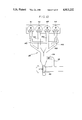
- FIG. 1A is a schematic plan view showing an exhaust device for an engine according to a first embodiment of the present invention
- FIG. 1B is a sectional view showing a part of the device in FIG. 1A;
- FIG. 2A is a schematic plan view of an exhaust device according to a second embodiment of the present invention.
- FIG. 2B is a sectional view showing a part of the device in FIG. 2A;
- FIG. 3 is a sectional view showing a part of an exhaust device according to a third embodiment of the present invention.
- FIG. 4 is a view similar to FIG. 3 showing a fourth embodiment of the present invention.
- FIG. 5 is a schematic plan view of the exhaust device according to a fifth embodiment of the present invention.
- FIG. 6 is a diagram showing the relationship between degrees of opening of primary and secondary exhaust valves relative to a crank angle
- FIGS. 7 and 8 are schematic plan views of the exhaust devices according to sixth and seventh embodiments, respectively, of the present invention.
- FIG. 9A is a schematic plan view of the exhaust device according to an eighth embodiment of the present invention.
- FIG. 9B is a sectional view showing a part of the device in FIG. 9A;
- FIG. 10 is a schematic plan view of the exhaust device according to a ninth embodiment of the present invention.
- FIGS. 11 and 12 are schematic plan views of the exhaust device according to tenth and eleventh embodiments, respectively, of the present invention.
- FIGS. 13 A and B are diagrams showing relationships of temperature of exhaust gases and fuel consumption relative to air-fuel ratio
- FIG. 14 is a schematic plan view showing a conventional exhaust device used in tests
- FIGS. 15 and 16 are schematic plan views of the exhaust devices according to twelfth and thirteenth embodiments, resepectively, of the present invention.
- FIGS. 17 A and B are diagrams each showing fuel consumption relative to diameter of a communicating passage.
- FIGS. 18 A and B are explanatory plan views of the devices used for measurement of the characteristics shown in FIG. 17.
- FIGS. 1A and 1B of the drawings there is illustrated an exhaust device of the invention applied to a four-cylinder (#1 through #4) engine having a turbocharger.
- Each cylinder includes a piston 10 mounted in a cylinder block 12 for defining a combustion chamber 23 in cooperation with a cylinder head 18.
- Formed in the cylinder head 18 are intake and exhaust ports 14 and 16 which are adapted to open to the combustion chamber 23 through intake and exhaust valves 20 and 22, respectively.
- each exhaust port 16 is connected to an exhaust passage 24 which, in the illustrated embodiment, comprises four independent passages 26, 28, 30 and 32 and a communicating passage 34.
- the independent passages are separately connected at first ends thereof to the exhaust ports 16 of the respective cylinders and are joined together at second ends so as to form a single passage 38 downstream of the junction.
- the communicating passage 34 communicates the independent passages with each other at points upstream of the junction, that is, near the exhaust ports 16 in the illustrated embodiment.
- Each independent passage of this embodiment is formed to have a diameter smaller than a diameter of the communicating passage 34.
- a rotary-type valve 36 is provided in each branch of the communicating passage 34 bifurcating from the independent passage, so that the respective communication may be controlled according to the engine conditions as described hereinafter.
- the rotational axes of the valves 36 are all aligned as seen from FIG. 1A.
- a turbine 40 adapted to be rotationally driven by the exhaust gases, and a bypass 42 is formed to have the gases bypass the turbine 40 when so desired.
- the bypass 42 is opened or closed by a waste gate valve 44 disposed therein.
- the valves 36 are opened in the high-speed, high-loaded engine conditions.
- a part of the exhaust gases from one of the cylinders #1 through #4 is directly supplied to the turbine 40 through one of the independent passages 26, 28, 30 and 32 connected to the corresponding exhaust port 16 of the cylinder.
- the other part of gases flows into the communicating passage 34 and then the other independent passages and is thereafter supplied to the turbine 40.
- the exhaust gases are discharged from the exhaust port 16 of the cylinder #1
- a part of the gases is supplied to the turbine 40 directly through the independent passage 26 for the cylinder #1, and the other part of the gases is supplied through the other independent passages 28, 30 and 32 for the cylinders #2 to #4 via the communicating passage 34.
- This increases the effective area for the flow of gases because the gases are discharged through the plural independent passages.
- valves 36 are closed or shut in the low-speed, low-loaded engine conditions.
- the exhaust gases from each of the cylinders #1 through #4 are led to the turbine 40 through only one of the independent exhaust passages 26, 28, 30 and 32 connected to the corresponding exhaust port 16.
- each independent passage to have a desired small diameter, the exhaust gases are restrained from expanding and their flow velocity is maintained until they reach the turbine 40 for providing the energy thereto. Accordingly, high dynamic charging effect can be obtained, and the torque and accelerating response at low speeds can be improved.
- boost can be controlled by the waste gate valve 44 in the bypass 42, and it is also possible to control the boost by gradually opening the valves 36 and by the waste gate valve 44 after the valves 36 are fully opened.
- a communicating passage comprises a first passage 50 which communicates the two independent passages 26 and 32 for the respective cylinders #1 and #4 with each other, and a second passage 52 which communicates the other two independent passages 28 and 30 for the respective cylinders #2 and #3 with each other.
- This structure has an additional advantage that there is no interaction between the exhaust gases discharged from the cylinders #1 through #4.
- each passage should communicate a group of independent passages in such a manner that each group exhausts alternately, to thereby prevent the interaction of exhaust gases.
- the application of the plural communicating passage structure is not limited to a four-cylinder engine.
- valves 36 provided in each branch of the communicating passages 50 and 52 in the second embodiment, a single valve may be provided in the intermediate portion of each communicating passage. In that case, the structure can be simplified.
- An exhaust device illustrated in FIG. 3 is different from the device of FIG. 1 in that a swing-arm type valve 60 is provided instead of the rotary type valve 36, which valve 60 is adapted to open or close an opening of the exhaust port 16 for controlling the communication between the independent passage 26, 28, 30 or 32 and the communicating passage 34.
- the arm type valve 60 may be more reliable than the rotary type valve.
- a communicating passage 62 is secured to each cylinder head 18 through a gasket 64 and has a double wall structure to define therebetween a space 66 in which circulates a cooling water 68 used in the cylinder head 18. This can remarkably promote the lowering of temperature and pressure of the exhaust gases to be supplied to the turbine 40.
- FIG. 5 shows another modification of the present invention applied to a so-called twin-scroll turbocharger in which independent passages 70 and 72 for cylinders #1 and #2 are joined together to form a first combined passage 82 and independent passages 74 and 76 for cylinders #3 and #4 are also joined together to form a second combined passage 84, and in which these two combined passages separately extend to the turbine 40.
- each of the cylinders #1 through #4 is provided with two exhaust valves, namely primary valve P and secondary valve S.
- the primary valve P is located closer to a branch of a communicating passage 78 and is arranged to open earlier than the secondary valve S as shown in FIG. 6.
- the high-pressure, high-temperature blowdown gases effectively flow into the communicating passage 78 by fully opening the primary valves P earlier than the secondary valves S, resulting in a greater decrease in pressure and temperature of the exhaust gases.
- each of the cylinders #1 through #4 is not individually provided with a valve, but only a single valve 80 is provided within th communicating passage 78 at a position between the two groups of the cylinders, i.e. cylinders #1 and #2 and cylinders #3 and #4, each group being connected to each combined passage so that the control mechanism is simplified without significantly impairing the response of the turbocharger.
- FIG. 7 An exhaust device in FIG. 7 is illustrated as applied to a six-cylinder (#1 through #6) engine provided with two separate turbines 86 and 88, i.e. a so-called twin turbo engine, in which the turbine 86 is arranged to be driven by the exhaust gases from independent passages 90, 92 and 94 for the cylinders #1 to #3, respectively, and the other turbine 88 is driven by exhaust gases from independent passages 96, 98 and 100 for the cylinders #4 to #6, respectively.
- a communicating passage 102 is shown as having six valves 36 mounted in six branches, these valves 36 may be replaced by a single valve mounted within the communicating passage 102 at a position between the two groups of cylinders connected to the respective turbines.
- FIG. 8 shows another modification of the invention applied to the twin scroll turbocharger as in the embodiment of FIG. 5.
- independent passages 120 and 126 for the respective cylinders #1 and #4 are combined together to form one scroll
- independent passages 122 and 124 for the respective cylinders #2 and #3 are also combined together to form another scroll.
- Two communicating passages 110 and 112 are provided, one (110) communicating the independent passages 120 and 122 with each other and the other (112) communicating the independent passages 124 and 126.
- FIGS. 5, 7 and 8 can attain the advantages of the invention without spoiling the known advantages of the twin scroll turbocharger or twin turbo engine.
- each independent passage is formed to have a smaller diameter than the communicating passage
- an exhaust device as shown in FIGS. 9A and 9B has independent passages 130, 132, 134 and 136 formed at substantially the same diameter as a communicating passage 138. This arrangement is also sufficient, particularly for the lowering of pressure and temperature of the exhaust gases in the high-speed, high-loaded engine conditions. Details about the relationship between the independent passage diameter and communicating passage diameter will be described hereinafter.
- FIG. 10 illustrates still another embodiment of the invention applied to a turbocharged engine having four cylinders, in which independent passages 140 and 146 for the respective cylinders #1 and #4 are formed to have a diameter smaller than a diameter of independent passages 142 and 144 for the cylinders #2 and #3 positioned between the cylinders #1 and #4.
- a single communicating passage 148 is provided to communicate only the two independent passages, i.e. passages 140 and 146, positioned farthest from each other.
- the exhaust gases from the cylinders #2 and #3, which are situated closer to the turbine 40 than are the cylinders #1 and #4 are, quickly supplied to the turbine 40 through their respective passages 142 and 144 so that a charging response may be maintained at a sufficient level.
- the independent passages 140 and 146 for the cylinders #1 and #4 are formed small in diameter in order to prevent expansion of the exhaust gases during the relatively long travel to the turbine 40, but the communicating passage 148 having a large length can radiate the heat to thereby lower the gas temperature.
- valves such as 36 in the above embodiments may be omitted, which can further simplify the structure.
- valve for closing the communicating passage is not essential, particularly for the purpose of improving fuel consumption in the high-speed, high-loaded engine conditions.
- the invention may also be applicable to an engine with no turbocharger, i.e. to a naturally aspirated engine, and several examples thereof will be described below.
- FIG. 11 shows one example of the present device applied to a naturally aspirated engine in which independent passages 160, 162, 164 and 166 are communicated with each other through a communicating passage 168.
- FIG. 12 shows another example of the device applied to a naturally aspirated engine in which independent passages 170 and 176 for cylinders #1 and #4, of which exhaust strokes are not continuous, are communicated by a passage 178, and the remaining independent passages 172 and 174 for cylinders #2 and #3, of which exhaust strokes also are not continuous, are communicated by another passage 179, as in the embodiment of FIG. 2.
- the temperatures (marked with black circles) in the FIG. 12 device were found to be below the limit at both Points A and B even when the air-fuel ratio was approximately 15, i.e the theoretical ratio. Accordingly, by setting a critical air-fuel ratio to be approximately 15, the fuel consumption can be improved by about 12% compared with the conventional device, as indicated in FIG. 13B.
- the FIG. 12 device was able to lower the exhaust gas temperature relative to the air-fuel ratio by an amount greater than the FIG. 11 device. This is because of the smaller amount of gasses flowing into Point A in the FIG. 12 device in which one communicating passage connects two of the four independnent passages with each other. For the same reason, the temperatures were higher at Point B than at Point A.
- FIG. 15 shows still another modification of the present invention applied to a naturally aspirated engine which, as in the FIG. 12 device, has two communicating passages 180 and 181, the passage 180 communicating two independent passages 182 and 188 for the cylinders #1 and #4 of which the exhaust strokes are not continuous, and the passage 181 communicating the other two independent passages 184 and 186 for the cylinders #2 and #3 of which the exhaust strokes similarly are not continuous.
- the pairs of the independent passages 182 and 188, and 184 and 186 are first combined to form intermediate portions 190 and 192, respectively, which are finally joined together at 194.
- the total length of the exhaust passages up to the single portion 194 can be increased by elongating only the two intermediate portions 190 and 192, to thus lower the gas temperature in the portion 194.
- This is advantageous in size and weight of the exhaust device, when compared with elongating each independent passage. Adjusting the length of the intermediate portions 190 and 192 makes it possible to substantially equalize the temperature at Point A with the temperature at Point B, thereby permitting the air-fuel ratio to be set as lean as possible for further improving the fuel consumption.
- valves need not be provided in the communicating passage for closing the same.
- the communicating passages it is particularly preferable to provide the communicating passages in such a manner that each passage communicates the independent passages for those cylinders the exhaust strokes of which substantially do not overlap, so that interaction of the exhaust gases may be prevented.
- An exhaust device shown in FIG. 16 is similar to the above device but is different therefrom in that the adjacent independent passages 184 and 186 for the cylinders #2 and #3 are not communicated with each other. Thus, only a single communicating passage 200 is provided to connect the independent passage 182 with 188, these passages 182 and 188 being situated farthest from each other. While simplifying the structure, this device may still lower the exhaust gas temperature effectively by the communicating passage 200 which necessarily has a large length through which the heat is radiated.
- FIGS. 18A and 18B In order to see how the fuel consumption varies according to a dimensional change of the communicating passage, the applicants prepared two sample devices as shown in FIGS. 18A and 18B.
- the exhaust device of FIG. 18A is substantially the same as that of FIG. 5 and was applied to a turbocharged engine (1.6 liter with four cylinders) having one exhaust valve for each cylinder, and the exhaust device of FIG. 18B had substantially the same structure as that of FIG. 12 and was applied to a naturally aspirated engine (2.0 liter with four cylinders).
- D 1 the diameter of the independent passage
- D 2 The exhaust manifold in FIG.
- the fuel consumption ratio began to decrease remarkably when D 2 was set to about one half of D 1 , and became substantially constant after D 2 approximated D 1
- the communicating passage has a diameter D 2 over one half (1/2) of the diameter D 1 of the independent passage and, more preferably, the diameter D 2 should approximate or even exceed the diameter D 1
- remarkable improvement in the fuel consumption ratio began to be observed when D 2 was about one quarter of D 1 , and became substantially constant after D 2 approximated one half of D 1 as seen from FIG. 17B.
- the communicating passage should preferably have a diameter D 2 over one quarter (1/4) of the diameter D 1 of the independent passage and, more preferably, the diameter D 2 should be more than one half (1/2) of the diameter D 1 .
- the communicating passage is branched off the independent passage preferably in such a manner that the exhaust gases, when flowing into the independent passage from the branch, flow in the upstream direction, i.e. toward the exhaust port.
- a distance between the exhaust port 16 and the opening of a communicating passage is less than one half (1/2) of a distance between the exhaust port and the first junction (L 1 ) so that the gases may flow into the communicating passage immediately after being discharged from the exhaust port.
Landscapes
- Engineering & Computer Science (AREA)
- Chemical & Material Sciences (AREA)
- Combustion & Propulsion (AREA)
- Mechanical Engineering (AREA)
- General Engineering & Computer Science (AREA)
- Supercharger (AREA)
- Exhaust Silencers (AREA)
Applications Claiming Priority (2)
| Application Number | Priority Date | Filing Date | Title |
|---|---|---|---|
| JP12374286 | 1986-05-30 | ||
| JP61-123742 | 1986-05-30 |
Publications (1)
| Publication Number | Publication Date |
|---|---|
| US4813232A true US4813232A (en) | 1989-03-21 |
Family
ID=14868203
Family Applications (1)
| Application Number | Title | Priority Date | Filing Date |
|---|---|---|---|
| US07/055,333 Expired - Lifetime US4813232A (en) | 1986-05-30 | 1987-05-28 | Exhaust device for internal combustion engine |
Country Status (4)
| Country | Link |
|---|---|
| US (1) | US4813232A (de) |
| EP (1) | EP0247631B1 (de) |
| JP (1) | JP2557060B2 (de) |
| DE (1) | DE3775986D1 (de) |
Cited By (23)
| Publication number | Priority date | Publication date | Assignee | Title |
|---|---|---|---|---|
| US4953352A (en) * | 1985-08-26 | 1990-09-04 | Campbell Monty A | Exhaust system |
| US5101626A (en) * | 1990-07-19 | 1992-04-07 | Outboard Marine Corporation | Exhaust gas discharge system for two-stroke internal combustion engine |
| US5261231A (en) * | 1991-04-02 | 1993-11-16 | Huh Chan Hoi | Intake/exhaust air pressure balancer and method of reducing intake/exhaust air pressure resistance |
| US5437155A (en) * | 1993-10-13 | 1995-08-01 | Outboard Marine Corporation | Outboard motor exhaust system |
| US5809778A (en) * | 1995-06-16 | 1998-09-22 | J. Eberspacher Gmbh & Co. | Exhaust manifold with sheet metal inlet pipes |
| US6321532B1 (en) * | 2000-03-03 | 2001-11-27 | Dwayne D. Komush | Multiple tract exhaust manifold/header |
| US6415600B1 (en) * | 1998-07-10 | 2002-07-09 | Saab Automobile Ab | Catalytic converter system for i.c.-engine with divided flow and two converters |
| US20060037592A1 (en) * | 2004-08-19 | 2006-02-23 | Perkins Engines Company Limited | Exhaust manifold arrangement |
| US7363761B1 (en) * | 2006-10-31 | 2008-04-29 | International Engine Intellectual Property Company, Llc | Exhaust gas throttle for divided turbine housing turbocharger |
| US20080168967A1 (en) * | 2007-01-15 | 2008-07-17 | Yamaha Hatsudoki Kabushiki Kaisha | Four cycle internal combustion engine and vehicle |
| US20100011764A1 (en) * | 2008-07-16 | 2010-01-21 | Borgwarner Inc. | Thermatically operated bypass valve for passive warmup control of aftertreatment device |
| US20100095671A1 (en) * | 2007-02-07 | 2010-04-22 | Hajime Takagawa | Cylinder head of internal-combustion engine |
| US20100126153A1 (en) * | 2006-08-09 | 2010-05-27 | Hiroki Nagafuchi | Internal combustion engine |
| US20100206265A1 (en) * | 2009-02-13 | 2010-08-19 | Mazda Motor Corporation | Exhaust passage structure of multi-cylinder engine |
| US8065878B2 (en) | 2008-03-10 | 2011-11-29 | Deere & Company | Two phase exhaust for internal combustion engine |
| US20120210712A1 (en) * | 2011-02-17 | 2012-08-23 | GM Global Technology Operations LLC | Secondary air injection system and method |
| US20130199466A1 (en) * | 2012-02-08 | 2013-08-08 | Ford Global Technologies, Llc | Multi-cylinder internal combustion engine and method for operating a multi-cylinder internal combustion engine of said type |
| US20150052882A1 (en) * | 2012-04-05 | 2015-02-26 | Universitaet Stuttgart | Exhaust gas system for an internal combustion engine |
| US8966896B2 (en) | 2011-07-19 | 2015-03-03 | GM Global Technology Operations LLC | Secondary air injection system and method |
| CN105673172A (zh) * | 2014-12-09 | 2016-06-15 | 现代自动车株式会社 | 用于排出车辆的废气的装置 |
| DE102013205036B4 (de) | 2012-03-30 | 2019-01-17 | Honda Motor Co., Ltd. | Abgasvorrichtung für Verbrennungsmotor |
| US10400697B2 (en) * | 2015-09-30 | 2019-09-03 | Mazda Motor Corporation | Control apparatus of engine |
| US20200256242A1 (en) * | 2015-12-02 | 2020-08-13 | Borgwarner Inc. | Divided exhaust boost turbocharger |
Families Citing this family (16)
| Publication number | Priority date | Publication date | Assignee | Title |
|---|---|---|---|---|
| GB8719983D0 (en) * | 1987-08-25 | 1987-09-30 | Hansen P G | Exhaust for ic engine |
| JP2687549B2 (ja) * | 1989-03-01 | 1997-12-08 | スズキ株式会社 | 四サイクル四気筒エンジンの排気装置 |
| FR2649756B1 (fr) * | 1989-07-12 | 1994-05-27 | Peugeot | Dispositif d'echappement perfectionne pour un moteur muni d'un turbocompresseur, notamment pour vehicule automobile |
| GB2295647A (en) * | 1994-12-02 | 1996-06-05 | Ford Motor Co | Engine exhaust manifold system |
| GB2302366A (en) * | 1995-06-21 | 1997-01-15 | Ford Motor Co | I.c.engine exhaust manifold |
| US6892532B2 (en) * | 2002-05-31 | 2005-05-17 | Caterpillar Inc | Exhaust system having low-stress exhaust manifold flange |
| FR2857697B1 (fr) * | 2003-07-15 | 2006-01-21 | Inst Francais Du Petrole | Moteur a combustion interne a quatre temps suralimente avec dispositif d'echappement des gaz d'echappement a volume variable et procede de fonctionnement d'un tel moteur |
| JP4667332B2 (ja) * | 2006-09-06 | 2011-04-13 | 川崎重工業株式会社 | 小型滑走艇 |
| DE102006042464A1 (de) * | 2006-09-09 | 2008-03-27 | Audi Ag | Verbrennungsmotor mit Abgasturboladeranordnung und Verfahren zum Betreiben eines Verbrennungsmotors und Abgasturboladeranordnung |
| WO2009143883A1 (en) * | 2008-05-27 | 2009-12-03 | Abb Turbo Systems Ag | Exhaust system |
| JP5845699B2 (ja) * | 2011-08-04 | 2016-01-20 | マツダ株式会社 | 多気筒エンジンの排気装置 |
| US9068501B2 (en) | 2013-02-01 | 2015-06-30 | Ford Global Technologies, Llc | Branch communication valve for a twin scroll turbocharger |
| US9482148B2 (en) | 2013-11-06 | 2016-11-01 | Ford Global Technologies, Llc | Active exhaust pulse management |
| DE102017220191A1 (de) | 2017-11-14 | 2019-05-16 | Bayerische Motoren Werke Aktiengesellschaft | Brennkraftmaschine und Verfahren zum Betreiben der Brennkraftmaschine |
| DE102017220192A1 (de) | 2017-11-14 | 2019-05-16 | Bayerische Motoren Werke Aktiengesellschaft | Brennkraftmaschine und Verfahren zum Betreiben der Brennkraftmaschine |
| DE102018215119B3 (de) * | 2018-09-06 | 2019-11-28 | Bayerische Motoren Werke Aktiengesellschaft | V8-Cross-Plane-Brennkraftmaschine und Betriebsverfahren |
Citations (7)
| Publication number | Priority date | Publication date | Assignee | Title |
|---|---|---|---|---|
| FR1140745A (fr) * | 1955-02-03 | 1957-08-12 | Maschf Augsburg Nuernberg Ag | Tuyauterie d'échappement pour moteurs polycylindriques à deux temps et lumières de distribution, combinés avec des turbines de suralimentation entraînées par les gaz d'échappement |
| GB955056A (en) * | 1962-01-05 | 1964-04-08 | Panhard & Levassor | Improvements in exhaust systems for internal combustion engines |
| FR2122131A5 (de) * | 1971-01-12 | 1972-08-25 | Bosch | |
| DE2852736A1 (de) * | 1978-12-06 | 1980-06-19 | Daimler Benz Ag | An einer mehrzylindrigen brennkraftmaschine angeordnete abgasanlage |
| JPS59523A (ja) * | 1982-06-23 | 1984-01-05 | Suzuki Motor Co Ltd | 多気筒エンジンの排気装置 |
| JPS5968520A (ja) * | 1982-10-12 | 1984-04-18 | Yamaha Motor Co Ltd | 多気筒内燃機関の排気装置 |
| JPS59148427A (ja) * | 1983-02-14 | 1984-08-25 | Central Res Inst Of Electric Power Ind | サイリスタ模擬回路 |
Family Cites Families (4)
| Publication number | Priority date | Publication date | Assignee | Title |
|---|---|---|---|---|
| JPS57167223U (de) * | 1981-04-16 | 1982-10-21 | ||
| JPS60190930U (ja) * | 1984-05-29 | 1985-12-18 | カルソニックカンセイ株式会社 | 自動車用排気系に於けるデユアルタイプのフロントチユ−ブ |
| JPS6238414U (de) * | 1985-08-26 | 1987-03-07 | ||
| DE3602615C1 (de) * | 1986-01-29 | 1987-08-06 | Audi Ag | Mehrzylinder-Brennkraftmaschine mit Abgasturbolader |
-
1987
- 1987-05-28 JP JP62130002A patent/JP2557060B2/ja not_active Expired - Lifetime
- 1987-05-28 US US07/055,333 patent/US4813232A/en not_active Expired - Lifetime
- 1987-05-29 EP EP87107837A patent/EP0247631B1/de not_active Expired - Lifetime
- 1987-05-29 DE DE8787107837T patent/DE3775986D1/de not_active Expired - Fee Related
Patent Citations (7)
| Publication number | Priority date | Publication date | Assignee | Title |
|---|---|---|---|---|
| FR1140745A (fr) * | 1955-02-03 | 1957-08-12 | Maschf Augsburg Nuernberg Ag | Tuyauterie d'échappement pour moteurs polycylindriques à deux temps et lumières de distribution, combinés avec des turbines de suralimentation entraînées par les gaz d'échappement |
| GB955056A (en) * | 1962-01-05 | 1964-04-08 | Panhard & Levassor | Improvements in exhaust systems for internal combustion engines |
| FR2122131A5 (de) * | 1971-01-12 | 1972-08-25 | Bosch | |
| DE2852736A1 (de) * | 1978-12-06 | 1980-06-19 | Daimler Benz Ag | An einer mehrzylindrigen brennkraftmaschine angeordnete abgasanlage |
| JPS59523A (ja) * | 1982-06-23 | 1984-01-05 | Suzuki Motor Co Ltd | 多気筒エンジンの排気装置 |
| JPS5968520A (ja) * | 1982-10-12 | 1984-04-18 | Yamaha Motor Co Ltd | 多気筒内燃機関の排気装置 |
| JPS59148427A (ja) * | 1983-02-14 | 1984-08-25 | Central Res Inst Of Electric Power Ind | サイリスタ模擬回路 |
Cited By (34)
| Publication number | Priority date | Publication date | Assignee | Title |
|---|---|---|---|---|
| US4953352A (en) * | 1985-08-26 | 1990-09-04 | Campbell Monty A | Exhaust system |
| US5101626A (en) * | 1990-07-19 | 1992-04-07 | Outboard Marine Corporation | Exhaust gas discharge system for two-stroke internal combustion engine |
| USRE34764E (en) * | 1990-07-19 | 1994-10-25 | Outboard Marine Corporation | Exhaust gas discharge system for two-stroke internal combustion engine |
| US5261231A (en) * | 1991-04-02 | 1993-11-16 | Huh Chan Hoi | Intake/exhaust air pressure balancer and method of reducing intake/exhaust air pressure resistance |
| US5437155A (en) * | 1993-10-13 | 1995-08-01 | Outboard Marine Corporation | Outboard motor exhaust system |
| US5809778A (en) * | 1995-06-16 | 1998-09-22 | J. Eberspacher Gmbh & Co. | Exhaust manifold with sheet metal inlet pipes |
| US6415600B1 (en) * | 1998-07-10 | 2002-07-09 | Saab Automobile Ab | Catalytic converter system for i.c.-engine with divided flow and two converters |
| US6321532B1 (en) * | 2000-03-03 | 2001-11-27 | Dwayne D. Komush | Multiple tract exhaust manifold/header |
| US20060037592A1 (en) * | 2004-08-19 | 2006-02-23 | Perkins Engines Company Limited | Exhaust manifold arrangement |
| US7150273B2 (en) | 2004-08-19 | 2006-12-19 | Perkins Engines Company Limited | Exhaust manifold arrangement |
| US20100126153A1 (en) * | 2006-08-09 | 2010-05-27 | Hiroki Nagafuchi | Internal combustion engine |
| US7363761B1 (en) * | 2006-10-31 | 2008-04-29 | International Engine Intellectual Property Company, Llc | Exhaust gas throttle for divided turbine housing turbocharger |
| US20080098733A1 (en) * | 2006-10-31 | 2008-05-01 | International Engine Intellectual Property Company, Llc | Exhaust gas throttle for divided turbine housing turbocharger |
| US20080168967A1 (en) * | 2007-01-15 | 2008-07-17 | Yamaha Hatsudoki Kabushiki Kaisha | Four cycle internal combustion engine and vehicle |
| US7556028B2 (en) * | 2007-01-15 | 2009-07-07 | Yamaha Hatsudoki Kabushiki Kaisha | Four cycle internal combustion engine and vehicle |
| US20100095671A1 (en) * | 2007-02-07 | 2010-04-22 | Hajime Takagawa | Cylinder head of internal-combustion engine |
| US8209980B2 (en) * | 2007-02-07 | 2012-07-03 | Toyota Jidosha Kabushiki Kaisha | Cylinder head of internal-combustion engine |
| US8065878B2 (en) | 2008-03-10 | 2011-11-29 | Deere & Company | Two phase exhaust for internal combustion engine |
| US20100011764A1 (en) * | 2008-07-16 | 2010-01-21 | Borgwarner Inc. | Thermatically operated bypass valve for passive warmup control of aftertreatment device |
| US8234865B2 (en) * | 2008-07-16 | 2012-08-07 | Borgwarner Inc. | Thermatically operated bypass valve for passive warmup control of aftertreatment device |
| US8256402B2 (en) * | 2009-02-13 | 2012-09-04 | Mazda Motor Corporation | Exhaust passage structure of multi-cylinder engine |
| US20100206265A1 (en) * | 2009-02-13 | 2010-08-19 | Mazda Motor Corporation | Exhaust passage structure of multi-cylinder engine |
| US20120210712A1 (en) * | 2011-02-17 | 2012-08-23 | GM Global Technology Operations LLC | Secondary air injection system and method |
| US8806868B2 (en) * | 2011-02-17 | 2014-08-19 | GM Global Technology Operations LLC | Secondary air injection system and method |
| US8966896B2 (en) | 2011-07-19 | 2015-03-03 | GM Global Technology Operations LLC | Secondary air injection system and method |
| US20130199466A1 (en) * | 2012-02-08 | 2013-08-08 | Ford Global Technologies, Llc | Multi-cylinder internal combustion engine and method for operating a multi-cylinder internal combustion engine of said type |
| DE102013205036B4 (de) | 2012-03-30 | 2019-01-17 | Honda Motor Co., Ltd. | Abgasvorrichtung für Verbrennungsmotor |
| US20150052882A1 (en) * | 2012-04-05 | 2015-02-26 | Universitaet Stuttgart | Exhaust gas system for an internal combustion engine |
| US9267418B2 (en) * | 2012-04-05 | 2016-02-23 | Universitaet Stuttgart | Exhaust gas system for an internal combustion engine |
| CN105673172A (zh) * | 2014-12-09 | 2016-06-15 | 现代自动车株式会社 | 用于排出车辆的废气的装置 |
| US9664099B2 (en) * | 2014-12-09 | 2017-05-30 | Hyundai Motor Company | Apparatus for discharging exhaust gas of vehicle |
| CN105673172B (zh) * | 2014-12-09 | 2019-08-30 | 现代自动车株式会社 | 用于排出车辆的废气的装置 |
| US10400697B2 (en) * | 2015-09-30 | 2019-09-03 | Mazda Motor Corporation | Control apparatus of engine |
| US20200256242A1 (en) * | 2015-12-02 | 2020-08-13 | Borgwarner Inc. | Divided exhaust boost turbocharger |
Also Published As
| Publication number | Publication date |
|---|---|
| DE3775986D1 (de) | 1992-02-27 |
| EP0247631B1 (de) | 1992-01-15 |
| JPS63106319A (ja) | 1988-05-11 |
| EP0247631A1 (de) | 1987-12-02 |
| JP2557060B2 (ja) | 1996-11-27 |
Similar Documents
| Publication | Publication Date | Title |
|---|---|---|
| US4813232A (en) | Exhaust device for internal combustion engine | |
| US6595183B1 (en) | Internal combustion engine | |
| US5203311A (en) | Exhaust gas recirculation system for an internal combustion engine | |
| US8256402B2 (en) | Exhaust passage structure of multi-cylinder engine | |
| US4488531A (en) | Plural intake system for supercharged engine | |
| JP4032398B2 (ja) | ターボ過給機付エンジン及びターボ過給機付エンジン搭載車のパワーユニット | |
| JP2002527673A (ja) | 内燃機関 | |
| JPS61210224A (ja) | 排気タ−ボ過給機付エンジン | |
| EP0469596B1 (de) | Mehrzylinder Zweitakt-Brennkraftmaschine | |
| US4781154A (en) | Two-cycle internal combustion engine | |
| CN112780404A (zh) | 一种大功率v型船用柴油机单排补气装置及补气方法 | |
| US4912930A (en) | High performance exhaust system for internal combustion engine | |
| EP0278032B1 (de) | Hochleistungsauspuffanlage für Brennkraftmaschine | |
| JPS59147823A (ja) | 排気タ−ボ過給4サイクル機関 | |
| JPS59692B2 (ja) | 排気タ−ボ過給機関 | |
| JP2022136515A (ja) | エンジン | |
| JPH05340290A (ja) | 過給機付エンジンの制御装置 | |
| JPH0717787Y2 (ja) | 過給機付エンジン | |
| EP0046156B1 (de) | Aufgeladene Verbrennungsmaschine mit Abgas-Rückführung unter Druck | |
| JP2022136516A (ja) | エンジン | |
| JPS63192914A (ja) | エンジンの過給装置 | |
| JPS61234226A (ja) | 過給機付エンジンの吸気装置 | |
| JPS61192822A (ja) | 過給機付可変気筒式内燃機関 | |
| JPH01117923A (ja) | 過給機付エンジンの排気装置 | |
| JPH0567769B2 (de) |
Legal Events
| Date | Code | Title | Description |
|---|---|---|---|
| AS | Assignment |
Owner name: MAZDA MOTOR CORPORATION, 3-1, SHINCHI, FUCHU-CHO, Free format text: ASSIGNMENT OF ASSIGNORS INTEREST.;ASSIGNORS:HITOMI, MITSUO;HINATASE, FUMIO;UMEZONO, KAZUAKI;REEL/FRAME:004716/0593 Effective date: 19870423 |
|
| STCF | Information on status: patent grant |
Free format text: PATENTED CASE |
|
| FEPP | Fee payment procedure |
Free format text: PAYOR NUMBER ASSIGNED (ORIGINAL EVENT CODE: ASPN); ENTITY STATUS OF PATENT OWNER: LARGE ENTITY |
|
| FPAY | Fee payment |
Year of fee payment: 4 |
|
| FEPP | Fee payment procedure |
Free format text: PAYOR NUMBER ASSIGNED (ORIGINAL EVENT CODE: ASPN); ENTITY STATUS OF PATENT OWNER: LARGE ENTITY Free format text: PAYER NUMBER DE-ASSIGNED (ORIGINAL EVENT CODE: RMPN); ENTITY STATUS OF PATENT OWNER: LARGE ENTITY |
|
| FPAY | Fee payment |
Year of fee payment: 8 |
|
| FPAY | Fee payment |
Year of fee payment: 12 |