US4538565A - Lubricant passage system for internal combustion engines - Google Patents
Lubricant passage system for internal combustion engines Download PDFInfo
- Publication number
- US4538565A US4538565A US06/553,860 US55386083A US4538565A US 4538565 A US4538565 A US 4538565A US 55386083 A US55386083 A US 55386083A US 4538565 A US4538565 A US 4538565A
- Authority
- US
- United States
- Prior art keywords
- oil
- gallery
- side wall
- crankshaft
- oil filter
- Prior art date
- Legal status (The legal status is an assumption and is not a legal conclusion. Google has not performed a legal analysis and makes no representation as to the accuracy of the status listed.)
- Expired - Lifetime
Links
Images


Classifications
-
- F—MECHANICAL ENGINEERING; LIGHTING; HEATING; WEAPONS; BLASTING
- F01—MACHINES OR ENGINES IN GENERAL; ENGINE PLANTS IN GENERAL; STEAM ENGINES
- F01M—LUBRICATING OF MACHINES OR ENGINES IN GENERAL; LUBRICATING INTERNAL COMBUSTION ENGINES; CRANKCASE VENTILATING
- F01M11/00—Component parts, details or accessories, not provided for in, or of interest apart from, groups F01M1/00 - F01M9/00
-
- F—MECHANICAL ENGINEERING; LIGHTING; HEATING; WEAPONS; BLASTING
- F01—MACHINES OR ENGINES IN GENERAL; ENGINE PLANTS IN GENERAL; STEAM ENGINES
- F01M—LUBRICATING OF MACHINES OR ENGINES IN GENERAL; LUBRICATING INTERNAL COMBUSTION ENGINES; CRANKCASE VENTILATING
- F01M1/00—Pressure lubrication
- F01M1/02—Pressure lubrication using lubricating pumps
-
- F—MECHANICAL ENGINEERING; LIGHTING; HEATING; WEAPONS; BLASTING
- F01—MACHINES OR ENGINES IN GENERAL; ENGINE PLANTS IN GENERAL; STEAM ENGINES
- F01M—LUBRICATING OF MACHINES OR ENGINES IN GENERAL; LUBRICATING INTERNAL COMBUSTION ENGINES; CRANKCASE VENTILATING
- F01M1/00—Pressure lubrication
- F01M1/10—Lubricating systems characterised by the provision therein of lubricant venting or purifying means, e.g. of filters
-
- F—MECHANICAL ENGINEERING; LIGHTING; HEATING; WEAPONS; BLASTING
- F01—MACHINES OR ENGINES IN GENERAL; ENGINE PLANTS IN GENERAL; STEAM ENGINES
- F01M—LUBRICATING OF MACHINES OR ENGINES IN GENERAL; LUBRICATING INTERNAL COMBUSTION ENGINES; CRANKCASE VENTILATING
- F01M11/00—Component parts, details or accessories, not provided for in, or of interest apart from, groups F01M1/00 - F01M9/00
- F01M11/02—Arrangements of lubricant conduits
-
- F—MECHANICAL ENGINEERING; LIGHTING; HEATING; WEAPONS; BLASTING
- F01—MACHINES OR ENGINES IN GENERAL; ENGINE PLANTS IN GENERAL; STEAM ENGINES
- F01M—LUBRICATING OF MACHINES OR ENGINES IN GENERAL; LUBRICATING INTERNAL COMBUSTION ENGINES; CRANKCASE VENTILATING
- F01M11/00—Component parts, details or accessories, not provided for in, or of interest apart from, groups F01M1/00 - F01M9/00
- F01M11/03—Mounting or connecting of lubricant purifying means relative to the machine or engine; Details of lubricant purifying means
Definitions
- the present invention relates to a lubricant passage system for lubricating portions of an internal combustion engine such as the bearing portions of the crankshaft or the bearing portions of a valve actuating mechanism.
- the engine body is equipped with a lubricating oil pump and an oil filter and is formed in itself with an oil gallery so that a lubricant pumped by the oil pump is fed, after it has been filtered by the action of the oil filter, by way of the oil gallery to a plurality of branched oil supply passages. In this way lubricant is supplied to those portions to be lubricated.
- the oil gallery formed in the engine body generally has its shape complicated to raise the production cost of the engine itself.
- the present invention has been conceived in view of that background and has a principal object to provide a lubricant passage system for an internal combustion engine in which both a sub-gallery for providing communication between the discharge port of an oil pump and the inlet of an oil filter, and a main gallery for providing communication between the outlet of the oil filter and a plurality of branched oil supply passages are formed in the side wall of the engine body.
- the sub-gallery and the main gallery are generally in a straight form in parallel with the crankhaft and have their shapes so simplified that they can be easily formed, and so that their strengths may be increased without causing any increase in the weight of the engine body.
- a lubricant passage system for an internal combustion engine is constructed in a manner so that the engine body is equipped with a lubricating oil pump on the outer face of its end wall normal to a crankshaft, and having an oil filter on the outer face of its side wall parallel to said crankshaft.
- Said side wall of said engine body is formed generally in parallel with said crankshaft with both a straight sub-gallery for providing communication with the discharge port of said oil pump and the inlet of said oil filter, and a straight main gallery having communication with the output of said oil filter.
- the main gallery is made to communication with a plurality of branched oil supply passages which extend to the portions of the engine to be lubricated.
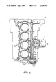
- FIG. 1 is a sectional plan view showing a preferred embodiment of this invention.
- FIG. 2 is a sectional detail partly broken away, taken substantially on the lines II--II as shown on FIG. 1.
- FIG. 3 is a transverse sectional view taken substantially on the lines III--III as shown on FIG. 1.
- FIG. 4 is a side elevation taken substantially on the lines IV--IV as shown on FIG. 1.
- FIG. 5 is a sectional view partly broken away, taken substantially on the lines V--V as shown on FIG. 3.
- FIG. 6 is a sectional detail taken substantially on the lines VI--VI as shown on FIG. 1.
- a lubricant passage system for lubricating parts within an engine body E is schematically described with reference to FIG. 1.
- a lubricating oil pump P to be driven by a crankshaft 1 is secured to an end face of the body E of a four-cylinder internal combustion engine which is normal to the direction of the crankshaft 1.
- Lubricating oil within an oil pan is pumped from that oil pump P to a sub-gallery 3 which is formed in the engine body E.
- an oil filter F To the side face of the engine body E there is secured an oil filter F.
- the lubricating oil pumped through the sub-gallery 3 passes through the oil filter and then to the main gallery 2 which is formed in the engine body E.
- the lubricating oil is then shunted from the main gallery 2 into branched oil supply passages, from which it is supplied to the parts to be lubricated, such as the bearing of the crankshaft or the valve actuating cam shaft, or both.
- the oil pump P is mounted on the outer face of an end wall 4 of the engine body E, which is normal to the crankshaft direction, so as to facilitate its drive from the crankshaft 1.
- the end wall 4 of the engine body E has its outer face formed with a mounting seat 5, to which a pump case 6 is fastened by means of a plurality of mounting bolts 7.
- a pump shaft 8 which is in parallel with the crankshaft 1 and by which inner and outer rotors 10 and 11 received in a recess 9 formed in the engine body E are driven.
- the oil pump P has its suction port 14 communicating with a suction passage 15 which is formed in the engine body E.
- a suction pipe 16 To this suction passage 15, as shown in FIG. 3, there is connected the upper end of a suction pipe 16, which has its lower end communicating with an oil reservoir 19 within an oil pan 18 by way of an oil strainer 17.
- the oil pump P has its discharge port 20 communicating with the sub-gallery 3 which is formed in the engine body E.
- the sub-gallery 3 is so formed generally in a straight rib extending on the side wall 21 of the engine body E in the crankshaft direction.
- the sub-gallery 3 extends midway of the engine body E and its inner end, i.e., its outlet port 22 is opened in the outer face of the side wall 21.
- the side wall 21 is formed adjacent the main gallery 2 which also extends in the form of a rib-shaped land generally in parallel with the sub-gallery 3.
- the main gallery 2 thus formed is opened in both the end walls of the engine body E, which are normal to the crankshaft 1, and has both its open ends plugged by means of blind plugs 23 and 24.
- the engine body E is formed at an intermediate portion of the side wall 21 in the axial direction of the crankshaft 1 with a mounting seat 25 for the oil filter F. As shown in FIG. 4, there are opened in the mounting seat both the outlet port 22 of the sub-gallery 3 and an inlet port 26 which has communication with the central portion of the main gallery 2. Thus, the lubricating oil from the sub-gallery 3 is supplied through the inlet port 26 to the main gallery 2 after it has been filtered through the oil filter F.
- FIGS. 3 and 5 there is fastened to the mounting seat 25 by means of a plurality of mounting bolts 28 a mounting base 27 having a mounting face, in which the oil filter F is threaded through a sealing member 29.
- the mounting base 27 is formed with an inlet passage 30, which leads to the outlet port 22 of the sub-gallery 3, and an annular passage 31 which has communication with the inlet passage 30. That annular passage 31 opens into the mounting base 27 and has communication with the inlet 32 of the oil filter F.
- This oil filter F has its outlet 33 communicating with the inlet port 26 of the aforementioned main gallery 2 by way of an outlet passage 34 which is formed in the mounting base 27.
- a cylindrical filter element 35 Within the oil filter F there is accommodated a cylindrical filter element 35.
- An unclean chamber a which is formed outside of that element 35, is made to have communication with the inlet passage 30 through the annular passage 31, and a clean chamber b, which is formed inside of the filter element 35, is made to communicate with the outlet passage 34.
- the lubricating oil from the outlet port 22 of the sub-gallery 3 flows through the inlet passage 30 and the annular passage 31 into the unclean chamber a of the oil filter F, and is there filtered through the filter element 35. After that, the lubricating oil flows into the clean chamber b, from which it further flows through the outlet passage 34 and the inlet port 26 into the main gallery 2.
- Mounting base 27 is equipped, as shown in FIG. 5, with a regulator R for regulating the pressure of the lubricating oil. More specifically, the mounting base 27 is provided with a bypass passage 36 which has communication with the inlet passage 30 and which opens into the crankcase 37 (FIG. 3). In the bypass passage 36, there is slidably fitted a piston-shaped valve member 38 for controlling the size of the opening of that bypass passage 36. A valve spring 39 is placed under compression between that valve member 38 and the inner wall of the mounting base so that the valve member 38 is retracted against the elastic force of the valve spring 39 to open the bypass passage 36 when the pressure of the lubricating oil flowing through the inlet passage 30 exceeds a predetermined value. Thus, the lubricating oil is returned through that bypass passage 36 to the crankcase 37, i.e., the oil pan 18.
- the main gallery 2 is made to communicate with a plurality of lower branched oil supply passages 40 which are formed in the engine body E at longitudinally spaced locations.
- the lower branched oil supply passages 40 thus formed open through crank journal walls 42 in the bearing face of the crankshaft 1.
- the central portion of the main gallery 2 communicates with an upper branched oil supply passage 41 which is provided in the engine body E and which delivers oil to the valve actuating mechanism (not shown) above the engine body E.
- the oil pump P When the internal combustion engine is operating, the oil pump P is driven by the rotations of the crankshaft 1 through the transmission belt 13 and the pulley 12.
- the lubricating oil in the oil pan 18 is primarily filtered by the oil strainer 17, and is then sucked up through the suction pipe 16 and is pumped out of the discharge port 20 to the sub-gallery 3 in the engine body E.
- the lubricating oil under pressure through the sub-gallery 3 flows from the outlet port 22 through the inlet passage 30 and the annular passage 31 of the mounting base 27 into the oil filter F.
- the lubricating oil in said filter F is secondarily filtered from the unclean chamber a through the filter element 35 until it flows through the clean chamber b at the inner side from the outlet 33.
- the clean lubricating oil in the main gallery 2 is shunted to the right and left by the inlet port 26 of the main gallery 2.
- the lubricating oil passes through the branched oil supply passages 40 to the bearing faces of the crankshaft 1, and through the upper branched oil supply passage 41 to the bearing faces of the valve actuating cam shaft of the valve actuating mechanism.
- the regulator R which is disposed in the bypass passage 36 and communicates with the inlet passage of the mounting base 27, is opened, as above.
- the valve member 38 is retracted to short-circuit the inlet passage 30 through the bypass passage 36 into the crankcase 37 (FIG. 3).
- the flow system of the lubricating oil is made to communicate with the oil reservoir 19 in the crankcase 37, thereby to make it impossible to increase the pressure of the lubricating oil in said flow system above a predetermined level.
- the side wall of the engine body in the crankshaft direction is formed generally in parallel with the crankshaft with both the straight sub-gallery for providing communication with the discharge port of the oil pump and the inlet of the oil filter and the straight main gallery having communication with the outlet of the oil filter.
- those galleries have their passage shapes so remarkably simplified as to reduce manufacturing costs.
- the plural branched oil supply passages, which are branched from the main gallery and opened in the respective portions to be lubricated, can also be formed with marked ease. Thus, it is possible to reduce the production cost for the engine body itself.
- the main gallery and the sub-gallery are formed in the side wall of the engine body, moreover, said side wall can have its strength enhanced, notwithstanding that it is relatively thin, while providing little increase in the weight of the engine body.
- the oil filter is mounted below the engine body by arranging the sub-gallery below the main gallery so that its clearance from the intake manifold, which is arranged just above said oil filter, can be substantially retained to improve the maintainability of the oil filter. Because of the close arrangements of the main gallery and the sub-gallery, moreover, it is possible to simplify the shapes of both the mounting seat of the oil filter and the lubricating oil passage formed in the mounting seat.
Applications Claiming Priority (2)
| Application Number | Priority Date | Filing Date | Title |
|---|---|---|---|
| JP57-205822 | 1982-11-24 | ||
| JP57205822A JPS5996410A (ja) | 1982-11-24 | 1982-11-24 | 内燃機関の潤滑油の通路装置 |
Publications (1)
| Publication Number | Publication Date |
|---|---|
| US4538565A true US4538565A (en) | 1985-09-03 |
Family
ID=16513272
Family Applications (1)
| Application Number | Title | Priority Date | Filing Date |
|---|---|---|---|
| US06/553,860 Expired - Lifetime US4538565A (en) | 1982-11-24 | 1983-11-18 | Lubricant passage system for internal combustion engines |
Country Status (5)
| Country | Link |
|---|---|
| US (1) | US4538565A (de) |
| JP (1) | JPS5996410A (de) |
| DE (1) | DE3342516A1 (de) |
| FR (1) | FR2536458B1 (de) |
| GB (1) | GB2130653B (de) |
Cited By (13)
| Publication number | Priority date | Publication date | Assignee | Title |
|---|---|---|---|---|
| US4702204A (en) * | 1984-12-14 | 1987-10-27 | Honda Giken Kogyo Kabuhiki Kaisha | Lubrication oil passage arrangement for water-cooled internal combustion engines |
| US4773366A (en) * | 1984-12-08 | 1988-09-27 | Bayerische Motoren Werke Aktiengesellschaft | Non-foaming crankcase configuration for piston internal-combustion engines |
| US4854276A (en) * | 1986-11-11 | 1989-08-08 | Elsbett L | Internal combustion engine with combined cooling and lubricating system |
| US4922871A (en) * | 1988-08-13 | 1990-05-08 | Dr. Ing. H.C.F. Porsche Ag | Arrangement for the purification of lubricating oil |
| US5078106A (en) * | 1989-09-26 | 1992-01-07 | Nissan Motor Co., Ltd. | V-type engine lubrication system |
| US5842451A (en) * | 1996-11-15 | 1998-12-01 | Daimler-Benz Ag | Camshaft drive housing for an internal combustion engine |
| US5887565A (en) * | 1997-01-17 | 1999-03-30 | Suzuki Motor Corporation | Lubricating oil passage structure for engine |
| US6016784A (en) * | 1997-01-31 | 2000-01-25 | Suzuki Motor Corporation | Oil filter attaching structure for engine |
| US6554104B2 (en) * | 2000-03-31 | 2003-04-29 | Honda Giken Kogyo Kabushiki Kaisha | Lubrication structure for internal combustion engine |
| US20040104074A1 (en) * | 2002-09-11 | 2004-06-03 | Kazuyuki Nakai | Lubricating device for engine |
| US20100133164A1 (en) * | 2008-04-17 | 2010-06-03 | Toyota Jidosha Kabushiki Kaisha | Oil strainer |
| US20180179927A1 (en) * | 2016-12-28 | 2018-06-28 | Kubota Corporation | Engine |
| WO2024073186A1 (en) * | 2022-09-30 | 2024-04-04 | Filtran Llc | Filter assembly |
Families Citing this family (6)
| Publication number | Priority date | Publication date | Assignee | Title |
|---|---|---|---|---|
| JPS60155710U (ja) * | 1984-03-27 | 1985-10-17 | 本田技研工業株式会社 | 内燃機関における潤滑装置 |
| JPS61125615U (de) * | 1985-01-25 | 1986-08-07 | ||
| JPH0614005Y2 (ja) * | 1987-03-12 | 1994-04-13 | トヨタ自動車株式会社 | エンジンの潤滑装置 |
| JPH0814246B2 (ja) * | 1987-03-31 | 1996-02-14 | 本田技研工業株式会社 | エンジンの潤滑油通路の構造 |
| GB9010685D0 (en) * | 1990-05-12 | 1990-07-04 | Concentric Pumps Ltd | I.c.engines |
| JP3326842B2 (ja) * | 1993-02-10 | 2002-09-24 | スズキ株式会社 | スクータのオイル濾過装置 |
Citations (6)
| Publication number | Priority date | Publication date | Assignee | Title |
|---|---|---|---|---|
| US2118283A (en) * | 1929-01-30 | 1938-05-24 | Catherine B Winslow | Lubricating system for internal combustion engines |
| US2963006A (en) * | 1957-07-12 | 1960-12-06 | Harnischfeger Corp | Two cycle super charged internal combustion engine |
| US3127586A (en) * | 1962-06-01 | 1964-03-31 | Chrysler Corp | Lubrication warning signal |
| US3949725A (en) * | 1974-03-11 | 1976-04-13 | Ateliers De La Motobecane | Improvements made to the lubrication of engines |
| US3961614A (en) * | 1973-10-11 | 1976-06-08 | Regie Nationale Des Usines Renault | Lubricating system for internal combustion engines |
| US3973548A (en) * | 1975-05-29 | 1976-08-10 | Aldo Celli | Engine with die cast static parts |
Family Cites Families (7)
| Publication number | Priority date | Publication date | Assignee | Title |
|---|---|---|---|---|
| US3094190A (en) * | 1960-06-08 | 1963-06-18 | Gen Motors Corp | Internal combustion engine |
| DE2456524A1 (de) * | 1974-11-29 | 1976-08-12 | Kloeckner Humboldt Deutz Ag | Druckumlaufschmieroelanlage fuer brennkraftmaschinen |
| DE2524272A1 (de) * | 1975-05-31 | 1976-12-09 | Daimler Benz Ag | Trockensumpfschmierung fuer eine brennkraftmaschine |
| US4174699A (en) * | 1977-12-27 | 1979-11-20 | General Motors Corporation | Engine oil processing system |
| US4213441A (en) * | 1978-10-16 | 1980-07-22 | General Motors Corporation | Engine with wall rib oil gauge mounting and drain means |
| US4237847A (en) * | 1979-03-21 | 1980-12-09 | Cummins Engine Company, Inc. | Composite engine block having high strength to weight ratio |
| JPS5516090U (de) * | 1979-08-13 | 1980-02-01 |
-
1982
- 1982-11-24 JP JP57205822A patent/JPS5996410A/ja active Pending
-
1983
- 1983-11-18 US US06/553,860 patent/US4538565A/en not_active Expired - Lifetime
- 1983-11-24 DE DE19833342516 patent/DE3342516A1/de not_active Withdrawn
- 1983-11-24 GB GB08331437A patent/GB2130653B/en not_active Expired
- 1983-11-24 FR FR8318750A patent/FR2536458B1/fr not_active Expired
Patent Citations (6)
| Publication number | Priority date | Publication date | Assignee | Title |
|---|---|---|---|---|
| US2118283A (en) * | 1929-01-30 | 1938-05-24 | Catherine B Winslow | Lubricating system for internal combustion engines |
| US2963006A (en) * | 1957-07-12 | 1960-12-06 | Harnischfeger Corp | Two cycle super charged internal combustion engine |
| US3127586A (en) * | 1962-06-01 | 1964-03-31 | Chrysler Corp | Lubrication warning signal |
| US3961614A (en) * | 1973-10-11 | 1976-06-08 | Regie Nationale Des Usines Renault | Lubricating system for internal combustion engines |
| US3949725A (en) * | 1974-03-11 | 1976-04-13 | Ateliers De La Motobecane | Improvements made to the lubrication of engines |
| US3973548A (en) * | 1975-05-29 | 1976-08-10 | Aldo Celli | Engine with die cast static parts |
Non-Patent Citations (4)
| Title |
|---|
| Diesel Engineering Handbook Stenson 11th Ed. 1963, p. 335. * |
| Diesel Engineering Handbook--Stenson 11th Ed. 1963, p. 335. |
| Fundamentals of Internal Combustion Engines Gill et al., 1959, pp. 1 12. * |
| Fundamentals of Internal Combustion Engines Gill et al., 1959, pp. 1·12. |
Cited By (17)
| Publication number | Priority date | Publication date | Assignee | Title |
|---|---|---|---|---|
| US4773366A (en) * | 1984-12-08 | 1988-09-27 | Bayerische Motoren Werke Aktiengesellschaft | Non-foaming crankcase configuration for piston internal-combustion engines |
| US4702204A (en) * | 1984-12-14 | 1987-10-27 | Honda Giken Kogyo Kabuhiki Kaisha | Lubrication oil passage arrangement for water-cooled internal combustion engines |
| US4854276A (en) * | 1986-11-11 | 1989-08-08 | Elsbett L | Internal combustion engine with combined cooling and lubricating system |
| US4922871A (en) * | 1988-08-13 | 1990-05-08 | Dr. Ing. H.C.F. Porsche Ag | Arrangement for the purification of lubricating oil |
| US5078106A (en) * | 1989-09-26 | 1992-01-07 | Nissan Motor Co., Ltd. | V-type engine lubrication system |
| US5842451A (en) * | 1996-11-15 | 1998-12-01 | Daimler-Benz Ag | Camshaft drive housing for an internal combustion engine |
| US5887565A (en) * | 1997-01-17 | 1999-03-30 | Suzuki Motor Corporation | Lubricating oil passage structure for engine |
| US6016784A (en) * | 1997-01-31 | 2000-01-25 | Suzuki Motor Corporation | Oil filter attaching structure for engine |
| US6554104B2 (en) * | 2000-03-31 | 2003-04-29 | Honda Giken Kogyo Kabushiki Kaisha | Lubrication structure for internal combustion engine |
| US20040104074A1 (en) * | 2002-09-11 | 2004-06-03 | Kazuyuki Nakai | Lubricating device for engine |
| US7191871B2 (en) * | 2002-09-11 | 2007-03-20 | Honda Giken Kogyo Kabushiki Kaisha | Lubricating device for engine |
| US20100133164A1 (en) * | 2008-04-17 | 2010-06-03 | Toyota Jidosha Kabushiki Kaisha | Oil strainer |
| CN101687126B (zh) * | 2008-04-17 | 2012-10-03 | 丰田自动车株式会社 | 滤油器 |
| US8893896B2 (en) * | 2008-04-17 | 2014-11-25 | Toyota Jidosha Kabushiki Kaisha | Oil strainer |
| US20180179927A1 (en) * | 2016-12-28 | 2018-06-28 | Kubota Corporation | Engine |
| US10837328B2 (en) * | 2016-12-28 | 2020-11-17 | Kubota Corporation | Engine |
| WO2024073186A1 (en) * | 2022-09-30 | 2024-04-04 | Filtran Llc | Filter assembly |
Also Published As
| Publication number | Publication date |
|---|---|
| GB2130653A (en) | 1984-06-06 |
| GB2130653B (en) | 1986-05-08 |
| DE3342516A1 (de) | 1984-05-24 |
| FR2536458A1 (fr) | 1984-05-25 |
| JPS5996410A (ja) | 1984-06-02 |
| FR2536458B1 (fr) | 1988-10-28 |
| GB8331437D0 (en) | 1984-01-04 |
Similar Documents
| Publication | Publication Date | Title |
|---|---|---|
| US4538565A (en) | Lubricant passage system for internal combustion engines | |
| CA1237956A (en) | Lubricating apparatus in internal combustion engine | |
| US6047667A (en) | Motorcycle camshaft support plate | |
| US4856486A (en) | Internal combustion engine | |
| US5992393A (en) | V type diesel engine | |
| US6116205A (en) | Motorcycle lubrication system | |
| US5524581A (en) | Outboard motor with improved engine lubrication system | |
| US6782856B2 (en) | Camshaft accumulator | |
| JPH02218810A (ja) | エンジンのケーシング装置 | |
| CN114458410A (zh) | 一种发动机 | |
| US8424647B2 (en) | Lubrication system for outboard motor | |
| CN102121415B (zh) | 用于具有涡轮增压器的发动机的润滑装置 | |
| US6460503B2 (en) | Oil pump layout structure for internal combustion engine | |
| US5558058A (en) | Four stroke engine with combined oil pump and filter assembly | |
| JPH0533779A (ja) | 船外機のオイルポンプ | |
| JPS6331644B2 (de) | ||
| JP3748007B2 (ja) | エンジンのオイルリリーフ構造 | |
| JPS59196914A (ja) | 内燃機関における潤滑装置 | |
| US6807936B1 (en) | Oil pressure control valve by sliding camshaft for an internal combustion engine | |
| JPS5851411Y2 (ja) | 頭上カム軸型デイ−ゼルエンジン | |
| KR100221729B1 (ko) | 실린더 헤드 윤활용 오일공급라인 | |
| JP4066677B2 (ja) | エンジンの潤滑装置 | |
| JP2529104Y2 (ja) | 内燃機関の潤滑油供給装置 | |
| JP2501774Y2 (ja) | V型エンジンの潤滑油リリ―フ装置 | |
| JPS6321683Y2 (de) |
Legal Events
| Date | Code | Title | Description |
|---|---|---|---|
| AS | Assignment |
Owner name: HONDA GIKEN KOGYO KABUSHIKI KAISHA, NO. 27-8, 6-CH Free format text: ASSIGNMENT OF ASSIGNORS INTEREST.;ASSIGNORS:HIDAKA, YOSHIAKI;SHINAGAWA, HIROSHI;REEL/FRAME:004200/0137 Effective date: 19831115 Owner name: HONDA GIKEN KOGYO KABUSHIKI KAISHA, NO. 27-8, 6-CH Free format text: ASSIGNMENT OF ASSIGNORS INTEREST;ASSIGNORS:HIDAKA, YOSHIAKI;SHINAGAWA, HIROSHI;REEL/FRAME:004200/0137 Effective date: 19831115 |
|
| STCF | Information on status: patent grant |
Free format text: PATENTED CASE |
|
| FPAY | Fee payment |
Year of fee payment: 4 |
|
| FEPP | Fee payment procedure |
Free format text: PAYOR NUMBER ASSIGNED (ORIGINAL EVENT CODE: ASPN); ENTITY STATUS OF PATENT OWNER: LARGE ENTITY |
|
| FPAY | Fee payment |
Year of fee payment: 8 |
|
| FPAY | Fee payment |
Year of fee payment: 12 |