US4045631A - Touch-sensitive door control switch - Google Patents
Touch-sensitive door control switch Download PDFInfo
- Publication number
- US4045631A US4045631A US05/672,871 US67287176A US4045631A US 4045631 A US4045631 A US 4045631A US 67287176 A US67287176 A US 67287176A US 4045631 A US4045631 A US 4045631A
- Authority
- US
- United States
- Prior art keywords
- passageway
- cable
- housing
- switch
- distal
- Prior art date
- Legal status (The legal status is an assumption and is not a legal conclusion. Google has not performed a legal analysis and makes no representation as to the accuracy of the status listed.)
- Expired - Lifetime
Links
Images

Classifications
-
- H—ELECTRICITY
- H01—ELECTRIC ELEMENTS
- H01H—ELECTRIC SWITCHES; RELAYS; SELECTORS; EMERGENCY PROTECTIVE DEVICES
- H01H3/00—Mechanisms for operating contacts
- H01H3/02—Operating parts, i.e. for operating driving mechanism by a mechanical force external to the switch
- H01H3/14—Operating parts, i.e. for operating driving mechanism by a mechanical force external to the switch adapted for operation by a part of the human body other than the hand, e.g. by foot
- H01H3/141—Cushion or mat switches
- H01H3/142—Cushion or mat switches of the elongated strip type
-
- E—FIXED CONSTRUCTIONS
- E05—LOCKS; KEYS; WINDOW OR DOOR FITTINGS; SAFES
- E05F—DEVICES FOR MOVING WINGS INTO OPEN OR CLOSED POSITION; CHECKS FOR WINGS; WING FITTINGS NOT OTHERWISE PROVIDED FOR, CONCERNED WITH THE FUNCTIONING OF THE WING
- E05F15/00—Power-operated mechanisms for wings
- E05F15/40—Safety devices, e.g. detection of obstructions or end positions
- E05F15/42—Detection using safety edges
- E05F15/48—Detection using safety edges by transmission of mechanical forces, e.g. rigid or movable members
-
- E—FIXED CONSTRUCTIONS
- E05—LOCKS; KEYS; WINDOW OR DOOR FITTINGS; SAFES
- E05Y—INDEXING SCHEME RELATING TO HINGES OR OTHER SUSPENSION DEVICES FOR DOORS, WINDOWS OR WINGS AND DEVICES FOR MOVING WINGS INTO OPEN OR CLOSED POSITION, CHECKS FOR WINGS AND WING FITTINGS NOT OTHERWISE PROVIDED FOR, CONCERNED WITH THE FUNCTIONING OF THE WING
- E05Y2201/00—Constructional elements; Accessories therefore
- E05Y2201/60—Suspension or transmission members; Accessories therefore
- E05Y2201/622—Suspension or transmission members elements
- E05Y2201/644—Flexible elongated pulling elements; Members cooperating with flexible elongated pulling elements
- E05Y2201/654—Cables
-
- E—FIXED CONSTRUCTIONS
- E05—LOCKS; KEYS; WINDOW OR DOOR FITTINGS; SAFES
- E05Y—INDEXING SCHEME RELATING TO HINGES OR OTHER SUSPENSION DEVICES FOR DOORS, WINDOWS OR WINGS AND DEVICES FOR MOVING WINGS INTO OPEN OR CLOSED POSITION, CHECKS FOR WINGS AND WING FITTINGS NOT OTHERWISE PROVIDED FOR, CONCERNED WITH THE FUNCTIONING OF THE WING
- E05Y2600/00—Mounting or coupling arrangements for elements provided for in this subclass
- E05Y2600/40—Mounting location; Visibility of the elements
-
- E—FIXED CONSTRUCTIONS
- E05—LOCKS; KEYS; WINDOW OR DOOR FITTINGS; SAFES
- E05Y—INDEXING SCHEME RELATING TO HINGES OR OTHER SUSPENSION DEVICES FOR DOORS, WINDOWS OR WINGS AND DEVICES FOR MOVING WINGS INTO OPEN OR CLOSED POSITION, CHECKS FOR WINGS AND WING FITTINGS NOT OTHERWISE PROVIDED FOR, CONCERNED WITH THE FUNCTIONING OF THE WING
- E05Y2900/00—Application of doors, windows, wings or fittings thereof
- E05Y2900/50—Application of doors, windows, wings or fittings thereof for vehicles
- E05Y2900/53—Application of doors, windows, wings or fittings thereof for vehicles characterised by the type of wing
- E05Y2900/531—Doors
Definitions
- the prior art provides numerous devices for installation on the edges of doors of buses and other mass transit vehicles. In general, they are suitable for use only on straight-side vehicles which provide doors with rectilinear surfaces for attachment of a door control device.
- mass transit vehicles There is currently a trend in the designing of mass transit vehicles to form the bodies thereof with curved side surfaces and doors of conforming configuration.
- the outer skin of the sides and doors of modern vehicles commonly have surfaces which are outwardly convexed, or even of S-shaped cross section in the vertical direction, with the result that prior art emergency touch-sensitive door-opening mechanisms are not satisfactory if indeed operative for this type of use.
- Another object of the invention is to provide emergency door-opening mechanism on doors of mass transit vehicles regardless of door configuration or curvature.
- Another object is to provide door-opening mechanism in accordance with the foregoing object having a switch and switch-actuating assembly which may be inexpensively manufactured and preassembled in a form that provides easy insertion as a unit into a flexible housing of the mechanism, convenient replacement, and ready adjustment from exteriorly of the housing for operation.
- the invention resides in a touch-sensitive control device adapted for attachment to the edge of a vehicle door facing the path for passengers through an opening for which the door serves as a closure.
- the device comprises a resilient tubiform housing formed of a rubber or rubber-like composition having longitudinally extending distal and proximal end surfaces at the ends of its transverse cross section which normally extend the full length of a door with a corresponding proximal portion attached to a door edge by means which provide rigid continuous support along its full length.
- the housing has substantially greater width than thickness in a direction away from the door edge to render the outward distal portion of the housing flexible and warpable with respect to the rigidly supported proximal portion. Such flexibility of the distal portion about the proximal portion is also enhanced by an especially flexible intermediate portion of the housing.
- the distal portion is formed of a flexible wall which defines a longitudinal passageway.
- the device further comprises an electrical switch and switch-operating assembly which is received in and extends usually the full length of the passageway.
- the assembly as installed in the passageway, comprises a plurality of spacer blocks spaced at operating position generally uniformly along the passageway; a cable extending substantially the full length of the passageway centrally through the blocks; a normally resiliently closed switch comprising a body supported in one end of the passageway with an element thereof movable within the body to open and close an electrical circuit therethrough; anchor means fixed in the other end of the passageway to grip the cable; resilient and element-engaging means, such as a spring with a follower supported thereby against the element and connected with a portion of the cable adjacent to the switch.
- the spring is seated in fixed relation with the passageway to act on the cable in the outward direction of the passageway toward the switch to place the cable in a condition of continuous tension in which the element is engaged and positioned to hold the switch open.
- the portion of the cable adjacent the switch and element-engaging means is positioned to maintain the switch in an open condition enabling it to close upon a predetermined deflection of the distal portion of the housing. Such deflection is accompanied by a corresponding shift in position of the portion of the cable extending from the deflected portion of the housing to the switch.
- the assembly can be adjusted to achieve closing by adjustable means incorporated either in the anchor means at one end of the housing or in the structure for supporting the switch at the other end of the housing.
- adjustable means incorporated either in the anchor means at one end of the housing or in the structure for supporting the switch at the other end of the housing.
- the anchor means or the support structure of the switch may comprise relatively rotatable components in threaded relationship.
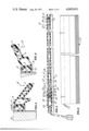
- FIG. 1 is a fragmentary perspective view of the device of the invention with a distal wall section of the flexible housing of the device and a switch and switch operating assembly housed therein, shown in longitudinal cross section.
- FIG. 2 is a perspective fragmentary view showing the adjacent edges of two doors equipped with touch-sensitive control devices according to the one shown in FIG. 1 with portions in overlapping relationship.
- FIG. 3 is a view of the device of FIGS. 1 and 2 shown in transverse cross section in a deflected condition wherein it is warped in clockwise direction about a proximal portion.
- FIG. 4 is a view in transverse cross section of the device of FIGS. 1 to 3 shown warped in a counter-clockwise direction about its proximal portion.
- FIG. 5 is a fragmentary shortened end view of a touch-sensitive door-opening control device of modified construction showing in the foreground the distal portion of the device with wall sections broken away to expose switch and switch operating assembly shown in section.
- FIG. 6 is a shortened side view of the device shown in FIG. 5.
- a touch-sensitive control device 5, 5L or 5R comprises a tubiform housing 6 and an electrical switch and switch operating assembly 7 which includes a sleeve 27, a switch 28, cable 29 and other items detailed below received in a passageway 8 of the housing.
- the device 5 is shown in an S-shaped configuration of somewhat exaggerated curvature to illustrate that vehicles are now being designed which have an outer side contour of S cross section in a vertical plane.
- the housing 6 is of known construction comprising a rubber or rubber-like material having, in addition to passageway 8, passageway 10, 11, and 12.
- the passageway 10 and 11 are sufficiently large to provide a wall weakening effect.
- the housing is shaped along a horizontal cross section with an enlarged intermediate portion extending the full length of the housing formed by the walls of the housing which surround the passageway 11. A proximal portion of the housing encloses the passageway 12.
- FIGS. 3 and 4 illustrate that the housing 6 is readily warpable when subjected to lateral forces in the direction of the arrows 14, 15. It may be noted that the greatest deformation in the walls of the housing occur in a hollow intermediate portion of the housing 6, i.e., in those walls surrounding the passageway 11.
- the housing 6 is secured to a door 22 by the bracket 20 which provides a C portion terminating in the edges 19, 21.
- the C portion of the bracket substantially encloses a proximal portion 24 of the housing.
- the bracket is constituted of metal or other rigid material which retains the proximal portion of the housing 6 in substantially rigid relation regardless of warping forces applied to the distal portion.
- the device 5 has been constructed in actual practice with a housing measuring 31/4 inches between its proximal and distal ends, 5/8 of an inch crosswise of its distal portion, 11/4 inches across its intermediate portion surrounding passageway 11, 1 inch across the intermediate portion in its proximal-to-distal direction, 15/8 inches lengthwise of the narrow distal portion in the proximal-to-distal direction, with all walls being of approximately 1/8 inch thickness.
- the passageway 8 was approximately 3/8 inch by 11/16 inch.
- the assembly as illustrated in FIG. 1 comprises a switch 26 and a switch-supporting sleeve 27 fixed within one end of passageway 8, an anchor 28 within the other end of passageway 8, a cable 29 extending between the anchor 28 and a switch actuating follower 31, a compression spring 32 housed by the sleeve 27 acting between the follower 31 and a plug 33 secured within the inner end of the sleeve 27, a plurality of spacer blocks 35 of conforming but slightly smaller contour than the inner surface of passageway 8 spaced substantially uniformly lengthwise thereof. As shown, the blocks 35 are spaced along the cable by being confined between a pair of cable clamps 36.
- the switch 26 is preferably located in the upper end of the passageway 8 for greater freedom from moisture and dirt. It is supported to this location by a sleeve 27 secured to a fixed position within the passageway by means, such as an adhesive or the clamping arrangement described with respect to the second described embodiment below.
- the switch has a threaded portion 38 received in a threaded aperture 39 of the sleeve. Relative rotation of the switch in the sleeve is prevented by a lock nut 41 turned tightly against the top surface of the sleeve.
- the sleeve has a threaded internal surface 42 which receives the centrally apertured plug 33 which is adjusted inwardly of the surface 42 to put sufficient compressive force on the spring 32 in the follower 31 seated on the spring to engage and lift a spring-loaded plunger 44 of the switch 26 out of its normally circuit-closing position.
- the follower 31 has a stem 46 into which the cable 29 extends and is secured.
- Installation of the switch and switch-operating assembly 7 is achieved by preassembling the assembly exteriorly of the housing 6 and then lacing the assembly in a linear fashion through the passageway 8. Entry of the assembly into the passageway may be accomplished at either end but a practical procedure is to have the anchor 28 in place and fixed to the interior of the passageway 8, then with a lacing strand extending through the passageway attached to the lower end of the cable 29, draw the assembly into the top end of the passageway 8 and through the passageway until the cable 29 protrudes through the anchor 28 with the spring 32 compressed out of its normal state. Thereupon, a cable clamp 46 may be attached to the cable 29 to seat on the outer end surface of the plug 47 of the sleeve 48 of the anchor.
- the plug may thereafter be turned to attain the proper tautness of the cable 29 and the proper position of the follower for holding the switch 26 open.
- the position of the follower 31 through linear adjustment of the cable should be such as to merely hold the switch out of closed condition so that, upon slight deformation of the distal portion of the housing 6, the increased tension in the cable would tend to bring about closing of the switch and the intended emergency retraction of the door 22.
- FIG. 2 illustrates a type of door arrangement common in the construction of mass transit track or highway vehicles in which two doors are reciprocated toward and away from each other to close and open a vehicle doorway.
- devices 5L and 5R are shown to have housing 6 which is normally cut from the same extrusion stock but may be mounted on a pair of separating doors of convex outward exterior with opposite curvatures to flexibly conform to the side curvature of a vehicle regardless of the side of the housing presented to the exterior of the vehicle.
- the housing 6 of devices 5L and 5R are admirably suited to meet in overlapping relationship with the most distal surface 51 of one of the housings in adjacent relation with an interior angle surface 52 of the opposite housing.
- the ability of the housings 6 to conform either to concave or convex curvatures is illustrated also in FIG. 1.
- FIGS. 5 and 6 illustrate a device 5S that is similar to devices 5L and 5R except for details in the construction of the switch and switch-actuating assembly 75.
- assembly 75 the threaded portion 38 of the switch extends in threaded relation into the interior surface of the wall of a sleeve 61 and is adjustable lengthwise of the sleeve by reason of this threaded relationship.
- the switch and the sleeve are made relatively nonrotatable by tightening of the nut 41 tightly against the end of the sleeve.
- the lower end of the sleeve 61 is closed except for a central aperture for accommodating the cable 62 or a follower stem.
- the closed end wall 63 of the sleeve provides a seat for a spring 64 having an upward seat on a follower 65.
- the follower 65 is fixed to the upper end of the cable 62 and engages the plunger 44 of the switch to hold the switch out of circuit-closing condition when the switch is screwed inwardly of the sleeve to a proper position in correlation with a longitudinal adjustment of the cable within the anchor 71 to produce cable tautness.
- the anchor 71 comprises a sleeve 72 having an external groove 73 and a threaded stem 70 secured to the cable 62 in threaded relation with the fastener or nut 83.
- Spacer blocks 77 are held in place by tubular elements 78 pinched into clamping relation with the cable.
- the blocks 77 are spaced uniformly within the passageway 8 of the housing 6.
- the blocks and the bushings are of outside dimensions which enable the assembly 75 to be drawn readily through the passageway 8 into the position shown in FIG. 5.
- the sleeve 61 is somewhat slightly larger than the sleeve 72 and its entry for short distance into the top of the passageway 8 may be facilitated by use of a lubricant.
- the assembly is secured into place by clamping rings 81, 82 which pinch the wall of the casing into conformity with the grooves 74, 73. Once the rings 81, 82 are in place, the stem 70 may be turned to a proper position relative to the sleeve to obtain a desired tautness in the cable 62 which allows closing of the switch as a distal portion of the housing 6 is warped through manual contact.
Priority Applications (9)
| Application Number | Priority Date | Filing Date | Title |
|---|---|---|---|
| US05/672,871 US4045631A (en) | 1976-04-02 | 1976-04-02 | Touch-sensitive door control switch |
| CA272,655A CA1067600A (fr) | 1976-04-02 | 1977-02-25 | Dispositif sensible de commande de portiere |
| GB9763/77A GB1523419A (en) | 1976-04-02 | 1977-03-08 | Touch-sensitive control device |
| DE19772714280 DE2714280A1 (de) | 1976-04-02 | 1977-03-31 | Beruehrungssensitive steuereinrichtung fuer fahrzeugtueren |
| FR7709667A FR2346540A1 (fr) | 1976-04-02 | 1977-03-31 | Dispositif de commande de porte, sensible au contact |
| IT21914/77A IT1076649B (it) | 1976-04-02 | 1977-03-31 | Dispositivo di comando per porte sensibile al tocco |
| JP3744277A JPS52120380A (en) | 1976-04-02 | 1977-03-31 | Contacttsensing control device |
| SE7703870A SE7703870L (sv) | 1976-04-02 | 1977-04-01 | Beroringskenslig dorrmanovreringsanordning |
| ES1977227612U ES227612Y (es) | 1976-04-02 | 1977-04-01 | Nuevo aparato de control sensible al contacto. |
Applications Claiming Priority (1)
| Application Number | Priority Date | Filing Date | Title |
|---|---|---|---|
| US05/672,871 US4045631A (en) | 1976-04-02 | 1976-04-02 | Touch-sensitive door control switch |
Publications (1)
| Publication Number | Publication Date |
|---|---|
| US4045631A true US4045631A (en) | 1977-08-30 |
Family
ID=24700359
Family Applications (1)
| Application Number | Title | Priority Date | Filing Date |
|---|---|---|---|
| US05/672,871 Expired - Lifetime US4045631A (en) | 1976-04-02 | 1976-04-02 | Touch-sensitive door control switch |
Country Status (9)
| Country | Link |
|---|---|
| US (1) | US4045631A (fr) |
| JP (1) | JPS52120380A (fr) |
| CA (1) | CA1067600A (fr) |
| DE (1) | DE2714280A1 (fr) |
| ES (1) | ES227612Y (fr) |
| FR (1) | FR2346540A1 (fr) |
| GB (1) | GB1523419A (fr) |
| IT (1) | IT1076649B (fr) |
| SE (1) | SE7703870L (fr) |
Cited By (18)
| Publication number | Priority date | Publication date | Assignee | Title |
|---|---|---|---|---|
| US4133365A (en) * | 1977-06-08 | 1979-01-09 | Vapor Corporation | Obstruction sensing edge for a bifolding door |
| US4340825A (en) * | 1980-09-26 | 1982-07-20 | Varian Associates, Inc. | Touch detector for electron applicator |
| EP0280191A1 (fr) * | 1987-02-18 | 1988-08-31 | Knorr-Bremse Ag | Sécurité antipincement pour une porte |
| US4785143A (en) * | 1987-08-17 | 1988-11-15 | Miller Norman K | Safety edge for a door |
| EP0359051A1 (fr) * | 1988-08-31 | 1990-03-21 | GfA-Antriebstechnik GmbH | Dispositif de sécurité du bord antérieur des portes |
| US4972054A (en) * | 1989-07-21 | 1990-11-20 | Miller Edge, Inc. | Redundant sensing edge for a door |
| US5023411A (en) * | 1989-07-21 | 1991-06-11 | Miller Edge, Inc. | Sensing edgeswitch for a door |
| US5225640A (en) * | 1992-05-12 | 1993-07-06 | Miller Edge, Inc. | Sensing edge |
| US5265324A (en) * | 1992-05-12 | 1993-11-30 | Miller Edge, Inc. | Method of making a sensing edge |
| US5345671A (en) * | 1992-05-12 | 1994-09-13 | Miller Edge, Inc. | Process of making a sensing edge with a failsafe sensor |
| US5921026A (en) * | 1995-06-07 | 1999-07-13 | Miller Edge, Inc. | Adjustable height sensing edge for a door |
| US5929406A (en) * | 1996-11-19 | 1999-07-27 | Wampfler Aktiengesellschaft | Safety strips for closing edges |
| EP1288420A1 (fr) * | 2001-08-31 | 2003-03-05 | HÜBNER GmbH | Dispositif d'étanchéité de portes |
| EP2302155A1 (fr) * | 1997-12-24 | 2011-03-30 | Asmo Co., Ltd. | Dispositif d'ouverture/fermeture automatique |
| US20110169513A1 (en) * | 2009-12-08 | 2011-07-14 | Magna Closures Inc. | Wide activation angle pinch sensor section and sensor hook-on attachment principle |
| US20140157670A1 (en) * | 2012-12-10 | 2014-06-12 | Hyundai Motor Company | Sliding door device for vehicle |
| US9234979B2 (en) | 2009-12-08 | 2016-01-12 | Magna Closures Inc. | Wide activation angle pinch sensor section |
| US20170050503A1 (en) * | 2015-08-19 | 2017-02-23 | Lippert Components, Inc. | Bus door seal |
Families Citing this family (6)
| Publication number | Priority date | Publication date | Assignee | Title |
|---|---|---|---|---|
| DE2758272A1 (de) * | 1977-12-27 | 1979-07-05 | Rolf Andersson | Klemmschutz, insbesondere fuer tore mit motorantrieb |
| DE2917797C2 (de) * | 1979-05-03 | 1982-06-24 | Gebr. Bode & Co, 3500 Kassel | Einklemmsicherung für selbsttätig öffnende und schließende Türen |
| ATE34010T1 (de) * | 1984-08-06 | 1988-05-15 | Gilgen Ag Jakob | Schaltleiste zum schutz von personen und gegenstaenden. |
| DE9414584U1 (de) * | 1994-09-09 | 1996-01-18 | Gfa Ges Fuer Antriebstechnik D | Schalteranordnung für eine Schließkantensicherung |
| DE19533431A1 (de) * | 1994-09-09 | 1996-05-15 | Gfa Ges Fuer Antriebstechnik D | Schalteranordnung für eine Schließkantensicherung |
| DE102006055706B4 (de) * | 2006-11-23 | 2010-07-29 | Bircher Reglomat Ag | Schaltelement für motorisch bewegte Türen, Tore od. dgl. und Montageverfahren hierzu |
Citations (6)
| Publication number | Priority date | Publication date | Assignee | Title |
|---|---|---|---|---|
| US1576950A (en) * | 1921-04-11 | 1926-03-16 | Nat Pneumatic Co | Safety shoe-tripping mechanism for doors |
| US2048514A (en) * | 1934-03-12 | 1936-07-21 | Peelle Co The | Operator for elevator gates |
| US2135131A (en) * | 1937-02-15 | 1938-11-01 | Elevator Supplies Co Inc | Sensitive door edge structure |
| US2437969A (en) * | 1946-01-24 | 1948-03-16 | Elliott F Barlow | Deformable switch |
| US2493157A (en) * | 1947-12-10 | 1950-01-03 | Charles N Merralls | Treadle switch |
| US3670119A (en) * | 1971-03-02 | 1972-06-13 | Switches Inc | Switch with improved actuator means |
Family Cites Families (1)
| Publication number | Priority date | Publication date | Assignee | Title |
|---|---|---|---|---|
| FR1494923A (fr) * | 1966-07-29 | 1966-07-29 | Paris & Du Rhone | Perfectionnement à la commande électrique des mécanismes lève-glace pour véhicules automobiles et analogues |
-
1976
- 1976-04-02 US US05/672,871 patent/US4045631A/en not_active Expired - Lifetime
-
1977
- 1977-02-25 CA CA272,655A patent/CA1067600A/fr not_active Expired
- 1977-03-08 GB GB9763/77A patent/GB1523419A/en not_active Expired
- 1977-03-31 IT IT21914/77A patent/IT1076649B/it active
- 1977-03-31 DE DE19772714280 patent/DE2714280A1/de active Pending
- 1977-03-31 JP JP3744277A patent/JPS52120380A/ja active Pending
- 1977-03-31 FR FR7709667A patent/FR2346540A1/fr not_active Withdrawn
- 1977-04-01 SE SE7703870A patent/SE7703870L/xx unknown
- 1977-04-01 ES ES1977227612U patent/ES227612Y/es not_active Expired
Patent Citations (6)
| Publication number | Priority date | Publication date | Assignee | Title |
|---|---|---|---|---|
| US1576950A (en) * | 1921-04-11 | 1926-03-16 | Nat Pneumatic Co | Safety shoe-tripping mechanism for doors |
| US2048514A (en) * | 1934-03-12 | 1936-07-21 | Peelle Co The | Operator for elevator gates |
| US2135131A (en) * | 1937-02-15 | 1938-11-01 | Elevator Supplies Co Inc | Sensitive door edge structure |
| US2437969A (en) * | 1946-01-24 | 1948-03-16 | Elliott F Barlow | Deformable switch |
| US2493157A (en) * | 1947-12-10 | 1950-01-03 | Charles N Merralls | Treadle switch |
| US3670119A (en) * | 1971-03-02 | 1972-06-13 | Switches Inc | Switch with improved actuator means |
Cited By (23)
| Publication number | Priority date | Publication date | Assignee | Title |
|---|---|---|---|---|
| US4133365A (en) * | 1977-06-08 | 1979-01-09 | Vapor Corporation | Obstruction sensing edge for a bifolding door |
| US4340825A (en) * | 1980-09-26 | 1982-07-20 | Varian Associates, Inc. | Touch detector for electron applicator |
| EP0280191A1 (fr) * | 1987-02-18 | 1988-08-31 | Knorr-Bremse Ag | Sécurité antipincement pour une porte |
| US4785143A (en) * | 1987-08-17 | 1988-11-15 | Miller Norman K | Safety edge for a door |
| EP0359051A1 (fr) * | 1988-08-31 | 1990-03-21 | GfA-Antriebstechnik GmbH | Dispositif de sécurité du bord antérieur des portes |
| US4972054A (en) * | 1989-07-21 | 1990-11-20 | Miller Edge, Inc. | Redundant sensing edge for a door |
| US5023411A (en) * | 1989-07-21 | 1991-06-11 | Miller Edge, Inc. | Sensing edgeswitch for a door |
| US5345671A (en) * | 1992-05-12 | 1994-09-13 | Miller Edge, Inc. | Process of making a sensing edge with a failsafe sensor |
| WO1993023864A1 (fr) * | 1992-05-12 | 1993-11-25 | Miller Edge, Inc. | Bordure de detection |
| US5265324A (en) * | 1992-05-12 | 1993-11-30 | Miller Edge, Inc. | Method of making a sensing edge |
| US5225640A (en) * | 1992-05-12 | 1993-07-06 | Miller Edge, Inc. | Sensing edge |
| US5921026A (en) * | 1995-06-07 | 1999-07-13 | Miller Edge, Inc. | Adjustable height sensing edge for a door |
| US5929406A (en) * | 1996-11-19 | 1999-07-27 | Wampfler Aktiengesellschaft | Safety strips for closing edges |
| EP2302155A1 (fr) * | 1997-12-24 | 2011-03-30 | Asmo Co., Ltd. | Dispositif d'ouverture/fermeture automatique |
| EP1288420A1 (fr) * | 2001-08-31 | 2003-03-05 | HÜBNER GmbH | Dispositif d'étanchéité de portes |
| US20110169513A1 (en) * | 2009-12-08 | 2011-07-14 | Magna Closures Inc. | Wide activation angle pinch sensor section and sensor hook-on attachment principle |
| US8493081B2 (en) | 2009-12-08 | 2013-07-23 | Magna Closures Inc. | Wide activation angle pinch sensor section and sensor hook-on attachment principle |
| US9234979B2 (en) | 2009-12-08 | 2016-01-12 | Magna Closures Inc. | Wide activation angle pinch sensor section |
| US9417099B2 (en) | 2009-12-08 | 2016-08-16 | Magna Closures Inc. | Wide activation angle pinch sensor section |
| US20140157670A1 (en) * | 2012-12-10 | 2014-06-12 | Hyundai Motor Company | Sliding door device for vehicle |
| US9334684B2 (en) * | 2012-12-10 | 2016-05-10 | Hyundai Motor Company | Sliding door device for vehicle |
| US20170050503A1 (en) * | 2015-08-19 | 2017-02-23 | Lippert Components, Inc. | Bus door seal |
| US9751390B2 (en) * | 2015-08-19 | 2017-09-05 | Lippert Components, Inc. | Bus door seal |
Also Published As
| Publication number | Publication date |
|---|---|
| IT1076649B (it) | 1985-04-27 |
| DE2714280A1 (de) | 1977-10-06 |
| JPS52120380A (en) | 1977-10-08 |
| ES227612U (es) | 1977-06-01 |
| GB1523419A (en) | 1978-08-31 |
| FR2346540A1 (fr) | 1977-10-28 |
| ES227612Y (es) | 1977-11-01 |
| SE7703870L (sv) | 1977-10-03 |
| CA1067600A (fr) | 1979-12-04 |
Similar Documents
| Publication | Publication Date | Title |
|---|---|---|
| US4045631A (en) | Touch-sensitive door control switch | |
| US4805345A (en) | Sealing device for a door | |
| US7469617B2 (en) | Tension compensating assembly for mechanical control cables | |
| US6041549A (en) | Device for linking a window lifter arm to the movable window pane of a motor vehicle | |
| US4090329A (en) | Window operating mechanism | |
| JPH0596954A (ja) | シール成形体 | |
| US3793772A (en) | Safety molding for electrically actuated sliding windows | |
| US4684768A (en) | Resilient sectional strip for mounting to a closure edge | |
| US4637166A (en) | Wire compensator for a wire driving window regulator | |
| BR0009434A (pt) | Dispositivo de regulagem para janela com dobradiça | |
| BR102018017260A2 (pt) | Dispositivo de guia para guiar um cabo para uma porta deslizante pivotante preferencialmente de duas folhas | |
| ES2100610T3 (es) | Fuelle para instalar entre dos unidades de vehiculo con acoplamiento articulado. | |
| US3366027A (en) | Adjustable tension hingeless ventilator | |
| JPH0666061A (ja) | 窓支持装置および車両窓巻き上げ機構 | |
| IT1260455B (it) | Deflettore del vento per un veicolo con una parte mobile del tetto | |
| KR200150766Y1 (ko) | 자동차의 슬라이딩 글래스 소음 방지장치 | |
| US5435199A (en) | Hand-brake lever | |
| US2238877A (en) | Rearview mirror | |
| US1867776A (en) | Sliding window | |
| KR870000689Y1 (ko) | 차량용 라버웨더 스트립 | |
| KR0115641Y1 (ko) | 차량의 테일게이트 개폐장치 | |
| KR0120271Y1 (ko) | 힌지를 이용한 차량용 도어 체커 | |
| US3024489A (en) | Window balancing device | |
| KR0121339Y1 (ko) | 차량용 도어 바디 사이드 웨더스트립 | |
| KR19980035756U (ko) | 자동차의 트렁크 리드 완충용 스토퍼 |
Legal Events
| Date | Code | Title | Description |
|---|---|---|---|
| AS | Assignment |
Owner name: MIDBRAKE CORPORATION, OWOSSON, MI., A CORP. OF DEL Free format text: ASSIGNMENT OF ASSIGNORS INTEREST.;ASSIGNOR:MIDLAND-ROSS CORPORATION;REEL/FRAME:004061/0714 Effective date: 19820830 |
|
| STCF | Information on status: patent grant |
Free format text: PATENTED FILE - (OLD CASE ADDED FOR FILE TRACKING PURPOSES) |