US20130114234A1 - Lightweight electronic system for automotive applications and method - Google Patents
Lightweight electronic system for automotive applications and method Download PDFInfo
- Publication number
- US20130114234A1 US20130114234A1 US13/668,461 US201213668461A US2013114234A1 US 20130114234 A1 US20130114234 A1 US 20130114234A1 US 201213668461 A US201213668461 A US 201213668461A US 2013114234 A1 US2013114234 A1 US 2013114234A1
- Authority
- US
- United States
- Prior art keywords
- wall portion
- case
- assembly
- wall portions
- integrally formed
- Prior art date
- Legal status (The legal status is an assumption and is not a legal conclusion. Google has not performed a legal analysis and makes no representation as to the accuracy of the status listed.)
- Granted
Links
- 238000000034 method Methods 0.000 title claims abstract description 74
- 239000000463 material Substances 0.000 claims abstract description 39
- 239000002131 composite material Substances 0.000 claims abstract description 22
- 238000004519 manufacturing process Methods 0.000 claims description 41
- 239000002861 polymer material Substances 0.000 claims description 18
- 238000000465 moulding Methods 0.000 claims description 17
- 239000004020 conductor Substances 0.000 claims description 16
- 230000000694 effects Effects 0.000 claims description 14
- 238000002347 injection Methods 0.000 claims description 13
- 239000007924 injection Substances 0.000 claims description 13
- 238000001746 injection moulding Methods 0.000 claims description 8
- 229910052782 aluminium Inorganic materials 0.000 claims description 7
- XAGFODPZIPBFFR-UHFFFAOYSA-N aluminium Chemical compound [Al] XAGFODPZIPBFFR-UHFFFAOYSA-N 0.000 claims description 7
- 239000012530 fluid Substances 0.000 claims description 2
- 230000017525 heat dissipation Effects 0.000 claims description 2
- 239000011261 inert gas Substances 0.000 claims 1
- 238000009751 slip forming Methods 0.000 claims 1
- 230000008569 process Effects 0.000 abstract description 41
- 229920000642 polymer Polymers 0.000 abstract description 15
- 239000004033 plastic Substances 0.000 description 43
- 229920003023 plastic Polymers 0.000 description 43
- 229910052751 metal Inorganic materials 0.000 description 42
- 239000002184 metal Substances 0.000 description 42
- 230000007246 mechanism Effects 0.000 description 26
- 238000013461 design Methods 0.000 description 16
- 239000000047 product Substances 0.000 description 15
- GOFFZTAPOOICFT-UHFFFAOYSA-N 1,3,5-trichloro-2-(2,3-dichlorophenyl)benzene Chemical compound ClC1=CC(Cl)=CC(Cl)=C1C1=CC=CC(Cl)=C1Cl GOFFZTAPOOICFT-UHFFFAOYSA-N 0.000 description 11
- 238000001125 extrusion Methods 0.000 description 11
- 239000010410 layer Substances 0.000 description 11
- 230000014759 maintenance of location Effects 0.000 description 11
- 238000013459 approach Methods 0.000 description 10
- RKUAZJIXKHPFRK-UHFFFAOYSA-N 1,3,5-trichloro-2-(2,4-dichlorophenyl)benzene Chemical compound ClC1=CC(Cl)=CC=C1C1=C(Cl)C=C(Cl)C=C1Cl RKUAZJIXKHPFRK-UHFFFAOYSA-N 0.000 description 9
- 230000008901 benefit Effects 0.000 description 9
- 238000009434 installation Methods 0.000 description 9
- 208000032365 Electromagnetic interference Diseases 0.000 description 8
- 230000015572 biosynthetic process Effects 0.000 description 7
- 230000006378 damage Effects 0.000 description 7
- 238000010276 construction Methods 0.000 description 6
- 238000001816 cooling Methods 0.000 description 6
- 230000006870 function Effects 0.000 description 6
- 150000003071 polychlorinated biphenyls Chemical class 0.000 description 6
- 238000010079 rubber tapping Methods 0.000 description 6
- 238000012546 transfer Methods 0.000 description 6
- 230000002829 reductive effect Effects 0.000 description 5
- 230000000712 assembly Effects 0.000 description 4
- 238000000429 assembly Methods 0.000 description 4
- 230000000670 limiting effect Effects 0.000 description 4
- 239000002991 molded plastic Substances 0.000 description 4
- 230000002093 peripheral effect Effects 0.000 description 4
- -1 polypropylene Polymers 0.000 description 4
- 230000000717 retained effect Effects 0.000 description 4
- 230000003068 static effect Effects 0.000 description 4
- 238000012360 testing method Methods 0.000 description 4
- IJGRMHOSHXDMSA-UHFFFAOYSA-N Atomic nitrogen Chemical compound N#N IJGRMHOSHXDMSA-UHFFFAOYSA-N 0.000 description 3
- 239000004743 Polypropylene Substances 0.000 description 3
- 239000011521 glass Substances 0.000 description 3
- 238000003780 insertion Methods 0.000 description 3
- 230000037431 insertion Effects 0.000 description 3
- 238000011068 loading method Methods 0.000 description 3
- 238000012986 modification Methods 0.000 description 3
- 230000004048 modification Effects 0.000 description 3
- 229920001155 polypropylene Polymers 0.000 description 3
- 238000003825 pressing Methods 0.000 description 3
- 230000002787 reinforcement Effects 0.000 description 3
- 238000009423 ventilation Methods 0.000 description 3
- 208000016261 weight loss Diseases 0.000 description 3
- 229910000831 Steel Inorganic materials 0.000 description 2
- 229920000122 acrylonitrile butadiene styrene Polymers 0.000 description 2
- 239000004676 acrylonitrile butadiene styrene Substances 0.000 description 2
- 230000009471 action Effects 0.000 description 2
- 239000000853 adhesive Substances 0.000 description 2
- 230000001070 adhesive effect Effects 0.000 description 2
- 238000009924 canning Methods 0.000 description 2
- 238000004891 communication Methods 0.000 description 2
- 238000005336 cracking Methods 0.000 description 2
- 229910001873 dinitrogen Inorganic materials 0.000 description 2
- 230000005611 electricity Effects 0.000 description 2
- 230000008030 elimination Effects 0.000 description 2
- 238000003379 elimination reaction Methods 0.000 description 2
- 238000005516 engineering process Methods 0.000 description 2
- 239000012467 final product Substances 0.000 description 2
- 239000011810 insulating material Substances 0.000 description 2
- 238000005304 joining Methods 0.000 description 2
- 230000013011 mating Effects 0.000 description 2
- 238000010137 moulding (plastic) Methods 0.000 description 2
- 238000004806 packaging method and process Methods 0.000 description 2
- 229920000515 polycarbonate Polymers 0.000 description 2
- 239000004417 polycarbonate Substances 0.000 description 2
- 239000011347 resin Substances 0.000 description 2
- 229920005989 resin Polymers 0.000 description 2
- 239000010959 steel Substances 0.000 description 2
- 238000003860 storage Methods 0.000 description 2
- 238000000489 vacuum metal deposition Methods 0.000 description 2
- 229920001207 Noryl Polymers 0.000 description 1
- 239000004727 Noryl Substances 0.000 description 1
- 229920007019 PC/ABS Polymers 0.000 description 1
- XUIMIQQOPSSXEZ-UHFFFAOYSA-N Silicon Chemical compound [Si] XUIMIQQOPSSXEZ-UHFFFAOYSA-N 0.000 description 1
- 208000027418 Wounds and injury Diseases 0.000 description 1
- 238000003491 array Methods 0.000 description 1
- DMFGNRRURHSENX-UHFFFAOYSA-N beryllium copper Chemical compound [Be].[Cu] DMFGNRRURHSENX-UHFFFAOYSA-N 0.000 description 1
- 239000000919 ceramic Substances 0.000 description 1
- 238000000576 coating method Methods 0.000 description 1
- 239000000470 constituent Substances 0.000 description 1
- 238000011109 contamination Methods 0.000 description 1
- 230000008878 coupling Effects 0.000 description 1
- 238000010168 coupling process Methods 0.000 description 1
- 238000005859 coupling reaction Methods 0.000 description 1
- 238000011161 development Methods 0.000 description 1
- 238000006073 displacement reaction Methods 0.000 description 1
- 238000009826 distribution Methods 0.000 description 1
- 230000009977 dual effect Effects 0.000 description 1
- 239000000428 dust Substances 0.000 description 1
- 229920001971 elastomer Polymers 0.000 description 1
- 239000013536 elastomeric material Substances 0.000 description 1
- 238000004924 electrostatic deposition Methods 0.000 description 1
- 230000002708 enhancing effect Effects 0.000 description 1
- 239000003000 extruded plastic Substances 0.000 description 1
- 239000000945 filler Substances 0.000 description 1
- 239000011888 foil Substances 0.000 description 1
- 239000000446 fuel Substances 0.000 description 1
- 239000007789 gas Substances 0.000 description 1
- 239000004519 grease Substances 0.000 description 1
- 238000005286 illumination Methods 0.000 description 1
- 230000003116 impacting effect Effects 0.000 description 1
- 230000006872 improvement Effects 0.000 description 1
- 208000014674 injury Diseases 0.000 description 1
- 239000012212 insulator Substances 0.000 description 1
- 238000002955 isolation Methods 0.000 description 1
- 238000002372 labelling Methods 0.000 description 1
- 238000010147 laser engraving Methods 0.000 description 1
- 239000007769 metal material Substances 0.000 description 1
- 239000000203 mixture Substances 0.000 description 1
- 229910021392 nanocarbon Inorganic materials 0.000 description 1
- 239000003921 oil Substances 0.000 description 1
- 239000003973 paint Substances 0.000 description 1
- 239000000088 plastic resin Substances 0.000 description 1
- 238000007747 plating Methods 0.000 description 1
- 229920000728 polyester Polymers 0.000 description 1
- 239000002952 polymeric resin Substances 0.000 description 1
- 238000013404 process transfer Methods 0.000 description 1
- 238000012545 processing Methods 0.000 description 1
- 230000000135 prohibitive effect Effects 0.000 description 1
- 230000035755 proliferation Effects 0.000 description 1
- 238000004080 punching Methods 0.000 description 1
- 230000005855 radiation Effects 0.000 description 1
- 238000011084 recovery Methods 0.000 description 1
- 230000009467 reduction Effects 0.000 description 1
- 230000003014 reinforcing effect Effects 0.000 description 1
- 230000004044 response Effects 0.000 description 1
- 230000002441 reversible effect Effects 0.000 description 1
- 239000005060 rubber Substances 0.000 description 1
- 238000000926 separation method Methods 0.000 description 1
- 229910052710 silicon Inorganic materials 0.000 description 1
- 239000010703 silicon Substances 0.000 description 1
- 229910000679 solder Inorganic materials 0.000 description 1
- 238000005476 soldering Methods 0.000 description 1
- 239000007787 solid Substances 0.000 description 1
- 238000000638 solvent extraction Methods 0.000 description 1
- 125000006850 spacer group Chemical group 0.000 description 1
- 241000894007 species Species 0.000 description 1
- 239000000126 substance Substances 0.000 description 1
- 239000002344 surface layer Substances 0.000 description 1
- 229920003002 synthetic resin Polymers 0.000 description 1
- 238000011144 upstream manufacturing Methods 0.000 description 1
- 238000001771 vacuum deposition Methods 0.000 description 1
- 238000013022 venting Methods 0.000 description 1
- 125000000391 vinyl group Chemical group [H]C([*])=C([H])[H] 0.000 description 1
- 229920002554 vinyl polymer Polymers 0.000 description 1
- 230000003313 weakening effect Effects 0.000 description 1
- 238000005303 weighing Methods 0.000 description 1
- 239000013585 weight reducing agent Substances 0.000 description 1
Images


Classifications
-
- H—ELECTRICITY
- H05—ELECTRIC TECHNIQUES NOT OTHERWISE PROVIDED FOR
- H05K—PRINTED CIRCUITS; CASINGS OR CONSTRUCTIONAL DETAILS OF ELECTRIC APPARATUS; MANUFACTURE OF ASSEMBLAGES OF ELECTRICAL COMPONENTS
- H05K9/00—Screening of apparatus or components against electric or magnetic fields
- H05K9/0007—Casings
-
- B—PERFORMING OPERATIONS; TRANSPORTING
- B29—WORKING OF PLASTICS; WORKING OF SUBSTANCES IN A PLASTIC STATE IN GENERAL
- B29C—SHAPING OR JOINING OF PLASTICS; SHAPING OF MATERIAL IN A PLASTIC STATE, NOT OTHERWISE PROVIDED FOR; AFTER-TREATMENT OF THE SHAPED PRODUCTS, e.g. REPAIRING
- B29C59/00—Surface shaping of articles, e.g. embossing; Apparatus therefor
- B29C59/16—Surface shaping of articles, e.g. embossing; Apparatus therefor by wave energy or particle radiation, e.g. infrared heating
-
- B—PERFORMING OPERATIONS; TRANSPORTING
- B60—VEHICLES IN GENERAL
- B60R—VEHICLES, VEHICLE FITTINGS, OR VEHICLE PARTS, NOT OTHERWISE PROVIDED FOR
- B60R11/00—Arrangements for holding or mounting articles, not otherwise provided for
- B60R11/02—Arrangements for holding or mounting articles, not otherwise provided for for radio sets, television sets, telephones, or the like; Arrangement of controls thereof
-
- G—PHYSICS
- G06—COMPUTING; CALCULATING OR COUNTING
- G06F—ELECTRIC DIGITAL DATA PROCESSING
- G06F11/00—Error detection; Error correction; Monitoring
-
- H—ELECTRICITY
- H04—ELECTRIC COMMUNICATION TECHNIQUE
- H04B—TRANSMISSION
- H04B1/00—Details of transmission systems, not covered by a single one of groups H04B3/00 - H04B13/00; Details of transmission systems not characterised by the medium used for transmission
- H04B1/06—Receivers
- H04B1/08—Constructional details, e.g. cabinet
- H04B1/082—Constructional details, e.g. cabinet to be used in vehicles
-
- H—ELECTRICITY
- H04—ELECTRIC COMMUNICATION TECHNIQUE
- H04R—LOUDSPEAKERS, MICROPHONES, GRAMOPHONE PICK-UPS OR LIKE ACOUSTIC ELECTROMECHANICAL TRANSDUCERS; DEAF-AID SETS; PUBLIC ADDRESS SYSTEMS
- H04R1/00—Details of transducers, loudspeakers or microphones
- H04R1/02—Casings; Cabinets ; Supports therefor; Mountings therein
-
- H—ELECTRICITY
- H05—ELECTRIC TECHNIQUES NOT OTHERWISE PROVIDED FOR
- H05K—PRINTED CIRCUITS; CASINGS OR CONSTRUCTIONAL DETAILS OF ELECTRIC APPARATUS; MANUFACTURE OF ASSEMBLAGES OF ELECTRICAL COMPONENTS
- H05K1/00—Printed circuits
- H05K1/02—Details
- H05K1/0213—Electrical arrangements not otherwise provided for
- H05K1/0215—Grounding of printed circuits by connection to external grounding means
-
- H—ELECTRICITY
- H05—ELECTRIC TECHNIQUES NOT OTHERWISE PROVIDED FOR
- H05K—PRINTED CIRCUITS; CASINGS OR CONSTRUCTIONAL DETAILS OF ELECTRIC APPARATUS; MANUFACTURE OF ASSEMBLAGES OF ELECTRICAL COMPONENTS
- H05K13/00—Apparatus or processes specially adapted for manufacturing or adjusting assemblages of electric components
-
- H—ELECTRICITY
- H05—ELECTRIC TECHNIQUES NOT OTHERWISE PROVIDED FOR
- H05K—PRINTED CIRCUITS; CASINGS OR CONSTRUCTIONAL DETAILS OF ELECTRIC APPARATUS; MANUFACTURE OF ASSEMBLAGES OF ELECTRICAL COMPONENTS
- H05K5/00—Casings, cabinets or drawers for electric apparatus
- H05K5/02—Details
- H05K5/0217—Mechanical details of casings
- H05K5/0221—Locks; Latches
-
- H—ELECTRICITY
- H05—ELECTRIC TECHNIQUES NOT OTHERWISE PROVIDED FOR
- H05K—PRINTED CIRCUITS; CASINGS OR CONSTRUCTIONAL DETAILS OF ELECTRIC APPARATUS; MANUFACTURE OF ASSEMBLAGES OF ELECTRICAL COMPONENTS
- H05K5/00—Casings, cabinets or drawers for electric apparatus
- H05K5/02—Details
- H05K5/0217—Mechanical details of casings
- H05K5/0226—Hinges
-
- H—ELECTRICITY
- H05—ELECTRIC TECHNIQUES NOT OTHERWISE PROVIDED FOR
- H05K—PRINTED CIRCUITS; CASINGS OR CONSTRUCTIONAL DETAILS OF ELECTRIC APPARATUS; MANUFACTURE OF ASSEMBLAGES OF ELECTRICAL COMPONENTS
- H05K7/00—Constructional details common to different types of electric apparatus
- H05K7/20—Modifications to facilitate cooling, ventilating, or heating
- H05K7/2039—Modifications to facilitate cooling, ventilating, or heating characterised by the heat transfer by conduction from the heat generating element to a dissipating body
- H05K7/20409—Outer radiating structures on heat dissipating housings, e.g. fins integrated with the housing
- H05K7/20418—Outer radiating structures on heat dissipating housings, e.g. fins integrated with the housing the radiating structures being additional and fastened onto the housing
-
- H—ELECTRICITY
- H05—ELECTRIC TECHNIQUES NOT OTHERWISE PROVIDED FOR
- H05K—PRINTED CIRCUITS; CASINGS OR CONSTRUCTIONAL DETAILS OF ELECTRIC APPARATUS; MANUFACTURE OF ASSEMBLAGES OF ELECTRICAL COMPONENTS
- H05K7/00—Constructional details common to different types of electric apparatus
- H05K7/20—Modifications to facilitate cooling, ventilating, or heating
- H05K7/2039—Modifications to facilitate cooling, ventilating, or heating characterised by the heat transfer by conduction from the heat generating element to a dissipating body
- H05K7/20436—Inner thermal coupling elements in heat dissipating housings, e.g. protrusions or depressions integrally formed in the housing
-
- H—ELECTRICITY
- H05—ELECTRIC TECHNIQUES NOT OTHERWISE PROVIDED FOR
- H05K—PRINTED CIRCUITS; CASINGS OR CONSTRUCTIONAL DETAILS OF ELECTRIC APPARATUS; MANUFACTURE OF ASSEMBLAGES OF ELECTRICAL COMPONENTS
- H05K9/00—Screening of apparatus or components against electric or magnetic fields
- H05K9/0007—Casings
- H05K9/0047—Casings being rigid plastic containers having conductive particles, fibres or mesh embedded therein
-
- H—ELECTRICITY
- H05—ELECTRIC TECHNIQUES NOT OTHERWISE PROVIDED FOR
- H05K—PRINTED CIRCUITS; CASINGS OR CONSTRUCTIONAL DETAILS OF ELECTRIC APPARATUS; MANUFACTURE OF ASSEMBLAGES OF ELECTRICAL COMPONENTS
- H05K9/00—Screening of apparatus or components against electric or magnetic fields
- H05K9/0073—Shielding materials
- H05K9/0079—Electrostatic discharge protection, e.g. ESD treated surface for rapid dissipation of charges
-
- H—ELECTRICITY
- H05—ELECTRIC TECHNIQUES NOT OTHERWISE PROVIDED FOR
- H05K—PRINTED CIRCUITS; CASINGS OR CONSTRUCTIONAL DETAILS OF ELECTRIC APPARATUS; MANUFACTURE OF ASSEMBLAGES OF ELECTRICAL COMPONENTS
- H05K9/00—Screening of apparatus or components against electric or magnetic fields
- H05K9/0073—Shielding materials
- H05K9/0081—Electromagnetic shielding materials, e.g. EMI, RFI shielding
-
- H—ELECTRICITY
- H05—ELECTRIC TECHNIQUES NOT OTHERWISE PROVIDED FOR
- H05K—PRINTED CIRCUITS; CASINGS OR CONSTRUCTIONAL DETAILS OF ELECTRIC APPARATUS; MANUFACTURE OF ASSEMBLAGES OF ELECTRICAL COMPONENTS
- H05K1/00—Printed circuits
- H05K1/02—Details
- H05K1/14—Structural association of two or more printed circuits
- H05K1/141—One or more single auxiliary printed circuits mounted on a main printed circuit, e.g. modules, adapters
-
- H—ELECTRICITY
- H05—ELECTRIC TECHNIQUES NOT OTHERWISE PROVIDED FOR
- H05K—PRINTED CIRCUITS; CASINGS OR CONSTRUCTIONAL DETAILS OF ELECTRIC APPARATUS; MANUFACTURE OF ASSEMBLAGES OF ELECTRICAL COMPONENTS
- H05K2201/00—Indexing scheme relating to printed circuits covered by H05K1/00
- H05K2201/09—Shape and layout
- H05K2201/09009—Substrate related
- H05K2201/09081—Tongue or tail integrated in planar structure, e.g. obtained by cutting from the planar structure
-
- H—ELECTRICITY
- H05—ELECTRIC TECHNIQUES NOT OTHERWISE PROVIDED FOR
- H05K—PRINTED CIRCUITS; CASINGS OR CONSTRUCTIONAL DETAILS OF ELECTRIC APPARATUS; MANUFACTURE OF ASSEMBLAGES OF ELECTRICAL COMPONENTS
- H05K2201/00—Indexing scheme relating to printed circuits covered by H05K1/00
- H05K2201/10—Details of components or other objects attached to or integrated in a printed circuit board
- H05K2201/10227—Other objects, e.g. metallic pieces
- H05K2201/10386—Clip leads; Terminals gripping the edge of a substrate
-
- H—ELECTRICITY
- H05—ELECTRIC TECHNIQUES NOT OTHERWISE PROVIDED FOR
- H05K—PRINTED CIRCUITS; CASINGS OR CONSTRUCTIONAL DETAILS OF ELECTRIC APPARATUS; MANUFACTURE OF ASSEMBLAGES OF ELECTRICAL COMPONENTS
- H05K2201/00—Indexing scheme relating to printed circuits covered by H05K1/00
- H05K2201/10—Details of components or other objects attached to or integrated in a printed circuit board
- H05K2201/10431—Details of mounted components
- H05K2201/10439—Position of a single component
- H05K2201/10446—Mounted on an edge
-
- Y—GENERAL TAGGING OF NEW TECHNOLOGICAL DEVELOPMENTS; GENERAL TAGGING OF CROSS-SECTIONAL TECHNOLOGIES SPANNING OVER SEVERAL SECTIONS OF THE IPC; TECHNICAL SUBJECTS COVERED BY FORMER USPC CROSS-REFERENCE ART COLLECTIONS [XRACs] AND DIGESTS
- Y10—TECHNICAL SUBJECTS COVERED BY FORMER USPC
- Y10T—TECHNICAL SUBJECTS COVERED BY FORMER US CLASSIFICATION
- Y10T29/00—Metal working
- Y10T29/49—Method of mechanical manufacture
- Y10T29/49002—Electrical device making
- Y10T29/49117—Conductor or circuit manufacturing
- Y10T29/49124—On flat or curved insulated base, e.g., printed circuit, etc.
- Y10T29/49126—Assembling bases
-
- Y—GENERAL TAGGING OF NEW TECHNOLOGICAL DEVELOPMENTS; GENERAL TAGGING OF CROSS-SECTIONAL TECHNOLOGIES SPANNING OVER SEVERAL SECTIONS OF THE IPC; TECHNICAL SUBJECTS COVERED BY FORMER USPC CROSS-REFERENCE ART COLLECTIONS [XRACs] AND DIGESTS
- Y10—TECHNICAL SUBJECTS COVERED BY FORMER USPC
- Y10T—TECHNICAL SUBJECTS COVERED BY FORMER US CLASSIFICATION
- Y10T29/00—Metal working
- Y10T29/49—Method of mechanical manufacture
- Y10T29/49002—Electrical device making
- Y10T29/49117—Conductor or circuit manufacturing
- Y10T29/49124—On flat or curved insulated base, e.g., printed circuit, etc.
- Y10T29/49128—Assembling formed circuit to base
-
- Y—GENERAL TAGGING OF NEW TECHNOLOGICAL DEVELOPMENTS; GENERAL TAGGING OF CROSS-SECTIONAL TECHNOLOGIES SPANNING OVER SEVERAL SECTIONS OF THE IPC; TECHNICAL SUBJECTS COVERED BY FORMER USPC CROSS-REFERENCE ART COLLECTIONS [XRACs] AND DIGESTS
- Y10—TECHNICAL SUBJECTS COVERED BY FORMER USPC
- Y10T—TECHNICAL SUBJECTS COVERED BY FORMER US CLASSIFICATION
- Y10T29/00—Metal working
- Y10T29/49—Method of mechanical manufacture
- Y10T29/49002—Electrical device making
- Y10T29/49117—Conductor or circuit manufacturing
- Y10T29/49124—On flat or curved insulated base, e.g., printed circuit, etc.
- Y10T29/4913—Assembling to base an electrical component, e.g., capacitor, etc.
-
- Y—GENERAL TAGGING OF NEW TECHNOLOGICAL DEVELOPMENTS; GENERAL TAGGING OF CROSS-SECTIONAL TECHNOLOGIES SPANNING OVER SEVERAL SECTIONS OF THE IPC; TECHNICAL SUBJECTS COVERED BY FORMER USPC CROSS-REFERENCE ART COLLECTIONS [XRACs] AND DIGESTS
- Y10—TECHNICAL SUBJECTS COVERED BY FORMER USPC
- Y10T—TECHNICAL SUBJECTS COVERED BY FORMER US CLASSIFICATION
- Y10T29/00—Metal working
- Y10T29/49—Method of mechanical manufacture
- Y10T29/49002—Electrical device making
- Y10T29/49117—Conductor or circuit manufacturing
- Y10T29/49169—Assembling electrical component directly to terminal or elongated conductor
- Y10T29/49171—Assembling electrical component directly to terminal or elongated conductor with encapsulating
- Y10T29/49172—Assembling electrical component directly to terminal or elongated conductor with encapsulating by molding of insulating material
-
- Y—GENERAL TAGGING OF NEW TECHNOLOGICAL DEVELOPMENTS; GENERAL TAGGING OF CROSS-SECTIONAL TECHNOLOGIES SPANNING OVER SEVERAL SECTIONS OF THE IPC; TECHNICAL SUBJECTS COVERED BY FORMER USPC CROSS-REFERENCE ART COLLECTIONS [XRACs] AND DIGESTS
- Y10—TECHNICAL SUBJECTS COVERED BY FORMER USPC
- Y10T—TECHNICAL SUBJECTS COVERED BY FORMER US CLASSIFICATION
- Y10T29/00—Metal working
- Y10T29/49—Method of mechanical manufacture
- Y10T29/4957—Sound device making
-
- Y—GENERAL TAGGING OF NEW TECHNOLOGICAL DEVELOPMENTS; GENERAL TAGGING OF CROSS-SECTIONAL TECHNOLOGIES SPANNING OVER SEVERAL SECTIONS OF THE IPC; TECHNICAL SUBJECTS COVERED BY FORMER USPC CROSS-REFERENCE ART COLLECTIONS [XRACs] AND DIGESTS
- Y10—TECHNICAL SUBJECTS COVERED BY FORMER USPC
- Y10T—TECHNICAL SUBJECTS COVERED BY FORMER US CLASSIFICATION
- Y10T29/00—Metal working
- Y10T29/49—Method of mechanical manufacture
- Y10T29/49826—Assembling or joining
- Y10T29/49861—Sizing mating parts during final positional association
-
- Y—GENERAL TAGGING OF NEW TECHNOLOGICAL DEVELOPMENTS; GENERAL TAGGING OF CROSS-SECTIONAL TECHNOLOGIES SPANNING OVER SEVERAL SECTIONS OF THE IPC; TECHNICAL SUBJECTS COVERED BY FORMER USPC CROSS-REFERENCE ART COLLECTIONS [XRACs] AND DIGESTS
- Y10—TECHNICAL SUBJECTS COVERED BY FORMER USPC
- Y10T—TECHNICAL SUBJECTS COVERED BY FORMER US CLASSIFICATION
- Y10T29/00—Metal working
- Y10T29/53—Means to assemble or disassemble
- Y10T29/5313—Means to assemble electrical device
-
- Y—GENERAL TAGGING OF NEW TECHNOLOGICAL DEVELOPMENTS; GENERAL TAGGING OF CROSS-SECTIONAL TECHNOLOGIES SPANNING OVER SEVERAL SECTIONS OF THE IPC; TECHNICAL SUBJECTS COVERED BY FORMER USPC CROSS-REFERENCE ART COLLECTIONS [XRACs] AND DIGESTS
- Y10—TECHNICAL SUBJECTS COVERED BY FORMER USPC
- Y10T—TECHNICAL SUBJECTS COVERED BY FORMER US CLASSIFICATION
- Y10T403/00—Joints and connections
- Y10T403/70—Interfitted members
-
- Y—GENERAL TAGGING OF NEW TECHNOLOGICAL DEVELOPMENTS; GENERAL TAGGING OF CROSS-SECTIONAL TECHNOLOGIES SPANNING OVER SEVERAL SECTIONS OF THE IPC; TECHNICAL SUBJECTS COVERED BY FORMER USPC CROSS-REFERENCE ART COLLECTIONS [XRACs] AND DIGESTS
- Y10—TECHNICAL SUBJECTS COVERED BY FORMER USPC
- Y10T—TECHNICAL SUBJECTS COVERED BY FORMER US CLASSIFICATION
- Y10T428/00—Stock material or miscellaneous articles
- Y10T428/24—Structurally defined web or sheet [e.g., overall dimension, etc.]
- Y10T428/24273—Structurally defined web or sheet [e.g., overall dimension, etc.] including aperture
- Y10T428/24281—Struck out portion type
- Y10T428/24289—Embedded or interlocked
-
- Y—GENERAL TAGGING OF NEW TECHNOLOGICAL DEVELOPMENTS; GENERAL TAGGING OF CROSS-SECTIONAL TECHNOLOGIES SPANNING OVER SEVERAL SECTIONS OF THE IPC; TECHNICAL SUBJECTS COVERED BY FORMER USPC CROSS-REFERENCE ART COLLECTIONS [XRACs] AND DIGESTS
- Y10—TECHNICAL SUBJECTS COVERED BY FORMER USPC
- Y10T—TECHNICAL SUBJECTS COVERED BY FORMER US CLASSIFICATION
- Y10T74/00—Machine element or mechanism
- Y10T74/20—Control lever and linkage systems
- Y10T74/20396—Hand operated
Definitions
- the present invention relates generally to apparatus for enclosing electrical subassemblies, and more specifically relates to apparatus for efficiently securing subassemblies to a chassis of an electrical assembly such as an automobile radio, compact disc playing mechanism, cassette tape playing mechanism, navigational aid, personal computer, personal and telematic communication devices or disk drive mechanism.
- an electrical assembly such as an automobile radio, compact disc playing mechanism, cassette tape playing mechanism, navigational aid, personal computer, personal and telematic communication devices or disk drive mechanism.
- Devices such as automobile radios or personal computers contain subassemblies such as cassette playing mechanisms or disk drives that are attached to the chassis using threaded fasteners.
- the chassis provides structural support for the subassemblies and also provides electromagnetic shielding to limit electromagnetic interference (EMI) experienced by, and/or created by the device.
- EMI electromagnetic interference
- the fasteners ensure that each subassembly within the chassis is properly located and securely retained within the chassis.
- fasteners can have numerous drawbacks, particularly in a high volume production setting.
- the process for applying or installing fasteners can vary, but there is usually some degree of automation required, ranging from manually loading a screw into a bit on a pneumatic driver to using self-feeding automated machines.
- the torque applied by the device used to drive the fasteners must be monitored regularly and adjusted in order to assure proper seating of the fasteners.
- sheet metal tolerances, as well as tolerances of the fasteners themselves have to be maintained at tight levels to allow for the minimization of stress in the assembly when aligning multiple fasteners with corresponding holes in the chassis and in the subassembly.
- the assembly cycle time can be very long especially in high volume production.
- An operator assembling the device must typically first obtain the threaded fastener, orient and position it in alignment with the driver bit, then manipulate or actuate the machine to drive the threaded fastener.
- threaded fasteners presents a risk of any one of the following upstream failures occurring: stripping of fastener threads; insufficient torque resulting in an unseated fastener; excessive torque resulting in distension/deformation of the fastener or adjacent electrical components; installation of the wrong fastener type or size; foreign object damage due to fasteners and/or metal shavings dropping onto the assembly and/or subassembly; and stripping of the head of the threaded fastener.
- a fastener installation tool such as a driver and bit can slip off the fastener and impact an electrical component resulting in a damaged assembly.
- the process of driving the self-tapping fasteners into sheet metal often causes shavings of sheet metal to disperse into the assembly. Such shavings have been known to cause electrical failures, such as shorts or corruption of magnetic components that can permanently damage the product. If self-tapping fasteners are not used, an extra production step is required to pre-form threads in the sheet metal of the chassis and/or the subassembly to be installed within the chassis.
- Fasteners further require an additional inventory burden on the production line in that the production line must be continuously stocked with part numbers (fasteners) other than the integral components that add value to the assembly. Also special tools specifically required for assembly, using fasteners, such as drivers and bits, must be continuously monitored and maintained for proper performance, wear and torque specifications. Typically, the top and/or bottom surface of the chassis must be secured in place after the subassembly is attached to the chassis.
- FIG. 1 illustrates the construction of a typical prior art automotive radio/compact disc (CD) player 10 .
- Radio/CD player 10 comprises a radio subassembly whose principle circuit components are carried on a circuit board 12 and a CD player subassembly 14 .
- the circuit board 12 and the CD player 14 are encased within a common chassis 16 made up of sheet metal components.
- Chassis 16 includes a wraparound housing 18 defining a back and sidewalls, a top cover 20 , a bottom cover 22 and a front plate 24 which are interconnected by numerous threaded fasteners to collectively enclose the subassemblies.
- top and bottom covers 20 and 22 are provided with large arrays holes or openings for airflow and ventilation of heat generated within the radio/CD player 10 .
- a convector or heat sink 26 is carried on an outer surface of one of the chassis sidewalls and is interconnected through a port/window 28 to a power device assembly 30 .
- a trim plate assembly 32 along with a support pad 34 and CD dust cover 36 are affixed to the front plate 24 , providing an operator control interface with the radio/CD player 10 .
- Circuit board 12 is electrically in-circuit with the CD player subassembly 14 through an intermediate flex wire cable 38 and with the power device assembly 30 through a jumper cable 40 .
- Information bearing labels 42 and 44 are provided for future reference by the operator and service technicians.
- the radio/CD player 10 is electrically interconnected with an antenna, power supply, speakers and other related systems of a host vehicle by rear-facing connectors 46 carried on the circuit board 12 which are registered with openings 48 in the rear wall of wraparound housing 18 .
- the radio/CD player 10 is mounted within a host vehicle by threaded fasteners passing through openings in mounting features 50 extending from front plate 24 and a rearwardly directed mounting bushing 52 which is threadably affixed to a stud 54 carried on the outer surface of the rear wall 56 of wraparound housing 18 . As best seen in FIGS.
- FIG. 90 illustrates another known stud design including a threaded shank secured to the rear wall 53 of a radio set 51 by a set nut 55 and receiving a molded rubber, plastic or vinyl stud 57 thereover. Note the large number of threaded fasteners 59 .
- the radio/CD player 10 of FIG. 1 is of ordinary complexity and may require fifty or more threaded fasteners to complete the manufacturing process. Installation of that many fasteners may require that the in-process chassis be re-positioned/re-fixtured ten to fifteen times as it passes along an assembly line of eight to ten skilled workers/work stations.
- Vehicle entertainment systems usually include an audio component such as a radio to enable receiving signals from antennas, contain various forms of playback mechanisms, and have the capacity to accept data from user devices like MP3 players.
- the radio has a decorative assembly that provides man-machine interface as well as displaying pertinent data relative to the selected media and audio settings.
- the back-end or chassis is constructed of metal to provide various functions to ensure the performance of the radio in the vehicular environment.
- the structure to contain the mass from playbacks, the heat conductive properties, and the electrical shielding and grounding are just a few of the advantages to using the metal construction. Unfortunately, with the density of the metal, the disadvantage of added weight is a side effect of the typical construction.
- added weight impacts fuel economy, as well as other hidden costs during assembly that can effect the cost of the product, like sharp edges of metal can be a potential hazard for assemblers in the manufacturing plant as well as added weight can limit the packaging of multiple parts in containers for inter and outer plant distribution.
- Devices such as automobile stereos, audio amplifiers, home stereo systems, two-way radios, computers, signal conditioners/amplifiers, compact disc playing mechanisms, and cassette tape playing mechanisms are examples of products that typically require electrical components to amplify signals and regulate power. Accordingly, such devices typically contain numerous electrical components such as single in-line package (SIP) amplifiers and regulators that are typically soldered into printed circuit boards. Such electrical components generate heat in use. The heat must be dissipated away from the electrical components to avoid damage that can be caused by excessive temperatures in the electrical components. For example, excessive temperatures can cause delicate electrical leads to fail or insulating materials to melt, thereby causing a short circuit resulting in damage to, or even failure of, the entire electrical device.
- SIP single in-line package
- a convector is often mounted to an outer surface of such a device to dissipate heat generated by components by transferring the heat away from the components and the device to the convector and then to the air through radiation. In order to accomplish this, it is preferable that the convector be physically in contact with the component. The components and the convector can be pressed together to allow even better heat conduction from the components to the convector. Sometimes an intermediary material such as a thermal pad or silicon grease is used between the component and the convector to assist in creating an adequate heat transfer junction.
- Convectors are made from aluminum due to the high heat conductivity of that material. Convectors often include a plurality of fins to increase the effective surface area of the convector and thereby increase the rate at which the convector can dissipate heat. Typically, aluminum, convectors are formed by an extruding process, during which the fins can also be formed integrally therewith.
- Convectors are usually assembled to the component or components during final assembly of the overall device in which they are used. At final assembly, components such as SIP amplifiers are already soldered into a printed circuit board. The order of assembly can vary as to which component is assembled into the chassis first.
- the printed circuit board can be installed into the chassis before the convector is mounted to the printed circuit board and the chassis. Alternatively, the convector can be mounted to the chassis before the printed circuit board is mounted to the convector. Sometimes, the convector is assembled to the printed circuit board to form a subassembly before being assembled to the chassis.
- components are attached to the convector using a clip and one or more threaded fasteners that extend through a hole in the clip and into a hole in the convector.
- the clip, component and convector must all be simultaneously held in a fixture and then be fastened together with a threaded fastener. If the component includes a hole to accept a threaded fastener, it can be mounted directly to the convector using a threaded fastener that extends through that hole, without using a clip.
- each hole in the convector that receives a fastener must be separately drilled or punched. This is especially true for an extruded convector if the axis of the hole is not aligned with the direction in which the convector is extruded.
- the fastening process can vary, but there is usually some degree of automation required, ranging from manually loading a screw into a bit on a pneumatically or electrically powered driver to using self-feeding screw machines.
- the torque applied by the device must be monitored regularly and adjusted in order to assure proper seating of the fasteners.
- clamping force between the convector and the component should be at a proper level to ensure sufficient heat transfer to the convector.
- clamping force is a function of the type of fastener and its condition and degree of assembly (e.g. the level of torque applied during installation of the fastener).
- a threaded fastener that is not seated all the way will give less clamping force than one that is seated all the way.
- a stripped or improper type of fastener may provide an insufficient clamping force.
- fixturing is often required to hold a component in the proper location while it is mounted to the convector using one or more fasteners.
- fixturing can be very complex and use of such fixturing usually requires extra handling of both the component and of the resulting assembly, thereby adding to the production cycle time and potentially compromising quality of the final product.
- the assembly cycle time can be very long, especially in high volume production.
- the operator must specifically obtain the threaded fastener, bring it in contact with the driver bit, then drive the threaded fastened.
- self-tapping fasteners the process of driving the self-tapping fasteners into metal often causes metal shavings to disperse into the assembly. Such shavings have been known to cause electrical failures that can permanently damage the product. If self-tapping fasteners are not used, an extra production step is necessary to form threads in the metal of the convector.
- Vehicular radio chassis assemblies may typically contain a circuit board assembly and a playback mechanism that may have ground points from the circuit board to the enclosure. They also tend to have heat sinks added for conducting unwanted heat away from the radio circuit board power components to transfer the heat outside of the chassis.
- the enclosure has been constructed of a non-metallic material such as plastic
- the grounding and shielding has been provided by a variety of methods, including, but not limited to using a metal wire mesh that is insert molded with the structure of the plastic enclosure.
- Another method may include using localized shields that are assembled and soldered to the circuit board. However, this approach only provides a shield, not a ground.
- Static electricity is created when two objects having unbalanced charges touch one another, causing the unbalanced charge to transfer between the two objects.
- This phenomenon commonly occurs in homes, vehicles and other environments when the air is dry (i.e. has a characteristic relatively low level of humidity). For instance, when a person slides onto a car seat, electrons may transfer between the two, causing the surface of the person's body to store a charge. When the person, then, touches a vehicle component, the charge may travel (discharge) from the body to the component, thus creating static electricity.
- the object touched is an electronic device, such as a home stereo, home theatre system, computer, vehicle entertainment system or other electronic media system, this electrostatic discharge can be harmful to the sensitive electronic components of the device. For instance, when a person slides onto a vehicle seat and inserts a disc into the car stereo, a charge may travel from the body through the disc to the sensitive electronic components in the vehicle stereo. Similar problems may occur when using DVD and other magnetic media and disc players.
- the present invention provides numerous product and process advantages which collectively result in substantial cost and labor savings.
- the preferred design optimizes the assembly process. It minimizes the required handling of major components and subassemblies during the assembly cycle. Final assembly is optimized, wherein only seven major components and subassemblies are involved. This minimizes the number of work stations and fixtures, in-process transfers between work stations and total assembly cycle time.
- the inventive design permits selection of the optimal mechanical product configuration for a given receiver family. Furthermore, it permits idealized electrical and mechanical building block partitioning for common and unique elements.
- the preferred embodiment of the invention contemplates screwless final assembly without the use of tools, fixtures and assembly machines. This greatly enhances in-process product flow in the factory, improves scheduling of final assembly, and allows labor intensive processes such as stick lead assembly to be largely moved off-line. This greatly reduces both direct and indirect labor requirements. Furthermore, inventory control is simplified inasmuch as position part proliferation is deferred to or near the end of process.
- FIG. 1 is an exploded, perspective view of a prior art automotive radio/CD player combination in a common chassis constructed of sheet metal and a large number of threaded fasteners;
- FIG. 2 is a front-left perspective view of an alternative embodiment of the present invention embodied in an automotive radio/CD player;
- FIG. 3 is an exploded, perspective view of the radio/CD player of FIG. 2 , illustrating the major subcomponents and subassemblies thereof;
- FIG. 4 is an exploded, perspective view of the radio/CD player of FIG. 2 , illustrating final assembly step I in the production thereof wherein the playback mechanism and circuit board assembly are slid and snapped to the faceplate;
- FIG. 5 is an exploded, perspective view of the radio/CD player of FIG. 2 , illustrating final assembly step II in the production thereof wherein the case is slid and snapped to the faceplate;
- FIG. 6 is an exploded, perspective view of the radio/CD player of FIG. 2 , illustrating final assembly step III in the production thereof wherein the power device retainer clip and heat sink are consecutively anchored, pivoted and snapped to the side of the case;
- FIG. 7 is an exploded, perspective view of the radio/CD player of FIG. 2 , illustrating final assembly step IV in the production thereof wherein the trim plate assembly is snapped to the faceplate/back-end assembly;
- FIG. 8 is a bottom plan view of the radio/CD player of FIG. 2 ;
- FIG. 9 is a left side plan view of the radio/CD player of FIG. 2 ;
- FIG. 10 is a rear plan view of the radio/CD player of FIG. 2 ;
- FIG. 11 is a perspective view of the circuit board assembly with ground clips installed thereon;
- FIG. 12 is a fragmentary, cross-sectional view of a ground clip and an associated portion of the printed circuit board on an enlarged scale in assembly with an adjacent portion of the case to effect a grounding point with the integral wire mesh;
- FIG. 13 is a fragmentary, perspective view of a keypad grounding clip integrally formed on the front side of the faceplate;
- FIG. 14 is a cross-sectional view taken on lines 14 - 14 of FIG. 13 ;
- FIG. 15 is a cross-sectional view taken on lines 15 - 15 of FIG. 13 ;
- FIG. 16 is a cross-sectional view taken on lines 16 - 16 of FIG. 13 ;
- FIG. 17 is a front perspective view of a prior art faceplate illustrating rivet/staked spring clips for ESD protection to associated contact pads on a trim plate assembly;
- FIG. 18 is an exploded, perspective view of a second alternative embodiment of a radio/CD player featuring an unfolded case which provides a single plane bottom up assembly configuration;
- FIG. 19 is a representative cross-section of the case wall structure of the radio/CD player of FIG. 18 , on a greatly enlarged scale, illustrating a thin wall section forming a living hinge;
- FIG. 20 is a fragmentary, cross-sectional detail of adjacent case panel edge portions of the radio/CD player of FIG. 18 , on an enlarged scale, in a post assembly orientation prior to engagement of cooperating integral latch features;
- FIG. 21 is a fragmentary, cross-sectional detail of adjacent case panel edge portions of the radio/CD player of FIG. 18 , similar to that of FIG. 20 , in a post assembly orientation after engagement of cooperating integral latch features;
- FIG. 22 is a representative cross-sectional detail of a variant of the case wall structure of the radio/CD player of FIG. 18 , on a greatly enlarged scale, illustrating a screen only section forming a living hinge;
- FIG. 23 is a schematic representation of manufacturing process equipment for producing a continuous strip of composite/laminate (plastic-screen-plastic) material for subsequent formation of the case structure of the radio/CD player of FIG. 18 ;
- FIG. 24 is a representative view, on a greatly enlarged scale, of laminate case material produced by the process equipment of FIG. 23 , illustrating a localized deformation of the material to define a reduced thickness, undulating living hinge section;
- FIG. 25 is a schematic representation of alternative manufacturing process equipment for producing a continuous strip of composite (plastic & screen) material for subsequent formation of a case structure suitable for the radio/CD player of FIG. 18 ;
- FIG. 26 is a front perspective view of an alternative embodiment of the invention, substantially similar to that of FIG. 2 , but with I/O control device function graphical detail highlighted;
- FIG. 27 is a front perspective view of the interior surface details of the case/back-end of FIG. 10 illustrating the wire mesh screen which has been insert molded within the case adjacent the inner surface portions thereof;
- FIG. 28 is a front-above perspective view of a partially assembled radio/CD player, substantially similar to that illustrated in FIG. 7 (prior to installation of the trim plate assembly), illustrating, inter alia, (1) three outwardly directed spring contacts carried by resilient members integrally formed with the faceplate and (2) the juxtaposition of the wire mesh within the faceplate adjacent the outer surface thereof;
- FIG. 29 is a front-left perspective view of the partially assembled radio/CD player of FIG. 28 , illustrating the same features from a different perspective;
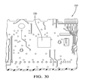
- FIG. 30 is a fragmentary, perspective view of a keyboard assembly printed circuit board carried on the inside surface of the trim plate assembly illustrating one of three contact pads which, after assembly, register with and establish electrical interconnection with spring contacts illustrated in FIGS. 28 and 29 ;
- FIG. 31 is a perspective view of the back side of the trim plate assembly of the prior art radio/CD player illustrated in FIG. 1 , illustrating the surface details thereof;
- FIG. 32 is a broken, bottom-rear perspective view of an audio system assembly embodying an alternative embodiment of the present invention illustrating internal PCB front and rear edge self-grounding with integral features of the audio system housing assembly;
- FIG. 33 is a broken, cross-sectional view, on an enlarged scale, of the rear edge of the PCB of FIG. 32 self-engaging and self-grounding with exposed electrically conductive shield and guide tangs integrally formed with the audio system housing assembly;
- FIG. 34 is a broken, cross-sectional view, on an enlarged scale, of the front edge of the PCB of FIG. 32 self-engaging and self grounding with exposed electrically conductive shield and guide tangs integrally formed with the audio system housing assembly;
- FIG. 35 is a broken, rear facing perspective view of the exposed electrically conductive shield and guide tangs of FIG. 33 , with the PCB removed;
- FIG. 36 is a broken, forward facing perspective view of the exposed electrically conductive shield and guide tangs of FIG. 34 , with the PCB removed;
- FIG. 37 is a broken, perspective, cross-sectional view of an alternative approach to self-grounding a PCB, wherein a rearwardly directed extension of the PCB containing grounding pads on the top or bottom (or both) surfaces thereof registers with an opening formed in the rear wall of the case exposing electrically conductive screen;
- FIG. 38 is a broken, cross-sectional view of the alternative embodiment of FIG. 37 , with the PCB is in its installed design position wherein the extension has pierced the exposed screen and established electrical connection between the grounding pads and the screen;
- FIG. 39 is a bottom-rear perspective view of a CD player subassembly affixed to opposed left and right mounting brackets via integral squirts;
- FIG. 40 is a broken, cross-sectional view, on an enlarged scale, of one of the squirts taken on line 139 - 139 of FIG. 39 , as it is manually applied (as illustrated in phantom) within an adjacent opening in the CD player subassembly;
- FIG. 41 is a broken, perspective view, on an enlarged scale, of one of the squirts of FIG. 39 ;
- FIG. 42 is a top plan view of an alternative embodiment of one of the squirts of FIG. 39 ;
- FIG. 43 is a cross-sectional schematic view of a simplified inventive thermal control apparatus
- FIG. 44 is an exploded, perspective view of a preferred embodiment of a radio/CD player, illustrating the major subcomponents and subassemblies thereof;
- FIG. 45 is a perspective view of a generally planer preform blank as formed, such as be injection molding, prior to beginning the final assembly process;
- FIG. 46 is a perspective view of the radio/CD player of FIG. 44 , illustrating final assembly step I in the production thereof wherein the trim plate assembly is snapped to the outer surface of one of the four wall portions, specifically the front wall portion, defined by the perform blank of FIG. 45 ;
- FIG. 47 is a perspective view of the radio/CD player of FIG. 44 , illustrating final assembly step II in the production thereof wherein the circuit board assembly is slid and snapped to the inner surface of the front wall portion defined by the perform blank of FIG. 45 ;
- FIG. 48 is a perspective view of the radio/CD player of FIG. 44 , illustrating final assembly step III in the production thereof wherein the playback mechanism is slid and snapped to the inner surface of the front wall portion defined by the perform blank of FIG. 45 ;
- FIG. 49 is a perspective view of the radio/CD player of FIG. 44 , illustrating final assembly step IV in the production thereof wherein the remaining three wall portions (top, back and bottom) defined by the perform blank of FIG. 45 are folded by rotation about a first living hinge from a horizontal orientation illustrated in FIG. 48 to a substantially vertical orientation;
- FIG. 50 is a perspective view of the radio/CD player of FIG. 44 , illustrating final assembly step V in the production thereof wherein the remaining two wall portions (back and top) defined by the perform blank of FIG. 45 are folded by rotation about a second living hinge from a vertical orientation illustrated in FIG. 49 to a substantially horizontal orientation;
- FIG. 51 is a perspective view of the radio/CD player of FIG. 44 , illustrating final assembly step VI in the production thereof wherein the remaining wall portion (top) defined by the perform blank of FIG. 45 is folded by rotation about a third living hinge from a horizontal orientation illustrated in FIG. 50 to a substantially horizontal orientation, thus forming the case into a three dimensional configuration;
- FIGS. 52 and 53 are perspective views of the radio/CD player of FIG. 44 , illustrating final assembly step VII in the production thereof wherein the discrete right side wall closure member is installed via snap-fit engagement features and thermally coupled with power devices carried with the circuit board assembly;
- FIG. 54 is a rear side perspective view of the completed radio/CD player
- FIG. 55 is broken segment of the front wall portion interconnected to a broken segment of the bottom wall portion by the first living hinge of FIG. 45 , in an enlarged scale;
- FIG. 56 is a broken cross-sectional view taken along lines 56 - 56 of FIG. 55 ;
- FIG. 57 is a broken cross-sectional view taken along lines 57 - 57 of FIG. 56 ;
- FIGS. 58 and 59 are perspective views of living hinge reinforcement features in the preform blank respectively integrally formed with two adjacent wall portions which self-engage and interlock upon displacement of the adjacent wall portions from a parallel orientation to a normal orientation.
- the present invention can be applied in its broadest sense to electronic devices and systems where shielding from radio frequency interference (RFI), electromagnetic interference (EMI), bulk current injection (BCI) and/or electrostatic discharge (ESD) is required.
- RFID radio frequency interference
- EMI electromagnetic interference
- BCI bulk current injection
- ESD electrostatic discharge
- the invention can be advantageously applied in “infotainment” and telematic systems.
- the present invention employs virtually “fastenerless” design architecture to facilitate low-cost, high volume production techniques.
- a telematics product is a two-way communication/receiver system that enables access by a vehicle occupant to vehicle related information like geographic position/ location through the use of a GPS module with antenna, vehicle diagnostics, crash sensors and air bag deployment. It also contains a phone module that is linked through a microphone in the vehicle and the radio speaker system for hands free calling via voice recognition and links to a call center for a variety of services, including but not limited to emergency help, concierge, vehicle theft recovery, turn-by-turn route guidance, vehicle diagnostics and vehicle unlock.
- the present invention reflects an improved design to reduce the overall weight of an automotive radio/CD player without compromising the strength of the unit.
- the present invention employs a polymer based material that can be molded to provide the necessary features for the chassis as well as the frontal interface to the decorative front-end assembly described for the man-machine interface.
- a polymer based material that can be molded to provide the necessary features for the chassis as well as the frontal interface to the decorative front-end assembly described for the man-machine interface.
- the grounding of the circuit boards may be accomplished by using ground clips attached directly to the ground pads of the circuit board that would interface directly with exposed screen wire mesh of the molded part. While metal is also a good conductor for the thermal load inside the unit, openings must be incorporated to allow airflow for additional cooling. The same openings can compromise the shielding. With in-molded mesh screen wire, the mesh acts as a Faraday cage to shield the electronics, but the open weave allows airflow to promote the dissipation of the thermal load from inside the unit, to the exterior. Besides the reduction of mass offered by the molded polymer material for the unit chassis and front plate, the hidden benefits include ease of handling in the assembly process as well as less container and shipping weight.
- the molded polymer chassis and front plate can use integral or molded in guideways and snaps, thereby eliminating the typical screw fastener assembly method previously used for these components.
- the component parts that comprise the assembly are sandwiched at the common vehicle instrument panel attachment points such that when the mounting screws are driven, they firmly clamp the component pieces to the host vehicle.
- the sub-assembly structure for the mechanism would utilize formed attachment tabs that would be an intermediate layer in the aforementioned component part sandwich.
- Another benefit for the mounting at the back of the radio is often vehicles have a receptive hole or slot in the inner cavity of the instrument panel carrier that accepts a mounting bushing or “bullet” shaped extension that is screwed to a mounting stud that is typically swaged to the back of the metal enclosure of the radio.
- the mounting “bullet” can be molded directly in the polymer-based case eliminating the additional part and the assembly of that additional part.
- a galvanized (or appropriately coated) steel mesh wire screen will be cut, formed, and molded with a polymer resin to provide necessary details for assembly of components required for the functionality of the radio including, but not limited to, a circuit board assembly, a heat sink for audio power and switching components, a playback mechanism, and a man-machine interface or trim plate assembly, as well as vehicle mounting features.
- the polymer or plastic provides the majority of the mechanical structure for the radio
- the in-molded mesh screen wire provides the needed protection from various electrical anomalies including electromagnetic contamination, radio frequency interference, bulk current injection, and electrostatic discharge, to name a few.
- the screen mesh also allows openings necessary for air passage or venting of heat from the radio by molding the radio back end or case and front plate. The many details and features needed in a typical assembly can be incorporated directly into the parts, eliminating the need for fasteners and separate additional parts often required with parts fabricated in metal.
- the specific materials selected for fabricating the radio case and front plate will vary depending upon the application, including the contained mass of the mechanisms employed as well as the severity of the contemplated environment (esp. temperature and vibration). Examples of materials that could be employed for typical automotive applications are:
- Front Plate Polycarbonate, ABS, PC/ABS and Noryl.
- Major components which contact one another or are mechanically interconnected preferably are formed from material having substantially differing surface finish and hardness characteristics to minimize the possibility of resulting squeaks, rattles and the like.
- nano carbon tube filler can be employed within the plastic material forming the case and front plate to provide effective shielding and enhance the structural strength of the case assembly.
- the part handling is improved to reduce the amount of fasteners as well as separate component parts.
- a radio may be constructed from a wrap-around, a cover and the fasteners along with a mounting bushing or “bullet” screwed to a “swaged” threaded stud in the metal case.
- the metal pieces require assembly personnel to wear gloves during handling to avoid any cuts or damage to their hands as well as protection from any metal fabrication fluid residue. Molded plastic does not require any special gloves, or the concerns of cuts to the skin.
- the savings for a manufacturer include reduced shipping cost through the weight reduction and potential container efficiency improvements.
- Product labeling can be improved through laser engraving the plastic with the desired number, customer logos, etc.
- Metal typically requires a stamping detail (not easily changed) and/or a printed label that is adhesively applied. This offers greater flexibility and eliminates additional parts (like labels) to use the plastic, as well as better durability than a label.
- the radio/CD player 62 is an assemblage of six major components or subassemblies, a circuit board subassembly 64 , a CD player subassembly 66 , a box-like housing case 68 , a front closure member or front plate 70 , a convector or heat sink 72 and a trim plate subassembly 74 .
- each of the major components/subassemblies would be produced “off-line” and the final assembly process would comprise the efficient, high volume joining of the major components/subassemblies and end-of-line testing of the completed units.
- FIGS. 2 and 8 - 10 depict plan and perspective views of the fully assembled radio/CD player apparatus 62 .
- FIG. 3 is an exploded view illustrating the juxtaposition of the respective major components during the assembly process.
- FIGS. 4-7 depict specific assembly steps of the major components as will be described hereinbelow.
- the case 68 and front plate 70 are each preferably injection molded of polymer based material and collectively comprise a substantially closed housing assembly 76 .
- the case 68 has a box-like structure, including upper and lower wall portions 78 and 80 , respectively, left and right side wall portions 82 and 84 , respectively, and a rear wall portion 86 .
- the case 68 also has mounting features extending externally of the case walls, including left and right front mounting flanges 88 and 90 , respectively, extending from the forward edges of the left and right side walls 82 and 84 , respectively, and a mounting stud 92 extending rearwardly from the rear wall 86 . All of the case wall portions and mounting features of the case 68 are integrally formed in a single injection molding process.
- the case defines a front opening 94 which, upon assembly, is closed by front plate 70 .
- An assembly axis 96 extends symmetrically from front to rear of the case 68 , exiting opening 94 along the nominal centerline of
- the circuit board subassembly 64 consists of a common or main printed circuit board (PCB) 98 and a unique, application specific PCB 100 which are electrically and mechanically interconnected by several pin connectors 102 . It is envisioned that edge connectors, ribbon connectors or the like could be substituted for the pin connectors 102 .
- the common PCB 98 contains all surface mount components.
- the circuit board subassembly 64 comprises an audio component.
- the CD player subassembly 66 consists of a conventional multi-disc player unit 104 and substantially minor-image left and right side mounting brackets 106 and 108 , respectively, affixed thereto by integral fastener devices such as “squirts” (refer FIGS. 40-42 ). Note that there are slight differences between the left and right mounting brackets 106 and 108 , but they are deemed to be inconsequential for purposes of the present invention.
- the left and right mounting brackets 106 and 108 have outwardly directed mounting flanges 110 and 112 , respectively, which, upon assembly, register with case mounting flanges 88 and 90 , respectively.
- the CD player subassembly 66 comprises an audio component.
- the heat sink 72 comprises a substantially flat, stamped aluminum plate adapted for mounting to the outer surface of the left case sidewall 82 and includes a recessed portion 114 which, upon installation, extends inwardly through a port 116 in left case sidewall 82 for thermal interconnection to heat generating and power circuit components 118 , 120 and 122 carried on the main PCB 98 .
- the trim plate subassembly 74 is configured to organize audio system input/output and display devices, informational indicia and decorative display devices for an associated host vehicle operator.
- Audio system 62 can be assembled manually by an ordered process wherein a single (preferably, but not limited to) operator, who sequentially assembles the six major components or subassemblies on a designated work surface 124 . No specialized tools or separate/dedicated fixtures are required. No threaded fasteners/screws are required.
- Each or the major components and subassemblies form integral features which cooperate to interact with features of the other components and subassemblies to register, align and guide the components and subassemblies during adjoining thereof as well as to removably affix the components and subassemblies to one another when in their final design position.
- This process is referred to herein as the Slide-lock Snap-lockTM Screwless Assembly Technology and Method or “SLAT”.
- the components “self-fixture one another in combination the manipulation of the
- Assembly of the radio/CD player 62 is affected by the assembly technician or operator taking the following steps:
- the centerline of the front plate 70 defines an assembly axis, as designated by arrow 96 extending normally to the work surface 124 .
- the front plate has two laterally spaced, rearwardly directed extensions 126 and 128 integrally formed therewith. Extensions 126 and 128 form guideways or opposed slots 130 and 132 , respectively, which open towards one another and are directed parallel to the assembly axis 96 . Lateral edge guide surfaces 134 and 136 of the application specific PCB 100 register within slots 130 and 132 and are guided thereby during the insertion process until the leading edge surface 138 of the PCB 100 contacts the inside (upward facing in FIGS. 4 and 5 ) surface of front plate 70 . At this point, common PCB 98 is cantilever suspended from PCB 100 via pin connectors 102 and other supports (not illustrated). Referring FIG. 5 , the circuit board subassembly 64 is retained in position by the interfit of the edge surfaces 134 and 136 within slots 130 and 132 .
- the CD player subassembly 66 is next installed by manipulating it along the assembly axis 96 until through holes 140 and 142 , formed in bracket mounting flanges 110 and 112 , register with locating pins or nibs 144 and 146 integrally formed in laterally extending mounting flanges 148 and 150 , respectively, integrally formed in front plate 70 . Thereafter, the CD player subassembly is displaced downwardly along the assembly axis 96 until the lower surfaces of bracket mounting flanges 110 and 112 abut the upper surfaces of front plate mounting flanges 148 and 150 . The CD player subassembly 66 is retained in the position illustrated in FIG. 5 by an interference fit between the front plate nibs 144 and 146 , and the mounting bracket flange through holes 140 and 142 .
- Mounting bracket flanges 110 and 112 have secondary, larger diameter through holes 152 and 154 formed therein which register with similarly dimensioned through holes 156 and 158 , respectively, formed in front plate mounting flanges 148 and 150 for receiving attachment means such as bolts, for affixing the completely assembled radio/CD player 62 to a host vehicle.
- the housing case 68 is next installed by manipulating it along the assembly axis 96 whereby the case wall portions 78 , 80 , 82 , 84 and 86 fully envelop the circuit board subassembly 64 and CD player subassembly 66 in combination with the front plate 70 .
- the centerline of the case 68 is first manually aligned with the assembly axis 96 and rotationally positioned with the subassembly consisting of the circuit board subassembly 64 , CD player subassembly 66 and the front plate 70 , whereby a first cooperating pair of guideways 160 and 162 integrally formed in case sidewall portions 82 and 84 register with the CD player mounting brackets 106 and 108 and, simultaneously, a second cooperating pair of guideways 164 and 166 integrally formed in case sidewall portions 82 and 84 register with lateral edge guide surfaces 168 and 170 of common PCB 98 .
- the case 68 is then manually displaced along the assembly axis 96 until the leading edge thereof defining front opening 94 contacts the rear surface of the front plate 70 .
- cooperating ramped snap-engagement features 172 and 174 integrally formed with upper and lower wall portions 78 and 80 of the case 68 and the front plate 70 respectively, momentarily self-displace one another and snap back to self-engage to establish a positive interlock therebetween.
- the case mounting flanges 88 and 90 form through holes 176 and 178 which register and self-engage with nibs 144 and 146 , respectively, to provide a redundant engagement feature. Furthermore, the case mounting flanges 88 and 90 form a second set of through holes 180 and 182 , respectively, which register with through holes 152 and 154 of mounting brackets 106 and 108 , and through holes 152 and 154 of front plate mounting flanges 148 and 150 , respectively.
- the heat sink 72 is next installed.
- the heat sink 72 includes several locating tabs 182 integrally formed along one edge thereof and a locator recess 184 formed in an opposed edge.
- the heat sink 72 is manually affixed to the outer surface of the case left side wall portion 82 which defines integral tab receiving extensions 186 along the upper edge thereof.
- the heat sink 72 is rotated into its design position illustrated in FIG. 7 wherein a resilient ramped catch member 188 integrally formed along the bottom edge of the left side wall portion 82 snap engages the recess 184 to fixedly interlock the heat sink 72 to the case 68 .
- the recessed portion 114 When the heat sink 72 is in its installed position, the recessed portion 114 extends inwardly into the case 68 through the port 116 .
- the inner surface of the recessed portion 114 establishing an abutting relationship against the power circuit components 118 , 120 and 122 to provide a cooling thermal convector to the exterior of the case 68 .
- Means are provided to ensure that components 118 , 120 and 122 remain in intimate contact with the heat sink 72 such as screws 190 , or, preferably to continuously resiliently urge the components into engagement with the recessed portion 114 of the heat sink 72 .
- heat sink 72 could be alternatively mounted to the case rear wall portion 86 , whereby it would be installed along the assembly axis 96 .
- the final step of assembling the major components and subassemblies is illustrated.
- the subassembly of the components illustrated in FIG. 6 is manually inverted, with the case rear wall portion 86 disposed on the designated work surface 124 . Due to the localized outward projection of the stud 92 , a stability enhancing spacer (not illustrated) or, alternatively, a recess 192 in the work surface 124 ensures a stable platform to complete assembly.
- the trim plate subassembly 74 is then manipulated to become in register with the case 68 and manually displaced along the assembly axis 96 until the lower surface of the trim plate assembly 74 contacts the upper surface of the front plate 70 (as depicted in FIG. 7 ). Thereafter, cooperating ramped snap-action engagement features 192 and 194 integrally formed with upper and lower edge skirt surfaces of the case trim plate assembly 74 and the front plate 70 , respectively, momentarily self-displace one another and snap back to self-engage to establish a positive interlock therebetween.
- FIGS. 2 , 8 - 10 and 26 The completed assembly of the major components and subassemblies is depicted in FIGS. 2 , 8 - 10 and 26 . Following the assembly process, the completed radio/CD player 62 is placed in a queue for testing and quality checks.
- vertical and horizontal bosses 208 and 210 are located directly interiorly of the stud 92 to reinforce the rear wall portion 86 of the case 68 to prevent “oil-canning” and allows use of relatively thin wall section for enhanced weight saving.
- FIGS. 27-29 illustrate an alternative construction of the case 68 and front plate 70 of the housing assembly 76 wherein both elements of the case assembly 76 are formed of a composite of relatively rigid polymer material and electrically conductive material operable to shield the audio components (such as the circuit board subassembly 64 and the CD player subassembly 66 ) from electrical anomalies including radio frequency interference (RFI), electromagnetic interference (EMI), bulk current injection (BCI) and electrostatic discharge (ESD).
- the electrically conductive material comprises substantially continuous planer sheet portions applied to surfaces of or within polymer housing assembly wall portions as discrete elements, electrically conductive paint, foil or electrostatic or vacuum deposition applied material.
- the electrically conductive material comprises a wire mesh screen 212 which has been cut and folded to net shape and inserted within a mold cavity whereby it is effectively insert molded within the polymer based material.
- the wire screen 212 is centered within the wall portions of the case and front plate whereby electrically insulating polymer material effectively covers the wire screen 212 , both inside and out, to prevent inadvertent grounding of the housing assembly to interior or exterior structures.
- Openings 214 are provided in the case 68 by locally eliminating the polymer material but leaving the wire screen intact, whereby judiciously positioned openings 214 provide natural convection cooling to the ambient without having a break or gap in the electrical anomaly protection provided by the wire screen 212 .
- the common circuit board and the unique circuit board are grounded to the molded in wire mesh by using a grounding clip that contacts the ground plane on the circuit board to the metal mesh by pressing the circuit board with the clip installed into a hole or recess in the plastic box that exposes the mesh.
- a point/ridge/protuberance is used on the clip to press into the mesh and increase the pressure for intimate contact.
- An alternative of this clip is one that gets surface mounted and soldered to the board and does not require manual assembly.
- grounding the ground plane 216 of the circuit board subassembly 64 to the wire screen 212 is illustrated.
- the leading edge surface 138 of the unique PCB 100 carries two beryllium copper grounding clips 218 , which are electrically and mechanically connected to the PCB ground plane 216 .
- a trailing edge surface 222 of the common PCB 98 carries two grounding clips 218 .
- Each grounding clip 218 includes a resilient contact arm 220 extending outwardly along the assembly axis 96 .
- each grounding clip 218 is configured to continuously bear against the adjacent exposed wire screen 212 to maintain electrical contact therewith.
- FIG. 133 illustrates a radio/CD player 622 similar in all material respects to the radio/CD player 62 described hereinabove in connection with FIGS. 2-10 and 15 - 20 inter alia, with the exceptions described immediately hereinbelow.
- the four ground clips 218 contained on the circuit board subassembly 64 are deleted and replaced by connectors integrally formed with the housing assembly 76 .
- a circuit board subassembly 624 includes a common PCB 626 interconnected with a unique PCB 628 by pin connectors 630 .
- a leading edge 631 of the unique PCB 628 when installed within a front plate 632 , engages two Z-clips 634 integrally formed within the front plate 632 , whereby wire screen 636 exposed in the Z-clip 634 engages a contact pad/plane 638 carried on the unique PCB 628 adjacent its leading edge 631 .
- a trailing edge 652 of the common PCB 626 when installed in a housing case 654 , engages two grounding clips 658 integrally formed within the case 654 , whereby wire screen 636 exposed in the grounding clip 656 engages a contact pad/plane 658 carried on the common PCB 626 adjacent its trailing edge 652 .
- the Z-clip 634 includes a frame 640 integrally formed adjacent one side of an associated opening 642 and extending inwardly (within an associated housing case 643 ) therefrom as a resilient cantilever.
- the frame 640 includes two parallel “L′ or “J” shaped leg portions 644 interconnected by a cross support portion 646 .
- a flap of wire screen 636 is die-cut prior to being injection molded within the front plate 632 . During the injection molding process, the edges of the wire screen flap are insert molded within the leg portions 644 , the cross-support portion 646 and the adjacent front panel of the front plate 632 , thereby exposing the wire screen flap 636 for electrical connection with the unique PCB contact pad 638 .
- An inwardly directed boss 648 is integrally formed on the front plate 632 adjacent an edge of the opening 642 opposite from the leg portions 644 , and extends substantially parallel to an assembly axis 649 .
- the boss 648 forms a guide/abutment surface 650 which is spaced from the exposed wire screen flap 636 by a dimension slightly less than the thickness of the unique PCB 628 to ensure a tight compressive fit when the leading edge 631 of the unique PCB 628 is inserted therebetween.
- the natural resiliency of the polymer material forming the Z-clip frame 640 ensures continued continuity of the electrical connection between the exposed wire screen 636 of the Z-clip and the unique PCB contact pad 638 .
- the grounding clip 656 includes a cooperating pair of laterally spaced support members 660 and 662 integrally formed in a rear wall portion 664 of the case 654 adjacent the bottom edge of an associated opening 663 and extending inwardly therefrom.
- a flap of wire screen 666 is die-cut prior to being injection molded within the case 654 .
- the lateral edges of the wire screen flap 666 are insert molded within the support members 660 and 662 and the adjacent portion of the case rear wall portion 664 , thereby exposing the wire screen flap 666 for electrical connection to the common PCB 626 contact pad 658 .
- a wire screen positioning finger 668 is integrally formed in the rear wall portion 664 of the case 654 laterally intermediate the support members 660 and 662 , and extends inwardly from the rear wall portion 664 substantially parallel to an insertion axis 670 as a resilient cantilever.
- the positioning finger 668 is vertically positioned with respect to the support members 660 and 662 to continuously contact the lower surface of the wire screen flap 666 to ensure that the lateral center portion of the wire screen flap 666 is bowed slightly upwardly and resiliently maintained at least slightly above the upper surface portions 672 and 674 of the support members 660 and 662 , respectively.
- An inwardly directed boss 676 is integrally formed on the rear wall portion 664 of the case 654 adjacent the top edge of the opening 663 opposite from and laterally centered with the support members 660 and 662 .
- the boss 676 forms a guide/abutment surface 678 which is spaced from the exposed wire screen flap 666 by a dimension slightly less than the thickness of the common PCB 636 to ensure a tight compressive fit then the trailing edge 652 of the common PCB 636 is inserted therebetween.
- the natural resiliency of the polymer material forming the ground clip 656 structural elements ensures continued continuity of the electrical connection between the exposed wire screen 666 of the ground clip 656 and the common PCB contact pad 658 .
- a PCB 680 includes an extension 682 projecting forwardly therefrom in line with an assembly axis 684 of a housing case 686 for an audio system 687 .
- Contact pads 688 and 690 are carried on upper and lower surfaces 692 and 694 of the PCB extension 682 .
- a rear wall portion 696 of the case 686 forms a window 698 exposing a portion of wire screen 700 which is aligned with the PCB extension 682 .
- the PCB is inserted with sufficient force to locally rupture and penetrate the exposed wire screen 700 within the window 688 .
- the residual separation edges thereof are drawn into the window 698 by friction caused by motion of the upper and lower PCB surfaces 692 and 694 , respectively.
- the PCB 680 assumes its installed position, as illustrated in FIG. 139 , the rended portions of the wire screen 700 are compressively fit between the contact pads 688 and 690 and the adjacent edges of the window 698 , ensuring continued continuity of the electrical connection between the exposed wire screen 700 and the PCB contact pads 688 and 690 .
- a single (one side of the PCB) contact pad can also be employed. However, the redundancy afforded by the dual contact pads 688 and 690 is preferable.
- a modification of the self-grounding system described in connection with FIGS. 138 and 139 can enhance assembly of an audio system 702 for simplified and improved unit-to-unit repeatability.
- a housing case 704 includes a wall portion 706 forming a window 708 exposing a wire screen 710 to establish a point of electrical connection to an audio component within the case 704 .
- a tool such as a cooperating punch 712 and die 714 is pressed simultaneously against the inner and outer surfaces of the exposed screen 710 within the window 708 to form perforations or weakenings, indicated by dotted lines 716 .
- This process step is indicated by arrows 718 .
- the perforations 716 make the exposed wire screen 710 more predictably frangible for improved unit-to-unit quality. Thereafter, during final assembly of the audio system 702 , the wire screen 710 separates along the perforations 716 when contacted by the leading edge of a PCB extension 682 (refer FIGS. 37 and 38 ).
- An alternative self grounding approach involves modifying a leading surface 720 of an extension 722 of a PCB 724 to form a sharpened, laterally extending leading edge 726 .
- the leading edge 726 can be formed by the PCB material itself or, preferably, by hardened material, such as a metal appliqué or band formed in a “U” or a “V” configuration engaging the PCB 724 by upper and lower members 728 and 730 affixed to the upper and lower surfaces 732 and 734 of the PCB extension 722 such as by soldering.
- the upper and lower members 730 and 732 can serve as electrical ground pads.
- punch dies 712 / 714 such as those depicted in FIG. 156 can be employed in modified form to actually sever and/or remove a portion (or all) of the wire screen 710 after the molding of the housing case 704 , but before the final assembly of the audio system 702 .
- one or more service access windows can be provided elsewhere in the walls of the housing case 704 . The service windows are closed at the time of manufacture by exposed screen including perforations, as depicted in FIG. 155 . The exposed screen could be severed by a tool or process later in the service life of the audio system 702 to service or modify the system.
- the method of grounding the plastic front plate (with molded in metal mesh) to the keyboard is by using plastic spring clip that contains an open window to expose the mesh where the spring clip comes into contact with a tinned pad on the keyboard. This provides an ESD path to ground when inserting a static charged CD into the CD changer.
- spring clip structures 228 are integrally formed in the front plate 70 which, in assembly, continuously resiliently bear locally exposed segments of the wire screen 212 against a tinned grounding pad 230 (only one is illustrated) on a keypad PCB 232 to establish a ground path therebetween.
- Each spring clip structure 228 has a frame 234 including two parallel arc shaped portions 236 and 238 and a cross-support portion 240 integrally formed with front plate 70 and extending therefrom as a resilient cantilever.
- An opening 242 in the front plate registers with each spring clip 228 to permit flexure thereof.
- the screen preform Prior to molding of the wire screen 212 within the front plate 70 the screen preform is die-cut to form an integral flap which is captured within the mold and the edges thereof encased within arc-shaped portions 236 and 238 and cross-support portion 240 .
- the central portion of the exposed wire screen is expanded or stretched to form an outward bow shape (refer FIGS. 18 and 20 ) to ensure that the resulting exposed screen protuberance firmly contacts the PCB grounding pad 230 .
- FIG. 17 a prior approach is illustrated wherein separate spring grounding clips 244 are each mechanically affixed to the front plate 246 of a radio/CD player assembly 248 by a rivet 250 or other suitable fastener.
- the rivets are required to establish an electrical ground path as well as to mechanically secure the spring clips 244 to the front plate 246 , adding labor, cost and complexity to the manufacturing process.
- Using a plastic front plate enables assembly fixturing for the CD mechanism and circuit boards for slide lock and snap lock assembly instead of the screws used in a traditional receiver.
- guideways in the form of slotted extensions 126 and 128 , as well as locator/retention features 144 and 146 integrally formed on the reverse (inside) surface of the front plate 70 provides a number of significant advantages in the manufacture and final assembly of the radio/CD player 62 by reducing product part count, assembly time, and substantially eliminates dedicated hard fixturing and tools to affect assembly.
- the thermal devices are placed in a window in the plastic box and are attached to the heat sink, which is attached to the inside of the box. This puts a plastic wall (a good insulator) between the heat sink and the CD mechanism to minimize the temperature that a CD reaches inside the box metal case.
- the thermal efficiency of this system eliminates the need for a cooling/ventilation fan.
- the audio device 342 comprises a case 344 formed of thermally insulating material.
- a PCB 346 is disposed within the case 344 which has a power circuit component 348 cantilever affixed thereto via its lead frame 349 positioned adjacent a thermal port 350 .
- a retainer/backing clip 352 is snap-engaged with a feature 353 on the exterior of the case 344 and includes a resilient integral support member 354 extending through the port 350 and continuously resiliently urging the power circuit component 350 toward the port 350 .
- a heat sink 356 snap-engages with features on the case 344 and backing clip 352 to retain it in its illustrated position wherein the power circuit component 348 is maintained in intimate contact with the inner surface of a recessed portion 358 of the heat sink 356 extending through the port 350 .
- Convection air flow (arrows 359 ) can be provided by providing inlet and outlet windows 360 and 262 in the case 344 .
- a pocket 364 formed on the outer surface of the heat sink 356 as part of the recessed portion 358 can be filled with a thermally conductive material 366 to increase the effective thermal mass of the heat sink 356 and to improve radiant thermal rejection as indicated by arrows 368 .
- Using a plastic box for the receiver enables low cost location and support for the CD mechanism and enables for slide lock assembly instead of the screws used in a traditional receiver.
- the brackets on the CD mechanism have a 1° taper that matches a 1° taper on the support shelf in the plastic box. This makes it easy for an operator to start the slide, but all of the clearances go to zero as the box snaps into place providing a strong rattle free assembly without the use of the traditional screws.
- Molding in metal mesh into the plastic receiver case and front plate increases the strength of the material (much like putting re-bar into concrete) while still weighing less than a steel case.
- the gauge of the wire forming the mesh can be increased and the amount of plastic material can be substantially reduced, resulting in a very thin wall, robust structure.
- the plastic can be eliminated from the center portions of some or all of the individual side, front, back, top and/or bottom panel portions of the case and front plate.
- This configuration would have the appearance of a screen box, with a molded plastic peripheral frame circumscribing each panel portion.
- a lightweight automotive audio system 471 can include a housing case 472 constructed of a composite of polymer based material with a wire screen 474 insert molded therein to isolate audio components therein from various electrical anomalies.
- the gauge of the wire screen can be increased whereby the screen contributes a significant component of the resulting overall structural strength of the case, while the nominal section or thickness of the polymer material can be substantially reduced.
- the case 472 top and bottom wall portions 476 and 478 respectively, and left and right side wall portions 480 and 482 , respectively, injection molded into a single unified structure, with the enlarged gauge wire screen 474 insert molded adjacent the inner surfaces thereof.
- Edges and corners of the case 472 formed at the intersection of two or three adjacent wall portions can be locally thickened to increase structural rigidity of the case 472 as well as to provide internal and external mounting and interface ports.
- the intersecting edges of the bottom wall portion 478 and the left and right side wall portions 480 and 482 form thickened left and right lower edge frames.
- Lower edge frames 488 and 490 are locally vertically extended openings 492 and 494 for exposing the wire screen 474 to establish electrical contact with contact clips 496 and 498 carried by PCBs 500 and 502 , respectively, interconnected by pin connectors 504 within the case 472 .
- plastic for a receiver case enables low cost assembly of the components.
- the circuit boards and the CD mechanism can slide into place and then be locked or they can be snapped into place without screws. This reduces the number of parts required in the assembly and reduces the amount of direct and indirect labor to put a receiver together.
- the plastic case can be easily molded into a net shape forming the slides and snaps needed for assembly.
- the apparatus and assembly method described substantially reduces the labor and component cost of the radio/CD player 62 , as well as the required capital costs. Furthermore, it substantially enhances product quality by substantially eliminating the possibility of extraneous or missing (small) parts and/or improper assembly.
- EMI Radio Frequency Interference
- BCI Battery Current Injection
- ESD Electrostatic Discharge
- the receiver main board has been divided into a common board and a unique board. This is counterintuitive because a single board is less expensive than two boards performing the same function.
- the common board contains all surface mount components (no stick lead or wave solder) and very large volumes can be produced without reconfiguring the assembly/production line. This will substantially reduce the manufacturing cost of this portion of the main board.
- automotive audio systems are unique in that they are typically designed in modular form and, in response to the requirements of individual customers, are produced by assembling individual units from varied combinations and permutations of modularized subcomponents. This, however, can be contrary to the manufacturing doctrine of large enterprises wherein large volume production of common designs is preferred for its inherent efficiencies.
- the individual electrical components to be assembled on the circuit board subassembly 64 are segregated into those which will be employed in each specie and sub-specie in a given product family.
- the commonly employed circuit elements typically surface mount devices
- the application specific circuit elements are assembled on the “unique” PCB 100 .
- the common PCB 98 is assembled employing highly automated manufacturing techniques for maximum efficiency, while the unique PCB 100 are assembled employing a different mix of labor and automation to maximize overall efficiency.
- Standard connector assemblies 736 , 738 and 740 are provided on the common PCB 98 for interfacing the radio/CD player 62 with speakers, ground, power and associated control/readout systems via wire harnesses.
- a standard coaxial cable connector 742 is also provided on the common PCB 98 for interfacing with a vehicle antenna system.
- the manual enumerates the individual electrical components employed and their arrangement in various audio subsystems.
- the listed individual electrical components would be segregated into the common PCB 98 and unique PCB 100 in keeping with the teachings herein. Accordingly, the above referenced audio product manual is incorporated herein by reference for the sake of completeness and to serve as a resource in understanding and practicing the present invention.
- the guillotine heat sink uses a flat aluminum plate as a heat sink. It slides down a slot on each side of the plastic box until it comes to rest on the quad bridge amplifier (QBA) IC and the power supply IC. Each IC will have a silpad on top to provide compliance and facilitate heat transfer. A downward force will be applied to the heat sink through a molded leaf spring in the lid of the plastic bob when it is snapped into place.
- QBA quad bridge amplifier
- An additional feature of the plastic box is to provide pillars under the FR-4 board in the location of the power ICs to provide a backstop for the leaf spring force.
- the screwless power clip is an extension of a clip that Grundig uses in automotive radios produced in Europe today.
- the Grundig clip uses a long lever arm that must be snapped after the PCB is assembled into the metal wrap around. This requires an operator to reach in with a tool and snap (distend and release) the clip.
- the long lever arm is eliminated.
- the present invention uses the assembly action of hooking the bottom of the heat sink into plastic stirrups and rotating the top of the heat sink until it snaps at the top of the plastic box to provide the lever action. This assembly technique can be accomplished by an operator without the use of expensive or specialized tools.
- the case starts out as a flat set of plastic sides with molded in metal mesh to act as the hinges for folding the case into a three-dimensional structure.
- This approach allows for bottom-up assembly that starts by snapping the board to molded features in the bottom plate.
- the heat sink is snapped to features in the back plate and the CD mechanism is attached to the front plate with two screws.
- the box is then folded up and snapped together.
- the common edges of adjacent case panels define living hinges extending partially or entirely along the length thereof.
- the living hinge can consist of wire mesh only, where there is a gap in the plastic material, as illustrated in FIG. 22 .
- the living hinge can comprise a thin web of plastic only, wherein the wire mesh has been interrupted.
- the plastic-wire mesh composite can be molded to define a thin web as the living hinge, as illustrated in FIG. 17 .
- the plastic-wire mesh composite can be crushed or deformed to define the living hinge, as illustrated in FIG. 24 .
- a portion of the plastic and/or wire mesh can be scribed or machined away to expose the wire mesh to define the living hinge. If the case material is thin enough at the hinge point, the hinge can be segmented, rather than continuous.
- FIGS. 18-25 several variants of a housing assembly 1086 for an automotive audio system 1088 are illustrated.
- This version of the audio system 1088 is configured to be hand assembled and is nearly fastener-less.
- the fasteners which are employed are extremely elemental and require only the most rudimentary of hand tools to affect assembly.
- the audio system housing assembly 1086 comprises a case portion 1090 and a closure member or front plate 1092 .
- the case 1090 is presented to the assembler in an unfolded, two-dimensional arrangement whereby he/she can easily complete the final assembly process on a table top, eliminating complex and expensive tooling fixtures and multiple work stations.
- the case portion 1090 is initially created as a sheet-like preform 1094 consisting of a number of flat panels interconnected along their adjacent edges. As best viewed in FIG. 18 , the preform 1094 defines five distinct panels, which will constitute a bottom or lower wall portion 1096 , a right side wall portion 1098 , a left side wall portion 1100 , a top or upper wall portion 1102 and a rear wall portion 1104 .
- the adjacent panels are commonly joined or integrally interconnected by living hinges 1106 , enabling the panels to be repositioned normally to one another to form a three-dimensional box-like case 1090 .
- the preform 1094 can be die cut from a continuous sheet of source material or, alternatively, injection molded in a net shape as illustrated in FIG. 18 .
- the material employed to make the preform is a composite of at least one layer of relatively rigid polymer based material and at least one layer of electrically conductive material capable of shielding audio components, such as a radio receiver circuit 1108 or a CD player subassembly 1110 from electrical anomalies such as radio frequency interference (RFI), electromagnetic interference (EMI), bulk current injection (BCI), and electrostatic discharge (ESD).
- RFID radio frequency interference
- EMI electromagnetic interference
- BCI bulk current injection
- ESD electrostatic discharge
- Cooperating engagement features such as tabs 1112 and catches 1114 are affixed to or integrally formed with the preform 1094 . Refer FIGS. 20 and 21 .
- the case preform is folded to assume its ultimate box-like configuration.
- This places cooperating associated pairs of tabs 1112 and catches 1114 in an assembly orientation with the tab 1112 carried on the edge of one panel (the right side wall portion 1098 , for example) and the catch 1114 carried adjacent the edge of a now adjoining panel (the rear wall portion 1104 , for example).
- Final structural fixation of the preform 1094 in the form of the housing case 1086 is completed by simply snap-engaging the tab 1112 with the catch 1114 from the configuration of FIG. 20 to the configuration of FIG. 21 . After all of the tab 1112 /catch 1114 pairs are interconnected, the formation of the case 1090 is complete.
- the radio receiver circuit 1108 Prior to folding up the case 1090 , the radio receiver circuit 1108 is positioned and affixed to the exposed surface of the lower wall portion 1096 .
- a heat sink 1116 is similarly positioned and affixed to the exposed surface of the rear wall portion 1104 .
- the positioning and attachment of the internal components can be accomplished by features integrally formed in the formation of the preform 1094 (such as snaps, locating guides and the like), adhesives, discrete attachment and guide elements or inter-engagement with the various wall portions and other assembly elements within the case 1090 .
- the CD player subassembly 1110 can be pre-assembled with the closure member 1092 via screws 1118 or other interconnecting features described herein.
- a rear bracket 1124 secured to the back side of the CD player subassembly 1110 by screws 1122 includes a rearwardly extending threaded post 1124 which, upon final assembly extends through registering passageways 1126 in the heat sink 1116 and rear wall portion 1104 and engages a mounting bushing 1128 . This arrangement provides an extremely robust overall structure to the overall audio system.
- the electrical components comprising the radio receiver circuit 1108 are arranged on a “common” component PCB 1130 and a “unique” PCB 1132 .
- the common and unique PCBs 1130 and 1132 are electrically interconnected by a ribbon connector 1134 .
- the heat generating electrical components 1136 are arranged on the common PCB 1130 and are affixed to the heat sink 1116 by screws 1138 or other suitable means, to enhance thermal coupling therebetween.
- Electrical connectors 1140 and 1142 are also arranged on the common PCB 1132 in register with port openings 1144 and 1146 in the rear wall portion 1104 of the case 1090 .
- a vertically opening electrical socket 1148 is centrally disposed in the unique PCB 1132 to receive a rigid connector 1150 extending downwardly from the CD player subassembly 1110 .
- This arrangement electrically interconnects the two audio components as well as provides structural support thereof.
- One embodiment of the composite material employed for the housing assembly 1086 consists of a layer of elastomeric material 1152 with a continuous wire screen 1154 insert molder therein adjacent an interior wall surface 1156 of the composite structure.
- the living hinges can be formed by an extremely locally thin (or non-existant) layer 1158 of polymeric material and the wire screen 1156 .
- air vents 1160 can be provided in the case 1090 by locally eliminating the polymeric material layer 1152 while maintaining the continuity of the wire screen 1156 to permit airflow, as indicated by arrows 1162 , therethrough.
- an alternative living hinge 1164 can be formed post-production of the composite material by pressing alternating undulations 1166 therein along the axis of the intended living hinge 1164 .
- a first process for producing composite material including drawing polymeric sheet material off upper and lower continuous rolls 1168 and 1180 to enclose an intermediate layer of wire screen from a third roll 1172 .
- the three discrete sheets are heated at station 1174 , rolled together at station 1176 , cured at station 1178 , cut-off or die cut to form performs at station 1180 , scribed, punched treated and/or formed at a station 1182 , and, finally, assembled at a workstation 1184 .
- a second, alternative process for producing composite material is illustrated drawing a continuous sheet of wire screen off a roll 1186 and drawing it through a continuous extruder/molder 1188 to form the composite structure. Thereafter, the composite sheet is shaped at station 1190 , cut off and/or punched at a station 1192 , and, finally, assembled at a work station 1194 .
- Assembly of the audio system 1088 is completed by affixation of a trim plate subassembly (not illustrated) such as the device described in connection with FIGS. 2-10 hereinabove.
- the trim plate assembly 1480 includes a black plastic front panel 1482 (with operator controls and displays affixed on the opposed side), a printed circuit board (PCB) 1484 mounted on the exposed face of the front panel 1482 , three separate and discrete lightpipes 1486 mounted on the exposed face of the PCB 1484 by eight fastening screws 1488 and five light emitting diodes (LEDs) 1490 carried on the PCB 1484 .
- PCB printed circuit board
- squirts or screwless retention features are employed. Restated, squirts are a drawn feature from a structural element, or a styled protrusion at the interface of two structural elements. Although applicable broadly, squirts are principally applied in the preferred embodiment of the invention to secure the CD player subassembly to the left and right CD player guide brackets. This allows the elimination of six additional screws.
- a squirt is a retention feature which is integrally formed in a typically planer region of a structural member, such as a CD player guide bracket, which extends above one surface thereof and, during assembly, self-engages within an opening formed in an adjacent structural element, such as a hole in the outer case of the CD player subassembly. Squirts permit assembly of the guide brackets to the CD player assembly by hand without the need for special fixtures and power tools.
- the squirts are formed from stock material during formation of the brackets themselves and do not add significant cost to the finalized bracket component. Similarly, mating holes can be easily punch formed in the adjacent case panels of the CD player subassembly.
- the squirt self-aligns the respective components during the attachment process, thereby ensuring their precise juxtaposition. Furthermore, the squirt is permissive of lower tolerances in the forming and assembly of its associated elements. In fact, the presence of slightly misshapen features or metal flash resulting from low tolerance punching operations can actually result in enhanced retention performance.
- squirts 1676 to affix the left and right side mounting brackets, 106 and 108 , respectively to the multi-disc CD player unit 104 to form the CD player subassembly 66 .
- the squirts are preferable die-punch formed simultaneously with the formation of the mounting brackets 106 / 108 themselves. It is noted that the brackets 106 / 108 can be configured symmetrically, whereby one design can be used for both sides of the CD player unit 104 , thereby further reducing the overall part count.
- the squirts 1676 are preferably formed on relatively regions 1678 of their associated bracket 106 / 108 .
- a single through passage 1680 if formed in the planer region 1678 .
- Two or more substantially symmetrical forms 1682 extend radially inwardly from the edge of the through passage 1680 .
- Each form 1682 has a neck region 1684 and a tapered region or sector 1686 .
- the tapered region 1686 is supported as a cantilever by the neck region 1684 .
- the tapered regions 1686 collectively co-act to define (in the case of two forms) a bisected frustoconical form, wherein each tapered region 1686 defines an outside peripheral surface 1688 which are acutely converging upon an axis normal to the planer region 1678 .
- the taper of an imaginary cone 1700 extended from surfaces 1688 is designated by the angle w.
- each tapered region or sector 1686 has a circumferential range designated by the angle ⁇ , which with two forms is preferably in the range of 90°-120°.
- the collective outer peripheral surface of the sectors 1686 engage a surface forming the outer diameter of a recess or through hole 1702 in an adjacent structure 104 to which the bracket 106 / 108 is to be attached.
- the maximum diameter edge surface 1704 sectors 1686 effect line contact to maximize pull-out performance.
- Attachment of the squirt 1676 to an adjacent structures is affected simply by aligning the sector 1686 with the through hole 1702 and pressing inwardly, as indicated by the phantom finger tip and resultant force arrow 1708 .
- the present invention uses a multi-sided fold-up polymer based case or “preform blank”, for the chassis of the radio assembly that is molded in a relatively flat state.
- preform blank is folded into the resultant three dimensional case shape.
- the sections or wall portions (top, back, bottom and front) of the case are interconnected by a hinge style detail that allows the folding to occur with a snap feature to help secure the sections after folding into the three-dimensional assembly.
- the shielding and/or grounding may be achieved through using an insert molded wire mesh or a post molding plating process like vacuum metal deposition, as an example.
- the hinge portion may consist of only wire mesh, or a combination of polymer and wire mesh depending on the polymer capability.
- the hinge will require special design features outside of the hinge to enable an EMC shield to overcome any potential micro-cracking that may occur in the deposited metal from the fold-up assembly at the hinge point when the walls of the fold-up are in the final assembled position.
- the shield will be enabled after the detail is in the resultant folded-up shape.
- the case has the capability for molded-in details to enhance the assembly with mounting features and snap retention details. Also, this allows for pliable ground details that can interface with the circuit board ground pad areas.
- the structure of the chassis is provided using two aluminum extrusions on the opposing sides of the radio case. One or both of the extrusions may be used for heat dissipation of the power devices on the circuit board assembly.
- the front bracket typically used to secure the mechanism in the audio assembly will also provide the vehicle mounting of the audio assembly.
- this approach allows the back wall to be folded up and into place to provide the back of the mechanism stability by driving screws through the wall section into the mechanism. This eliminates an extra metal bracket for securing the CD player often used with other approaches.
- the extrusions are assembled to the multi-sided fold-up by loading the extrusions into a molded detail at the back of the case and pivoting the extrusion along molded rails at the top and bottom of the sides to enable an interference fit to the molded rails with the front of the extrusions deflecting molded-in snaps on the front section to reach the final seated position.
- the extrusions act both as a component (side wall) and as their own assembly tool.
- the molded multi-sided fold-up polymer based case allows for assembly details as described but offers the advantage of being processed through a less expensive tooling option than a molded box-like case with a frontplate as described in connection with FIG. 3 .
- the fold-up approach tooling does not require side coring and after molding the relatively flat nature of the part enables easier shipping and storage if needed.
- the mesh also does not require forming and can simply be cut and loaded, reducing the expenditure for the wire mesh form processing equipment.
- grounding details in the fold-up approach are better suited for interface to the circuit board than the box-style case in that they can be designed to compress against the ground pads and the folding sections can also be enabled with details locally to secure the ground points from the prior section part during the assembly as opposed to trying to provide a slide clearance and not hinder the assembly.
- the design detail that enables both flexibility and minimized cost over the box-like case and front plate assembly is that the molding for the fold-up portion is one tool and the extrusions can be the same part reused on each side of the radio case.
- a part molded in a relatively flat state is both economical for part transportation and storage.
- the structure for the chassis uses a process based on the incremental strength leveraged from assembling each component part to finalize the structure as a container for the playback mechanism and circuit boards.
- the interface between the extruded aluminum sides and the molded fold-up offers an interference fit on molded details to help stabilize the structure of the final assembly. This is unique in that typically the extrusion may only be a heat sink for the power devices from the circuit board.
- This invention enables the extrusion to provide a structural and shielding component in addition to the heat flow function.
- the radio/CD player 2010 is an assemblage of six major components or subassemblies, a generally planer, composite preform blank 2012 , a circuit board subassembly 2014 , a CD player subassembly 2016 , a left side closure member 2018 , a right side closure member 2020 and a trim plate subassembly 2022 . Additionally, an adaptor or mounting bracket 2024 is pre-attached to the CD player assembly 2016 by screws 2026 .
- rear wall mounting screws 2028 are affixed to the CD player 2016
- rear panel reinforcement screws 2030 are affixed to the rear edges of the left and right side closure members 2018 and 2020 , respectively, and screws 2032 affix the right side closure member 2030 to three power devices 2032 mounted on the circuit board subassembly 2014 .
- each of the major components/subassemblies would be produced “off-line” and the final assembly process would comprise the efficient, high volume joining of the major components/subassemblies and end-of-line testing of the completed units.
- FIGS. 53 and 54 depict perspective views of the fully assembled radio/CD player apparatus 2010 .
- FIG. 44 is an exploded view illustrating the juxtaposition of the respective major components during the assembly process.
- FIGS. 45-53 depict specific assembly steps of the major components as will be described hereinbelow.
- the preform blank 2012 is preferably injection molded of polymer based material in a generally planer configuration and, when finally assembled, forms a box-like, three dimensional case.
- the blank 2012 defines a front wall portion 2036 , a bottom wall portion 2038 , a rear wall portion 2040 and a top wall portion 2042 respectively integrally interconnected by “living hinges” extending along axes designated as X-X, Y-Y and Z-Z, respectively.
- All of the blank wall portions are integrally formed in a single injection molding process and comprises a composite of a pre-shaped planer piece of wire screen wire insert molded within a layer of relatively rigid polymer material such as glass filled polypropylene.
- Each of the wall portions is deemed to have a leading edge, a trailing edge and an opposed pair of side edges.
- the front wall portion 2036 has a female engagement feature 2044 and a pair of female guide features 2046 integrally formed adjacent the leading edge thereof.
- the top wall portion 2042 has a male engagement feature 2048 and a pair of male guide features 2050 integrally formed adjacent the trailing edge thereof.
- the trailing edge of the front wall portion 2036 is interconnected with the leading edge of the bottom wall portion 2038 along hinge line X-X.
- the trailing edge of the bottom wall portion 2038 is interconnected with the leading edge of the rear wall portion 2040 along hinge line Y-Y.
- the trailing edge of the rear wall portion 2040 is interconnected with the leading edge of the top wall portion 2042 along hinge line Z-Z.
- circuit board subassembly 2014 , CD player subassembly 2016 and trim plate subassembly 2024 are substantially similar to the corresponding major components described hereinabove in connection with the embodiment of FIG. 3 . For the sake of brevity, the details thereof will not be repeated here.
- Audio system 2010 can be assembled manually by an ordered process wherein a single (preferably, but not limited to) operator, who sequentially assembles the six major components or subassemblies on a designated work surface. No specialized tools or separate/dedicated fixtures are required. No threaded fasteners/screws are required.
- Each or the major components and subassemblies form integral features which cooperate to interact with features of the other components and subassemblies to register, align and guide the components and subassemblies during adjoining thereof as well as to removably affix the components and subassemblies to one another when in their final design position.
- the trim plate subassembly 2022 can be affixed to the outer (bottom as depicted) surface of the front wall portion 2036 by self-aligning, self-engaging engagement features 2052 .
- the illustrated subassembly defines rearwardly (upwardly) directed extension pairs 2054 and 2056 integrally formed on the inner surface of the front wall portion 2036 and trim plate subassembly 2022 , respectively.
- the inner surface of the bottom wall portion 2038 defines four integrally formed grounding clips 2058 and two pedestals 2060 extending upwardly.
- the circuit board subassembly 2014 is inserted downwardly to self-align, self-position and self-engage with guideways formed by the extensions 2054 .
- the electrical circuitry contained on the circuit board subassembly 2014 is electrically interconnected with the circuitry on the trimplate subassembly 2022 , as well as the other components via registering interconnects and plugs (not illustrated).
- the CD player subassembly 2016 is inserted downwardly to self-align, self-position and self-engage with locating pins formed by the extensions 2056 .
- an electrical umbilical (not illustrated) interconnects the CD player subassembly 2016 and the circuit board subassembly 2014 .
- the preform blank 2012 is then folded, transitioning it from its original generally planer configuration to a three dimensional box-like configuration.
- the first step of folding the preform blank entails manually or mechanically rotating bottom wall portion 2038 substantially 90° about axis X-X from its original horizontal orientation illustrated in FIG. 48 co-planer with the front wall portion 2036 to a vertical orientation substantially perpendicular or normal with front wall portion 2036 . Note that in this step, rear wall portion 2040 and top wall portion 2042 remain co-planer with bottom wall portion 2038 , assuming a vertical orientation.
- the inner surface of the bottom wall portion 2038 has integrally formed inwardly directed guide retainer features 2062 which, in combination with the grounding clips 2058 , function to position, secure and electrically ground the circuit board subassembly 2014 upon final assembly of the radio/CD player apparatus 2010 .
- the guide retainer features 2062 positionally secure the circuit board subassembly 2014 by engaging side edges and slots 2070 formed therein.
- Inwardly directed, laterally opposed edge retention ribs 2072 are integrally formed on the inner surface of the rear wall portion 2040 .
- integral reinforcing ribs 2074 extend from the inner surface of the rear wall portion 2040 to secure a rear integral mounting stud 2078 extending from the outer surface of the rear wall portion 2040 . See FIG. 50 .
- the inner surface of the top wall portion 2042 has X-shaped reinforcement ribs 2076 integrally formed on the inner surface thereof to prevent “oil canning”.
- the second step of folding the preform blank entails manually or mechanically rotating rear wall portion 2040 substantially 90° about axis Y-Y from its vertical orientation illustrated in FIG. 49 co-planer with the bottom wall portion 2038 to a horizontal orientation substantially parallel with front wall portion 2036 .
- top wall portion 2042 remains co-planer with rear wall portion 2040 , assuming a horizontal orientation.
- guide retainers 2064 serve to abut the rearmost edge surface of the circuit board subassembly 2014 to effect longitudinal support thereof.
- screws 2028 are then applied, extending through holes 2080 formed in the pedestals 2060 of rear wall portion 2040 and engaging the rear wall of the CD player subassembly 2016 , rigidly securing rear wall portion 2040 and bottom wall portion 2038 in their respective positions as illustrated in FIG. 50 .
- the screen is stretched, punched or weakened in the areas corresponding with the pedestals 2060 such as illustrated in FIGS. 37 and 38 .
- Extra screen inserts can be provided within the portions of the mold forming the pedestals or external EMI patches or surface coatings can be provided to ensure complete shielding is provided by the final assembly.
- the third step of folding the preform blank entails manually or mechanically rotating top wall portion 2042 substantially 90° about axis Z-Z from its horizontal orientation illustrated in FIG. 50 co-planer with the rear wall portion 2040 to a vertical orientation substantially parallel with bottom wall portion 2038 . While transitioning from the orientation of FIG. 50 to that of FIG. 51 , the male engagement feature 2048 and guide features 2050 extending from the leading edge of the top wall portion 2042 are respectively guidingly received within the corresponding female engagement feature 2044 and guide features 2046 to self-position and self-engage the top wall portion 2042 . As illustrated in FIG. 51 , the perform blank 2012 has been fully folded into a three-dimensional box-like configuration.
- the wire screen/conductive layer is continuous throughout the full extent of the four contiguous wall portions 2036 , 2038 , 2040 and 2042 , with the exception of where the leading edge of the front wall portion 2036 adjoins the trailing edge of the top wall portion 2042 .
- the slight gap at the point of contact of the front wall portion 2036 and 2042 is believed by the inventors to result in only deminimus RF leakage that, if required can be effectively blocked by application of a local conductive patch.
- FIGS. 52 , 53 and 54 the application of the left and right side closure members 218 and 220 is illustrated.
- the rear edge portions of closure members are initially angularly positioned under their respective retention rib 2072 and then pivoted thereabout to assume the final, installed position illustrated in FIG. 53 .
- the forward edges thereof are retained in the installed position by self-engaging retention features 2082 integrally formed on the rear surface of the front wall portion 2036 .
- screws 2032 are applied through holes in the right side closure member 2020 to engage their respective power devices 2034 to establish the right side closure member 2020 an a heat sink. After this step, final assembly is essentially complete.
- the side closure members 2018 and 2020 are identical, formed from a continuous extrusion process, having a typical cross-section defining inwardly directed upper channels 2086 , lower channels 2088 and center channels 2090 .
- each upper channel 2086 forms an interference fit with a respective edge portion of the top wall portion 2042 .
- each lower channel 2088 forms an interference fit with a respective edge portion of the bottom wall portion 2038 .
- Redundant retention can be applied by screws 2030 which extend through mating holes formed in the front and rear wall portions 2036 and 2042 , to engage the adjacent center channel 2090 .
- the exposed edges or alternatively, a molded rail, of the top wall portion 2042 and bottom wall portion 2038 have a series of openings 2092 exposing the screen 2084 .
- the exposed segments of screen have an upward/downward extending dome or distension 2094 locally raising the screen above the outer surface of the adjacent wall portion.
- FIGS. 55-57 detail of one of the “living hinges” is illustrated. Adjacent edges of the bottom wall portion 2038 and rear wall portion 2040 are slightly spaced apart to expose electrically conductive material such as screen 2084 extending along the hinge axis Y-Y. This arrangement assures that each of the wall panels remain substantially rigid while the hinge portions are relatively flexible, and maintains its EMI isolation characteristics.
- each living hinge is a relatively this web of plastic 2096 integrally interconnecting the adjacent wall portions 2038 and 2040 to provide torsional rigidity to the hinge, as well as the overall housing assembly.
- Air flow openings 2098 are formed in the top and bottom wall portions closed by screen 2084 while permitting free ventilation of the interior of the housing assembly.
- all cut edges 2100 of the screen 2084 are fully encased in a layer of plastic 2102 to prevent unraveling of the screen 2084 and/or inadvertent electrical shorts or injury to an assembly technician.
- FIGS. 58 and 59 an alternative hinge design 2104 is illustrated. Adjacent edges of a first wall portion 2106 and a second wall portion 2108 are integrally interconnected by a thin web 2110 of plastic material. In this embodiment, the inner surfaces of both wall portions 2106 and 2108 are coated by an electrically conductive surface layer (not illustrated). A similar web with wire mesh is depicted in FIG. 19 above. A series of spaced retention hooks 2112 are integrally formed on the first wall portion 2160 extending adjacently along the hinge line/axis. A cooperating retention rib 2114 is integrally formed on the second wall portion 2108 extending adjacently parallel to the hinge line/axis.
- the hooks 2112 and cooperating rib 2114 are dimensioned to cooperatively self-engage one another as the wall portions 2016 and 2018 are transitioned from the co-planer orientation depicted in FIG. 58 to the right angle configuration depicted in FIG. 59 .
- This embodiment ensures robust continuous electrical interconnection between the adjacent conductive layers, even in the case of micro-cracking during the folding process.
- Insert molded wire mesh in plastic has been successful for replacing metal enclosures typically utilized for packaging electronics that require EMC shielding and grounding.
- Virtually any plastic resin can be molded with a wire mesh which makes it advantageous for almost any application requiring these unique characteristics that offer many assembly and weight reductions that are the result of replacing metal enclosures with a molded plastic version.
- a limiting factor with some plastic resins is the ability for dimensional stability and especially warpage characteristics that may be a hindrance to the final molded part to meet the same requirements as a similar metal version.
- some plastic resins like polypropylene may tend to warp during the cooling phase after mold ejection which can disrupt the dimension stability. This may, in turn, threaten the ability of the part to mate with conjoining component parts in an assembly.
- the wire mesh insert molding can be fabricated to offer a dimensionally stabilized part that is resistant to warpage that is now better suited for the assembly of the electronics enclosure. Without the process, additional fixtures or clamping may be necessary to prevent post molding warpage or creep of the material due to non-uniform cooling that can take place after the part is molded and ejected from the tool. This is critical for use with the wire mesh in plastic molding with electronic enclosures to prevent unwanted wire mesh contact with electrical contacts due to warpage or dimensional variation. This also allows interface contact between assembly parts to be aligned within normal material tolerance eliminating the need to construct additional controls into the parts and/or molding.
- an injection molding machine or extruder 1188 can be modified to accommodate nitrogen gas injection via an injector 1189 to implement the MuCell process.
- the resulting molded or extruded plastic parts are filled with micro-bubbles of nitrogen gas 1167 whereby the flow of the molten plastic within the mold in enhanced, reducing warpage and improving part-to-part repeatability.
- the process further reduces weight of the molded parts and reduces the required tonnage of the molding machine.
Abstract
Description
- The present application is a Divisional application of U.S. Ser. No. 12/708,911 filed 19 Feb. 2010, which is a Continuation in Part application of U.S. Ser. No. 11/893,357 filed 15 Aug. 2007 claiming priority to Provisional applications U.S. Ser. No. 60/838,698 filed 18 Aug. 2006 to Chris R. Snider et al., entitled Lightweight Automotive Radio/CD Player and U.S. Ser. No. 60/931,467 filed 23 May 2007 to Chris R. Snider et al., entitled Lightweight Automotive Telematic Device, both assigned to a common assignee.
- The present invention relates generally to apparatus for enclosing electrical subassemblies, and more specifically relates to apparatus for efficiently securing subassemblies to a chassis of an electrical assembly such as an automobile radio, compact disc playing mechanism, cassette tape playing mechanism, navigational aid, personal computer, personal and telematic communication devices or disk drive mechanism.
- Devices such as automobile radios or personal computers contain subassemblies such as cassette playing mechanisms or disk drives that are attached to the chassis using threaded fasteners. The chassis provides structural support for the subassemblies and also provides electromagnetic shielding to limit electromagnetic interference (EMI) experienced by, and/or created by the device. The fasteners ensure that each subassembly within the chassis is properly located and securely retained within the chassis.
- The use of such fasteners can have numerous drawbacks, particularly in a high volume production setting. The process for applying or installing fasteners can vary, but there is usually some degree of automation required, ranging from manually loading a screw into a bit on a pneumatic driver to using self-feeding automated machines. Typically, the torque applied by the device used to drive the fasteners must be monitored regularly and adjusted in order to assure proper seating of the fasteners. When fasteners are used, sheet metal tolerances, as well as tolerances of the fasteners themselves, have to be maintained at tight levels to allow for the minimization of stress in the assembly when aligning multiple fasteners with corresponding holes in the chassis and in the subassembly.
- When threaded fasteners are used to assemble an electrical device, the assembly cycle time can be very long especially in high volume production. An operator assembling the device must typically first obtain the threaded fastener, orient and position it in alignment with the driver bit, then manipulate or actuate the machine to drive the threaded fastener. Furthermore, using threaded fasteners presents a risk of any one of the following upstream failures occurring: stripping of fastener threads; insufficient torque resulting in an unseated fastener; excessive torque resulting in distension/deformation of the fastener or adjacent electrical components; installation of the wrong fastener type or size; foreign object damage due to fasteners and/or metal shavings dropping onto the assembly and/or subassembly; and stripping of the head of the threaded fastener. Also, a fastener installation tool such as a driver and bit can slip off the fastener and impact an electrical component resulting in a damaged assembly.
- If self-tapping fasteners are used, the process of driving the self-tapping fasteners into sheet metal often causes shavings of sheet metal to disperse into the assembly. Such shavings have been known to cause electrical failures, such as shorts or corruption of magnetic components that can permanently damage the product. If self-tapping fasteners are not used, an extra production step is required to pre-form threads in the sheet metal of the chassis and/or the subassembly to be installed within the chassis.
- Fasteners further require an additional inventory burden on the production line in that the production line must be continuously stocked with part numbers (fasteners) other than the integral components that add value to the assembly. Also special tools specifically required for assembly, using fasteners, such as drivers and bits, must be continuously monitored and maintained for proper performance, wear and torque specifications. Typically, the top and/or bottom surface of the chassis must be secured in place after the subassembly is attached to the chassis.
- Special fixtures are often required on the production line to secure a subassembly in a proper location and orientation while it is mounted within the chassis with fasteners. Such fixtures can be very complex, and the use of such fixtures usually requires extra handling of both the subassembly and of the resulting assembly thereby adding to the production cycle time and potentially compromising quality of the final product.
-
FIG. 1 illustrates the construction of a typical prior art automotive radio/compact disc (CD)player 10. Radio/CD player 10 comprises a radio subassembly whose principle circuit components are carried on acircuit board 12 and a CD player subassembly 14. Thecircuit board 12 and theCD player 14 are encased within acommon chassis 16 made up of sheet metal components.Chassis 16 includes awraparound housing 18 defining a back and sidewalls, atop cover 20, abottom cover 22 and afront plate 24 which are interconnected by numerous threaded fasteners to collectively enclose the subassemblies. The top and bottom covers 20 and 22, respectively, are provided with large arrays holes or openings for airflow and ventilation of heat generated within the radio/CD player 10. A convector orheat sink 26 is carried on an outer surface of one of the chassis sidewalls and is interconnected through a port/window 28 to apower device assembly 30. Atrim plate assembly 32, along with asupport pad 34 andCD dust cover 36 are affixed to thefront plate 24, providing an operator control interface with the radio/CD player 10.Circuit board 12 is electrically in-circuit with the CD player subassembly 14 through an intermediateflex wire cable 38 and with thepower device assembly 30 through ajumper cable 40. Information bearinglabels CD player 10 is electrically interconnected with an antenna, power supply, speakers and other related systems of a host vehicle by rear-facingconnectors 46 carried on thecircuit board 12 which are registered withopenings 48 in the rear wall ofwraparound housing 18. The radio/CD player 10 is mounted within a host vehicle by threaded fasteners passing through openings in mounting features 50 extending fromfront plate 24 and a rearwardly directed mounting bushing 52 which is threadably affixed to a stud 54 carried on the outer surface of the rear wall 56 ofwraparound housing 18. As best seen inFIGS. 11 and 12 , the shank of the stud 54 extends outwardly through a hole 58 disposed concentrically with a localized recess 60 and the stud 54 is seated within the recess 60.FIG. 90 illustrates another known stud design including a threaded shank secured to the rear wall 53 of a radio set 51 by a set nut 55 and receiving a molded rubber, plastic orvinyl stud 57 thereover. Note the large number of threaded fasteners 59. - The radio/
CD player 10 ofFIG. 1 is of ordinary complexity and may require fifty or more threaded fasteners to complete the manufacturing process. Installation of that many fasteners may require that the in-process chassis be re-positioned/re-fixtured ten to fifteen times as it passes along an assembly line of eight to ten skilled workers/work stations. - Vehicle entertainment systems usually include an audio component such as a radio to enable receiving signals from antennas, contain various forms of playback mechanisms, and have the capacity to accept data from user devices like MP3 players. Typically, the radio has a decorative assembly that provides man-machine interface as well as displaying pertinent data relative to the selected media and audio settings. Also, the back-end or chassis is constructed of metal to provide various functions to ensure the performance of the radio in the vehicular environment. The structure to contain the mass from playbacks, the heat conductive properties, and the electrical shielding and grounding are just a few of the advantages to using the metal construction. Unfortunately, with the density of the metal, the disadvantage of added weight is a side effect of the typical construction. In a vehicle, added weight impacts fuel economy, as well as other hidden costs during assembly that can effect the cost of the product, like sharp edges of metal can be a potential hazard for assemblers in the manufacturing plant as well as added weight can limit the packaging of multiple parts in containers for inter and outer plant distribution.
- Thermal Management System
- Devices such as automobile stereos, audio amplifiers, home stereo systems, two-way radios, computers, signal conditioners/amplifiers, compact disc playing mechanisms, and cassette tape playing mechanisms are examples of products that typically require electrical components to amplify signals and regulate power. Accordingly, such devices typically contain numerous electrical components such as single in-line package (SIP) amplifiers and regulators that are typically soldered into printed circuit boards. Such electrical components generate heat in use. The heat must be dissipated away from the electrical components to avoid damage that can be caused by excessive temperatures in the electrical components. For example, excessive temperatures can cause delicate electrical leads to fail or insulating materials to melt, thereby causing a short circuit resulting in damage to, or even failure of, the entire electrical device.
- A convector is often mounted to an outer surface of such a device to dissipate heat generated by components by transferring the heat away from the components and the device to the convector and then to the air through radiation. In order to accomplish this, it is preferable that the convector be physically in contact with the component. The components and the convector can be pressed together to allow even better heat conduction from the components to the convector. Sometimes an intermediary material such as a thermal pad or silicon grease is used between the component and the convector to assist in creating an adequate heat transfer junction.
- Many convectors are made from aluminum due to the high heat conductivity of that material. Convectors often include a plurality of fins to increase the effective surface area of the convector and thereby increase the rate at which the convector can dissipate heat. Typically, aluminum, convectors are formed by an extruding process, during which the fins can also be formed integrally therewith.
- Convectors are usually assembled to the component or components during final assembly of the overall device in which they are used. At final assembly, components such as SIP amplifiers are already soldered into a printed circuit board. The order of assembly can vary as to which component is assembled into the chassis first. The printed circuit board can be installed into the chassis before the convector is mounted to the printed circuit board and the chassis. Alternatively, the convector can be mounted to the chassis before the printed circuit board is mounted to the convector. Sometimes, the convector is assembled to the printed circuit board to form a subassembly before being assembled to the chassis.
- Typically, components are attached to the convector using a clip and one or more threaded fasteners that extend through a hole in the clip and into a hole in the convector. The clip, component and convector must all be simultaneously held in a fixture and then be fastened together with a threaded fastener. If the component includes a hole to accept a threaded fastener, it can be mounted directly to the convector using a threaded fastener that extends through that hole, without using a clip.
- The use of such fasteners can have numerous drawbacks, particularly in a high volume production setting. Often, each hole in the convector that receives a fastener must be separately drilled or punched. This is especially true for an extruded convector if the axis of the hole is not aligned with the direction in which the convector is extruded. The fastening process can vary, but there is usually some degree of automation required, ranging from manually loading a screw into a bit on a pneumatically or electrically powered driver to using self-feeding screw machines. Typically, the torque applied by the device must be monitored regularly and adjusted in order to assure proper seating of the fasteners.
- The clamping force between the convector and the component should be at a proper level to ensure sufficient heat transfer to the convector. When fasteners are used to attach the convector to the component, clamping force is a function of the type of fastener and its condition and degree of assembly (e.g. the level of torque applied during installation of the fastener). Thus, a threaded fastener that is not seated all the way will give less clamping force than one that is seated all the way. Or, a stripped or improper type of fastener may provide an insufficient clamping force.
- Special fixturing is often required to hold a component in the proper location while it is mounted to the convector using one or more fasteners. Such fixturing can be very complex and use of such fixturing usually requires extra handling of both the component and of the resulting assembly, thereby adding to the production cycle time and potentially compromising quality of the final product.
- When threaded fasteners are used, the assembly cycle time can be very long, especially in high volume production. The operator must specifically obtain the threaded fastener, bring it in contact with the driver bit, then drive the threaded fastened. If self-tapping fasteners are used, the process of driving the self-tapping fasteners into metal often causes metal shavings to disperse into the assembly. Such shavings have been known to cause electrical failures that can permanently damage the product. If self-tapping fasteners are not used, an extra production step is necessary to form threads in the metal of the convector.
- Accordingly, there is a need for electrical assemblies that do not require fasteners or tooling for securing a component to a convector.
- Vehicular radio chassis assemblies may typically contain a circuit board assembly and a playback mechanism that may have ground points from the circuit board to the enclosure. They also tend to have heat sinks added for conducting unwanted heat away from the radio circuit board power components to transfer the heat outside of the chassis. When the enclosure has been constructed of a non-metallic material such as plastic, the grounding and shielding has been provided by a variety of methods, including, but not limited to using a metal wire mesh that is insert molded with the structure of the plastic enclosure. Another method may include using localized shields that are assembled and soldered to the circuit board. However, this approach only provides a shield, not a ground. While plastic enclosures are desirable for manufacturing assembly simplification through the elimination of fasteners as well as weight reductions from the metal enclosures, the capitalization to provide a wire mesh insert to a plastic part has been a drawback, especially in low volume applications. Also, the manufacturing process flow has typically coupled the wire mesh insert fabrication cell directly with the plastic molding press, which may not be desired is the molding process utilization is not at a high enough percentage of the available molding press time.
- Electrostatic Discharge Device
- Static electricity (electrostatics) is created when two objects having unbalanced charges touch one another, causing the unbalanced charge to transfer between the two objects. This phenomenon commonly occurs in homes, vehicles and other environments when the air is dry (i.e. has a characteristic relatively low level of humidity). For instance, when a person slides onto a car seat, electrons may transfer between the two, causing the surface of the person's body to store a charge. When the person, then, touches a vehicle component, the charge may travel (discharge) from the body to the component, thus creating static electricity. If the object touched is an electronic device, such as a home stereo, home theatre system, computer, vehicle entertainment system or other electronic media system, this electrostatic discharge can be harmful to the sensitive electronic components of the device. For instance, when a person slides onto a vehicle seat and inserts a disc into the car stereo, a charge may travel from the body through the disc to the sensitive electronic components in the vehicle stereo. Similar problems may occur when using DVD and other magnetic media and disc players.
- Accordingly, problems with the drainage of a static electric charge impacting sensitive electronic components continue to persist.
- The present invention provides numerous product and process advantages which collectively result in substantial cost and labor savings. By way of example, the preferred design optimizes the assembly process. It minimizes the required handling of major components and subassemblies during the assembly cycle. Final assembly is optimized, wherein only seven major components and subassemblies are involved. This minimizes the number of work stations and fixtures, in-process transfers between work stations and total assembly cycle time. The inventive design permits selection of the optimal mechanical product configuration for a given receiver family. Furthermore, it permits idealized electrical and mechanical building block partitioning for common and unique elements.
- The preferred embodiment of the invention contemplates screwless final assembly without the use of tools, fixtures and assembly machines. This greatly enhances in-process product flow in the factory, improves scheduling of final assembly, and allows labor intensive processes such as stick lead assembly to be largely moved off-line. This greatly reduces both direct and indirect labor requirements. Furthermore, inventory control is simplified inasmuch as position part proliferation is deferred to or near the end of process.
- These and other features and advantages of this invention will become apparent upon reading the following specification, which, along with the drawings, describes preferred and alternative embodiments of the invention in detail.
- The present invention will now be described, by way of example, with reference to the accompanying drawings, in which:
-
FIG. 1 , is an exploded, perspective view of a prior art automotive radio/CD player combination in a common chassis constructed of sheet metal and a large number of threaded fasteners; -
FIG. 2 , is a front-left perspective view of an alternative embodiment of the present invention embodied in an automotive radio/CD player; -
FIG. 3 , is an exploded, perspective view of the radio/CD player ofFIG. 2 , illustrating the major subcomponents and subassemblies thereof; -
FIG. 4 , is an exploded, perspective view of the radio/CD player ofFIG. 2 , illustrating final assembly step I in the production thereof wherein the playback mechanism and circuit board assembly are slid and snapped to the faceplate; -
FIG. 5 , is an exploded, perspective view of the radio/CD player ofFIG. 2 , illustrating final assembly step II in the production thereof wherein the case is slid and snapped to the faceplate; -
FIG. 6 , is an exploded, perspective view of the radio/CD player ofFIG. 2 , illustrating final assembly step III in the production thereof wherein the power device retainer clip and heat sink are consecutively anchored, pivoted and snapped to the side of the case; -
FIG. 7 , is an exploded, perspective view of the radio/CD player ofFIG. 2 , illustrating final assembly step IV in the production thereof wherein the trim plate assembly is snapped to the faceplate/back-end assembly; -
FIG. 8 , is a bottom plan view of the radio/CD player ofFIG. 2 ; -
FIG. 9 , is a left side plan view of the radio/CD player ofFIG. 2 ; -
FIG. 10 , is a rear plan view of the radio/CD player ofFIG. 2 ; -
FIG. 11 , is a perspective view of the circuit board assembly with ground clips installed thereon; -
FIG. 12 , is a fragmentary, cross-sectional view of a ground clip and an associated portion of the printed circuit board on an enlarged scale in assembly with an adjacent portion of the case to effect a grounding point with the integral wire mesh; -
FIG. 13 , is a fragmentary, perspective view of a keypad grounding clip integrally formed on the front side of the faceplate; -
FIG. 14 , is a cross-sectional view taken on lines 14-14 ofFIG. 13 ; -
FIG. 15 , is a cross-sectional view taken on lines 15-15 ofFIG. 13 ; -
FIG. 16 , is a cross-sectional view taken on lines 16-16 ofFIG. 13 ; -
FIG. 17 , is a front perspective view of a prior art faceplate illustrating rivet/staked spring clips for ESD protection to associated contact pads on a trim plate assembly; -
FIG. 18 , is an exploded, perspective view of a second alternative embodiment of a radio/CD player featuring an unfolded case which provides a single plane bottom up assembly configuration; -
FIG. 19 , is a representative cross-section of the case wall structure of the radio/CD player ofFIG. 18 , on a greatly enlarged scale, illustrating a thin wall section forming a living hinge; -
FIG. 20 , is a fragmentary, cross-sectional detail of adjacent case panel edge portions of the radio/CD player ofFIG. 18 , on an enlarged scale, in a post assembly orientation prior to engagement of cooperating integral latch features; -
FIG. 21 , is a fragmentary, cross-sectional detail of adjacent case panel edge portions of the radio/CD player ofFIG. 18 , similar to that ofFIG. 20 , in a post assembly orientation after engagement of cooperating integral latch features; -
FIG. 22 , is a representative cross-sectional detail of a variant of the case wall structure of the radio/CD player ofFIG. 18 , on a greatly enlarged scale, illustrating a screen only section forming a living hinge; -
FIG. 23 , is a schematic representation of manufacturing process equipment for producing a continuous strip of composite/laminate (plastic-screen-plastic) material for subsequent formation of the case structure of the radio/CD player ofFIG. 18 ; -
FIG. 24 , is a representative view, on a greatly enlarged scale, of laminate case material produced by the process equipment ofFIG. 23 , illustrating a localized deformation of the material to define a reduced thickness, undulating living hinge section; -
FIG. 25 , is a schematic representation of alternative manufacturing process equipment for producing a continuous strip of composite (plastic & screen) material for subsequent formation of a case structure suitable for the radio/CD player ofFIG. 18 ; -
FIG. 26 , is a front perspective view of an alternative embodiment of the invention, substantially similar to that ofFIG. 2 , but with I/O control device function graphical detail highlighted; -
FIG. 27 , is a front perspective view of the interior surface details of the case/back-end ofFIG. 10 illustrating the wire mesh screen which has been insert molded within the case adjacent the inner surface portions thereof; -
FIG. 28 , is a front-above perspective view of a partially assembled radio/CD player, substantially similar to that illustrated inFIG. 7 (prior to installation of the trim plate assembly), illustrating, inter alia, (1) three outwardly directed spring contacts carried by resilient members integrally formed with the faceplate and (2) the juxtaposition of the wire mesh within the faceplate adjacent the outer surface thereof; -
FIG. 29 , is a front-left perspective view of the partially assembled radio/CD player ofFIG. 28 , illustrating the same features from a different perspective; -
FIG. 30 , is a fragmentary, perspective view of a keyboard assembly printed circuit board carried on the inside surface of the trim plate assembly illustrating one of three contact pads which, after assembly, register with and establish electrical interconnection with spring contacts illustrated inFIGS. 28 and 29 ; -
FIG. 31 , is a perspective view of the back side of the trim plate assembly of the prior art radio/CD player illustrated inFIG. 1 , illustrating the surface details thereof; -
FIG. 32 , is a broken, bottom-rear perspective view of an audio system assembly embodying an alternative embodiment of the present invention illustrating internal PCB front and rear edge self-grounding with integral features of the audio system housing assembly; -
FIG. 33 , is a broken, cross-sectional view, on an enlarged scale, of the rear edge of the PCB ofFIG. 32 self-engaging and self-grounding with exposed electrically conductive shield and guide tangs integrally formed with the audio system housing assembly; -
FIG. 34 , is a broken, cross-sectional view, on an enlarged scale, of the front edge of the PCB ofFIG. 32 self-engaging and self grounding with exposed electrically conductive shield and guide tangs integrally formed with the audio system housing assembly; -
FIG. 35 , is a broken, rear facing perspective view of the exposed electrically conductive shield and guide tangs ofFIG. 33 , with the PCB removed; -
FIG. 36 , is a broken, forward facing perspective view of the exposed electrically conductive shield and guide tangs ofFIG. 34 , with the PCB removed; -
FIG. 37 , is a broken, perspective, cross-sectional view of an alternative approach to self-grounding a PCB, wherein a rearwardly directed extension of the PCB containing grounding pads on the top or bottom (or both) surfaces thereof registers with an opening formed in the rear wall of the case exposing electrically conductive screen; -
FIG. 38 , is a broken, cross-sectional view of the alternative embodiment ofFIG. 37 , with the PCB is in its installed design position wherein the extension has pierced the exposed screen and established electrical connection between the grounding pads and the screen; -
FIG. 39 , is a bottom-rear perspective view of a CD player subassembly affixed to opposed left and right mounting brackets via integral squirts; -
FIG. 40 , is a broken, cross-sectional view, on an enlarged scale, of one of the squirts taken on line 139-139 ofFIG. 39 , as it is manually applied (as illustrated in phantom) within an adjacent opening in the CD player subassembly; -
FIG. 41 , is a broken, perspective view, on an enlarged scale, of one of the squirts ofFIG. 39 ; -
FIG. 42 , is a top plan view of an alternative embodiment of one of the squirts ofFIG. 39 ; -
FIG. 43 , is a cross-sectional schematic view of a simplified inventive thermal control apparatus; -
FIG. 44 , is an exploded, perspective view of a preferred embodiment of a radio/CD player, illustrating the major subcomponents and subassemblies thereof; -
FIG. 45 , is a perspective view of a generally planer preform blank as formed, such as be injection molding, prior to beginning the final assembly process; -
FIG. 46 , is a perspective view of the radio/CD player ofFIG. 44 , illustrating final assembly step I in the production thereof wherein the trim plate assembly is snapped to the outer surface of one of the four wall portions, specifically the front wall portion, defined by the perform blank ofFIG. 45 ; -
FIG. 47 , is a perspective view of the radio/CD player ofFIG. 44 , illustrating final assembly step II in the production thereof wherein the circuit board assembly is slid and snapped to the inner surface of the front wall portion defined by the perform blank ofFIG. 45 ; -
FIG. 48 , is a perspective view of the radio/CD player ofFIG. 44 , illustrating final assembly step III in the production thereof wherein the playback mechanism is slid and snapped to the inner surface of the front wall portion defined by the perform blank ofFIG. 45 ; -
FIG. 49 , is a perspective view of the radio/CD player ofFIG. 44 , illustrating final assembly step IV in the production thereof wherein the remaining three wall portions (top, back and bottom) defined by the perform blank ofFIG. 45 are folded by rotation about a first living hinge from a horizontal orientation illustrated inFIG. 48 to a substantially vertical orientation; -
FIG. 50 , is a perspective view of the radio/CD player ofFIG. 44 , illustrating final assembly step V in the production thereof wherein the remaining two wall portions (back and top) defined by the perform blank ofFIG. 45 are folded by rotation about a second living hinge from a vertical orientation illustrated inFIG. 49 to a substantially horizontal orientation; -
FIG. 51 , is a perspective view of the radio/CD player ofFIG. 44 , illustrating final assembly step VI in the production thereof wherein the remaining wall portion (top) defined by the perform blank ofFIG. 45 is folded by rotation about a third living hinge from a horizontal orientation illustrated inFIG. 50 to a substantially horizontal orientation, thus forming the case into a three dimensional configuration; -
FIGS. 52 and 53 , are perspective views of the radio/CD player ofFIG. 44 , illustrating final assembly step VII in the production thereof wherein the discrete right side wall closure member is installed via snap-fit engagement features and thermally coupled with power devices carried with the circuit board assembly; -
FIG. 54 , is a rear side perspective view of the completed radio/CD player; -
FIG. 55 , is broken segment of the front wall portion interconnected to a broken segment of the bottom wall portion by the first living hinge ofFIG. 45 , in an enlarged scale; -
FIG. 56 , is a broken cross-sectional view taken along lines 56-56 ofFIG. 55 ; -
FIG. 57 , is a broken cross-sectional view taken along lines 57-57 ofFIG. 56 ; and -
FIGS. 58 and 59 , are perspective views of living hinge reinforcement features in the preform blank respectively integrally formed with two adjacent wall portions which self-engage and interlock upon displacement of the adjacent wall portions from a parallel orientation to a normal orientation. - Although the drawings represent varied embodiments and features of the present invention, the drawings are not necessarily to scale and certain features may be exaggerated in order to illustrate and explain the present invention. The exemplification set forth herein illustrates several aspects of the invention, in one form, and such exemplification is not to be construed as limiting the scope of the invention in any manner.
- The present invention can be applied in its broadest sense to electronic devices and systems where shielding from radio frequency interference (RFI), electromagnetic interference (EMI), bulk current injection (BCI) and/or electrostatic discharge (ESD) is required. In addition to vehicle based radios and audio entertainment systems, the invention can be advantageously applied in “infotainment” and telematic systems. Furthermore, the present invention employs virtually “fastenerless” design architecture to facilitate low-cost, high volume production techniques.
- A telematics product is a two-way communication/receiver system that enables access by a vehicle occupant to vehicle related information like geographic position/ location through the use of a GPS module with antenna, vehicle diagnostics, crash sensors and air bag deployment. It also contains a phone module that is linked through a microphone in the vehicle and the radio speaker system for hands free calling via voice recognition and links to a call center for a variety of services, including but not limited to emergency help, concierge, vehicle theft recovery, turn-by-turn route guidance, vehicle diagnostics and vehicle unlock.
- For convenience of understanding, the following description will be focused primarily upon an automotive radio/CD player system.
- Lightweight Radio/Co Player for Vehicular Application
- The present invention reflects an improved design to reduce the overall weight of an automotive radio/CD player without compromising the strength of the unit. The present invention employs a polymer based material that can be molded to provide the necessary features for the chassis as well as the frontal interface to the decorative front-end assembly described for the man-machine interface. By molding a case with the necessary details to accept the playback mechanisms (if desired) as well as the circuit board(s) needed for the electrical control, the required functionality of the unit is maintained as compared to the typical metal box. The necessary shielding and grounding is accomplished by insert-molding a mesh screen wire that has been pre-formed to contour with the molding operation. The grounding of the circuit boards may be accomplished by using ground clips attached directly to the ground pads of the circuit board that would interface directly with exposed screen wire mesh of the molded part. While metal is also a good conductor for the thermal load inside the unit, openings must be incorporated to allow airflow for additional cooling. The same openings can compromise the shielding. With in-molded mesh screen wire, the mesh acts as a Faraday cage to shield the electronics, but the open weave allows airflow to promote the dissipation of the thermal load from inside the unit, to the exterior. Besides the reduction of mass offered by the molded polymer material for the unit chassis and front plate, the hidden benefits include ease of handling in the assembly process as well as less container and shipping weight.
- To facilitate assembly, the molded polymer chassis and front plate can use integral or molded in guideways and snaps, thereby eliminating the typical screw fastener assembly method previously used for these components. To enhance the rigidity, the component parts that comprise the assembly are sandwiched at the common vehicle instrument panel attachment points such that when the mounting screws are driven, they firmly clamp the component pieces to the host vehicle. In the event a playback mechanism of substantial mass and volume is required, the sub-assembly structure for the mechanism would utilize formed attachment tabs that would be an intermediate layer in the aforementioned component part sandwich. Another benefit for the mounting at the back of the radio is often vehicles have a receptive hole or slot in the inner cavity of the instrument panel carrier that accepts a mounting bushing or “bullet” shaped extension that is screwed to a mounting stud that is typically swaged to the back of the metal enclosure of the radio. The mounting “bullet” can be molded directly in the polymer-based case eliminating the additional part and the assembly of that additional part.
- To replace the metal structure of the vehicle radio, a galvanized (or appropriately coated) steel mesh wire screen will be cut, formed, and molded with a polymer resin to provide necessary details for assembly of components required for the functionality of the radio including, but not limited to, a circuit board assembly, a heat sink for audio power and switching components, a playback mechanism, and a man-machine interface or trim plate assembly, as well as vehicle mounting features. While the polymer or plastic provides the majority of the mechanical structure for the radio, the in-molded mesh screen wire provides the needed protection from various electrical anomalies including electromagnetic contamination, radio frequency interference, bulk current injection, and electrostatic discharge, to name a few. The screen mesh also allows openings necessary for air passage or venting of heat from the radio by molding the radio back end or case and front plate. The many details and features needed in a typical assembly can be incorporated directly into the parts, eliminating the need for fasteners and separate additional parts often required with parts fabricated in metal.
- The specific materials selected for fabricating the radio case and front plate will vary depending upon the application, including the contained mass of the mechanisms employed as well as the severity of the contemplated environment (esp. temperature and vibration). Examples of materials that could be employed for typical automotive applications are:
- Case: Glass-filled polyester, Glass-filled polypropylene, Polycarbonate, ABS.
- Front Plate: Polycarbonate, ABS, PC/ABS and Noryl.
- Major components which contact one another or are mechanically interconnected preferably are formed from material having substantially differing surface finish and hardness characteristics to minimize the possibility of resulting squeaks, rattles and the like.
- Although presently viewed as cost prohibitive for automotive applications, it is contemplated that nano carbon tube filler can be employed within the plastic material forming the case and front plate to provide effective shielding and enhance the structural strength of the case assembly.
- In addition to weight savings, which may amount to well over one pound (0.4536 Kg), the part handling is improved to reduce the amount of fasteners as well as separate component parts. Often a radio may be constructed from a wrap-around, a cover and the fasteners along with a mounting bushing or “bullet” screwed to a “swaged” threaded stud in the metal case. Also, the metal pieces require assembly personnel to wear gloves during handling to avoid any cuts or damage to their hands as well as protection from any metal fabrication fluid residue. Molded plastic does not require any special gloves, or the concerns of cuts to the skin. Aside to the benefit to the vehicle by reducing the radio weight by over one pound (0.4536 Kg), the savings for a manufacturer include reduced shipping cost through the weight reduction and potential container efficiency improvements. Product labeling can be improved through laser engraving the plastic with the desired number, customer logos, etc. Metal typically requires a stamping detail (not easily changed) and/or a printed label that is adhesively applied. This offers greater flexibility and eliminates additional parts (like labels) to use the plastic, as well as better durability than a label.
- Referring to
FIGS. 2-10 , a consolidated radio/CD player apparatus 62 embodying many aspects of the present invention is illustrated. The radio/CD player 62 is an assemblage of six major components or subassemblies, acircuit board subassembly 64, aCD player subassembly 66, a box-like housing case 68, a front closure member orfront plate 70, a convector orheat sink 72 and atrim plate subassembly 74. - It is envisioned that each of the major components/subassemblies would be produced “off-line” and the final assembly process would comprise the efficient, high volume joining of the major components/subassemblies and end-of-line testing of the completed units.
- FIGS. 2 and 8-10 depict plan and perspective views of the fully assembled radio/
CD player apparatus 62.FIG. 3 is an exploded view illustrating the juxtaposition of the respective major components during the assembly process.FIGS. 4-7 depict specific assembly steps of the major components as will be described hereinbelow. - The
case 68 andfront plate 70 are each preferably injection molded of polymer based material and collectively comprise a substantially closedhousing assembly 76. Thecase 68 has a box-like structure, including upper andlower wall portions side wall portions rear wall portion 86. Thecase 68 also has mounting features extending externally of the case walls, including left and rightfront mounting flanges right side walls stud 92 extending rearwardly from therear wall 86. All of the case wall portions and mounting features of thecase 68 are integrally formed in a single injection molding process. The case defines afront opening 94 which, upon assembly, is closed byfront plate 70. Anassembly axis 96 extends symmetrically from front to rear of thecase 68, exitingopening 94 along the nominal centerline of thecase 96. - The
circuit board subassembly 64 consists of a common or main printed circuit board (PCB) 98 and a unique, applicationspecific PCB 100 which are electrically and mechanically interconnected byseveral pin connectors 102. It is envisioned that edge connectors, ribbon connectors or the like could be substituted for thepin connectors 102. Thecommon PCB 98 contains all surface mount components. Thecircuit board subassembly 64 comprises an audio component. - The
CD player subassembly 66 consists of a conventionalmulti-disc player unit 104 and substantially minor-image left and rightside mounting brackets FIGS. 40-42 ). Note that there are slight differences between the left and right mountingbrackets brackets flanges case mounting flanges CD player subassembly 66 comprises an audio component. - The
heat sink 72 comprises a substantially flat, stamped aluminum plate adapted for mounting to the outer surface of theleft case sidewall 82 and includes a recessedportion 114 which, upon installation, extends inwardly through aport 116 inleft case sidewall 82 for thermal interconnection to heat generating andpower circuit components main PCB 98. - The
trim plate subassembly 74 is configured to organize audio system input/output and display devices, informational indicia and decorative display devices for an associated host vehicle operator. - Referring particularly to
FIGS. 4-7 , a method of assembly of thelightweight audio system 62 of the present invention is illustrated.Audio system 62 can be assembled manually by an ordered process wherein a single (preferably, but not limited to) operator, who sequentially assembles the six major components or subassemblies on a designatedwork surface 124. No specialized tools or separate/dedicated fixtures are required. No threaded fasteners/screws are required. Each or the major components and subassemblies form integral features which cooperate to interact with features of the other components and subassemblies to register, align and guide the components and subassemblies during adjoining thereof as well as to removably affix the components and subassemblies to one another when in their final design position. This process is referred to herein as the Slide-lock Snap-lock™ Screwless Assembly Technology and Method or “SLAT”. In effect, the components “self-fixture one another in combination the manipulation of the - Assembly of the radio/
CD player 62 is affected by the assembly technician or operator taking the following steps: - As illustrated in
FIG. 4 , place thefront plate 70 on thework surface 124 in an inverted position with the outer surface of the front plate disposed upon thework surface 124. The centerline of thefront plate 70 defines an assembly axis, as designated byarrow 96 extending normally to thework surface 124. - The front plate has two laterally spaced, rearwardly directed
extensions Extensions opposed slots assembly axis 96. Lateral edge guide surfaces 134 and 136 of the applicationspecific PCB 100 register withinslots leading edge surface 138 of thePCB 100 contacts the inside (upward facing inFIGS. 4 and 5 ) surface offront plate 70. At this point,common PCB 98 is cantilever suspended fromPCB 100 viapin connectors 102 and other supports (not illustrated). ReferringFIG. 5 , thecircuit board subassembly 64 is retained in position by the interfit of the edge surfaces 134 and 136 withinslots - The
CD player subassembly 66 is next installed by manipulating it along theassembly axis 96 until throughholes bracket mounting flanges nibs flanges front plate 70. Thereafter, the CD player subassembly is displaced downwardly along theassembly axis 96 until the lower surfaces ofbracket mounting flanges plate mounting flanges CD player subassembly 66 is retained in the position illustrated inFIG. 5 by an interference fit between thefront plate nibs holes - Mounting
bracket flanges holes holes plate mounting flanges CD player 62 to a host vehicle. - The steps of installing the
circuit board subassembly 64 and the CD player subassembly can be reversed from that describer hereinabove. - The
housing case 68 is next installed by manipulating it along theassembly axis 96 whereby thecase wall portions circuit board subassembly 64 andCD player subassembly 66 in combination with thefront plate 70. - As best viewed in
FIGS. 3 , 5 and 27, the centerline of thecase 68 is first manually aligned with theassembly axis 96 and rotationally positioned with the subassembly consisting of thecircuit board subassembly 64,CD player subassembly 66 and thefront plate 70, whereby a first cooperating pair ofguideways case sidewall portions player mounting brackets guideways case sidewall portions common PCB 98. Thecase 68 is then manually displaced along theassembly axis 96 until the leading edge thereof defining front opening 94 contacts the rear surface of thefront plate 70. Thereafter, cooperating ramped snap-engagement features 172 and 174 integrally formed with upper andlower wall portions case 68 and thefront plate 70, respectively, momentarily self-displace one another and snap back to self-engage to establish a positive interlock therebetween. - The
case mounting flanges holes nibs case mounting flanges holes holes brackets holes plate mounting flanges - As best viewed in
FIGS. 2 , 6 and 7, theheat sink 72 is next installed. Theheat sink 72 includes several locatingtabs 182 integrally formed along one edge thereof and alocator recess 184 formed in an opposed edge. Theheat sink 72 is manually affixed to the outer surface of the case leftside wall portion 82 which defines integraltab receiving extensions 186 along the upper edge thereof. Once the heatsink locating tabs 182 are inserted within their respective casewall portion extensions 186, theheat sink 72 is rotated into its design position illustrated inFIG. 7 wherein a resilient rampedcatch member 188 integrally formed along the bottom edge of the leftside wall portion 82 snap engages therecess 184 to fixedly interlock theheat sink 72 to thecase 68. - When the
heat sink 72 is in its installed position, the recessedportion 114 extends inwardly into thecase 68 through theport 116. The inner surface of the recessedportion 114 establishing an abutting relationship against thepower circuit components case 68. Means are provided to ensure thatcomponents heat sink 72 such asscrews 190, or, preferably to continuously resiliently urge the components into engagement with the recessedportion 114 of theheat sink 72. - It is contemplated that the
heat sink 72 could be alternatively mounted to the caserear wall portion 86, whereby it would be installed along theassembly axis 96. - Referring to
FIG. 7 , the final step of assembling the major components and subassemblies is illustrated. First, the subassembly of the components illustrated inFIG. 6 is manually inverted, with the caserear wall portion 86 disposed on the designatedwork surface 124. Due to the localized outward projection of thestud 92, a stability enhancing spacer (not illustrated) or, alternatively, arecess 192 in thework surface 124 ensures a stable platform to complete assembly. - The
trim plate subassembly 74 is then manipulated to become in register with thecase 68 and manually displaced along theassembly axis 96 until the lower surface of thetrim plate assembly 74 contacts the upper surface of the front plate 70 (as depicted inFIG. 7 ). Thereafter, cooperating ramped snap-action engagement features 192 and 194 integrally formed with upper and lower edge skirt surfaces of the casetrim plate assembly 74 and thefront plate 70, respectively, momentarily self-displace one another and snap back to self-engage to establish a positive interlock therebetween. - The completed assembly of the major components and subassemblies is depicted in
FIGS. 2 , 8-10 and 26. Following the assembly process, the completed radio/CD player 62 is placed in a queue for testing and quality checks. - As is best illustrated in
FIG. 27 , vertical andhorizontal bosses stud 92 to reinforce therear wall portion 86 of thecase 68 to prevent “oil-canning” and allows use of relatively thin wall section for enhanced weight saving. -
FIGS. 27-29 illustrate an alternative construction of thecase 68 andfront plate 70 of thehousing assembly 76 wherein both elements of thecase assembly 76 are formed of a composite of relatively rigid polymer material and electrically conductive material operable to shield the audio components (such as thecircuit board subassembly 64 and the CD player subassembly 66) from electrical anomalies including radio frequency interference (RFI), electromagnetic interference (EMI), bulk current injection (BCI) and electrostatic discharge (ESD). The electrically conductive material comprises substantially continuous planer sheet portions applied to surfaces of or within polymer housing assembly wall portions as discrete elements, electrically conductive paint, foil or electrostatic or vacuum deposition applied material. Alternatively, the electrically conductive material comprises awire mesh screen 212 which has been cut and folded to net shape and inserted within a mold cavity whereby it is effectively insert molded within the polymer based material. Preferably, thewire screen 212 is centered within the wall portions of the case and front plate whereby electrically insulating polymer material effectively covers thewire screen 212, both inside and out, to prevent inadvertent grounding of the housing assembly to interior or exterior structures. - Through empirical testing and development, the inventors have found that it is preferable to locate the
wire screen 212 near the inside surface of thecase 68 and the outside surface of thefront plate 70.Openings 214 are provided in thecase 68 by locally eliminating the polymer material but leaving the wire screen intact, whereby judiciously positionedopenings 214 provide natural convection cooling to the ambient without having a break or gap in the electrical anomaly protection provided by thewire screen 212. - Circuit Board Grounding to Wire Mesh System
- The common circuit board and the unique circuit board are grounded to the molded in wire mesh by using a grounding clip that contacts the ground plane on the circuit board to the metal mesh by pressing the circuit board with the clip installed into a hole or recess in the plastic box that exposes the mesh. A point/ridge/protuberance is used on the clip to press into the mesh and increase the pressure for intimate contact. An alternative of this clip is one that gets surface mounted and soldered to the board and does not require manual assembly.
- Referring to
FIGS. 15 and 16 , one form of grounding theground plane 216 of thecircuit board subassembly 64 to thewire screen 212 is illustrated. Theleading edge surface 138 of theunique PCB 100 carries two beryllium copper grounding clips 218, which are electrically and mechanically connected to thePCB ground plane 216. Similarly, a trailingedge surface 222 of thecommon PCB 98 carries two grounding clips 218. Eachgrounding clip 218 includes aresilient contact arm 220 extending outwardly along theassembly axis 96. Upon assembly, the grounding clips 218 carried on theleading edge surface 138 ofPCB 100 register with exposedwire screen 212 withinwindows 224 in front plate 70 (referFIGS. 94 and 95 ), and the grounding clips 218 carried on the trailingedge surface 222 ofPCB 98 register with exposedwire screen 212 withinwindows 226 in therear wall portion 86 of thecase 68. The contact are 220 of eachgrounding clip 218 is configured to continuously bear against the adjacent exposedwire screen 212 to maintain electrical contact therewith. - Referring to
FIGS. 32-38 , alternative forms of grounding theground plane 216 of thecircuit board subassembly 64 to the wire screen are illustrated.FIG. 133 illustrates a radio/CD player 622 similar in all material respects to the radio/CD player 62 described hereinabove in connection withFIGS. 2-10 and 15-20 inter alia, with the exceptions described immediately hereinbelow. In essence, in this embodiment, the fourground clips 218 contained on thecircuit board subassembly 64 are deleted and replaced by connectors integrally formed with thehousing assembly 76. - Referring to
FIGS. 32 , 34 and 36, acircuit board subassembly 624 includes acommon PCB 626 interconnected with aunique PCB 628 bypin connectors 630. Aleading edge 631 of theunique PCB 628, when installed within afront plate 632, engages two Z-clips 634 integrally formed within thefront plate 632, wherebywire screen 636 exposed in the Z-clip 634 engages a contact pad/plane 638 carried on theunique PCB 628 adjacent its leadingedge 631. A trailingedge 652 of thecommon PCB 626, when installed in ahousing case 654, engages two groundingclips 658 integrally formed within thecase 654, wherebywire screen 636 exposed in thegrounding clip 656 engages a contact pad/plane 658 carried on thecommon PCB 626 adjacent itstrailing edge 652. - As best viewed in
FIGS. 34 and 36 , the Z-clip 634 includes aframe 640 integrally formed adjacent one side of an associatedopening 642 and extending inwardly (within an associated housing case 643) therefrom as a resilient cantilever. Theframe 640 includes two parallel “L′ or “J” shapedleg portions 644 interconnected by a cross support portion 646. A flap ofwire screen 636 is die-cut prior to being injection molded within thefront plate 632. During the injection molding process, the edges of the wire screen flap are insert molded within theleg portions 644, the cross-support portion 646 and the adjacent front panel of thefront plate 632, thereby exposing thewire screen flap 636 for electrical connection with the uniquePCB contact pad 638. An inwardly directedboss 648 is integrally formed on thefront plate 632 adjacent an edge of theopening 642 opposite from theleg portions 644, and extends substantially parallel to anassembly axis 649. Theboss 648 forms a guide/abutment surface 650 which is spaced from the exposedwire screen flap 636 by a dimension slightly less than the thickness of theunique PCB 628 to ensure a tight compressive fit when theleading edge 631 of theunique PCB 628 is inserted therebetween. The natural resiliency of the polymer material forming the Z-clip frame 640 ensures continued continuity of the electrical connection between the exposedwire screen 636 of the Z-clip and the uniquePCB contact pad 638. - As best viewed in
FIGS. 33 and 35 , thegrounding clip 656 includes a cooperating pair of laterally spacedsupport members rear wall portion 664 of thecase 654 adjacent the bottom edge of an associatedopening 663 and extending inwardly therefrom. A flap ofwire screen 666 is die-cut prior to being injection molded within thecase 654. During the injection molding process, the lateral edges of thewire screen flap 666 are insert molded within thesupport members rear wall portion 664, thereby exposing thewire screen flap 666 for electrical connection to thecommon PCB 626contact pad 658. A wirescreen positioning finger 668 is integrally formed in therear wall portion 664 of thecase 654 laterally intermediate thesupport members rear wall portion 664 substantially parallel to aninsertion axis 670 as a resilient cantilever. Thepositioning finger 668 is vertically positioned with respect to thesupport members wire screen flap 666 to ensure that the lateral center portion of thewire screen flap 666 is bowed slightly upwardly and resiliently maintained at least slightly above theupper surface portions support members boss 676 is integrally formed on therear wall portion 664 of thecase 654 adjacent the top edge of theopening 663 opposite from and laterally centered with thesupport members boss 676 forms a guide/abutment surface 678 which is spaced from the exposedwire screen flap 666 by a dimension slightly less than the thickness of thecommon PCB 636 to ensure a tight compressive fit then the trailingedge 652 of thecommon PCB 636 is inserted therebetween. The natural resiliency of the polymer material forming theground clip 656 structural elements ensures continued continuity of the electrical connection between the exposedwire screen 666 of theground clip 656 and the commonPCB contact pad 658. - Referring to
FIGS. 37 and 38 , another example of self-grounding is illustrated wherein aPCB 680 includes anextension 682 projecting forwardly therefrom in line with anassembly axis 684 of ahousing case 686 for anaudio system 687. Contactpads lower surfaces PCB extension 682. Arear wall portion 696 of thecase 686 forms awindow 698 exposing a portion ofwire screen 700 which is aligned with thePCB extension 682. When thewire screen 700 is insert molded within the polymeric material forming thecase 686, the portion thereof coinciding with thewindow 698 is left intact. During the assembly process of theaudio system 687, wherein the PCB is installed by insertion along guideways (not illustrated) within thecase 686, the PCB is inserted with sufficient force to locally rupture and penetrate the exposedwire screen 700 within thewindow 688. Following the rupture of thewire screen 700, the residual separation edges thereof are drawn into thewindow 698 by friction caused by motion of the upper and lower PCB surfaces 692 and 694, respectively. When thePCB 680 assumes its installed position, as illustrated inFIG. 139 , the rended portions of thewire screen 700 are compressively fit between thecontact pads window 698, ensuring continued continuity of the electrical connection between the exposedwire screen 700 and thePCB contact pads dual contact pads - A modification of the self-grounding system described in connection with
FIGS. 138 and 139 can enhance assembly of an audio system 702 for simplified and improved unit-to-unit repeatability. A housing case 704 includes a wall portion 706 forming a window 708 exposing a wire screen 710 to establish a point of electrical connection to an audio component within the case 704. After the wire screen 710 is insert molded within the polymer material forming the case 704, but before the assembly if the audio system 702, a tool, such as a cooperating punch 712 and die 714 is pressed simultaneously against the inner and outer surfaces of the exposed screen 710 within the window 708 to form perforations or weakenings, indicated by dotted lines 716. This process step is indicated by arrows 718. The perforations 716 make the exposed wire screen 710 more predictably frangible for improved unit-to-unit quality. Thereafter, during final assembly of the audio system 702, the wire screen 710 separates along the perforations 716 when contacted by the leading edge of a PCB extension 682 (referFIGS. 37 and 38 ). - An alternative self grounding approach involves modifying a leading surface 720 of an extension 722 of a PCB 724 to form a sharpened, laterally extending leading edge 726. The leading edge 726 can be formed by the PCB material itself or, preferably, by hardened material, such as a metal appliqué or band formed in a “U” or a “V” configuration engaging the PCB 724 by upper and lower members 728 and 730 affixed to the upper and lower surfaces 732 and 734 of the PCB extension 722 such as by soldering. The upper and lower members 730 and 732 can serve as electrical ground pads. Upon installation of the PCB 724, the sharp leading edge 726 first contacts and cleaves the exposed wire screen 710 into the form illustrated in
FIG. 139 . - In addition to the forgoing, punch dies 712/714 such as those depicted in
FIG. 156 can be employed in modified form to actually sever and/or remove a portion (or all) of the wire screen 710 after the molding of the housing case 704, but before the final assembly of the audio system 702. Furthermore, one or more service access windows can be provided elsewhere in the walls of the housing case 704. The service windows are closed at the time of manufacture by exposed screen including perforations, as depicted inFIG. 155 . The exposed screen could be severed by a tool or process later in the service life of the audio system 702 to service or modify the system. - Front Plate ESD Grounding to Keyboard Through Wire Mesh
- The method of grounding the plastic front plate (with molded in metal mesh) to the keyboard is by using plastic spring clip that contains an open window to expose the mesh where the spring clip comes into contact with a tinned pad on the keyboard. This provides an ESD path to ground when inserting a static charged CD into the CD changer.
- Referring to
FIGS. 13-17 and 28-30, severalspring clip structures 228 are integrally formed in thefront plate 70 which, in assembly, continuously resiliently bear locally exposed segments of thewire screen 212 against a tinned grounding pad 230 (only one is illustrated) on akeypad PCB 232 to establish a ground path therebetween. - Each
spring clip structure 228 has a frame 234 including two parallel arc shapedportions cross-support portion 240 integrally formed withfront plate 70 and extending therefrom as a resilient cantilever. Anopening 242 in the front plate registers with eachspring clip 228 to permit flexure thereof. - Prior to molding of the
wire screen 212 within thefront plate 70 the screen preform is die-cut to form an integral flap which is captured within the mold and the edges thereof encased within arc-shapedportions cross-support portion 240. The central portion of the exposed wire screen is expanded or stretched to form an outward bow shape (referFIGS. 18 and 20 ) to ensure that the resulting exposed screen protuberance firmly contacts thePCB grounding pad 230. - Referring to
FIG. 17 , a prior approach is illustrated wherein separate spring grounding clips 244 are each mechanically affixed to thefront plate 246 of a radio/CD player assembly 248 by arivet 250 or other suitable fastener. The rivets are required to establish an electrical ground path as well as to mechanically secure the spring clips 244 to thefront plate 246, adding labor, cost and complexity to the manufacturing process. - Front Plate with Integral Assembly Fixturing
- Using a plastic front plate enables assembly fixturing for the CD mechanism and circuit boards for slide lock and snap lock assembly instead of the screws used in a traditional receiver.
- Referring to
FIGS. 4 and 5 , guideways in the form of slottedextensions front plate 70 provides a number of significant advantages in the manufacture and final assembly of the radio/CD player 62 by reducing product part count, assembly time, and substantially eliminates dedicated hard fixturing and tools to affect assembly. - Thermal Management System for Vehicular Radio Application
- The thermal devices are placed in a window in the plastic box and are attached to the heat sink, which is attached to the inside of the box. This puts a plastic wall (a good insulator) between the heat sink and the CD mechanism to minimize the temperature that a CD reaches inside the box metal case. The thermal efficiency of this system eliminates the need for a cooling/ventilation fan.
- Referring to
FIG. 159 , another simplified alternative embodiment of a fastenerless thermal control system for anaudio device 342 is illustrated. Theaudio device 342 comprises acase 344 formed of thermally insulating material. APCB 346 is disposed within thecase 344 which has apower circuit component 348 cantilever affixed thereto via itslead frame 349 positioned adjacent athermal port 350. A retainer/backing clip 352 is snap-engaged with afeature 353 on the exterior of thecase 344 and includes a resilientintegral support member 354 extending through theport 350 and continuously resiliently urging thepower circuit component 350 toward theport 350. Aheat sink 356 snap-engages with features on thecase 344 andbacking clip 352 to retain it in its illustrated position wherein thepower circuit component 348 is maintained in intimate contact with the inner surface of a recessedportion 358 of theheat sink 356 extending through theport 350. - Convection air flow (arrows 359) can be provided by providing inlet and
outlet windows 360 and 262 in thecase 344. Apocket 364 formed on the outer surface of theheat sink 356 as part of the recessedportion 358 can be filled with a thermallyconductive material 366 to increase the effective thermal mass of theheat sink 356 and to improve radiant thermal rejection as indicated byarrows 368. - Low Cost Structural Support for CD Changer for Vehicular Radio Application
- Using a plastic box for the receiver enables low cost location and support for the CD mechanism and enables for slide lock assembly instead of the screws used in a traditional receiver. The brackets on the CD mechanism have a 1° taper that matches a 1° taper on the support shelf in the plastic box. This makes it easy for an operator to start the slide, but all of the clearances go to zero as the box snaps into place providing a strong rattle free assembly without the use of the traditional screws.
- Wire Mesh for Structural Component
- Molding in metal mesh into the plastic receiver case and front plate increases the strength of the material (much like putting re-bar into concrete) while still weighing less than a steel case. The gauge of the wire forming the mesh can be increased and the amount of plastic material can be substantially reduced, resulting in a very thin wall, robust structure.
- As an alternative, the plastic can be eliminated from the center portions of some or all of the individual side, front, back, top and/or bottom panel portions of the case and front plate. This configuration would have the appearance of a screen box, with a molded plastic peripheral frame circumscribing each panel portion.
- A lightweight automotive audio system 471 can include a housing case 472 constructed of a composite of polymer based material with a wire screen 474 insert molded therein to isolate audio components therein from various electrical anomalies. To further reduce overall weight, the gauge of the wire screen can be increased whereby the screen contributes a significant component of the resulting overall structural strength of the case, while the nominal section or thickness of the polymer material can be substantially reduced. By way of example, the case 472 top and bottom wall portions 476 and 478, respectively, and left and right side wall portions 480 and 482, respectively, injection molded into a single unified structure, with the enlarged gauge wire screen 474 insert molded adjacent the inner surfaces thereof. Edges and corners of the case 472 formed at the intersection of two or three adjacent wall portions can be locally thickened to increase structural rigidity of the case 472 as well as to provide internal and external mounting and interface ports. The intersecting edges of the top wall portion 476 and the left and right side wall portions 480 and 482, respectively, form thickened left and right upper edge frames 484 and 486, respectively. Likewise, the intersecting edges of the bottom wall portion 478 and the left and right side wall portions 480 and 482, respectively, form thickened left and right lower edge frames. Lower edge frames 488 and 490 are locally vertically extended openings 492 and 494 for exposing the wire screen 474 to establish electrical contact with contact clips 496 and 498 carried by PCBs 500 and 502, respectively, interconnected by pin connectors 504 within the case 472.
- Slide-Lock Snap-Lock Screwless Assembly Method
- Using plastic for a receiver case enables low cost assembly of the components. The circuit boards and the CD mechanism can slide into place and then be locked or they can be snapped into place without screws. This reduces the number of parts required in the assembly and reduces the amount of direct and indirect labor to put a receiver together. The plastic case can be easily molded into a net shape forming the slides and snaps needed for assembly.
- Referring to
FIGS. 2-10 , the apparatus and assembly method described substantially reduces the labor and component cost of the radio/CD player 62, as well as the required capital costs. Furthermore, it substantially enhances product quality by substantially eliminating the possibility of extraneous or missing (small) parts and/or improper assembly. - EMC, RFI, BCI, ESD Wire Mesh Protection System
- Using the molded in metal mesh in the receiver plastic box that is grounded to the circuit boards creates a Faraday cage that provides shielding protection for RFI (Radio Frequency Interference), EMI (Electro Magnetic Interference), BCI (Bulk Current Injection), and ESD (Electrostatic Discharge).
- Refer to
FIG. 12 and their associated descriptions - Partitioned Main Board into Common and Unique
- Using the principle of communization and modularity, the receiver main board has been divided into a common board and a unique board. This is counterintuitive because a single board is less expensive than two boards performing the same function. However, the common board contains all surface mount components (no stick lead or wave solder) and very large volumes can be produced without reconfiguring the assembly/production line. This will substantially reduce the manufacturing cost of this portion of the main board.
- Referring to
FIG. 11 , automotive audio systems are unique in that they are typically designed in modular form and, in response to the requirements of individual customers, are produced by assembling individual units from varied combinations and permutations of modularized subcomponents. This, however, can be contrary to the manufacturing doctrine of large enterprises wherein large volume production of common designs is preferred for its inherent efficiencies. In the practice of the present invention, the individual electrical components to be assembled on thecircuit board subassembly 64 are segregated into those which will be employed in each specie and sub-specie in a given product family. The commonly employed circuit elements (typically surface mount devices) are assembled on the “common”PCB 98. The application specific circuit elements (typically “stick” mount devices) are assembled on the “unique”PCB 100. Thecommon PCB 98 is assembled employing highly automated manufacturing techniques for maximum efficiency, while theunique PCB 100 are assembled employing a different mix of labor and automation to maximize overall efficiency.Standard connector assemblies common PCB 98 for interfacing the radio/CD player 62 with speakers, ground, power and associated control/readout systems via wire harnesses. A standardcoaxial cable connector 742 is also provided on thecommon PCB 98 for interfacing with a vehicle antenna system. - An audio product manual entitled “2004 Model Year Ford Freestar Radios” (Document Number 04-RDPD-12-MA-F), dated 7 Oct. 2005, describes in detail the circuit architecture of a family of modern automotive audio systems developed and produced by the assignee of this application. In addition, the manual enumerates the individual electrical components employed and their arrangement in various audio subsystems. In the practice of the present invention, the listed individual electrical components would be segregated into the
common PCB 98 andunique PCB 100 in keeping with the teachings herein. Accordingly, the above referenced audio product manual is incorporated herein by reference for the sake of completeness and to serve as a resource in understanding and practicing the present invention. - Guillotine Heat Sink
- The guillotine heat sink uses a flat aluminum plate as a heat sink. It slides down a slot on each side of the plastic box until it comes to rest on the quad bridge amplifier (QBA) IC and the power supply IC. Each IC will have a silpad on top to provide compliance and facilitate heat transfer. A downward force will be applied to the heat sink through a molded leaf spring in the lid of the plastic bob when it is snapped into place. An additional feature of the plastic box is to provide pillars under the FR-4 board in the location of the power ICs to provide a backstop for the leaf spring force.
- Screwless Power Clip
- The screwless power clip is an extension of a clip that Grundig uses in automotive radios produced in Europe today. The Grundig clip uses a long lever arm that must be snapped after the PCB is assembled into the metal wrap around. This requires an operator to reach in with a tool and snap (distend and release) the clip.
- In the present invention, the long lever arm is eliminated. The present invention uses the assembly action of hooking the bottom of the heat sink into plastic stirrups and rotating the top of the heat sink until it snaps at the top of the plastic box to provide the lever action. This assembly technique can be accomplished by an operator without the use of expensive or specialized tools.
- An additional approach to this idea is to eliminate the clip altogether and to employ a spring material as part of the lead frame.
- Fold-Up Case
- In this mechanical configuration, the case starts out as a flat set of plastic sides with molded in metal mesh to act as the hinges for folding the case into a three-dimensional structure. This approach allows for bottom-up assembly that starts by snapping the board to molded features in the bottom plate. The heat sink is snapped to features in the back plate and the CD mechanism is attached to the front plate with two screws. The box is then folded up and snapped together.
- The common edges of adjacent case panels define living hinges extending partially or entirely along the length thereof. The living hinge can consist of wire mesh only, where there is a gap in the plastic material, as illustrated in
FIG. 22 . Alternatively, the living hinge can comprise a thin web of plastic only, wherein the wire mesh has been interrupted. In another embodiment, the plastic-wire mesh composite can be molded to define a thin web as the living hinge, as illustrated inFIG. 17 . In another embodiment, the plastic-wire mesh composite can be crushed or deformed to define the living hinge, as illustrated inFIG. 24 . Finally, a portion of the plastic and/or wire mesh can be scribed or machined away to expose the wire mesh to define the living hinge. If the case material is thin enough at the hinge point, the hinge can be segmented, rather than continuous. - Referring to
FIGS. 18-25 , several variants of ahousing assembly 1086 for anautomotive audio system 1088 are illustrated. This version of theaudio system 1088 is configured to be hand assembled and is nearly fastener-less. The fasteners which are employed are extremely elemental and require only the most rudimentary of hand tools to affect assembly. In essence, the audiosystem housing assembly 1086 comprises acase portion 1090 and a closure member orfront plate 1092. Thecase 1090 is presented to the assembler in an unfolded, two-dimensional arrangement whereby he/she can easily complete the final assembly process on a table top, eliminating complex and expensive tooling fixtures and multiple work stations. - The
case portion 1090 is initially created as a sheet-like preform 1094 consisting of a number of flat panels interconnected along their adjacent edges. As best viewed inFIG. 18 , thepreform 1094 defines five distinct panels, which will constitute a bottom orlower wall portion 1096, a rightside wall portion 1098, a leftside wall portion 1100, a top orupper wall portion 1102 and arear wall portion 1104. The adjacent panels are commonly joined or integrally interconnected by livinghinges 1106, enabling the panels to be repositioned normally to one another to form a three-dimensional box-like case 1090. - The
preform 1094 can be die cut from a continuous sheet of source material or, alternatively, injection molded in a net shape as illustrated inFIG. 18 . In either case, the material employed to make the preform is a composite of at least one layer of relatively rigid polymer based material and at least one layer of electrically conductive material capable of shielding audio components, such as aradio receiver circuit 1108 or a CD player subassembly 1110 from electrical anomalies such as radio frequency interference (RFI), electromagnetic interference (EMI), bulk current injection (BCI), and electrostatic discharge (ESD). Cooperating engagement features such astabs 1112 and catches 1114 are affixed to or integrally formed with thepreform 1094. ReferFIGS. 20 and 21 . By way of example, after installation of the internal subcomponents, the case preform is folded to assume its ultimate box-like configuration. This places cooperating associated pairs oftabs 1112 and catches 1114 in an assembly orientation with thetab 1112 carried on the edge of one panel (the rightside wall portion 1098, for example) and thecatch 1114 carried adjacent the edge of a now adjoining panel (therear wall portion 1104, for example). Final structural fixation of thepreform 1094 in the form of thehousing case 1086 is completed by simply snap-engaging thetab 1112 with thecatch 1114 from the configuration ofFIG. 20 to the configuration ofFIG. 21 . After all of thetab 1112/catch 1114 pairs are interconnected, the formation of thecase 1090 is complete. - Prior to folding up the
case 1090, theradio receiver circuit 1108 is positioned and affixed to the exposed surface of thelower wall portion 1096. Aheat sink 1116 is similarly positioned and affixed to the exposed surface of therear wall portion 1104. The positioning and attachment of the internal components can be accomplished by features integrally formed in the formation of the preform 1094 (such as snaps, locating guides and the like), adhesives, discrete attachment and guide elements or inter-engagement with the various wall portions and other assembly elements within thecase 1090. - After formation of the
case 1090, the CD player subassembly 1110 can be pre-assembled with theclosure member 1092 viascrews 1118 or other interconnecting features described herein. Arear bracket 1124 secured to the back side of the CD player subassembly 1110 byscrews 1122 includes a rearwardly extending threadedpost 1124 which, upon final assembly extends through registeringpassageways 1126 in theheat sink 1116 andrear wall portion 1104 and engages a mountingbushing 1128. This arrangement provides an extremely robust overall structure to the overall audio system. - The electrical components comprising the
radio receiver circuit 1108 are arranged on a “common”component PCB 1130 and a “unique”PCB 1132. The common andunique PCBs ribbon connector 1134. The heat generatingelectrical components 1136 are arranged on thecommon PCB 1130 and are affixed to theheat sink 1116 byscrews 1138 or other suitable means, to enhance thermal coupling therebetween.Electrical connectors common PCB 1132 in register withport openings 1144 and 1146 in therear wall portion 1104 of thecase 1090. A vertically openingelectrical socket 1148 is centrally disposed in theunique PCB 1132 to receive arigid connector 1150 extending downwardly from the CD player subassembly 1110. This arrangement electrically interconnects the two audio components as well as provides structural support thereof. - One embodiment of the composite material employed for the
housing assembly 1086 consists of a layer ofelastomeric material 1152 with acontinuous wire screen 1154 insert molder therein adjacent aninterior wall surface 1156 of the composite structure. Referring toFIG. 19 , the living hinges can be formed by an extremely locally thin (or non-existant)layer 1158 of polymeric material and thewire screen 1156. - Referring to
FIG. 22 ,air vents 1160 can be provided in thecase 1090 by locally eliminating thepolymeric material layer 1152 while maintaining the continuity of thewire screen 1156 to permit airflow, as indicated byarrows 1162, therethrough. - Referring to
FIG. 24 , an alternative living hinge 1164 can be formed post-production of the composite material by pressing alternatingundulations 1166 therein along the axis of the intended living hinge 1164. - Referring to
FIG. 23 , a first process for producing composite material is illustrated, including drawing polymeric sheet material off upper and lowercontinuous rolls third roll 1172. The three discrete sheets are heated atstation 1174, rolled together atstation 1176, cured atstation 1178, cut-off or die cut to form performs atstation 1180, scribed, punched treated and/or formed at astation 1182, and, finally, assembled at aworkstation 1184. - Referring to
FIG. 23 , a second, alternative process for producing composite material is illustrated drawing a continuous sheet of wire screen off aroll 1186 and drawing it through a continuous extruder/molder 1188 to form the composite structure. Thereafter, the composite sheet is shaped atstation 1190, cut off and/or punched at astation 1192, and, finally, assembled at awork station 1194. - Assembly of the
audio system 1088 is completed by affixation of a trim plate subassembly (not illustrated) such as the device described in connection withFIGS. 2-10 hereinabove. - Referring to
FIG. 31 , a knowntrim plate assembly 1480 is illustrated to highlight the substantial complexity, high part count, and design shortcomings resulting from providing back-illumination using traditional design and assembly techniques. Thetrim plate assembly 1480 includes a black plastic front panel 1482 (with operator controls and displays affixed on the opposed side), a printed circuit board (PCB) 1484 mounted on the exposed face of thefront panel 1482, three separate anddiscrete lightpipes 1486 mounted on the exposed face of thePCB 1484 by eightfastening screws 1488 and five light emitting diodes (LEDs) 1490 carried on thePCB 1484. - Squirts
- To further the innovative construction of the present invention, “squirts” or screwless retention features are employed. Restated, squirts are a drawn feature from a structural element, or a styled protrusion at the interface of two structural elements. Although applicable broadly, squirts are principally applied in the preferred embodiment of the invention to secure the CD player subassembly to the left and right CD player guide brackets. This allows the elimination of six additional screws.
- A squirt is a retention feature which is integrally formed in a typically planer region of a structural member, such as a CD player guide bracket, which extends above one surface thereof and, during assembly, self-engages within an opening formed in an adjacent structural element, such as a hole in the outer case of the CD player subassembly. Squirts permit assembly of the guide brackets to the CD player assembly by hand without the need for special fixtures and power tools.
- The squirts are formed from stock material during formation of the brackets themselves and do not add significant cost to the finalized bracket component. Similarly, mating holes can be easily punch formed in the adjacent case panels of the CD player subassembly.
- In addition to reduced cost and ease of assembly, the squirt self-aligns the respective components during the attachment process, thereby ensuring their precise juxtaposition. Furthermore, the squirt is permissive of lower tolerances in the forming and assembly of its associated elements. In fact, the presence of slightly misshapen features or metal flash resulting from low tolerance punching operations can actually result in enhanced retention performance.
- Referring to
FIGS. 39-42 , the application of “squirts” 1676 to affix the left and right side mounting brackets, 106 and 108, respectively to the multi-discCD player unit 104 to form theCD player subassembly 66, is illustrated. The squirts are preferable die-punch formed simultaneously with the formation of the mountingbrackets 106/108 themselves. It is noted that thebrackets 106/108 can be configured symmetrically, whereby one design can be used for both sides of theCD player unit 104, thereby further reducing the overall part count. Thesquirts 1676 are preferably formed on relativelyregions 1678 of their associatedbracket 106/108. A single throughpassage 1680 if formed in theplaner region 1678. Two or more substantiallysymmetrical forms 1682 extend radially inwardly from the edge of the throughpassage 1680. Eachform 1682 has aneck region 1684 and a tapered region orsector 1686. The taperedregion 1686 is supported as a cantilever by theneck region 1684. Thetapered regions 1686 collectively co-act to define (in the case of two forms) a bisected frustoconical form, wherein each taperedregion 1686 defines an outsideperipheral surface 1688 which are acutely converging upon an axis normal to theplaner region 1678. The taper of animaginary cone 1700 extended fromsurfaces 1688 is designated by the angle w. As illustrated by alternative phantom depictions, the overall shape of theimaginary cone 1700 can be parabolic or hyperbolic. The outerperipheral surface 1688 of each tapered region orsector 1686 has a circumferential range designated by the angle θ, which with two forms is preferably in the range of 90°-120°. - In application, the collective outer peripheral surface of the
sectors 1686 engage a surface forming the outer diameter of a recess or throughhole 1702 in anadjacent structure 104 to which thebracket 106/108 is to be attached. As illustrated inFIG. 40 , the maximumdiameter edge surface 1704sectors 1686 effect line contact to maximize pull-out performance. - Referring to
FIG. 42 , localized radially outwardly projecting knurls, ridges orextensions 1706 to provide point contacts with the adjacent structures. - Attachment of the
squirt 1676 to an adjacent structures is affected simply by aligning thesector 1686 with the throughhole 1702 and pressing inwardly, as indicated by the phantom finger tip andresultant force arrow 1708. - In essence, the present invention uses a multi-sided fold-up polymer based case or “preform blank”, for the chassis of the radio assembly that is molded in a relatively flat state. During the assembly of the radio, the preform blank is folded into the resultant three dimensional case shape. The sections or wall portions (top, back, bottom and front) of the case are interconnected by a hinge style detail that allows the folding to occur with a snap feature to help secure the sections after folding into the three-dimensional assembly. The shielding and/or grounding may be achieved through using an insert molded wire mesh or a post molding plating process like vacuum metal deposition, as an example. The hinge portion may consist of only wire mesh, or a combination of polymer and wire mesh depending on the polymer capability. If a vacuum metal deposition process is used instead of mesh, the hinge will require special design features outside of the hinge to enable an EMC shield to overcome any potential micro-cracking that may occur in the deposited metal from the fold-up assembly at the hinge point when the walls of the fold-up are in the final assembled position. The shield will be enabled after the detail is in the resultant folded-up shape.
- The case has the capability for molded-in details to enhance the assembly with mounting features and snap retention details. Also, this allows for pliable ground details that can interface with the circuit board ground pad areas. The structure of the chassis is provided using two aluminum extrusions on the opposing sides of the radio case. One or both of the extrusions may be used for heat dissipation of the power devices on the circuit board assembly. In the event of a playback mechanism like a CD player is used, the front bracket typically used to secure the mechanism in the audio assembly will also provide the vehicle mounting of the audio assembly. Unlike metal chassis radio assemblies that may use a bottom-up assembly, this approach allows the back wall to be folded up and into place to provide the back of the mechanism stability by driving screws through the wall section into the mechanism. This eliminates an extra metal bracket for securing the CD player often used with other approaches.
- The extrusions are assembled to the multi-sided fold-up by loading the extrusions into a molded detail at the back of the case and pivoting the extrusion along molded rails at the top and bottom of the sides to enable an interference fit to the molded rails with the front of the extrusions deflecting molded-in snaps on the front section to reach the final seated position. In this manner, the extrusions act both as a component (side wall) and as their own assembly tool.
- The molded multi-sided fold-up polymer based case allows for assembly details as described but offers the advantage of being processed through a less expensive tooling option than a molded box-like case with a frontplate as described in connection with
FIG. 3 . The fold-up approach tooling does not require side coring and after molding the relatively flat nature of the part enables easier shipping and storage if needed. In the event an insert molded wire mesh is used, the mesh also does not require forming and can simply be cut and loaded, reducing the expenditure for the wire mesh form processing equipment. - The grounding details in the fold-up approach are better suited for interface to the circuit board than the box-style case in that they can be designed to compress against the ground pads and the folding sections can also be enabled with details locally to secure the ground points from the prior section part during the assembly as opposed to trying to provide a slide clearance and not hinder the assembly.
- The design detail that enables both flexibility and minimized cost over the box-like case and front plate assembly is that the molding for the fold-up portion is one tool and the extrusions can be the same part reused on each side of the radio case. A part molded in a relatively flat state is both economical for part transportation and storage. The structure for the chassis uses a process based on the incremental strength leveraged from assembling each component part to finalize the structure as a container for the playback mechanism and circuit boards. The interface between the extruded aluminum sides and the molded fold-up offers an interference fit on molded details to help stabilize the structure of the final assembly. This is unique in that typically the extrusion may only be a heat sink for the power devices from the circuit board. This invention enables the extrusion to provide a structural and shielding component in addition to the heat flow function.
- Referring to
FIG. 44-54 , a consolidated radio/CD player apparatus 2010 embodying many aspects of the present invention is illustrated. The radio/CD player 2010 is an assemblage of six major components or subassemblies, a generally planer, composite preform blank 2012, acircuit board subassembly 2014, aCD player subassembly 2016, a leftside closure member 2018, a rightside closure member 2020 and atrim plate subassembly 2022. Additionally, an adaptor or mountingbracket 2024 is pre-attached to theCD player assembly 2016 byscrews 2026. As will be described in greater detail hereinbelow, rearwall mounting screws 2028 are affixed to theCD player 2016, rearpanel reinforcement screws 2030 are affixed to the rear edges of the left and rightside closure members side closure member 2030 to threepower devices 2032 mounted on thecircuit board subassembly 2014. - It is envisioned that each of the major components/subassemblies would be produced “off-line” and the final assembly process would comprise the efficient, high volume joining of the major components/subassemblies and end-of-line testing of the completed units.
-
FIGS. 53 and 54 depict perspective views of the fully assembled radio/CD player apparatus 2010.FIG. 44 is an exploded view illustrating the juxtaposition of the respective major components during the assembly process.FIGS. 45-53 depict specific assembly steps of the major components as will be described hereinbelow. - As best seen in
FIG. 45 , the preform blank 2012 is preferably injection molded of polymer based material in a generally planer configuration and, when finally assembled, forms a box-like, three dimensional case. The blank 2012 defines afront wall portion 2036, abottom wall portion 2038, arear wall portion 2040 and atop wall portion 2042 respectively integrally interconnected by “living hinges” extending along axes designated as X-X, Y-Y and Z-Z, respectively. All of the blank wall portions are integrally formed in a single injection molding process and comprises a composite of a pre-shaped planer piece of wire screen wire insert molded within a layer of relatively rigid polymer material such as glass filled polypropylene. Each of the wall portions is deemed to have a leading edge, a trailing edge and an opposed pair of side edges. - The
front wall portion 2036 has afemale engagement feature 2044 and a pair of female guide features 2046 integrally formed adjacent the leading edge thereof. Similarly, thetop wall portion 2042 has amale engagement feature 2048 and a pair of male guide features 2050 integrally formed adjacent the trailing edge thereof. The trailing edge of thefront wall portion 2036 is interconnected with the leading edge of thebottom wall portion 2038 along hinge line X-X. The trailing edge of thebottom wall portion 2038 is interconnected with the leading edge of therear wall portion 2040 along hinge line Y-Y. The trailing edge of therear wall portion 2040 is interconnected with the leading edge of thetop wall portion 2042 along hinge line Z-Z. - The
circuit board subassembly 2014,CD player subassembly 2016 and trimplate subassembly 2024 are substantially similar to the corresponding major components described hereinabove in connection with the embodiment ofFIG. 3 . For the sake of brevity, the details thereof will not be repeated here. - Referring particularly to
FIGS. 46-53 , a method of assembly of thelightweight audio system 2010 of the present invention is illustrated.Audio system 2010 can be assembled manually by an ordered process wherein a single (preferably, but not limited to) operator, who sequentially assembles the six major components or subassemblies on a designated work surface. No specialized tools or separate/dedicated fixtures are required. No threaded fasteners/screws are required. Each or the major components and subassemblies form integral features which cooperate to interact with features of the other components and subassemblies to register, align and guide the components and subassemblies during adjoining thereof as well as to removably affix the components and subassemblies to one another when in their final design position. This process is referred to herein as the Slide-lock Snap-lock™ Screwless Assembly Technology and Method or “SLAT”. In effect, the components “self-fixture” one another in combination. The assembly of the radio/CD player 2010 is effected by the assembly technician or operator taking the following steps: - Referring to
FIG. 46 , thetrim plate subassembly 2022 can be affixed to the outer (bottom as depicted) surface of thefront wall portion 2036 by self-aligning, self-engaging engagement features 2052. Thus configured, the illustrated subassembly defines rearwardly (upwardly) directed extension pairs 2054 and 2056 integrally formed on the inner surface of thefront wall portion 2036 and trimplate subassembly 2022, respectively. The inner surface of thebottom wall portion 2038 defines four integrally formedgrounding clips 2058 and twopedestals 2060 extending upwardly. - Referring to
FIG. 47 , thecircuit board subassembly 2014 is inserted downwardly to self-align, self-position and self-engage with guideways formed by theextensions 2054. Insodoing, the electrical circuitry contained on thecircuit board subassembly 2014 is electrically interconnected with the circuitry on thetrimplate subassembly 2022, as well as the other components via registering interconnects and plugs (not illustrated). - Referring to
FIG. 48 , theCD player subassembly 2016 is inserted downwardly to self-align, self-position and self-engage with locating pins formed by theextensions 2056. Typically, an electrical umbilical (not illustrated) interconnects theCD player subassembly 2016 and thecircuit board subassembly 2014. - Referring to
FIGS. 49-51 , the preform blank 2012 is then folded, transitioning it from its original generally planer configuration to a three dimensional box-like configuration. Referring toFIG. 49 , the first step of folding the preform blank entails manually or mechanically rotatingbottom wall portion 2038 substantially 90° about axis X-X from its original horizontal orientation illustrated inFIG. 48 co-planer with thefront wall portion 2036 to a vertical orientation substantially perpendicular or normal withfront wall portion 2036. Note that in this step,rear wall portion 2040 and top wall portion 2042remain co-planer withbottom wall portion 2038, assuming a vertical orientation. - As best viewed in
FIG. 47 , the inner surface of thebottom wall portion 2038 has integrally formed inwardly directed guide retainer features 2062 which, in combination with the grounding clips 2058, function to position, secure and electrically ground thecircuit board subassembly 2014 upon final assembly of the radio/CD player apparatus 2010. The guide retainer features 2062 positionally secure thecircuit board subassembly 2014 by engaging side edges andslots 2070 formed therein. - Inwardly directed, laterally opposed
edge retention ribs 2072 are integrally formed on the inner surface of therear wall portion 2040. Furthermore, integral reinforcingribs 2074 extend from the inner surface of therear wall portion 2040 to secure a rearintegral mounting stud 2078 extending from the outer surface of therear wall portion 2040. SeeFIG. 50 . Similarly, the inner surface of thetop wall portion 2042 hasX-shaped reinforcement ribs 2076 integrally formed on the inner surface thereof to prevent “oil canning”. - Referring to
FIG. 50 , the second step of folding the preform blank entails manually or mechanically rotatingrear wall portion 2040 substantially 90° about axis Y-Y from its vertical orientation illustrated inFIG. 49 co-planer with thebottom wall portion 2038 to a horizontal orientation substantially parallel withfront wall portion 2036. Note that in this step,top wall portion 2042 remains co-planer withrear wall portion 2040, assuming a horizontal orientation. Although not illustrated, after completion of the step ofFIG. 50 ,guide retainers 2064 serve to abut the rearmost edge surface of thecircuit board subassembly 2014 to effect longitudinal support thereof. - Referring to
FIGS. 49 , 50 and 54,screws 2028 are then applied, extending throughholes 2080 formed in thepedestals 2060 ofrear wall portion 2040 and engaging the rear wall of theCD player subassembly 2016, rigidly securingrear wall portion 2040 andbottom wall portion 2038 in their respective positions as illustrated inFIG. 50 . - Note that during the process of forming the preform blank 2012, the screen is stretched, punched or weakened in the areas corresponding with the
pedestals 2060 such as illustrated inFIGS. 37 and 38 . Extra screen inserts can be provided within the portions of the mold forming the pedestals or external EMI patches or surface coatings can be provided to ensure complete shielding is provided by the final assembly. - Referring to
FIG. 51 , the third step of folding the preform blank entails manually or mechanically rotatingtop wall portion 2042 substantially 90° about axis Z-Z from its horizontal orientation illustrated inFIG. 50 co-planer with therear wall portion 2040 to a vertical orientation substantially parallel withbottom wall portion 2038. While transitioning from the orientation ofFIG. 50 to that ofFIG. 51 , themale engagement feature 2048 and guidefeatures 2050 extending from the leading edge of thetop wall portion 2042 are respectively guidingly received within the correspondingfemale engagement feature 2044 and guidefeatures 2046 to self-position and self-engage thetop wall portion 2042. As illustrated inFIG. 51 , theperform blank 2012 has been fully folded into a three-dimensional box-like configuration. - The wire screen/conductive layer is continuous throughout the full extent of the four
contiguous wall portions front wall portion 2036 adjoins the trailing edge of thetop wall portion 2042. The slight gap at the point of contact of thefront wall portion - Referring to
FIGS. 52 , 53 and 54, the application of the left and rightside closure members FIG. 52 , the rear edge portions of closure members are initially angularly positioned under theirrespective retention rib 2072 and then pivoted thereabout to assume the final, installed position illustrated inFIG. 53 . As theside closure members retention features 2082 integrally formed on the rear surface of thefront wall portion 2036. Thereafter, screws 2032are applied through holes in the rightside closure member 2020 to engage theirrespective power devices 2034 to establish the rightside closure member 2020 an a heat sink. After this step, final assembly is essentially complete. - As best viewed in
FIG. 52 , theside closure members lower channels 2088 and center channels 2090. During installation, each upper channel 2086 forms an interference fit with a respective edge portion of thetop wall portion 2042. Similarly, eachlower channel 2088 forms an interference fit with a respective edge portion of thebottom wall portion 2038. Redundant retention can be applied byscrews 2030 which extend through mating holes formed in the front andrear wall portions - Referring to
FIG. 55 , the exposed edges or alternatively, a molded rail, of thetop wall portion 2042 andbottom wall portion 2038 have a series ofopenings 2092 exposing thescreen 2084. The exposed segments of screen have an upward/downward extending dome ordistension 2094 locally raising the screen above the outer surface of the adjacent wall portion. Once installed, the inner surfaces of thechannels 2086 and 2088 compressively engage thescreen domes 2094 to establish reliable, multi-point electrical contact therebetween. - Referring to
FIGS. 55-57 , detail of one of the “living hinges” is illustrated. Adjacent edges of thebottom wall portion 2038 andrear wall portion 2040 are slightly spaced apart to expose electrically conductive material such asscreen 2084 extending along the hinge axis Y-Y. This arrangement assures that each of the wall panels remain substantially rigid while the hinge portions are relatively flexible, and maintains its EMI isolation characteristics. - Referring to
FIGS. 55 and 56 , preferably, at each end of each living hinge is a relatively this web of plastic 2096 integrally interconnecting theadjacent wall portions -
Air flow openings 2098 are formed in the top and bottom wall portions closed byscreen 2084 while permitting free ventilation of the interior of the housing assembly. - Referring to
FIG. 57 , all cutedges 2100 of thescreen 2084 are fully encased in a layer of plastic 2102 to prevent unraveling of thescreen 2084 and/or inadvertent electrical shorts or injury to an assembly technician. - Referring to
FIGS. 58 and 59 , analternative hinge design 2104 is illustrated. Adjacent edges of afirst wall portion 2106 and asecond wall portion 2108 are integrally interconnected by athin web 2110 of plastic material. In this embodiment, the inner surfaces of bothwall portions FIG. 19 above. A series of spaced retention hooks 2112 are integrally formed on the first wall portion 2160 extending adjacently along the hinge line/axis. A cooperatingretention rib 2114 is integrally formed on thesecond wall portion 2108 extending adjacently parallel to the hinge line/axis. Thehooks 2112 and cooperatingrib 2114 are dimensioned to cooperatively self-engage one another as thewall portions FIG. 58 to the right angle configuration depicted inFIG. 59 . This embodiment ensures robust continuous electrical interconnection between the adjacent conductive layers, even in the case of micro-cracking during the folding process. - Insert molded wire mesh in plastic has been successful for replacing metal enclosures typically utilized for packaging electronics that require EMC shielding and grounding. Virtually any plastic resin can be molded with a wire mesh which makes it advantageous for almost any application requiring these unique characteristics that offer many assembly and weight reductions that are the result of replacing metal enclosures with a molded plastic version. A limiting factor with some plastic resins is the ability for dimensional stability and especially warpage characteristics that may be a hindrance to the final molded part to meet the same requirements as a similar metal version. As an example, some plastic resins like polypropylene may tend to warp during the cooling phase after mold ejection which can disrupt the dimension stability. This may, in turn, threaten the ability of the part to mate with conjoining component parts in an assembly.
- By using a nozzle injected gas product like the MuCell process (offered by Trexel) for the insert molded part operation, the wire mesh insert molding can be fabricated to offer a dimensionally stabilized part that is resistant to warpage that is now better suited for the assembly of the electronics enclosure. Without the process, additional fixtures or clamping may be necessary to prevent post molding warpage or creep of the material due to non-uniform cooling that can take place after the part is molded and ejected from the tool. This is critical for use with the wire mesh in plastic molding with electronic enclosures to prevent unwanted wire mesh contact with electrical contacts due to warpage or dimensional variation. This also allows interface contact between assembly parts to be aligned within normal material tolerance eliminating the need to construct additional controls into the parts and/or molding.
- Referring to
FIGS. 24 and 25 , an injection molding machine orextruder 1188 can be modified to accommodate nitrogen gas injection via aninjector 1189 to implement the MuCell process. As a result, the resulting molded or extruded plastic parts are filled with micro-bubbles ofnitrogen gas 1167 whereby the flow of the molten plastic within the mold in enhanced, reducing warpage and improving part-to-part repeatability. Furthermore, the process further reduces weight of the molded parts and reduces the required tonnage of the molding machine. - It is to be understood that the invention has been described with reference to specific embodiments and variations to provide the features and advantages previously described and that the embodiments are susceptible of modification as will be apparent to those skilled in the art.
- Furthermore, it is contemplated that many alternative, common inexpensive materials can be employed to construct the basis constituent components. Accordingly, the forgoing is not to be construed in a limiting sense.
- The invention has been described in an illustrative manner, and it is to be understood that the terminology, which has been used is intended to be in the nature of words of description rather than of limitation.
- Obviously, many modifications and variations of the present invention are possible in light of the above teachings. For example, a number of the various radio/CD player case constructions illustrated herein are illustrated as being formed of solid molded polymer material for the sake of simplicity and clarity of understanding. It is to be understood, however, that the wire mesh depicted, for example in
FIG. 93 , can be employed in the other configurations and embodiments with equal success. Furthermore, several of the housing assembly structures are described herein as being formed of metal. However, a wide range of material substitutes, including plastics, ceramics, non-ferrous metals and composites can be substituted without departing from the spirit and scope of the present invention. The terms “snap-engaging” and “self-engaging” are intended to interpreted very broadly inasmuch as innumerable structural, process (e.g. weldments) and chemical (e.g. adhesives) equivalents are available. In addition “squirts”, as described in connection withFIGS. 39-42 hereinabove can be employed to replace thescrews
Claims (25)
Priority Applications (1)
| Application Number | Priority Date | Filing Date | Title |
|---|---|---|---|
| US13/668,461 US9456531B2 (en) | 2006-08-18 | 2012-11-05 | Lightweight electronic system for automotive applications and method |
Applications Claiming Priority (5)
| Application Number | Priority Date | Filing Date | Title |
|---|---|---|---|
| US83869806P | 2006-08-18 | 2006-08-18 | |
| US93146707P | 2007-05-23 | 2007-05-23 | |
| US11/893,357 US7733659B2 (en) | 2006-08-18 | 2007-08-15 | Lightweight audio system for automotive applications and method |
| US12/708,911 US8375575B2 (en) | 2006-08-18 | 2010-02-19 | Method of fabricating a lightweight audio system housing assembly |
| US13/668,461 US9456531B2 (en) | 2006-08-18 | 2012-11-05 | Lightweight electronic system for automotive applications and method |
Related Parent Applications (1)
| Application Number | Title | Priority Date | Filing Date |
|---|---|---|---|
| US12/708,911 Division US8375575B2 (en) | 2006-08-18 | 2010-02-19 | Method of fabricating a lightweight audio system housing assembly |
Publications (2)
| Publication Number | Publication Date |
|---|---|
| US20130114234A1 true US20130114234A1 (en) | 2013-05-09 |
| US9456531B2 US9456531B2 (en) | 2016-09-27 |
Family
ID=39082760
Family Applications (27)
| Application Number | Title | Priority Date | Filing Date |
|---|---|---|---|
| US11/893,357 Expired - Fee Related US7733659B2 (en) | 2006-08-18 | 2007-08-15 | Lightweight audio system for automotive applications and method |
| US12/708,911 Active 2028-04-13 US8375575B2 (en) | 2006-08-18 | 2010-02-19 | Method of fabricating a lightweight audio system housing assembly |
| US12/713,423 Active US8087165B2 (en) | 2006-08-18 | 2010-02-26 | Lightweight audio system for automotive applications and method |
| US12/759,731 Active 2028-06-27 US8284559B2 (en) | 2006-08-18 | 2010-04-14 | Lightweight audio system for automotive applications and method |
| US12/764,195 Expired - Fee Related US8035976B2 (en) | 2006-08-18 | 2010-04-21 | Lightweight audio system for automotive applications and method |
| US13/208,687 Expired - Fee Related US8625292B2 (en) | 2006-08-18 | 2011-08-12 | Lightweight audio system for automotive applications and method |
| US13/208,655 Expired - Fee Related US8498126B2 (en) | 2006-08-18 | 2011-08-12 | Lightweight audio system for automotive applications and method |
| US13/208,670 Active 2027-12-06 US8570757B2 (en) | 2006-08-18 | 2011-08-12 | Lightweight audio system for automotive applications and method |
| US13/208,746 Expired - Fee Related US8593821B2 (en) | 2006-08-18 | 2011-08-12 | Lightweight audio system for automotive applications and method |
| US13/208,769 Expired - Fee Related US8599568B2 (en) | 2006-08-18 | 2011-08-12 | Lightweight audio system for automotive applications and method |
| US13/208,795 Active US8625293B2 (en) | 2006-08-18 | 2011-08-12 | Lightweight audio system for automotive applications and method |
| US13/208,714 Active 2028-11-20 US8731862B2 (en) | 2006-08-18 | 2011-08-12 | Lightweight audio system for automotive applications and method |
| US13/208,635 Expired - Fee Related US8493739B2 (en) | 2006-08-18 | 2011-08-12 | Lightweight audio system for automotive applications and method |
| US13/208,727 Expired - Fee Related US8477509B2 (en) | 2006-08-18 | 2011-08-12 | Lightweight audio system for automotive applications and method |
| US13/455,411 Abandoned US20120212914A1 (en) | 2006-08-18 | 2012-04-25 | Lightweight audio system for automotive applications and method |
| US13/479,914 Expired - Fee Related US8830687B2 (en) | 2006-08-18 | 2012-05-24 | Lightweight audio system for automotive applications and method |
| US13/479,888 Expired - Fee Related US8724335B2 (en) | 2006-08-18 | 2012-05-24 | Lightweight audio system for automotive applications and method |
| US13/479,983 Expired - Fee Related US8749988B2 (en) | 2006-08-18 | 2012-05-24 | Lightweight audio system for automotive applications and method |
| US13/668,461 Active 2030-03-02 US9456531B2 (en) | 2006-08-18 | 2012-11-05 | Lightweight electronic system for automotive applications and method |
| US13/865,458 Expired - Fee Related US9013881B2 (en) | 2006-08-18 | 2013-04-18 | Lightweight audio system for automotive applications and method |
| US13/903,335 Expired - Fee Related US8982561B2 (en) | 2006-08-18 | 2013-05-28 | Lightweight audio system for automotive applications and method |
| US13/905,246 Expired - Fee Related US8947860B2 (en) | 2006-08-18 | 2013-05-30 | Lightweight audio system for automotive applications and method |
| US14/024,826 Expired - Fee Related US9237683B2 (en) | 2006-08-18 | 2013-09-12 | Lightweight audio system for automotive applications and method |
| US14/030,739 Expired - Fee Related US9173332B2 (en) | 2006-08-18 | 2013-09-18 | Lightweight audio system for automotive applications and method |
| US14/042,956 Abandoned US20140049101A1 (en) | 2006-08-18 | 2013-10-01 | Lightweight audio system for automotive applications and method |
| US14/048,082 Expired - Fee Related US8988884B2 (en) | 2006-08-18 | 2013-10-08 | Lightweight audio system for automotive applications and method |
| US14/620,782 Expired - Fee Related US9119288B2 (en) | 2006-08-18 | 2015-02-12 | Lightweight audio system for automotive applications and method |
Family Applications Before (18)
| Application Number | Title | Priority Date | Filing Date |
|---|---|---|---|
| US11/893,357 Expired - Fee Related US7733659B2 (en) | 2006-08-18 | 2007-08-15 | Lightweight audio system for automotive applications and method |
| US12/708,911 Active 2028-04-13 US8375575B2 (en) | 2006-08-18 | 2010-02-19 | Method of fabricating a lightweight audio system housing assembly |
| US12/713,423 Active US8087165B2 (en) | 2006-08-18 | 2010-02-26 | Lightweight audio system for automotive applications and method |
| US12/759,731 Active 2028-06-27 US8284559B2 (en) | 2006-08-18 | 2010-04-14 | Lightweight audio system for automotive applications and method |
| US12/764,195 Expired - Fee Related US8035976B2 (en) | 2006-08-18 | 2010-04-21 | Lightweight audio system for automotive applications and method |
| US13/208,687 Expired - Fee Related US8625292B2 (en) | 2006-08-18 | 2011-08-12 | Lightweight audio system for automotive applications and method |
| US13/208,655 Expired - Fee Related US8498126B2 (en) | 2006-08-18 | 2011-08-12 | Lightweight audio system for automotive applications and method |
| US13/208,670 Active 2027-12-06 US8570757B2 (en) | 2006-08-18 | 2011-08-12 | Lightweight audio system for automotive applications and method |
| US13/208,746 Expired - Fee Related US8593821B2 (en) | 2006-08-18 | 2011-08-12 | Lightweight audio system for automotive applications and method |
| US13/208,769 Expired - Fee Related US8599568B2 (en) | 2006-08-18 | 2011-08-12 | Lightweight audio system for automotive applications and method |
| US13/208,795 Active US8625293B2 (en) | 2006-08-18 | 2011-08-12 | Lightweight audio system for automotive applications and method |
| US13/208,714 Active 2028-11-20 US8731862B2 (en) | 2006-08-18 | 2011-08-12 | Lightweight audio system for automotive applications and method |
| US13/208,635 Expired - Fee Related US8493739B2 (en) | 2006-08-18 | 2011-08-12 | Lightweight audio system for automotive applications and method |
| US13/208,727 Expired - Fee Related US8477509B2 (en) | 2006-08-18 | 2011-08-12 | Lightweight audio system for automotive applications and method |
| US13/455,411 Abandoned US20120212914A1 (en) | 2006-08-18 | 2012-04-25 | Lightweight audio system for automotive applications and method |
| US13/479,914 Expired - Fee Related US8830687B2 (en) | 2006-08-18 | 2012-05-24 | Lightweight audio system for automotive applications and method |
| US13/479,888 Expired - Fee Related US8724335B2 (en) | 2006-08-18 | 2012-05-24 | Lightweight audio system for automotive applications and method |
| US13/479,983 Expired - Fee Related US8749988B2 (en) | 2006-08-18 | 2012-05-24 | Lightweight audio system for automotive applications and method |
Family Applications After (8)
| Application Number | Title | Priority Date | Filing Date |
|---|---|---|---|
| US13/865,458 Expired - Fee Related US9013881B2 (en) | 2006-08-18 | 2013-04-18 | Lightweight audio system for automotive applications and method |
| US13/903,335 Expired - Fee Related US8982561B2 (en) | 2006-08-18 | 2013-05-28 | Lightweight audio system for automotive applications and method |
| US13/905,246 Expired - Fee Related US8947860B2 (en) | 2006-08-18 | 2013-05-30 | Lightweight audio system for automotive applications and method |
| US14/024,826 Expired - Fee Related US9237683B2 (en) | 2006-08-18 | 2013-09-12 | Lightweight audio system for automotive applications and method |
| US14/030,739 Expired - Fee Related US9173332B2 (en) | 2006-08-18 | 2013-09-18 | Lightweight audio system for automotive applications and method |
| US14/042,956 Abandoned US20140049101A1 (en) | 2006-08-18 | 2013-10-01 | Lightweight audio system for automotive applications and method |
| US14/048,082 Expired - Fee Related US8988884B2 (en) | 2006-08-18 | 2013-10-08 | Lightweight audio system for automotive applications and method |
| US14/620,782 Expired - Fee Related US9119288B2 (en) | 2006-08-18 | 2015-02-12 | Lightweight audio system for automotive applications and method |
Country Status (6)
| Country | Link |
|---|---|
| US (27) | US7733659B2 (en) |
| EP (16) | EP2055143B1 (en) |
| JP (2) | JP2010501383A (en) |
| CN (12) | CN101507380B (en) |
| AT (2) | ATE540565T1 (en) |
| WO (23) | WO2008024270A2 (en) |
Cited By (1)
| Publication number | Priority date | Publication date | Assignee | Title |
|---|---|---|---|---|
| US20140043767A1 (en) * | 2012-08-13 | 2014-02-13 | Huawei Technologies Co., Ltd. | Radio remote unit device and assembly thereof |
Families Citing this family (185)
| Publication number | Priority date | Publication date | Assignee | Title |
|---|---|---|---|---|
| US7726440B2 (en) * | 2001-02-15 | 2010-06-01 | Integral Technologies, Inc. | Low cost vehicle electrical and electronic components and systems manufactured from conductive loaded resin-based materials |
| US6877246B1 (en) * | 2003-12-30 | 2005-04-12 | Kimberly-Clark Worldwide, Inc. | Through-air dryer assembly |
| US8938396B2 (en) | 2004-02-03 | 2015-01-20 | Rtc Industries, Inc. | System for inventory management |
| US9818148B2 (en) | 2013-03-05 | 2017-11-14 | Rtc Industries, Inc. | In-store item alert architecture |
| US9898712B2 (en) | 2004-02-03 | 2018-02-20 | Rtc Industries, Inc. | Continuous display shelf edge label device |
| US8484725B1 (en) * | 2005-10-26 | 2013-07-09 | Mcafee, Inc. | System, method and computer program product for utilizing a threat scanner for performing non-threat-related processing |
| US7648184B2 (en) * | 2006-03-27 | 2010-01-19 | Honda Motor Co., Ltd. | Audio component mounting system |
| US9237685B2 (en) | 2006-08-18 | 2016-01-12 | Delphi Technologies, Inc. | Lightweight audio system for automotive applications and method |
| US7733659B2 (en) | 2006-08-18 | 2010-06-08 | Delphi Technologies, Inc. | Lightweight audio system for automotive applications and method |
| US8305773B2 (en) * | 2006-08-18 | 2012-11-06 | Delphi Technologies, Inc. | Lightweight audio system for automotive applications and method |
| US8164911B2 (en) | 2006-08-18 | 2012-04-24 | Delphi Technologies, Inc. | Lightweight electronic device for automotive applications and method |
| TW200820872A (en) * | 2006-10-25 | 2008-05-01 | Compal Electronics Inc | Pivot-jointed structure of a portable electronic device |
| TWM331163U (en) * | 2007-10-19 | 2008-04-21 | Dotop Technology Inc | Casing of hard disk drive |
| US8958204B2 (en) * | 2008-07-25 | 2015-02-17 | Hewlett-Packard Development Company, L.P. | Leakage current dissipation devices |
| TWM351389U (en) * | 2008-09-01 | 2009-02-21 | Aopen Inc | Computer enclosure and computer |
| WO2010036218A1 (en) * | 2008-09-25 | 2010-04-01 | Panasonic Automotive Systems Company Of America Division A Panasonic Corporation Of North America | Electrostatic discharge (esd) protection circuit and method |
| US7948726B2 (en) * | 2008-09-25 | 2011-05-24 | Panasonic Automotive Systems Company Of America, Division Of Panasonic Corporation Of North America | Electrostatic discharge (ESD) protection circuit and method |
| DE102008049246B4 (en) * | 2008-09-26 | 2014-12-31 | Tsubaki Kabelschlepp GmbH | Cable routing device and method for producing an element of a cable routing device |
| US8276268B2 (en) | 2008-11-03 | 2012-10-02 | General Electric Company | System and method of forming a patterned conformal structure |
| US9262958B2 (en) * | 2008-11-06 | 2016-02-16 | E.F. Johnson Company | Control head with electroluminescent panel in land mobile radio |
| CN101751089B (en) * | 2008-12-04 | 2012-02-29 | 鸿富锦精密工业(深圳)有限公司 | Reception device for electronic components |
| DE112008004202T5 (en) * | 2008-12-26 | 2012-10-25 | Mitsubishi Electric Corp. | Input / output unit |
| WO2010099415A1 (en) * | 2009-02-27 | 2010-09-02 | Delphi Technologies, Inc. | Lightweight audio system for automotive appalications and method |
| US20100238621A1 (en) * | 2009-03-20 | 2010-09-23 | Tracy Mark S | Insert-molded conductor |
| CN101868128B (en) * | 2009-04-16 | 2012-10-17 | 深圳富泰宏精密工业有限公司 | Portable electronic device |
| US20100315571A1 (en) * | 2009-06-16 | 2010-12-16 | Chi-Ming Tseng | Liquid Crystal Display Device |
| US20100329498A1 (en) * | 2009-06-30 | 2010-12-30 | Nokia Corporation | Apparatus and method |
| US8320598B2 (en) * | 2009-06-30 | 2012-11-27 | Nokia Corporation | Apparatus and method |
| US20110053549A1 (en) * | 2009-08-26 | 2011-03-03 | Chin Te Lai | Car stereo unit with removably coupled mobile communication device |
| US7975369B2 (en) * | 2009-09-23 | 2011-07-12 | General Electric Company | Apparatus for assembly of circuit boards |
| US20110107592A1 (en) * | 2009-11-10 | 2011-05-12 | Cheng Uei Precision Industry Co., Ltd. | Holding mechanism for electrical connectors and pcbs |
| WO2011065675A2 (en) * | 2009-11-27 | 2011-06-03 | (주)브이이엔에스 | Battery |
| US8305770B2 (en) * | 2010-01-27 | 2012-11-06 | Seagate Technology Llc | PCBA low cost frame mount |
| EP2362551A3 (en) * | 2010-02-19 | 2013-04-03 | Delphi Technologies, Inc. | Lightweight audio system for automotive applications and method |
| CN101820122B (en) * | 2010-04-23 | 2012-10-03 | 中山市开普电器有限公司 | Plug |
| US8441801B2 (en) * | 2010-04-27 | 2013-05-14 | Electrolux Home Products, Inc. | Flexible mount system |
| KR101154258B1 (en) * | 2010-05-28 | 2012-06-13 | 현대자동차주식회사 | Gps clock controll system of vehicle |
| US8416566B2 (en) * | 2010-07-06 | 2013-04-09 | Fujitsu Limited | Rear cover and input/output panels |
| US8345426B2 (en) * | 2010-08-16 | 2013-01-01 | Tyco Electronics Corporation | Guide system for a card module |
| US8736504B1 (en) | 2010-09-29 | 2014-05-27 | Rockwell Collins, Inc. | Phase center coincident, dual-polarization BAVA radiating elements for UWB ESA apertures |
| US8287285B2 (en) * | 2010-10-22 | 2012-10-16 | Johnson Controls Technology Company | System and method for reducing electromagnetic interference from a conductive interior trim component |
| US9079546B2 (en) * | 2010-12-14 | 2015-07-14 | Mitsubishi Electric Corporation | Vehicle-mounted information apparatus |
| JP5096645B1 (en) * | 2010-12-16 | 2012-12-12 | パナソニック株式会社 | Image generating apparatus, image generating system, method, and program |
| US8582299B1 (en) * | 2010-12-23 | 2013-11-12 | Amazon Technologies, Inc. | System with movable computing devices |
| US20120188698A1 (en) * | 2011-01-21 | 2012-07-26 | E-Lead Electronic Co., Ltd. | Car audio system with changeable plug-in computer |
| WO2012125436A1 (en) * | 2011-03-11 | 2012-09-20 | Delphi Technologies, Inc. | Flexible electronic circuit enclosure assembly |
| US8610013B2 (en) * | 2011-03-29 | 2013-12-17 | Methode Electronics, Inc. | Rotary control with haptic effects and method of manufacturing thereof |
| KR20120117121A (en) * | 2011-04-14 | 2012-10-24 | 주식회사 오토스윙 | Apparatus for preventing from dazzling having multi function |
| US9287627B2 (en) * | 2011-08-31 | 2016-03-15 | Apple Inc. | Customizable antenna feed structure |
| US9439051B2 (en) | 2011-09-01 | 2016-09-06 | Toyota Motor Engineering & Manufacturing North America, Inc. | System for providing Internet access to an automotive vehicle having a multimedia device |
| KR101320521B1 (en) * | 2011-09-26 | 2013-10-22 | 도시바삼성스토리지테크놀러지코리아 주식회사 | Housing and disc drive adopting the housing |
| TW201316895A (en) * | 2011-10-14 | 2013-04-16 | Hon Hai Prec Ind Co Ltd | Printed circuit board capable of preventing electromagnetic interface |
| US11005720B2 (en) | 2011-11-16 | 2021-05-11 | Autoconnect Holdings Llc | System and method for a vehicle zone-determined reconfigurable display |
| WO2013129982A1 (en) * | 2012-03-01 | 2013-09-06 | Autoliv Development Ab | An electronic unit with a pcb and two housing parts |
| CN103378512A (en) * | 2012-04-25 | 2013-10-30 | 鸿富锦精密工业(深圳)有限公司 | Connector fixing structure and electronic device with connector |
| US20130285735A1 (en) * | 2012-04-30 | 2013-10-31 | Delphi Technologies, Inc. | Operator control assembly |
| US9025301B1 (en) * | 2012-04-30 | 2015-05-05 | Amkor Technology, Inc. | Wire fence fingerprint sensor package and fabrication method |
| US8605434B2 (en) * | 2012-05-01 | 2013-12-10 | Adlink Technology Inc. | Wall-mounting structure for wall-mounted electronic device |
| TWI482584B (en) * | 2012-05-03 | 2015-04-21 | Wistron Corp | Emi shielding device which can readily be disassembled |
| DE102012207599B4 (en) * | 2012-05-08 | 2022-03-17 | Vitesco Technologies GmbH | Control unit, in particular for a motor vehicle |
| US9152038B2 (en) | 2012-05-29 | 2015-10-06 | Apple Inc. | Photomasks and methods for using same |
| US20140011465A1 (en) | 2012-07-05 | 2014-01-09 | Delphi Technologies, Inc. | Molded conductive plastic antenna |
| JP6155572B2 (en) * | 2012-08-28 | 2017-07-05 | 株式会社ユピテル | Information display device |
| CN103781298B (en) * | 2012-10-24 | 2016-09-07 | 英业达科技有限公司 | Casing structure and the electronic installation applying it |
| US8758040B2 (en) * | 2012-11-29 | 2014-06-24 | Eaton Corporation | Systems and methods for aligning and connecting electrical components |
| US8879249B1 (en) * | 2012-12-28 | 2014-11-04 | Google Inc. | Reinforced enclosure |
| CN103997871A (en) * | 2013-02-19 | 2014-08-20 | 鸿富锦精密工业(深圳)有限公司 | Electronic device |
| US8971048B2 (en) * | 2013-03-06 | 2015-03-03 | Alliant Techsystems Inc. | Self-locating electronics package precursor structure, method for configuring an electronics package, and electronics package |
| US9832908B2 (en) | 2013-05-17 | 2017-11-28 | Sony Interactive Entertainment Inc. | Electronic apparatus |
| JP6251739B2 (en) * | 2013-05-22 | 2017-12-20 | 株式会社カネカ | Heat dissipation structure |
| CN104283074A (en) * | 2013-07-12 | 2015-01-14 | 鸿富锦精密工业(武汉)有限公司 | Connector fixing device |
| US9400529B2 (en) * | 2013-09-27 | 2016-07-26 | Apple Inc. | Electronic device having housing with embedded interconnects |
| CN103661133B (en) * | 2013-10-31 | 2016-01-06 | 富卓汽车内饰(安徽)有限公司 | A kind of saloon car inner player mounting structure |
| US9618968B2 (en) * | 2013-10-31 | 2017-04-11 | Sony Corporation | Mobile computing device with a combined housing and connector port |
| US9446709B2 (en) * | 2013-11-21 | 2016-09-20 | Ford Global Technologies, Llc | Vehicle backlit assembly with photoluminescent structure |
| FR3014031B1 (en) * | 2013-12-03 | 2017-07-28 | Renault Sas | LINK CONDUIT CONNECTING A THERMAL DEVICE OF A MOTOR VEHICLE TO THE APRON OF THE VEHICLE |
| KR101526749B1 (en) * | 2013-12-18 | 2015-06-05 | 현대자동차주식회사 | Amplifier docking type vehicle audio system |
| CN103763877B (en) * | 2014-01-10 | 2016-08-31 | 广东雷洋电子科技有限公司 | A kind of control panel structure of video player |
| GB2525657B (en) | 2014-05-01 | 2018-01-31 | Xyratex Tech Limited | An optical connector assembly, an optical printed circuit board assembly, an insert, and a method of manufacturing an optical connector assembly |
| FR3020742B1 (en) * | 2014-05-05 | 2016-05-27 | Valeo Systemes De Controle Moteur | ELECTRICAL SYSTEM WITH SHIELD |
| JP6165107B2 (en) * | 2014-06-13 | 2017-07-19 | 三菱電機株式会社 | Car electronics |
| US9326556B2 (en) * | 2014-07-10 | 2016-05-03 | Frank Leon | Personal cooling assembly |
| US9327650B2 (en) * | 2014-07-30 | 2016-05-03 | Toyota Motor Engineering & Manufacturing North America, Inc. | Cup holder assembly with cantilevered support |
| WO2016018295A1 (en) * | 2014-07-30 | 2016-02-04 | Hewlett-Packard Development Company, L.P. | Detection of a plug coupled to a connector housing |
| KR102208686B1 (en) * | 2014-08-11 | 2021-01-28 | 삼성전자주식회사 | Electronic device and fabrication method of the same |
| CN105451117B (en) * | 2014-08-12 | 2019-06-04 | 深圳市易拓迈克科技有限公司 | Plastic cement speaker cavity body structure and its production method and speaker |
| JP6273182B2 (en) * | 2014-08-25 | 2018-01-31 | 株式会社東芝 | Electronics |
| US9398806B2 (en) * | 2014-09-29 | 2016-07-26 | Eagle Manufacturing Company | Snap together safety storage cabinet |
| TWI631887B (en) * | 2014-10-28 | 2018-08-01 | 富智康(香港)有限公司 | Heat dissipation structure and electronic device using same |
| US9397485B2 (en) * | 2014-11-05 | 2016-07-19 | Delphi Technologies, Inc. | Electrical distribution center |
| US11109692B2 (en) | 2014-11-12 | 2021-09-07 | Rtc Industries, Inc. | Systems and methods for merchandizing electronic displays |
| US11182738B2 (en) | 2014-11-12 | 2021-11-23 | Rtc Industries, Inc. | System for inventory management |
| CN105789938B (en) * | 2014-12-23 | 2020-08-04 | 南京中兴软件有限责任公司 | Rack internal power supply method, bus type power supply board and communication equipment |
| CN105992481B (en) * | 2015-02-10 | 2018-12-04 | 纬创资通股份有限公司 | Fixed mechanism and electronic device with circuit board quick releasing function |
| US20160270270A1 (en) | 2015-03-12 | 2016-09-15 | Delphi Technologies, Inc. | Lightweight electrical assembly with enhanced electromagnetic shielding |
| CN104980083B (en) * | 2015-03-31 | 2020-10-02 | 苏州律点信息科技有限公司 | Shell structure and assembly mode of electric automobile motor controller assembly |
| US9618973B2 (en) * | 2015-06-26 | 2017-04-11 | Intel Corporation | Mechanically embedded heating element |
| DE112015006764B4 (en) * | 2015-08-04 | 2020-03-05 | Mitsubishi Electric Corporation | Assembly alignment aid structure for an element and housing of an electronic device |
| US9541961B1 (en) | 2015-08-25 | 2017-01-10 | Microsoft Technology Licensing, Llc | Shielding via display chassis |
| WO2017035312A1 (en) * | 2015-08-27 | 2017-03-02 | Delta T Corporation | Control with enhanced sensing capabilities and improved snap fit engagement |
| US9635770B2 (en) * | 2015-08-31 | 2017-04-25 | Goodrich Corporation | Shield member for selectively securing an electrical device |
| KR101721973B1 (en) * | 2015-09-22 | 2017-03-31 | 현대자동차주식회사 | Board and Vehicle having the same |
| JP6768288B2 (en) * | 2015-11-16 | 2020-10-14 | アズビル株式会社 | Panel instrument mounting bracket |
| AU2016102482A4 (en) * | 2015-11-19 | 2021-11-18 | Schneider Electric (Australia) Pty Limited | Connectors for electrical system |
| US20170156231A1 (en) * | 2015-11-30 | 2017-06-01 | Le Holdings (Beijing) Co., Ltd. | Soundbox |
| US10941924B2 (en) | 2015-12-15 | 2021-03-09 | Wangs Alliance Corporation | LED lighting methods and apparatus |
| US11686459B2 (en) | 2015-12-15 | 2023-06-27 | Wangs Alliance Corporation | LED lighting methods and apparatus |
| US10208935B2 (en) | 2015-12-15 | 2019-02-19 | Wangs Alliance Corporation | LED lighting apparatus with adjustable beam angle lens |
| DE102016201402A1 (en) * | 2016-01-29 | 2017-08-03 | Robert Bosch Gmbh | Method for producing a housing tub and for producing a housing device for at least one electrical circuit and housing pan and housing device |
| US9776560B1 (en) * | 2016-03-23 | 2017-10-03 | Nissan North America, Inc. | Vehicle component including a lighting system |
| US9731600B1 (en) * | 2016-04-11 | 2017-08-15 | John White | Vehicle picture frame |
| FR3050967B1 (en) * | 2016-05-04 | 2018-04-27 | Peugeot Citroen Automobiles Sa | INSERT FOR DASHBOARD OF MOTOR VEHICLE |
| WO2017200870A1 (en) * | 2016-05-15 | 2017-11-23 | Ultivue, Inc. | Multiplexed imaging using strand displacement |
| JP2017207816A (en) * | 2016-05-16 | 2017-11-24 | 双葉電子工業株式会社 | Touch panel |
| US10114427B2 (en) * | 2016-05-16 | 2018-10-30 | Asustek Computer Inc. | Input/output module baffle and motherboard with the same |
| US10353847B2 (en) | 2016-05-25 | 2019-07-16 | Hme, Incorporated | Firefighting or rescue apparatus including a memory device to store and provide access to apparatus information |
| CN110113923B (en) * | 2016-06-20 | 2020-10-30 | 海信集团有限公司 | Laser cinema equipment |
| CN107732549A (en) * | 2016-08-12 | 2018-02-23 | 东莞莫仕连接器有限公司 | Arrangements of electric connection |
| US10455686B2 (en) * | 2016-08-19 | 2019-10-22 | Panasonic Automotive Systems Company Of America, Division Of Panasonic Corporation Of North America | Clamping spring design to apply clamping force to SMT power amplifier device |
| RU2719329C1 (en) | 2016-08-29 | 2020-04-17 | 3М Инновейтив Пропертиз Компани | Electronic device for protection of hearing organs with switched electrical contacts |
| CN108235613B (en) * | 2016-12-22 | 2021-07-30 | 天津市松正电动汽车技术股份有限公司 | Controller for electric bicycle |
| US10608920B2 (en) * | 2017-01-06 | 2020-03-31 | Martello Technologies Corporation | Performance testing audio/video communications in network |
| US20180200940A1 (en) * | 2017-01-13 | 2018-07-19 | Nihon Plast Co., Ltd. | Hollow mold |
| US10121341B2 (en) | 2017-01-23 | 2018-11-06 | Southern Imperial Llc | Retail merchandise hook with radio transmission |
| US9842625B1 (en) * | 2017-01-25 | 2017-12-12 | Cheng Yu Huang | External hard drive box and hard drive docking combination |
| US11097615B2 (en) * | 2017-02-06 | 2021-08-24 | Toyota Motor Europe | Dashboard unit and cover-panel |
| CN108306143B (en) * | 2017-02-16 | 2020-04-24 | 番禺得意精密电子工业有限公司 | Electrical connector |
| JP6622234B2 (en) * | 2017-02-17 | 2019-12-18 | 株式会社Subaru | Vehicle electrical equipment |
| ES2629445A1 (en) * | 2017-02-27 | 2017-08-09 | Seat, S.A. | Retention system of a multimedia device in a vehicle and dashboard comprising said retention system (Machine-translation by Google Translate, not legally binding) |
| US10062620B1 (en) * | 2017-04-13 | 2018-08-28 | Nanya Technology Corporation | Housing assembly and memory device |
| JP6695512B1 (en) | 2017-04-24 | 2020-05-20 | シグニファイ ホールディング ビー ヴィSignify Holding B.V. | Fastening device and method for manufacturing such fastening device |
| RU179065U1 (en) * | 2017-04-28 | 2018-04-25 | Федеральное государственное казенное военное образовательное учреждение высшего образования "ВОЕННАЯ АКАДЕМИЯ МАТЕРИАЛЬНО-ТЕХНИЧЕСКОГО ОБЕСПЕЧЕНИЯ имени генерала армии А.В. Хрулева" | Improved radio mount R-168-5UN-2 products 2B17 "Tornado-g" |
| US10514465B2 (en) * | 2017-05-16 | 2019-12-24 | General Motors Llc | Updating vehicle clock |
| US9958909B1 (en) * | 2017-05-17 | 2018-05-01 | General Electric Company | Electronic housing design and method of improving electromagnetic compatibility by mounting and fixation technology |
| US11812525B2 (en) | 2017-06-27 | 2023-11-07 | Wangs Alliance Corporation | Methods and apparatus for controlling the current supplied to light emitting diodes |
| CN107222822B (en) * | 2017-07-17 | 2019-08-02 | 天健精密模具注塑(惠州)有限公司 | A kind of edge seamless connecting method of cylinder speaker screen cloth |
| KR102335530B1 (en) * | 2017-07-25 | 2021-12-03 | 현대자동차주식회사 | Electric device for vehicle |
| US10153548B1 (en) * | 2017-08-03 | 2018-12-11 | Peraso Technologies Inc. | Wireless communications assembly with integrated active phased-array antenna |
| JP6723474B2 (en) * | 2017-10-27 | 2020-07-15 | 三菱電機株式会社 | Railcar equipment enclosure |
| CN107804241B (en) * | 2017-10-29 | 2020-06-09 | 南京溧水高新创业投资管理有限公司 | Automobile sound control panel detaching device |
| KR102030824B1 (en) * | 2017-11-01 | 2019-10-10 | 현대오트론 주식회사 | Electronic control device |
| CN107863639B (en) * | 2017-11-09 | 2024-02-06 | 深圳市深台帏翔电子有限公司 | Electric connector |
| CN111373664B (en) * | 2017-11-28 | 2022-07-29 | 索尼半导体解决方案公司 | Tuner module and receiving apparatus |
| CN107882832B (en) * | 2017-12-27 | 2023-12-08 | 国网山东省电力公司青岛市黄岛区供电公司 | Emergency player based on Internet of things communication mechanism |
| CN108377625B (en) * | 2018-02-24 | 2019-10-01 | 安徽江淮汽车集团股份有限公司 | A kind of Novel layered formula controller combination supporting structure |
| US10904306B2 (en) * | 2018-05-07 | 2021-01-26 | Spotify Ab | Personal media streaming appliance system |
| US10673189B2 (en) * | 2018-06-06 | 2020-06-02 | Te Connectivity Corporation | Power connector assembly for a communication system |
| US11313511B2 (en) * | 2018-07-18 | 2022-04-26 | Michael F. Dorrian | Anti-ligature enclosure for wall-mounted apparatus |
| CN109148761A (en) * | 2018-08-01 | 2019-01-04 | 深圳市旭发智能科技有限公司 | A kind of unmanned plane battery compartment |
| CN109103374A (en) * | 2018-08-01 | 2018-12-28 | 深圳市旭发智能科技有限公司 | A kind of battery suitable for unmanned plane |
| CN108848644A (en) * | 2018-08-23 | 2018-11-20 | 上海航天科工电器研究院有限公司 | A kind of great-power electromagnetic sealing heat dissipating cabinet |
| US10746944B2 (en) * | 2018-08-24 | 2020-08-18 | Shimadzu Corporation | Laser device |
| EP3629687A1 (en) * | 2018-09-26 | 2020-04-01 | Siemens Aktiengesellschaft | Method for mounting an electrical device |
| CN109616818B (en) * | 2018-11-19 | 2021-03-23 | 广州维纳斯家居股份有限公司 | Data interface of lifting table |
| CN109638539B (en) * | 2018-12-10 | 2024-03-26 | 深圳市搏鑫科技有限公司 | Electric connecting device |
| CN216873443U (en) | 2019-01-04 | 2022-07-01 | 恩格特公司 | Precisely aligned assembly |
| US10665581B1 (en) | 2019-01-23 | 2020-05-26 | Sandisk Technologies Llc | Three-dimensional semiconductor chip containing memory die bonded to both sides of a support die and methods of making the same |
| US10879260B2 (en) | 2019-02-28 | 2020-12-29 | Sandisk Technologies Llc | Bonded assembly of a support die and plural memory dies containing laterally shifted vertical interconnections and methods for making the same |
| CN110069142B (en) * | 2019-04-29 | 2022-08-05 | 华软智云(深圳)软件有限公司 | Data processing center |
| KR20210019855A (en) * | 2019-08-13 | 2021-02-23 | 주식회사 엘지화학 | A Housing of electrical component of battery module |
| JP6703292B1 (en) * | 2019-09-05 | 2020-06-03 | 富士通クライアントコンピューティング株式会社 | Electronics |
| US20220026570A1 (en) * | 2019-11-07 | 2022-01-27 | Coda Octopus Group Inc. | Techniques for sonar data processing |
| CN110985903B (en) | 2019-12-31 | 2020-08-14 | 江苏舒适照明有限公司 | Lamp module |
| US11598517B2 (en) | 2019-12-31 | 2023-03-07 | Lumien Enterprise, Inc. | Electronic module group |
| TWM593686U (en) * | 2020-01-07 | 2020-04-11 | 擎宏電子企業有限公司 | Fixing structure of programmable AC power distributor control circuit board |
| US11372458B2 (en) * | 2020-03-12 | 2022-06-28 | Adlink Technology Inc. | Structure of case assembly |
| TWI714480B (en) * | 2020-03-19 | 2020-12-21 | 索爾智慧機械有限公司 | Data display method of pull cap installation tool test instrument |
| CN111503556B (en) | 2020-04-23 | 2020-11-27 | 江苏舒适照明有限公司 | Spotlight structure |
| KR20210158607A (en) | 2020-06-24 | 2021-12-31 | 삼성전자주식회사 | Semiconductor device including capping layer |
| KR20210158615A (en) | 2020-06-24 | 2021-12-31 | 삼성전자주식회사 | Integrate circuit device including gate line |
| CN113905545B (en) * | 2020-07-06 | 2023-04-14 | 纬联电子科技(中山)有限公司 | Detachable fixing device and electronic device shell |
| US11363745B1 (en) | 2020-07-07 | 2022-06-14 | Waymo Llc | Housing for display electromagnetic shielding and electrostatic grounding |
| CN112075379B (en) * | 2020-09-20 | 2022-01-11 | 江苏三环奥纳科技有限公司 | Special fresh-keeping packaging bag for live fish transportation of small blue shark |
| US11560101B2 (en) * | 2020-11-17 | 2023-01-24 | Ford Global Technologies, Llc | Headliner-mounted telematics control unit package |
| CN112894052B (en) * | 2021-01-18 | 2022-05-17 | 殷智勇 | Convenient welding box equipment for feeder connection |
| US11622214B2 (en) * | 2021-03-18 | 2023-04-04 | Bose Corporation | Ear tip with wax guard |
| TWI775354B (en) * | 2021-03-19 | 2022-08-21 | 英業達股份有限公司 | Plug-in device for solid state drive |
| TWI774587B (en) | 2021-10-20 | 2022-08-11 | 基元高效科技有限公司 | Lighting device |
| KR102524771B1 (en) * | 2021-11-17 | 2023-04-24 | (주)케이엠넷 | Lightweight Portable Military Rack Case |
| CN114810781A (en) * | 2022-04-20 | 2022-07-29 | 一汽奔腾轿车有限公司 | Thrust bolt for fixing plastic part |
| JP7191430B1 (en) * | 2022-06-15 | 2022-12-19 | Centless株式会社 | In-vehicle device |
| JP7341382B1 (en) | 2022-08-18 | 2023-09-15 | 株式会社Qps研究所 | spacecraft |
| US11802682B1 (en) | 2022-08-29 | 2023-10-31 | Wangs Alliance Corporation | Modular articulating lighting |
| CN117261426B (en) * | 2023-08-31 | 2024-04-05 | 广东合通建业科技股份有限公司 | Multilayer printed wiring board printing drying device |
| CN117515383B (en) * | 2024-01-05 | 2024-04-09 | 河北兰梦环保科技有限公司 | Air dust detector |
Citations (31)
| Publication number | Priority date | Publication date | Assignee | Title |
|---|---|---|---|---|
| US5104071A (en) * | 1990-10-25 | 1992-04-14 | Kowalski Randolph E | Antitheft mount for vehicle appliance |
| US5189259A (en) * | 1990-05-17 | 1993-02-23 | Lightolier, Inc. | Face plate having press-fit attachment to electrical switches, outlets and the like |
| US5307327A (en) * | 1992-12-24 | 1994-04-26 | Chrysler Corporation | Mounting assembly for automotive audio components |
| US5467947A (en) * | 1994-04-08 | 1995-11-21 | Metra Electronics Corporation | Mounting kit for mounting one of several types of audio equipment in an automotive dashboard |
| US5784251A (en) * | 1995-05-01 | 1998-07-21 | Apple Computer, Inc. | Appliance chassis having hingedly mounted section |
| US5791606A (en) * | 1996-07-22 | 1998-08-11 | Blackburn; James A. | Multi use radio installation kit |
| US5889337A (en) * | 1996-04-23 | 1999-03-30 | Sumitomo Wiring Systems, Ltd. | Integrated instrument panel switch assembly |
| US6217182B1 (en) * | 1998-04-14 | 2001-04-17 | Ford Global Technologies, Inc. | Electronic device with display and receptacle for a removable information storage medium |
| US20010019477A1 (en) * | 2000-03-03 | 2001-09-06 | Osamu Murasawa | Electronic device and shield |
| US20020008965A1 (en) * | 1998-08-05 | 2002-01-24 | Yazaki Corporation | Audio rack for a vehicle |
| US6370037B1 (en) * | 1999-09-16 | 2002-04-09 | Garmin Corporation | Releasable mount for an electric device |
| US6483719B1 (en) * | 2000-03-21 | 2002-11-19 | Spraylat Corporation | Conforming shielded form for electronic component assemblies |
| US6570085B1 (en) * | 1994-06-06 | 2003-05-27 | Shielding For Electronics, Inc. | Electromagnetic interference shield for electronic devices |
| US20030128535A1 (en) * | 2002-01-08 | 2003-07-10 | Koji Otani | Shielding case for electronic devices |
| US20030210495A1 (en) * | 2000-05-08 | 2003-11-13 | Sony Corporation | Tape cassette and information storage device |
| US6651936B2 (en) * | 2002-02-26 | 2003-11-25 | Metra Electronics Corporation | Mounting bracket for mounting a standardized ISO audio component within a DIN aperture |
| US20030221498A1 (en) * | 2002-05-30 | 2003-12-04 | Shadi Mere | Control knob to position encoder interface with self-aligning rotary guide |
| US20040042623A1 (en) * | 2002-08-28 | 2004-03-04 | Thomas Allan Zapalski | Modular bezel design for an automotive entertainment system |
| US6785531B2 (en) * | 2001-03-22 | 2004-08-31 | Visteon Global Technologies, Inc. | Dual-function removable reversable unit for radio and telephone |
| US20050001105A1 (en) * | 2001-10-30 | 2005-01-06 | Akihiro Matsuda | Vehicle-mounted electronic device |
| US20060126274A1 (en) * | 2003-06-19 | 2006-06-15 | Kenji Iwano | Electronic equipment |
| US20060179446A1 (en) * | 2005-02-08 | 2006-08-10 | Bickford Brian L | Electrostatic discharge device and method for media devices |
| US7142980B1 (en) * | 2004-04-29 | 2006-11-28 | Garmin Ltd. | Vehicle dash-mounted navigation device |
| US20070067119A1 (en) * | 2005-09-16 | 2007-03-22 | Power Measurement Ltd. | Rack-mounted power meter having removable metering options module |
| US7251131B2 (en) * | 2004-07-15 | 2007-07-31 | Olixir Technologies | Ruggedized host module |
| US7568663B2 (en) * | 2002-09-10 | 2009-08-04 | Kabushiki Kaisha Kenwood | Electronic apparatus |
| US20090302727A1 (en) * | 2006-06-13 | 2009-12-10 | Ross Albert Vincent | Storage Unit for Electronic Devices |
| US7648184B2 (en) * | 2006-03-27 | 2010-01-19 | Honda Motor Co., Ltd. | Audio component mounting system |
| US8050051B2 (en) * | 2008-12-04 | 2011-11-01 | Hong Fu Jin Precision Industry (Shenzhen) Co., Ltd. | Container assembly for electronic device |
| US8104819B2 (en) * | 2007-04-27 | 2012-01-31 | Nissan North America, Inc. | Audio bracket fore and aft slip plane |
| US9079546B2 (en) * | 2010-12-14 | 2015-07-14 | Mitsubishi Electric Corporation | Vehicle-mounted information apparatus |
Family Cites Families (395)
| Publication number | Priority date | Publication date | Assignee | Title |
|---|---|---|---|---|
| US3162726A (en) | 1958-07-14 | 1964-12-22 | Roseberg | Audio systems for drive-in theatres |
| US3399939A (en) * | 1967-04-05 | 1968-09-03 | Ivar C. Anderson | Fishing tackle box |
| US3680936A (en) * | 1967-12-18 | 1972-08-01 | Peter Heinz Backhaus | Stereo sound reproduction system |
| US3771096A (en) * | 1969-04-03 | 1973-11-06 | V Walter | Video and audio passing and lane changing signaling system for vehicles |
| US3711626A (en) * | 1969-09-29 | 1973-01-16 | Texas Instruments Inc | Circuit board |
| US3748583A (en) * | 1972-01-10 | 1973-07-24 | Motorola Inc | Portable radio with integral acoustical horn |
| US3805915A (en) * | 1972-06-28 | 1974-04-23 | Motorola Inc | Acoustical impedance matching device for a high impedance transducer |
| JPS4975661A (en) * | 1972-11-24 | 1974-07-22 | ||
| US3940578A (en) | 1973-04-09 | 1976-02-24 | Alphameric Keyboards Limited | Keyboard structure having panel mounted key actuators with electrical component operating element |
| DE2424722C3 (en) | 1974-05-21 | 1979-12-20 | Siemens Ag, 1000 Berlin Und 8000 Muenchen | Housing for electrical measurement and communication technology devices |
| US4045105A (en) * | 1974-09-23 | 1977-08-30 | Advanced Memory Systems, Inc. | Interconnected leadless package receptacle |
| DE2521371C3 (en) * | 1975-05-14 | 1978-09-14 | Idn Inventions And Development Of Novelties Ag, Lenzerheide (Schweiz) | Container to hold a standard magnetic tape cassette |
| JPS5221812A (en) * | 1975-08-13 | 1977-02-18 | Sony Corp | Cassette loading device of a recording reproduction equipment |
| US4005367A (en) * | 1975-11-03 | 1977-01-25 | Motorola, Inc. | Mobile transceiver housing assembly |
| DE2738295C2 (en) * | 1977-08-25 | 1980-08-07 | Braun Ag, 6000 Frankfurt | Loudspeaker enclosure |
| US4216423A (en) * | 1977-11-21 | 1980-08-05 | Mb Associates | Apparatus and method for enhancing electrical conductivity of conductive composites and products thereof |
| US4383942A (en) * | 1977-11-21 | 1983-05-17 | Mb Associates | Apparatus and method for enhancing electrical conductivity of conductive composites and products thereof |
| JPS54131222A (en) * | 1978-03-31 | 1979-10-12 | Shintom Kk | Mounting device of compound instrument for automobile |
| US4173941A (en) * | 1978-06-08 | 1979-11-13 | Sparkomatic Corporation | Response tracer audio equalizer amplifier unit having graphic response display |
| US4190879A (en) * | 1978-08-21 | 1980-02-26 | Tissot Pierre L | Plastic chassis with magnetic holding means for electronic components |
| US4245003A (en) * | 1979-08-17 | 1981-01-13 | James River Graphics, Inc. | Coated transparent film for laser imaging |
| US4323755A (en) * | 1979-09-24 | 1982-04-06 | Rca Corporation | Method of making a machine-readable marking in a workpiece |
| US4281284A (en) * | 1979-11-26 | 1981-07-28 | Transmet Corporation | Method and apparatus for electrically contacting a material specimen to the conductors of a coaxial cable |
| JPS57133654A (en) * | 1981-02-12 | 1982-08-18 | Mitsubishi Electric Corp | Cooling unit for wiring board |
| ATE30978T1 (en) * | 1982-01-20 | 1987-12-15 | Idn Invention Dev Novelties | CONTAINER FOR STORING MAGNETIC TAPE CASSETTES OR OTHER RECORDING MEDIA. |
| US4515867A (en) * | 1982-09-20 | 1985-05-07 | Rca Corporation | Method for ablating a coded marking into a glass workpiece and product thereof |
| US4514456A (en) * | 1982-09-20 | 1985-04-30 | Rca Corporation | Method of making a coded marking in a glass workpiece employing a trisilicate coating and product thereof |
| EP0113167A3 (en) * | 1982-10-14 | 1986-06-18 | Autotype International Limited | Laser imaging materials |
| US4445228A (en) * | 1982-11-01 | 1984-04-24 | Yamaha Parts Distributors, Inc. | Motorcycle audio system |
| DE3247796A1 (en) * | 1982-12-23 | 1984-07-19 | IDN Inventions and Development of Novelties AG, Chur | STORAGE DEVICE FOR DISK-SHAPED RECORDING CARRIERS |
| US4685563A (en) * | 1983-05-16 | 1987-08-11 | Michelman Inc. | Packaging material and container having interlaminate electrostatic shield and method of making same |
| US4506511A (en) * | 1983-10-13 | 1985-03-26 | Misto2 Gen Equipment Corporation | Thermoelectric air cooler for therapeutic tents |
| JPS60126853A (en) * | 1983-12-14 | 1985-07-06 | Hitachi Ltd | Cooling device for semiconductor chip |
| US4562595A (en) * | 1984-01-06 | 1985-12-31 | International Jensen Incorporated | Front panel for electronic device such as an automotive radio and method for installing same |
| JPS60145552A (en) * | 1984-01-09 | 1985-08-01 | Pioneer Electronic Corp | Operating mechanism of cassette tape deck |
| US4639745A (en) * | 1984-01-11 | 1987-01-27 | Pioneer Electronic Corporation | Optical recording medium |
| JPS60261160A (en) * | 1984-06-07 | 1985-12-24 | Mitsubishi Electric Corp | Heat radiator of electric equipment |
| US4569598A (en) * | 1984-07-03 | 1986-02-11 | Jacobs Donald H | Radio synchronized clock |
| JPS61283060A (en) * | 1985-06-07 | 1986-12-13 | Sony Corp | Cassette loading device |
| JPS6214796U (en) * | 1985-07-10 | 1987-01-29 | ||
| AT382978B (en) * | 1985-08-06 | 1987-05-11 | Philips Nv | RECORDING AND / OR PLAYING DEVICE |
| JPS62149531A (en) * | 1985-12-25 | 1987-07-03 | Shintomu Kk | Sound machinery to be mounted on vehicle |
| DE3608214A1 (en) * | 1986-03-12 | 1987-09-17 | Basf Ag | NAPHTHOLACTAM DYES AND OPTICAL RECORDING MEDIA CONTAINING THEM |
| US4683359A (en) * | 1986-03-13 | 1987-07-28 | Eaton Corporation | Illuminated switch assembly with combined light and light shield |
| JPH0627995Y2 (en) | 1986-03-20 | 1994-07-27 | 株式会社東芝 | Shield structure |
| US4772079A (en) * | 1986-09-26 | 1988-09-20 | General Electric Co. | Cover assembly for removably mounted electronic equipment |
| US4820200A (en) * | 1987-02-13 | 1989-04-11 | Switchcraft, Inc. | Slab-like jack module |
| NL8701279A (en) * | 1987-05-29 | 1988-12-16 | Polygram Int Holding | COMBINATION OF MAGNETIC TAPE CASSETTE EQUIPMENT, PROVIDED WITH A LOADING DEVICE, AND A MAGNETIC TAPE CASSETTE, AND MAGNETIC TAPE CASSETTE APPARATUS OF SUCH COMBINATION. |
| US4881910A (en) * | 1987-09-21 | 1989-11-21 | Walter Odemer Co., Inc. | Quick release minimum profile shuttle for vehicle radios and tape players |
| JPS6489066A (en) * | 1987-09-30 | 1989-04-03 | Pioneer Electronic Corp | Autochanger device for digital audio cassette tape player |
| JPH0180783U (en) * | 1987-11-18 | 1989-05-30 | ||
| CA1310186C (en) * | 1988-03-31 | 1992-11-17 | Frederick Dimmick | Display sign |
| US4881295A (en) * | 1988-08-19 | 1989-11-21 | Walter Odemer Co., Inc. | Handle assembly for removable auto electronic equipment |
| US4867398A (en) * | 1988-08-30 | 1989-09-19 | General Motors Corporation | Radio mounting assembly having self-aligning trim bezel |
| JP2850431B2 (en) * | 1988-09-05 | 1999-01-27 | セイコーエプソン株式会社 | RECORDING MEDIUM DRIVE AND ELECTRONIC DEVICE HAVING THE SAME |
| US4947457A (en) * | 1988-10-12 | 1990-08-07 | Namsung Electronics Corp. | Removable function box with contact block assembly |
| US4874110A (en) * | 1988-10-27 | 1989-10-17 | Chrysler Motors Corporation | Lens structure for a combined radio/audio tape cassette player or the like |
| US4890199A (en) * | 1988-11-04 | 1989-12-26 | Motorola, Inc. | Miniature shield with opposing cantilever spring fingers |
| US5028490A (en) * | 1988-11-14 | 1991-07-02 | Minnesota Mining And Manufacturing Co. | Metal/polymer composites |
| US5175926A (en) * | 1988-12-22 | 1993-01-05 | Ford Motor Company | Method of manufacturing an automotive sound system |
| DE4004417A1 (en) * | 1989-02-17 | 1990-08-23 | Minolta Camera Kk | Sheet cassette for laser primer - has photosensitive sheets prevented from exposure by cover rolled back during loading |
| US5708833A (en) * | 1993-04-27 | 1998-01-13 | Norand Corporation | Antenna cap, antenna connectors and telephone line connectors for computer devices utilizing radio and modem cards |
| US5680633A (en) * | 1990-01-18 | 1997-10-21 | Norand Corporation | Modular, portable data processing terminal for use in a radio frequency communication network |
| NL8901186A (en) * | 1989-05-11 | 1990-12-03 | Philips Nv | RECORD PLAYER AND CHARGER FOR USE IN THE RECORD PLAYER. |
| JPH081721B2 (en) * | 1989-06-07 | 1996-01-10 | パイオニア株式会社 | Recording medium playing device |
| US5098311A (en) * | 1989-06-12 | 1992-03-24 | Ohio Associated Enterprises, Inc. | Hermaphroditic interconnect system |
| JPH07105130B2 (en) * | 1989-08-31 | 1995-11-13 | パイオニア株式会社 | Recording medium playing device |
| JPH03150896A (en) * | 1989-11-08 | 1991-06-27 | Toshiba Corp | Box construction for electronic equipment |
| US5023726A (en) * | 1989-11-28 | 1991-06-11 | Zenith Electronics Corporation | Unitary chassis for television receivers with two circuit boards and method of manufacture |
| US5061341A (en) | 1990-01-25 | 1991-10-29 | Eastman Kodak Company | Laser-ablating a marking in a coating on plastic articles |
| US5301178A (en) * | 1990-02-22 | 1994-04-05 | Olypus Optical Co., Ltd. | Drive unit for optical memory device with portion of drive means mounted outside a sealing means |
| EP0453090B1 (en) * | 1990-03-16 | 1997-10-15 | Canon Kabushiki Kaisha | Electro-deposition coated member, process for producing it, and electro-deposition coating composition |
| US5000316A (en) * | 1990-05-18 | 1991-03-19 | Lerner Adam J | Optically readable disc case |
| US5274619A (en) * | 1990-09-04 | 1993-12-28 | Alpine Electronics, Inc. | Disk player with disk select function |
| US5297126A (en) * | 1990-09-12 | 1994-03-22 | Alpine Electronics, Inc. | Compact disk player with a mechanism for ejecting a selected disk |
| US7077327B1 (en) * | 1990-09-17 | 2006-07-18 | Metrologic Instruments, Inc. | System for reading bar code symbols using bar code readers having RF signal transmission links with base stations |
| EP0483898B1 (en) | 1990-10-30 | 1996-03-27 | Teikoku Tsushin Kogyo Co. Ltd. | Push-button switch and keytop |
| US5250105A (en) * | 1991-02-08 | 1993-10-05 | Eid-Empresa De Investigacao E Desenvolvimento De Electronica S.A. | Selective process for printing circuit board manufacturing |
| US5560481A (en) * | 1991-05-16 | 1996-10-01 | U.S. Philips Corporation | Holder for a rectangular cassette |
| US5544007A (en) * | 1991-07-19 | 1996-08-06 | Kabushiiki Kaisha Toshiba | Card-shaped electronic device used with an electronic apparatus and having shield plate with conductive portion on a lateral side |
| US5211456A (en) * | 1991-09-20 | 1993-05-18 | Staffaroni Michael J | Wall mountable projector cabinet |
| US5402285A (en) * | 1991-09-30 | 1995-03-28 | Conner Peripherals, Inc. | Five and one-quarter inch form factor combination DAT tape drive and cassette magazine loader |
| JP3424944B2 (en) * | 1991-09-30 | 2003-07-07 | 松下電器産業株式会社 | Cassette loading system |
| US5227956A (en) * | 1991-12-19 | 1993-07-13 | Motorola, Inc. | Spring mounting of multi-layered electronic assemblies |
| US5170892A (en) * | 1992-02-24 | 1992-12-15 | Fromkin Cyrus J | Shoe cubbies |
| GB2269499B (en) * | 1992-08-05 | 1996-05-15 | Nokia Mobile Phones Uk | Radio apparatus |
| JP2815525B2 (en) * | 1992-08-19 | 1998-10-27 | 三菱電機株式会社 | Auto changer device |
| US5913926A (en) * | 1992-08-20 | 1999-06-22 | Farrington Investments Ltd. | Expandable modular data storage system having parity storage capability |
| US6640235B1 (en) * | 1992-08-20 | 2003-10-28 | Intel Corporation | Expandable mass disk drive storage system |
| JPH0691397A (en) * | 1992-09-11 | 1994-04-05 | Nagaoka:Kk | Pressing type dehydration device for sludge treatment and method for treating sludge |
| JPH06169288A (en) * | 1992-09-30 | 1994-06-14 | Sony Corp | Light receiver |
| JP2713059B2 (en) | 1992-10-07 | 1998-02-16 | 三菱電機株式会社 | A method for manufacturing a housing comprising a box or a lid for storing electronic components or electronic devices. |
| US5280409A (en) * | 1992-10-09 | 1994-01-18 | Sun Microsystems, Inc. | Heat sink and cover for tab integrated circuits |
| KR100257540B1 (en) * | 1992-11-30 | 2000-06-01 | 이데이 노부유끼 | Cassette accommodating type electronic equipment |
| US5486847A (en) * | 1992-12-21 | 1996-01-23 | Ncr Corporation | Apparatus for a stylus input system for shielding RFI/EMI fields |
| US5761033A (en) * | 1993-02-19 | 1998-06-02 | Sejus Corporation | Open computer system with externally interconnected peripheral modules |
| CN1063601C (en) * | 1993-03-04 | 2001-03-21 | L.M.埃利克逊电话股份有限公司 | Modular radio communications system |
| JP2901867B2 (en) * | 1993-03-19 | 1999-06-07 | 富士通株式会社 | Heat sink and heat sink mounting structure |
| US5383799A (en) * | 1993-03-26 | 1995-01-24 | Fladung; Philip E. | Multi-purpose plug-in electrical outlet adaptor |
| US7469150B2 (en) * | 1993-04-27 | 2008-12-23 | Broadcom Corporation | Radio card having independent antenna interface supporting antenna diversity |
| US5407362A (en) * | 1993-07-19 | 1995-04-18 | Motorola, Inc. | Interconnecting module system |
| US5653518A (en) * | 1993-09-10 | 1997-08-05 | Compaq Computer Corporation | Quick release drive unit rail members |
| JPH0798909A (en) * | 1993-09-30 | 1995-04-11 | Teac Corp | Magnetic recording/reproducing device |
| US5495389A (en) * | 1993-10-08 | 1996-02-27 | International Business Machines Corporation | Personal computer with configurational flexibility and service features |
| US5361305A (en) | 1993-11-12 | 1994-11-01 | Delco Electronics Corporation | Automated system and method for automotive audio test |
| NL9302115A (en) * | 1993-12-06 | 1995-07-03 | Connector Systems Tech Nv | Coax connector with impedance control. |
| US5501608A (en) * | 1993-12-20 | 1996-03-26 | Intel Corporation | Computer system with an interconnection receptacle suitable for different external connectors |
| US5614890A (en) * | 1993-12-27 | 1997-03-25 | Motorola, Inc. | Personal identification system |
| US5515240A (en) * | 1994-02-14 | 1996-05-07 | Winegard Company | Self-locking housing including tabs that bear against the sides of a printed circuit board to entrap the printed circuit board |
| US5506563A (en) * | 1994-04-12 | 1996-04-09 | Jonic; Danko | Motor vehicle anti-theft security system |
| US5557064A (en) * | 1994-04-18 | 1996-09-17 | Motorola, Inc. | Conformal shield and method for forming same |
| US5558291A (en) * | 1994-05-16 | 1996-09-24 | Imation Corp. | Drive for handling multiple size information storage media cartridges and cartridges therefor |
| US5608606A (en) * | 1994-06-14 | 1997-03-04 | Apple Computer, Inc. | Computer plug-in module and interconnection system for wireless applications |
| DE4423925C2 (en) * | 1994-07-07 | 2001-11-15 | Dbt Gmbh | Headstock and guide arrangement for a mining extraction machine, in particular a roller cutting machine |
| CA2128554C (en) * | 1994-07-21 | 2002-04-30 | Kevin L. Dalgleish | Wireless base station |
| US5560572A (en) | 1994-09-26 | 1996-10-01 | General Motors Corporation | Instrument panel dovetail slide mounting assembly |
| JPH08123987A (en) * | 1994-10-28 | 1996-05-17 | Tec Corp | Coin storage and payoff device |
| US5513071A (en) * | 1994-11-28 | 1996-04-30 | Philips Electronics North America Corporation | Electronics housing with improved heat rejection |
| US5521342A (en) * | 1994-12-27 | 1996-05-28 | General Motors Corporation | Switch having combined light pipe and printed circuit board |
| US5717533A (en) * | 1995-01-13 | 1998-02-10 | Methode Electronics Inc. | Removable optoelectronic module |
| US5563450A (en) * | 1995-01-27 | 1996-10-08 | National Semiconductor Corporation | Spring grounding clip for computer peripheral card |
| US5537300A (en) * | 1995-02-01 | 1996-07-16 | Kraco Enterprises, Inc. | Control panel |
| JP3190797B2 (en) * | 1995-02-09 | 2001-07-23 | 日本電気株式会社 | Small electronic equipment |
| US5844874A (en) * | 1995-02-24 | 1998-12-01 | Kabushiki Kaisha Toshiba | Disc tray having a disc holding member |
| US5566055A (en) * | 1995-03-03 | 1996-10-15 | Parker-Hannifin Corporation | Shieled enclosure for electronics |
| US5613011A (en) * | 1995-04-03 | 1997-03-18 | Apple Computer, Inc. | Microphone assembly mounted to a bezel which frames a monitor screen of a computer |
| US5656795A (en) * | 1995-04-03 | 1997-08-12 | Schlegel Corporation | Segmented shielding structure for connector panels |
| US5547272A (en) * | 1995-04-24 | 1996-08-20 | At&T Global Information Solutions Company | Modular cabinet bezel |
| US5731963A (en) * | 1995-04-24 | 1998-03-24 | Siemens Aktiengesellschaft | Housing for a radio device having a thin electrically conductive film applied to an exterior surface thereof |
| US5586003A (en) * | 1995-06-07 | 1996-12-17 | Dell Usa, L.P. | Computer device carrier door and bay filler panel combination including gear and guide pin |
| US5594200A (en) | 1995-06-09 | 1997-01-14 | Ramsey Electronics, Inc. | Electromagnetic isolation chamber |
| US5814761A (en) * | 1995-09-07 | 1998-09-29 | Shakti Audio Innovations | Passive EMI dissipation apparatus and method |
| US6104611A (en) * | 1995-10-05 | 2000-08-15 | Nortel Networks Corporation | Packaging system for thermally controlling the temperature of electronic equipment |
| MY132591A (en) * | 1995-10-26 | 2007-10-31 | Sony Corp | Optical disc apparatus. |
| US5739791A (en) * | 1995-11-06 | 1998-04-14 | Lxe Inc. | Antenna for use with a radio installed in an expansion slot of a computer system |
| CN2252457Y (en) * | 1995-12-21 | 1997-04-16 | 黄金富 | Back clip for pager |
| US6618013B1 (en) * | 1996-01-16 | 2003-09-09 | 3Com Corporation | Retractable antenna assembly |
| US5672405A (en) * | 1996-02-26 | 1997-09-30 | Plank, Jr.; J. Lee | Metal-reinforced molded-plastic composite structures |
| US5760678A (en) * | 1996-05-20 | 1998-06-02 | Harrington Signal Incorporated | Manual modular pull station |
| US6028769A (en) * | 1996-05-20 | 2000-02-22 | Adc Telecommunication, Inc. | Multiple integrated service unit for communication system |
| JPH09321449A (en) * | 1996-05-27 | 1997-12-12 | Clarion Co Ltd | Recording medium reproduction device |
| US5913174A (en) * | 1996-06-19 | 1999-06-15 | Proxim, Inc. | Connectorized antenna for wireless LAN PCMCIA card radios |
| US5805430A (en) * | 1996-07-22 | 1998-09-08 | International Business Machines Corporation | Zero force heat sink |
| US5757617A (en) * | 1996-08-19 | 1998-05-26 | Sherry; Raymond C. | Module with snap-fit cover |
| JPH1065386A (en) * | 1996-08-23 | 1998-03-06 | Tokimec Inc | Mesh, method and panel for shielding electromagnetic wave |
| US5727675A (en) * | 1996-09-06 | 1998-03-17 | Eaton Corporation | Latching pushbutton switch assembly |
| US5779496A (en) * | 1996-10-11 | 1998-07-14 | International Business Machines Corporation | Sliding connector block system for electronic devices |
| DE19713949A1 (en) * | 1996-10-31 | 1998-05-07 | Siemens Ag | Radio telephone housing section |
| US5867131A (en) * | 1996-11-19 | 1999-02-02 | International Business Machines Corporation | Antenna for a mobile computer |
| JP3417236B2 (en) * | 1996-11-29 | 2003-06-16 | 日本ビクター株式会社 | Automatic disk playing device |
| DE19651308C2 (en) * | 1996-12-10 | 1998-10-22 | Becker Gmbh | Audio sound system for a motor vehicle |
| KR100505520B1 (en) * | 1996-12-17 | 2005-12-01 | 소니 가부시끼 가이샤 | Video Editing Devices, Editing Devices, and Portable Editing Devices |
| JPH10190263A (en) * | 1996-12-27 | 1998-07-21 | Alps Electric Co Ltd | Heat radiating structure of electronic component |
| US5920460A (en) * | 1997-01-11 | 1999-07-06 | Methode Electronics, Inc. | PC card receptacle with integral ground clips |
| US5784254A (en) * | 1997-01-13 | 1998-07-21 | Delco Electronics Corporation | Slide mount spring clamp arrangement for attaching an electrical component to a convector |
| US5913581A (en) * | 1997-01-21 | 1999-06-22 | Delco Electroncis Corporation | Integrated slides for high volume production of electronic components |
| TW355163B (en) * | 1997-01-23 | 1999-04-01 | Shiyouritsu Plast Kogyo Kk | Sheet-like laminate and preparation thereof |
| JP3767072B2 (en) * | 1997-03-11 | 2006-04-19 | ソニー株式会社 | Acoustic system and adapter device |
| JP3416450B2 (en) * | 1997-03-21 | 2003-06-16 | 三菱電機株式会社 | Power transistor module mounting structure |
| US6297949B1 (en) * | 1997-04-14 | 2001-10-02 | Seagate Removable Storage Solutions Llc | Recessed bezel apparatus |
| JPH10293932A (en) * | 1997-04-17 | 1998-11-04 | Mitsumi Electric Co Ltd | Skew adjusting mechanism of optical pickup in optical disk driving device |
| IT1292590B1 (en) | 1997-05-30 | 1999-02-08 | El Bo Mec S R L | HEAT SINK, IN PARTICULAR FOR ELECTRONIC COMPONENTS. |
| US6262364B1 (en) * | 1997-06-24 | 2001-07-17 | Bridgestone Corporation | Electromagnetic-wave shielding and light transmitting plate |
| US5983087A (en) | 1997-06-26 | 1999-11-09 | Delco Electronics Corporation | Distributed digital signal processing for vehicle audio systems |
| US6038099A (en) * | 1997-07-14 | 2000-03-14 | Seagate Technology, Inc. | Multiple cartridge tape auto loader utilizing a drive plate for positioning of drive mechanism |
| US6058024A (en) * | 1997-07-17 | 2000-05-02 | Tektronix, Inc. | Electronic instrument with electromagnetic interference shield and method of manufacturing |
| DE19730553A1 (en) * | 1997-07-17 | 1999-01-21 | Valeo Borg Instr Verw Gmbh | Radio clock for motor vehicles |
| US5974333A (en) | 1997-07-25 | 1999-10-26 | E-Lead Electronic Co., Ltd. | Automobile acoustic unit having integrated cellular phone capabilities |
| JP3102854B2 (en) * | 1997-08-08 | 2000-10-23 | 信越ポリマー株式会社 | Illuminated push button switch cover member and method of manufacturing the same |
| GB9718409D0 (en) * | 1997-09-01 | 1997-11-05 | Linn Prod Ltd | Smart CD transport mechanism |
| CN2305794Y (en) * | 1997-09-03 | 1999-01-27 | 鸿海精密工业股份有限公司 | Plate-to-plate connecting device |
| FR2768259B1 (en) * | 1997-09-09 | 1999-10-08 | Valeo Equip Electr Moteur | STARTER CONTACTOR COMPRISING A SEALING PARTITION |
| US5831525A (en) * | 1997-09-18 | 1998-11-03 | Harvey; James C. | Filtered air, temperature controlled removable computer cartridge devices |
| US6392881B1 (en) * | 1997-09-22 | 2002-05-21 | Citizen Watch Co., Ltd. | Portable electronic device |
| US5940518A (en) | 1997-10-06 | 1999-08-17 | Delco Electronics Corporation | Method and apparatus for indicating speaker faults |
| MY121337A (en) * | 1997-10-14 | 2006-01-28 | Shinetsu Polymer Co | Method for forming pad character in push button switch and method for manufacturing cover member for push button switch |
| JPH11126401A (en) * | 1997-10-20 | 1999-05-11 | Sony Corp | Recording and reproducing device |
| US6188571B1 (en) * | 1997-11-03 | 2001-02-13 | Aiwa Raid Technology, Inc. | High density RAID subsystem with highly integrated controller |
| US6043981A (en) * | 1997-11-13 | 2000-03-28 | Chrysler Corporation | Heat sink assembly for electrical components |
| US6097830A (en) * | 1997-11-17 | 2000-08-01 | Sonigistix Corporation | Transducer diaphragm with thermal strain relief |
| US6054647A (en) * | 1997-11-26 | 2000-04-25 | National-Standard Company | Grid material for electromagnetic shielding |
| US5867367A (en) * | 1997-12-04 | 1999-02-02 | Intel Corporation | Quad flat pack integrated circuit package |
| US6107216A (en) * | 1997-12-12 | 2000-08-22 | Raytheon Company | Bonded structure with high-conductivity bonding element |
| US6067708A (en) | 1997-12-15 | 2000-05-30 | Ford Global Technologies, Inc. | Method of interconnecting a dual media assembly |
| US6690268B2 (en) * | 2000-03-02 | 2004-02-10 | Donnelly Corporation | Video mirror systems incorporating an accessory module |
| US5903440A (en) * | 1998-01-30 | 1999-05-11 | Delco Electronics Corporaiton | Method of forming assemblies of circuit boards in different planes |
| JPH11277582A (en) * | 1998-02-12 | 1999-10-12 | Natl Standard Co | Method and apparatus for molding electromagnetic shielding housing |
| JP2967410B2 (en) * | 1998-02-20 | 1999-10-25 | セイコーインスツルメンツ株式会社 | Arm portable device |
| US6062416A (en) * | 1998-03-09 | 2000-05-16 | Smillie; Alexandra Martina | Clothes hamper |
| DE19911029A1 (en) * | 1998-03-19 | 1999-10-14 | Continental Teves Ag & Co Ohg | Shielded housing for electronic circuits |
| GB2336457A (en) * | 1998-04-14 | 1999-10-20 | Ford Motor Co | Button carrier and display backlight |
| US5964491A (en) * | 1998-04-22 | 1999-10-12 | Ford Motor Company | Integrated modular package tray assembly |
| US6102608A (en) * | 1998-04-27 | 2000-08-15 | Delco Electronics Corp. | Damage resistant control knob/shaft assembly |
| US6180436B1 (en) * | 1998-05-04 | 2001-01-30 | Delco Electronics Corporation | Method for removing heat from a flip chip semiconductor device |
| US6147301A (en) * | 1998-06-04 | 2000-11-14 | Intel Corporation | Graphite-fiber enhanced molded plastic for electronic enclosures |
| US6181572B1 (en) * | 1998-06-19 | 2001-01-30 | Cisco Technology, Inc. | Digital subscriber line (xDSL) modem having a multi-layer electromagnetic shield and method of manufacture |
| US6205033B1 (en) * | 1998-06-19 | 2001-03-20 | Nortel Networks Limited | Electronic assembly circuit board guide apparatus |
| GB2338811B (en) * | 1998-06-26 | 2002-10-02 | Nokia Mobile Phones Ltd | A cardholder |
| DE29811425U1 (en) * | 1998-06-29 | 1998-09-17 | Stocko Metallwarenfab Henkels | Contact unit for a card-shaped carrier element of electronic assemblies, in particular according to the PCMCIA standard |
| US6684084B1 (en) * | 1998-06-30 | 2004-01-27 | Ericsson Inc. | Apparatus for providing operational power to a radiotelephone card connected to a PCMCIA interface |
| JP2908444B1 (en) * | 1998-07-07 | 1999-06-21 | 静岡日本電気株式会社 | Portable device holder |
| US6121779A (en) * | 1998-08-14 | 2000-09-19 | General Electric Company | Bulk current injection system |
| US5966289A (en) | 1998-08-31 | 1999-10-12 | Compaq Computer Corporation | Electronic device securement system |
| CN2353728Y (en) * | 1998-09-10 | 1999-12-15 | 北京万新达电器有限责任公司 | Ozone generator |
| JP2000114766A (en) * | 1998-09-30 | 2000-04-21 | Em Techno:Kk | Electromagnetic shield |
| US6388974B1 (en) * | 1998-10-07 | 2002-05-14 | Alpine Electronics, Inc. | Recording medium driving apparatus |
| TW511729U (en) * | 1998-11-24 | 2002-11-21 | Hon Hai Prec Ind Co Ltd | Structure of computer casing |
| JP2000196250A (en) * | 1998-12-24 | 2000-07-14 | Seiko Epson Corp | Electronic circuit board protector |
| GB2346759B (en) * | 1999-02-12 | 2003-06-18 | Nokia Mobile Phones Ltd | Radiotelephone |
| US6331068B1 (en) | 1999-02-18 | 2001-12-18 | Lacks Industries, Inc. | Flexible lamp mounting |
| CA2266158C (en) * | 1999-03-18 | 2003-05-20 | Ibm Canada Limited-Ibm Canada Limitee | Connecting devices and method for interconnecting circuit components |
| JP2000269671A (en) * | 1999-03-19 | 2000-09-29 | Toshiba Corp | Electronic apparatus |
| US6522299B2 (en) * | 1999-04-08 | 2003-02-18 | Cypress Semiconductor Corp. | PC card retractable antenna |
| JP3489665B2 (en) * | 1999-04-13 | 2004-01-26 | 矢崎総業株式会社 | Wire harness device for instrument panel |
| US6102296A (en) * | 1999-04-19 | 2000-08-15 | Delco Electronics Corp. | Integrated switch pad-aspirated sensor shroud for vehicular climate control systems and methods of manufacture and use |
| US6116063A (en) * | 1999-04-20 | 2000-09-12 | Hewlett-Packard Company | Adjustable bezel assembly |
| US6183053B1 (en) * | 1999-04-20 | 2001-02-06 | Hewlett-Packard Co. | Bezel assembly and method of production |
| US6483107B1 (en) * | 1999-05-11 | 2002-11-19 | Josef Rabinovitz | Canister having a combined guide rail and light pipe system for use in a computer peripheral enclosure |
| US7271999B2 (en) * | 1999-05-11 | 2007-09-18 | Josef Rabinovitz | Enclosure for computer peripheral devices |
| US6599147B1 (en) * | 1999-05-11 | 2003-07-29 | Socket Communications, Inc. | High-density removable expansion module having I/O and second-level-removable expansion memory |
| US6353870B1 (en) * | 1999-05-11 | 2002-03-05 | Socket Communications Inc. | Closed case removable expansion card having interconnect and adapter circuitry for both I/O and removable memory |
| US6174205B1 (en) * | 1999-05-28 | 2001-01-16 | 3Com Corporation | Communication card extension and adapter port |
| US6219241B1 (en) * | 1999-06-11 | 2001-04-17 | Intel Coroporation | Advanced zero-insertion force (ZIF) socket with heat sink alignment and retention mechanisms |
| US6258438B1 (en) * | 1999-06-17 | 2001-07-10 | Daimlerchrysler Corporation | Vehicle shelf trim panel with insert molded speaker grille |
| US6362538B1 (en) * | 1999-06-21 | 2002-03-26 | Delphi Technologies, Inc. | Electrical control popout actuator mechanism |
| US6072135A (en) * | 1999-06-28 | 2000-06-06 | Delphi Technologies, Inc. | Self-aligning button retainer |
| US6217351B1 (en) * | 1999-08-16 | 2001-04-17 | 3Com Corporation | Adaptor module configured to be attached to a communication card |
| US6147859A (en) * | 1999-08-18 | 2000-11-14 | Ops, Inc. | Modular external peripheral housing |
| US6284184B1 (en) * | 1999-08-27 | 2001-09-04 | Avaya Technology Corp | Method of laser marking one or more colors on plastic substrates |
| CN1128391C (en) * | 1999-09-26 | 2003-11-19 | 富金精密工业(深圳)有限公司 | Magnetic frame device |
| US6501277B1 (en) * | 1999-10-12 | 2002-12-31 | Henry William Sybesma | Automotive harness and audio system analyzer |
| US6381452B1 (en) * | 1999-11-01 | 2002-04-30 | Ting-Kuei Tien | Multifunction new-type audio player structure |
| JP2001130334A (en) * | 1999-11-08 | 2001-05-15 | Matsushita Electric Ind Co Ltd | On-vehicle equipment system |
| JP3810237B2 (en) * | 1999-11-19 | 2006-08-16 | 信越ポリマー株式会社 | Method for manufacturing key top member for pushbutton switch |
| US6262893B1 (en) * | 1999-11-24 | 2001-07-17 | Kechuan Liu | Heat sink with integral component clip |
| US6166907A (en) * | 1999-11-26 | 2000-12-26 | Chien; Chuan-Fu | CPU cooling system |
| JP4053704B2 (en) * | 2000-01-05 | 2008-02-27 | 株式会社東芝 | IC card with built-in wireless interface function, antenna module, information processing device |
| JP4339477B2 (en) * | 2000-01-24 | 2009-10-07 | 日本圧着端子製造株式会社 | Adapter for card connection |
| JP4356171B2 (en) * | 2000-02-10 | 2009-11-04 | 株式会社デンソー | Assembly structure of vehicle center cluster |
| EP1128432B1 (en) * | 2000-02-24 | 2016-04-06 | Infineon Technologies AG | Fixation of semiconductor modules to a heatsink |
| JP4060510B2 (en) * | 2000-03-02 | 2008-03-12 | カルソニックカンセイ株式会社 | Mounting structure of power element to heat dissipation member |
| JP2001267775A (en) * | 2000-03-15 | 2001-09-28 | Oki Electric Ind Co Ltd | Plastic case for electronic apparatus |
| JP2001291384A (en) * | 2000-04-03 | 2001-10-19 | Fujitsu Ltd | Electronic appliance |
| US6504243B1 (en) * | 2000-04-07 | 2003-01-07 | Advanced Micro Devices, Inc. | Removable heat transfer apparatus for a pin grid array (PGA) device, and associated installation and removal methods |
| US6522547B1 (en) * | 2000-04-19 | 2003-02-18 | Hewlett-Packard Company | Computers with modular components |
| US6407910B1 (en) * | 2000-04-19 | 2002-06-18 | Hewlett-Packard Company | Computer with modular drive in separate bay |
| US6307742B1 (en) * | 2000-04-19 | 2001-10-23 | Hewlett-Packard Company | Computer with readily accessible motherboard |
| US6462940B1 (en) * | 2000-04-19 | 2002-10-08 | Hewlett-Packard Company | Computer with modular removeable media drive |
| JP2001308577A (en) * | 2000-04-20 | 2001-11-02 | Fujitsu General Ltd | Pt plate shield structure |
| JP2001307823A (en) * | 2000-04-21 | 2001-11-02 | Yazaki Corp | Mounting structure of electrical units on board |
| JP2001307340A (en) * | 2000-04-21 | 2001-11-02 | Sony Corp | Disk driving device |
| US6715850B1 (en) * | 2000-05-26 | 2004-04-06 | Hewlett-Packard Development Company, L.P. | Computer with removable panels |
| US6499191B1 (en) | 2000-06-29 | 2002-12-31 | The Grigoleit Company | Knob with a composite light pipe having a colored face and a light pipe |
| US20030022553A1 (en) * | 2000-08-03 | 2003-01-30 | Bel-Fuse, Inc. | Multiport RJ connector |
| DE10038287A1 (en) * | 2000-08-05 | 2002-02-21 | Itt Mfg Enterprises Inc | Plug-in card for electronic devices |
| JP3692915B2 (en) * | 2000-08-08 | 2005-09-07 | トヨタ自動車株式会社 | Vehicle electronics system |
| US20020036699A1 (en) * | 2000-09-15 | 2002-03-28 | Nicklos Carl F. | Light pipe having an improved mounting structure and method of assembling same |
| US6768654B2 (en) * | 2000-09-18 | 2004-07-27 | Wavezero, Inc. | Multi-layered structures and methods for manufacturing the multi-layered structures |
| EP1321937A4 (en) * | 2000-09-20 | 2006-04-12 | Mitsubishi Electric Corp | Disk device |
| JP2002134977A (en) * | 2000-10-25 | 2002-05-10 | Koojin:Kk | Electromagnetic wave shield box and its manufacturing method |
| US6545871B1 (en) * | 2000-10-27 | 2003-04-08 | Thomson Licensing, S.A. | Apparatus for providing heat dissipation for a circuit element |
| US6418018B1 (en) * | 2000-12-21 | 2002-07-09 | Foxconn Precision Components Co., Ltd. | Heat removal system |
| JP2002252491A (en) * | 2000-12-21 | 2002-09-06 | Toshiba Corp | Shield case, its manufacturing method, and electronic apparatus |
| EP1233437A3 (en) * | 2001-02-16 | 2002-11-06 | Tyco Electronics AMP GmbH | Plug-in module, carrier plate and relay arrangement |
| US6940730B1 (en) | 2001-02-28 | 2005-09-06 | Adc Telecommunications, Inc. | Telecommunications chassis and card |
| JP4328033B2 (en) * | 2001-03-05 | 2009-09-09 | パイオニア株式会社 | Drive mechanism |
| US6576832B2 (en) * | 2001-03-07 | 2003-06-10 | Nokia Mobile Phones Ltd. | Electronic device molded cover having a releasable EMI shield |
| JP4618472B2 (en) * | 2001-03-14 | 2011-01-26 | ソニー株式会社 | Detachable device |
| DE10112638A1 (en) | 2001-03-16 | 2002-09-26 | Harman Becker Automotive Sys | Method and circuit arrangement for generating the RDS bit clock |
| US6923584B2 (en) * | 2001-10-26 | 2005-08-02 | Sony Corporation | Image forming apparatus |
| US7119447B2 (en) * | 2001-03-28 | 2006-10-10 | International Rectifier Corporation | Direct fet device for high frequency application |
| US6627980B2 (en) * | 2001-04-12 | 2003-09-30 | Formfactor, Inc. | Stacked semiconductor device assembly with microelectronic spring contacts |
| US20020180108A1 (en) | 2001-04-16 | 2002-12-05 | Kiyofumi Koshiba | Electromagnetic shielding box and method of manufacturing the same |
| US6648428B2 (en) * | 2001-04-18 | 2003-11-18 | Hewlett-Packard Development Company, L.P. | Reconfigurable data cartridge import/export drawer |
| US6965071B2 (en) * | 2001-05-10 | 2005-11-15 | Parker-Hannifin Corporation | Thermal-sprayed metallic conformal coatings used as heat spreaders |
| KR100395953B1 (en) * | 2001-05-10 | 2003-08-27 | 주식회사 히타치엘지 데이터 스토리지 코리아 | Heat dissipator for optical writing and/or reproducing device |
| WO2002093996A1 (en) * | 2001-05-10 | 2002-11-21 | Parker Hannifin Corporation | Manufacture of electronics enclosure having a metallized shielding layer |
| US7046310B2 (en) * | 2001-05-21 | 2006-05-16 | Samsung Electronics Co., Ltd. | Display apparatus and a tuner mounted thereon |
| DE10125063A1 (en) | 2001-05-23 | 2002-12-12 | Bosch Gmbh Robert | Holder for a portable computing device |
| JP3798733B2 (en) * | 2001-06-13 | 2006-07-19 | 株式会社東芝 | Wireless module and wireless communication terminal provided with the wireless module |
| JP4042101B2 (en) * | 2001-07-06 | 2008-02-06 | ソニー株式会社 | FUEL CELL AND POWER SUPPLY METHOD USING FUEL CELL |
| US6809254B2 (en) * | 2001-07-20 | 2004-10-26 | Parker-Hannifin Corporation | Electronics enclosure having an interior EMI shielding and cosmetic coating |
| US6778388B1 (en) * | 2001-07-23 | 2004-08-17 | Garmin Ltd. | Water-resistant electronic enclosure having a heat sink |
| DE20112945U1 (en) * | 2001-08-03 | 2001-10-04 | Siemens Ag | Tachograph with a flat, cuboid housing and a registration device intended for the use of diagram disk bundles |
| US6654318B2 (en) * | 2001-08-23 | 2003-11-25 | Hewlett-Packard Development Company, L.P. | Devices for storing data media in a data storage system |
| US6733223B2 (en) * | 2001-08-23 | 2004-05-11 | Hewlett-Packard Development Company, L.P. | Systems and methods for providing a removable media handling system in data storage system |
| US7046587B2 (en) * | 2001-08-23 | 2006-05-16 | Hewlett-Packard Development Company, L.P. | Systems and methods for providing automatic access to data media in a data storage system |
| US7455375B2 (en) * | 2001-08-23 | 2008-11-25 | Hewlett-Packard Development Company, L.P. | Removable media storage method and device for a data storage system |
| US6661747B2 (en) * | 2001-08-23 | 2003-12-09 | Hewlett-Packard Development Company, L.P. | Systems for retaining data media in a media storage device |
| US6848114B2 (en) * | 2001-08-23 | 2005-01-25 | Hewlett-Packard Development Company, L.P. | Bulk access system for a data storage system |
| US7070340B2 (en) * | 2001-08-29 | 2006-07-04 | Silicon Bandwidth Inc. | High performance optoelectronic packaging assembly |
| US6384355B1 (en) * | 2001-09-04 | 2002-05-07 | Delphi Technologies, Inc. | Parallel guide mechanism for a switch |
| WO2003024149A1 (en) * | 2001-09-10 | 2003-03-20 | Sonion A/S | Miniature speaker with integrated signal processing electronics |
| WO2003029922A2 (en) * | 2001-10-01 | 2003-04-10 | Kline & Walker, Llc | Pfn/trac system faa upgrades for accountable remote and robotics control |
| US6950525B2 (en) | 2001-10-12 | 2005-09-27 | General Motors Corporation | Automated system and method for automotive time-based audio verification |
| JP3723155B2 (en) * | 2001-11-23 | 2005-12-07 | 三星電子株式会社 | Portable computer |
| JP3743559B2 (en) * | 2001-12-11 | 2006-02-08 | 住友電装株式会社 | connector |
| US20040105664A1 (en) * | 2002-12-03 | 2004-06-03 | Mladen Ivankovic | Linear electric motor controller and system for providing linear speed control |
| WO2003060916A1 (en) * | 2001-12-27 | 2003-07-24 | Fujitsu Limited | Storage unit and cooler |
| TW516723U (en) * | 2001-12-28 | 2003-01-01 | Guang-Jr Lai | Ball grid array or square grid array Integrated circuit socket |
| US6663250B1 (en) | 2002-02-01 | 2003-12-16 | Delphi Technologies, Inc. | Integrated vehicle display lighting assembly |
| JP2003226200A (en) * | 2002-02-06 | 2003-08-12 | Auto Network Gijutsu Kenkyusho:Kk | Center display unit mounting structure |
| EP1342620A3 (en) * | 2002-02-26 | 2003-12-17 | Lg Electronics Inc. | Front panel operating apparatus and method for an audio device |
| US6578935B1 (en) * | 2002-03-22 | 2003-06-17 | Scosche Industries, Inc. | Slider tray storage apparatus |
| US6905901B1 (en) * | 2002-03-27 | 2005-06-14 | Delphi Technologies, Inc. | Method of manufacturing a cover of a backlit display using fluorescing materials |
| US6935709B2 (en) * | 2002-04-04 | 2005-08-30 | Gibson Guitar Corp. | Housing construction for rack-mounted electronic equipment |
| JP2003298280A (en) * | 2002-04-05 | 2003-10-17 | Bridgestone Corp | Electromagnetic wave shielding plastic plate and manufacturing method therefor |
| DE10215122B4 (en) * | 2002-04-05 | 2005-03-03 | Siemens Ag | Tachograph with a cuboidal housing and a printing device |
| JP3747011B2 (en) * | 2002-04-24 | 2006-02-22 | 信越ポリマー株式会社 | Manufacturing method of push button switch member |
| US6639800B1 (en) * | 2002-04-30 | 2003-10-28 | Advanced Micro Devices, Inc. | Heat sink subassembly |
| US6606252B1 (en) * | 2002-07-17 | 2003-08-12 | Delphi Technologies, Inc. | Fastener detection for encased electrical assembly |
| US6693586B1 (en) * | 2002-08-10 | 2004-02-17 | Garmin Ltd. | Navigation apparatus for coupling with an expansion slot of a portable, handheld computing device |
| EP1411598B1 (en) * | 2002-09-19 | 2013-03-20 | Sumitomo Wiring Systems, Ltd. | A connector assembly, connector, connector assembling construction and method of assembling them |
| JP3757200B2 (en) * | 2002-09-25 | 2006-03-22 | 株式会社日立製作所 | Electronic equipment with cooling mechanism |
| JP2004114781A (en) * | 2002-09-25 | 2004-04-15 | Nishikawa Kasei Co Ltd | Electrical equipment article mounting structure of instrument panel |
| JP2004132232A (en) | 2002-10-09 | 2004-04-30 | Aisan Ind Co Ltd | Throttle control device |
| CN2594858Y (en) * | 2002-10-29 | 2003-12-24 | 丽台科技股份有限公司 | Elastic buckle |
| US7050124B2 (en) * | 2002-11-05 | 2006-05-23 | Samsung Electronics Co., Ltd. | Mobile video system |
| US6993615B2 (en) * | 2002-11-15 | 2006-01-31 | Microsoft Corporation | Portable computing device-integrated appliance |
| US6944023B2 (en) * | 2002-11-15 | 2005-09-13 | Celestica International Inc. | System and method for mounting a heat sink |
| US20040095529A1 (en) * | 2002-11-19 | 2004-05-20 | Snider Chris R. | Transflector with integral pushbutton graphics |
| US6841865B2 (en) * | 2002-11-22 | 2005-01-11 | International Rectifier Corporation | Semiconductor device having clips for connecting to external elements |
| US7190946B2 (en) | 2002-12-05 | 2007-03-13 | General Motors Corporation | In-vehicle clock synchronization with local time |
| US6939155B2 (en) * | 2002-12-24 | 2005-09-06 | Richard Postrel | Modular electronic systems for vehicles |
| US6957134B2 (en) | 2003-01-23 | 2005-10-18 | B & G L.L.C. | Method of testing a vehicle audio system using a composite signal |
| US7005573B2 (en) * | 2003-02-13 | 2006-02-28 | Parker-Hannifin Corporation | Composite EMI shield |
| AU2003211691A1 (en) * | 2003-02-25 | 2004-09-17 | Sony Computer Entertainment Inc. | Tuner unit, receiver, electronic apparatus |
| EP1455260A1 (en) * | 2003-03-06 | 2004-09-08 | Hewlett-Packard Development Company, L.P. | Access control devices relating to data-processing systems, housings and sub-assemblies |
| US7763179B2 (en) * | 2003-03-21 | 2010-07-27 | Digimarc Corporation | Color laser engraving and digital watermarking |
| JPWO2004088791A1 (en) * | 2003-03-28 | 2006-07-06 | 富士通株式会社 | Wireless device |
| EP1529491A4 (en) * | 2003-04-03 | 2009-05-27 | Panasonic Corp | Ultrasonograph and method for controlling ultrasonograph |
| US6867481B2 (en) * | 2003-04-11 | 2005-03-15 | Fairchild Semiconductor Corporation | Lead frame structure with aperture or groove for flip chip in a leaded molded package |
| JP2004317268A (en) * | 2003-04-16 | 2004-11-11 | Hitachi Ltd | On-vehicle electronic equipment, thermal flowmeter, and electronic circuit substrate |
| DE502004001493D1 (en) * | 2003-04-16 | 2006-10-26 | Ahc Oberflaechentechnik Gmbh | USE OF A CURRENT METALLIZED PLASTIC SUBSTRATE AS A TOOLING TOOL |
| WO2004092444A2 (en) * | 2003-04-16 | 2004-10-28 | Ahc Oberflächentechnik Gmbh & Co. Ohg | Use of an object as an electronic component |
| DE10321233A1 (en) * | 2003-05-12 | 2004-12-09 | Siemens Ag | printer |
| EP1623309A2 (en) | 2003-05-13 | 2006-02-08 | Zalman Tech Co., Ltd. | Computer |
| US7095626B2 (en) * | 2003-05-29 | 2006-08-22 | Interplex Nas Inc. | Openable one-piece electrical RF shield and method of manufacturing the same |
| US7155324B2 (en) * | 2003-06-10 | 2006-12-26 | General Motors Corporation | Apparatus and method for programming motor vehicle electronic control units |
| US7021811B2 (en) * | 2003-06-13 | 2006-04-04 | Delphi Technologies, Inc. | Light distribution hub |
| US20050036631A1 (en) | 2003-08-11 | 2005-02-17 | Honda Giken Kogyo Kabushiki Kaisha | System and method for testing motor vehicle loudspeakers |
| US6999317B2 (en) * | 2003-08-12 | 2006-02-14 | Delphi Technologies, Inc. | Thermally enhanced electronic module with self-aligning heat sink |
| US7467523B2 (en) * | 2003-08-26 | 2008-12-23 | Aqwest, Llc | Autonomous water source |
| DE602004011236T2 (en) * | 2003-08-26 | 2008-12-24 | Koninklijke Philips Electronics N.V. | DRIVE FOR A DISC OPTICAL CARRIER |
| US20060221801A1 (en) * | 2003-08-26 | 2006-10-05 | Koninklijke Philips Electronic N.V. | Drive for disc shaped optical data carrier |
| CN2653564Y (en) * | 2003-09-15 | 2004-11-03 | 郑志煌 | Improved structure of computer casing |
| US7042727B2 (en) * | 2003-09-26 | 2006-05-09 | Intel Corporation | Heat sink mounting and interface mechanism and method of assembling same |
| JP2005100570A (en) * | 2003-09-26 | 2005-04-14 | Denso Corp | Electronic device for vehicle |
| GB2406748A (en) * | 2003-09-30 | 2005-04-06 | Nokia Corp | Digital broadcast receiver module comprising a loop antenna amplifier and demodulator and means for connecting the module to a mobile terminal |
| US7180745B2 (en) * | 2003-10-10 | 2007-02-20 | Delphi Technologies, Inc. | Flip chip heat sink package and method |
| US6930643B2 (en) * | 2003-11-03 | 2005-08-16 | Delphi Technologies, Inc. | Antenna module assembly |
| US7762470B2 (en) * | 2003-11-17 | 2010-07-27 | Dpd Patent Trust Ltd. | RFID token with multiple interface controller |
| CN2676467Y (en) * | 2004-01-08 | 2005-02-02 | 上海环达计算机科技有限公司 | Heat insulated casing for power adapter |
| JP2005212899A (en) * | 2004-02-02 | 2005-08-11 | Nifco Inc | Encasing box |
| CN2696172Y (en) * | 2004-02-09 | 2005-04-27 | 廖生兴 | Simple switching plug structure |
| FR2867081B1 (en) * | 2004-03-02 | 2006-05-26 | Vygon | SLIDING SAFETY DEVICE FOR PLACING A CANNULA INTO A VEIN |
| EP1732800A1 (en) * | 2004-03-02 | 2006-12-20 | Behr GmbH & Co. KG | Component for a motor vehicle support |
| US20050220425A1 (en) * | 2004-03-31 | 2005-10-06 | Jorg-Reinhard Kropp | Optoelectronic arrangement |
| CN1691384A (en) * | 2004-04-28 | 2005-11-02 | 刘奥宇 | Metal fuel generator (power plant) |
| US20050289567A1 (en) * | 2004-06-23 | 2005-12-29 | Yu-Hung Sun | Method And Apparatus For Controlling A Disc Loader Of An Optical Disc Drive |
| US20050285801A1 (en) * | 2004-06-29 | 2005-12-29 | Reece John K | Deployable antennae in a removable card |
| CN2702561Y (en) * | 2004-07-06 | 2005-05-25 | 山东大学 | A cable TV signal real-time monitor |
| US7400239B2 (en) * | 2004-09-03 | 2008-07-15 | Simply Automated, Incorporated | Universal control apparatus and methods |
| TWI276054B (en) * | 2004-09-08 | 2007-03-11 | Lite On It Corp | Optical disc recording device |
| US7407085B2 (en) * | 2004-09-22 | 2008-08-05 | Intel Corporation | Apparatus and method for attaching a semiconductor die to a heat spreader |
| US7251133B2 (en) * | 2004-11-29 | 2007-07-31 | Symbol Technologies, Inc. | Device with an external heat sink arrangement |
| US7160583B2 (en) * | 2004-12-03 | 2007-01-09 | 3M Innovative Properties Company | Microfabrication using patterned topography and self-assembled monolayers |
| CN2757507Y (en) * | 2004-12-16 | 2006-02-08 | 环隆电气股份有限公司 | Machine shell positioning assembly without screw |
| US7668576B2 (en) * | 2004-12-16 | 2010-02-23 | Dashjack, Inc. | Incorporating a portable digital music player into a vehicle audio system |
| US20060212838A1 (en) * | 2005-02-09 | 2006-09-21 | Checksum, Llc | System and apparatus for in-system programming |
| US7703291B2 (en) * | 2005-04-15 | 2010-04-27 | March Networks Corporation | Contained environmental control system for mobile event data recorder |
| US7350934B2 (en) | 2005-05-03 | 2008-04-01 | Delphi Technologies, Inc. | Illuminated display system |
| US20060256475A1 (en) * | 2005-05-12 | 2006-11-16 | Joshua Lindsay | Cassette adapter including integral mounting of a portable audio player with integral connection means |
| JP4592489B2 (en) * | 2005-05-13 | 2010-12-01 | 株式会社ニフコ | Lock mechanism and latch device |
| US20060277555A1 (en) | 2005-06-03 | 2006-12-07 | Damian Howard | Portable device interfacing |
| DE102005026233B4 (en) * | 2005-06-07 | 2008-08-07 | Tyco Electronics Ec Kft | Electric power module |
| US20060278629A1 (en) * | 2005-06-08 | 2006-12-14 | Western Industries, Inc. | Electronically controlled outdoor warmer |
| JP4389845B2 (en) * | 2005-06-15 | 2009-12-24 | 株式会社デンソー | In-vehicle device |
| US7066392B1 (en) * | 2005-06-17 | 2006-06-27 | Hsien-Rong Liang | Multimedia connector reader device |
| US7741266B2 (en) * | 2005-06-20 | 2010-06-22 | Rotuba Extruders, Inc. | Process for preparing scented cellulosics and products prepared thereby |
| CN2821673Y (en) * | 2005-06-30 | 2006-09-27 | 环隆电气股份有限公司 | Screw-free positioning module casing |
| US7350954B2 (en) * | 2005-08-01 | 2008-04-01 | Delphi Technologies, Inc. | Display apparatus |
| JP2007066936A (en) * | 2005-08-29 | 2007-03-15 | Matsushita Electric Ind Co Ltd | High-frequency module and method of manufacturing same |
| KR100735304B1 (en) * | 2005-08-29 | 2007-07-03 | 삼성전자주식회사 | Sliding device for mobile phone |
| JP2007091033A (en) * | 2005-09-28 | 2007-04-12 | Fujitsu Ten Ltd | Electronic device |
| CN2874594Y (en) * | 2005-12-30 | 2007-02-28 | 鸿富锦精密工业(深圳)有限公司 | Plate dismantling device |
| US20070170910A1 (en) * | 2006-01-26 | 2007-07-26 | Ming-Hoo Chang | Spectral resistor, spectral capacitor, order-infinity resonant tank, EM wave absorbing material, and applications thereof |
| US7450387B2 (en) * | 2006-03-02 | 2008-11-11 | Tdk Innoveta Technologies, Inc. | System for cooling electronic components |
| US7569920B2 (en) * | 2006-05-10 | 2009-08-04 | Infineon Technologies Ag | Electronic component having at least one vertical semiconductor power transistor |
| US7757392B2 (en) * | 2006-05-17 | 2010-07-20 | Infineon Technologies Ag | Method of producing an electronic component |
| US7271470B1 (en) * | 2006-05-31 | 2007-09-18 | Infineon Technologies Ag | Electronic component having at least two semiconductor power devices |
| CN2921931Y (en) * | 2006-07-10 | 2007-07-11 | 杨华强 | Convenient assembling computer master machine case |
| US7733659B2 (en) * | 2006-08-18 | 2010-06-08 | Delphi Technologies, Inc. | Lightweight audio system for automotive applications and method |
| US8164911B2 (en) | 2006-08-18 | 2012-04-24 | Delphi Technologies, Inc. | Lightweight electronic device for automotive applications and method |
| US7609530B2 (en) | 2007-11-08 | 2009-10-27 | Delphi Technologies, Inc. | Conductive elastomeric shielding device and method of forming same |
-
2007
- 2007-08-15 US US11/893,357 patent/US7733659B2/en not_active Expired - Fee Related
- 2007-08-16 EP EP20070811342 patent/EP2055143B1/en active Active
- 2007-08-16 WO PCT/US2007/018192 patent/WO2008024270A2/en active Application Filing
- 2007-08-16 EP EP12183278.6A patent/EP2544375B1/en not_active Not-in-force
- 2007-08-16 CN CN2007800305686A patent/CN101507380B/en not_active Expired - Fee Related
- 2007-08-16 CN CN201110304077.4A patent/CN102523548B/en active Active
- 2007-08-16 CN CN201110305116.2A patent/CN102510290B/en not_active Expired - Fee Related
- 2007-08-16 WO PCT/US2007/018050 patent/WO2008024243A2/en active Application Filing
- 2007-08-16 CN CN201110304106.7A patent/CN102510289B/en not_active Expired - Fee Related
- 2007-08-16 CN CN2011103040596A patent/CN102508422A/en active Pending
- 2007-08-16 WO PCT/US2007/018053 patent/WO2008024246A2/en active Application Filing
- 2007-08-16 EP EP07836836.2A patent/EP2054269B1/en not_active Not-in-force
- 2007-08-16 EP EP07836850.3A patent/EP2054191B1/en active Active
- 2007-08-16 EP EP07836835.4A patent/EP2055157A4/en not_active Withdrawn
- 2007-08-16 WO PCT/US2007/018022 patent/WO2008024236A2/en active Application Filing
- 2007-08-16 WO PCT/US2007/018052 patent/WO2008024245A2/en active Application Filing
- 2007-08-16 EP EP07836837.0A patent/EP2055158B1/en not_active Not-in-force
- 2007-08-16 EP EP20070836839 patent/EP2055159B1/en not_active Not-in-force
- 2007-08-16 CN CN201110305064.9A patent/CN102412853B/en not_active Expired - Fee Related
- 2007-08-16 CN CN201110304092.9A patent/CN102510288B/en not_active Expired - Fee Related
- 2007-08-16 JP JP2009524670A patent/JP2010501383A/en active Pending
- 2007-08-16 CN CN201110304075.5A patent/CN102412852B/en active Active
- 2007-08-16 WO PCT/US2007/018017 patent/WO2008024231A2/en active Application Filing
- 2007-08-16 EP EP07836834.7A patent/EP2054218A4/en not_active Withdrawn
- 2007-08-16 WO PCT/US2007/018051 patent/WO2008024244A2/en active Application Filing
- 2007-08-16 CN CN201110304036.5A patent/CN102412851B/en not_active Expired - Fee Related
- 2007-08-16 EP EP20070836859 patent/EP2055162A4/en not_active Withdrawn
- 2007-08-16 WO PCT/US2007/018024 patent/WO2008024238A2/en active Application Filing
- 2007-08-16 WO PCT/US2007/018072 patent/WO2008024251A2/en active Application Filing
- 2007-08-16 WO PCT/US2007/018226 patent/WO2008021476A2/en active Application Filing
- 2007-08-16 EP EP20070836856 patent/EP2055161B1/en not_active Not-in-force
- 2007-08-16 WO PCT/US2007/018018 patent/WO2008024232A2/en active Application Filing
- 2007-08-16 WO PCT/US2007/018025 patent/WO2008024239A2/en active Application Filing
- 2007-08-16 WO PCT/US2007/018019 patent/WO2008024233A2/en active Application Filing
- 2007-08-16 EP EP20070811343 patent/EP2070343B1/en not_active Not-in-force
- 2007-08-16 CN CN201110305169.4A patent/CN102510291B/en not_active Expired - Fee Related
- 2007-08-16 AT AT07836839T patent/ATE540565T1/en active
- 2007-08-16 AT AT07811343T patent/ATE537488T1/en active
- 2007-08-16 CN CN201110304094.8A patent/CN102510701B/en not_active Expired - Fee Related
- 2007-08-16 WO PCT/US2007/018055 patent/WO2008024248A2/en active Application Filing
- 2007-08-16 WO PCT/US2007/018075 patent/WO2008024252A2/en active Application Filing
- 2007-08-16 EP EP07811341.2A patent/EP2055010B1/en not_active Not-in-force
- 2007-08-16 WO PCT/US2007/018020 patent/WO2008024234A2/en active Application Filing
- 2007-08-16 CN CN201110305146.3A patent/CN102412854B/en not_active Expired - Fee Related
- 2007-08-16 EP EP20070836851 patent/EP2055160B1/en not_active Not-in-force
- 2007-08-16 WO PCT/US2007/018021 patent/WO2008024235A2/en active Application Filing
- 2007-08-16 EP EP07836830A patent/EP2055011A4/en not_active Withdrawn
- 2007-08-16 WO PCT/US2007/018056 patent/WO2008024249A2/en active Application Filing
- 2007-08-16 WO PCT/US2007/018054 patent/WO2008024247A2/en active Application Filing
- 2007-08-16 EP EP07836935.2A patent/EP2055163A4/en not_active Withdrawn
- 2007-08-16 WO PCT/US2007/018023 patent/WO2008024237A2/en active Application Filing
- 2007-08-16 WO PCT/US2007/018047 patent/WO2008094214A1/en active Application Filing
- 2007-08-16 WO PCT/US2007/018026 patent/WO2008024240A2/en active Application Filing
- 2007-08-16 EP EP07836833.9A patent/EP2055032A4/en not_active Withdrawn
- 2007-08-16 WO PCT/US2007/018076 patent/WO2008024253A2/en active Application Filing
-
2010
- 2010-02-19 US US12/708,911 patent/US8375575B2/en active Active
- 2010-02-26 US US12/713,423 patent/US8087165B2/en active Active
- 2010-04-14 US US12/759,731 patent/US8284559B2/en active Active
- 2010-04-21 US US12/764,195 patent/US8035976B2/en not_active Expired - Fee Related
-
2011
- 2011-08-12 US US13/208,687 patent/US8625292B2/en not_active Expired - Fee Related
- 2011-08-12 US US13/208,655 patent/US8498126B2/en not_active Expired - Fee Related
- 2011-08-12 US US13/208,670 patent/US8570757B2/en active Active
- 2011-08-12 US US13/208,746 patent/US8593821B2/en not_active Expired - Fee Related
- 2011-08-12 US US13/208,769 patent/US8599568B2/en not_active Expired - Fee Related
- 2011-08-12 US US13/208,795 patent/US8625293B2/en active Active
- 2011-08-12 US US13/208,714 patent/US8731862B2/en active Active
- 2011-08-12 US US13/208,635 patent/US8493739B2/en not_active Expired - Fee Related
- 2011-08-12 US US13/208,727 patent/US8477509B2/en not_active Expired - Fee Related
-
2012
- 2012-04-25 US US13/455,411 patent/US20120212914A1/en not_active Abandoned
- 2012-05-24 US US13/479,914 patent/US8830687B2/en not_active Expired - Fee Related
- 2012-05-24 US US13/479,888 patent/US8724335B2/en not_active Expired - Fee Related
- 2012-05-24 US US13/479,983 patent/US8749988B2/en not_active Expired - Fee Related
- 2012-11-05 US US13/668,461 patent/US9456531B2/en active Active
-
2013
- 2013-04-18 US US13/865,458 patent/US9013881B2/en not_active Expired - Fee Related
- 2013-05-28 US US13/903,335 patent/US8982561B2/en not_active Expired - Fee Related
- 2013-05-30 US US13/905,246 patent/US8947860B2/en not_active Expired - Fee Related
- 2013-09-12 US US14/024,826 patent/US9237683B2/en not_active Expired - Fee Related
- 2013-09-18 US US14/030,739 patent/US9173332B2/en not_active Expired - Fee Related
- 2013-10-01 US US14/042,956 patent/US20140049101A1/en not_active Abandoned
- 2013-10-08 US US14/048,082 patent/US8988884B2/en not_active Expired - Fee Related
-
2014
- 2014-02-10 JP JP2014022945A patent/JP5785630B2/en not_active Expired - Fee Related
-
2015
- 2015-02-12 US US14/620,782 patent/US9119288B2/en not_active Expired - Fee Related
Patent Citations (31)
| Publication number | Priority date | Publication date | Assignee | Title |
|---|---|---|---|---|
| US5189259A (en) * | 1990-05-17 | 1993-02-23 | Lightolier, Inc. | Face plate having press-fit attachment to electrical switches, outlets and the like |
| US5104071A (en) * | 1990-10-25 | 1992-04-14 | Kowalski Randolph E | Antitheft mount for vehicle appliance |
| US5307327A (en) * | 1992-12-24 | 1994-04-26 | Chrysler Corporation | Mounting assembly for automotive audio components |
| US5467947A (en) * | 1994-04-08 | 1995-11-21 | Metra Electronics Corporation | Mounting kit for mounting one of several types of audio equipment in an automotive dashboard |
| US6570085B1 (en) * | 1994-06-06 | 2003-05-27 | Shielding For Electronics, Inc. | Electromagnetic interference shield for electronic devices |
| US5784251A (en) * | 1995-05-01 | 1998-07-21 | Apple Computer, Inc. | Appliance chassis having hingedly mounted section |
| US5889337A (en) * | 1996-04-23 | 1999-03-30 | Sumitomo Wiring Systems, Ltd. | Integrated instrument panel switch assembly |
| US5791606A (en) * | 1996-07-22 | 1998-08-11 | Blackburn; James A. | Multi use radio installation kit |
| US6217182B1 (en) * | 1998-04-14 | 2001-04-17 | Ford Global Technologies, Inc. | Electronic device with display and receptacle for a removable information storage medium |
| US20020008965A1 (en) * | 1998-08-05 | 2002-01-24 | Yazaki Corporation | Audio rack for a vehicle |
| US6370037B1 (en) * | 1999-09-16 | 2002-04-09 | Garmin Corporation | Releasable mount for an electric device |
| US20010019477A1 (en) * | 2000-03-03 | 2001-09-06 | Osamu Murasawa | Electronic device and shield |
| US6483719B1 (en) * | 2000-03-21 | 2002-11-19 | Spraylat Corporation | Conforming shielded form for electronic component assemblies |
| US20030210495A1 (en) * | 2000-05-08 | 2003-11-13 | Sony Corporation | Tape cassette and information storage device |
| US6785531B2 (en) * | 2001-03-22 | 2004-08-31 | Visteon Global Technologies, Inc. | Dual-function removable reversable unit for radio and telephone |
| US20050001105A1 (en) * | 2001-10-30 | 2005-01-06 | Akihiro Matsuda | Vehicle-mounted electronic device |
| US20030128535A1 (en) * | 2002-01-08 | 2003-07-10 | Koji Otani | Shielding case for electronic devices |
| US6651936B2 (en) * | 2002-02-26 | 2003-11-25 | Metra Electronics Corporation | Mounting bracket for mounting a standardized ISO audio component within a DIN aperture |
| US20030221498A1 (en) * | 2002-05-30 | 2003-12-04 | Shadi Mere | Control knob to position encoder interface with self-aligning rotary guide |
| US20040042623A1 (en) * | 2002-08-28 | 2004-03-04 | Thomas Allan Zapalski | Modular bezel design for an automotive entertainment system |
| US7568663B2 (en) * | 2002-09-10 | 2009-08-04 | Kabushiki Kaisha Kenwood | Electronic apparatus |
| US20060126274A1 (en) * | 2003-06-19 | 2006-06-15 | Kenji Iwano | Electronic equipment |
| US7142980B1 (en) * | 2004-04-29 | 2006-11-28 | Garmin Ltd. | Vehicle dash-mounted navigation device |
| US7251131B2 (en) * | 2004-07-15 | 2007-07-31 | Olixir Technologies | Ruggedized host module |
| US20060179446A1 (en) * | 2005-02-08 | 2006-08-10 | Bickford Brian L | Electrostatic discharge device and method for media devices |
| US20070067119A1 (en) * | 2005-09-16 | 2007-03-22 | Power Measurement Ltd. | Rack-mounted power meter having removable metering options module |
| US7648184B2 (en) * | 2006-03-27 | 2010-01-19 | Honda Motor Co., Ltd. | Audio component mounting system |
| US20090302727A1 (en) * | 2006-06-13 | 2009-12-10 | Ross Albert Vincent | Storage Unit for Electronic Devices |
| US8104819B2 (en) * | 2007-04-27 | 2012-01-31 | Nissan North America, Inc. | Audio bracket fore and aft slip plane |
| US8050051B2 (en) * | 2008-12-04 | 2011-11-01 | Hong Fu Jin Precision Industry (Shenzhen) Co., Ltd. | Container assembly for electronic device |
| US9079546B2 (en) * | 2010-12-14 | 2015-07-14 | Mitsubishi Electric Corporation | Vehicle-mounted information apparatus |
Cited By (3)
| Publication number | Priority date | Publication date | Assignee | Title |
|---|---|---|---|---|
| US20140043767A1 (en) * | 2012-08-13 | 2014-02-13 | Huawei Technologies Co., Ltd. | Radio remote unit device and assembly thereof |
| US9167712B2 (en) * | 2012-08-13 | 2015-10-20 | Huawei Technologies Co., Ltd. | Radio remote unit device and assembly thereof |
| US9642284B2 (en) | 2012-08-13 | 2017-05-02 | Huawei Technologies Co., Ltd. | Radio remote unit device and assembly thereof |
Also Published As
Similar Documents
| Publication | Publication Date | Title |
|---|---|---|
| US9456531B2 (en) | Lightweight electronic system for automotive applications and method | |
| US8305773B2 (en) | Lightweight audio system for automotive applications and method | |
| US9271430B2 (en) | Flexible electronic circuit enclosure assembly | |
| US9854683B2 (en) | Lightweight electronic device for automotive applications and method | |
| EP3068207B1 (en) | Lightweight electrical assembly with enhanced electromagnetic shielding | |
| US8760886B2 (en) | Lightweight audio system for automotive applications and method | |
| US9237685B2 (en) | Lightweight audio system for automotive applications and method | |
| EP2362551A2 (en) | Lightweight audio system for automotive applications and method |
Legal Events
| Date | Code | Title | Description |
|---|---|---|---|
| AS | Assignment |
Owner name: DELPHI TECHNOLOGIES, INC., MICHIGAN Free format text: ASSIGNMENT OF ASSIGNORS INTEREST;ASSIGNORS:SNIDER, CHRIS R.;JACKSON, MARK A.;REEL/FRAME:029795/0050 Effective date: 20130206 |
|
| STCF | Information on status: patent grant |
Free format text: PATENTED CASE |
|
| AS | Assignment |
Owner name: APTIV TECHNOLOGIES LIMITED, BARBADOS Free format text: ASSIGNMENT OF ASSIGNORS INTEREST;ASSIGNOR:DELPHI TECHNOLOGIES INC.;REEL/FRAME:047143/0874 Effective date: 20180101 |
|
| MAFP | Maintenance fee payment |
Free format text: PAYMENT OF MAINTENANCE FEE, 4TH YEAR, LARGE ENTITY (ORIGINAL EVENT CODE: M1551); ENTITY STATUS OF PATENT OWNER: LARGE ENTITY Year of fee payment: 4 |
|
| AS | Assignment |
Owner name: APTIV TECHNOLOGIES (2) S.A R.L., LUXEMBOURG Free format text: ENTITY CONVERSION;ASSIGNOR:APTIV TECHNOLOGIES LIMITED;REEL/FRAME:066746/0001 Effective date: 20230818 Owner name: APTIV MANUFACTURING MANAGEMENT SERVICES S.A R.L., LUXEMBOURG Free format text: MERGER;ASSIGNOR:APTIV TECHNOLOGIES (2) S.A R.L.;REEL/FRAME:066566/0173 Effective date: 20231005 Owner name: APTIV TECHNOLOGIES AG, SWITZERLAND Free format text: ASSIGNMENT OF ASSIGNORS INTEREST;ASSIGNOR:APTIV MANUFACTURING MANAGEMENT SERVICES S.A R.L.;REEL/FRAME:066551/0219 Effective date: 20231006 |
|
| MAFP | Maintenance fee payment |
Free format text: PAYMENT OF MAINTENANCE FEE, 8TH YEAR, LARGE ENTITY (ORIGINAL EVENT CODE: M1552); ENTITY STATUS OF PATENT OWNER: LARGE ENTITY Year of fee payment: 8 |