JP3810237B2 - Method for manufacturing key top member for pushbutton switch - Google Patents
Method for manufacturing key top member for pushbutton switch Download PDFInfo
- Publication number
- JP3810237B2 JP3810237B2 JP33009499A JP33009499A JP3810237B2 JP 3810237 B2 JP3810237 B2 JP 3810237B2 JP 33009499 A JP33009499 A JP 33009499A JP 33009499 A JP33009499 A JP 33009499A JP 3810237 B2 JP3810237 B2 JP 3810237B2
- Authority
- JP
- Japan
- Prior art keywords
- resin sheet
- key top
- sheet
- resin
- printed
- Prior art date
- Legal status (The legal status is an assumption and is not a legal conclusion. Google has not performed a legal analysis and makes no representation as to the accuracy of the status listed.)
- Expired - Fee Related
Links
Images


Classifications
-
- H—ELECTRICITY
- H01—ELECTRIC ELEMENTS
- H01H—ELECTRIC SWITCHES; RELAYS; SELECTORS; EMERGENCY PROTECTIVE DEVICES
- H01H13/00—Switches having rectilinearly-movable operating part or parts adapted for pushing or pulling in one direction only, e.g. push-button switch
- H01H13/70—Switches having rectilinearly-movable operating part or parts adapted for pushing or pulling in one direction only, e.g. push-button switch having a plurality of operating members associated with different sets of contacts, e.g. keyboard
- H01H13/702—Switches having rectilinearly-movable operating part or parts adapted for pushing or pulling in one direction only, e.g. push-button switch having a plurality of operating members associated with different sets of contacts, e.g. keyboard with contacts carried by or formed from layers in a multilayer structure, e.g. membrane switches
-
- H—ELECTRICITY
- H01—ELECTRIC ELEMENTS
- H01H—ELECTRIC SWITCHES; RELAYS; SELECTORS; EMERGENCY PROTECTIVE DEVICES
- H01H2209/00—Layers
- H01H2209/002—Materials
-
- H—ELECTRICITY
- H01—ELECTRIC ELEMENTS
- H01H—ELECTRIC SWITCHES; RELAYS; SELECTORS; EMERGENCY PROTECTIVE DEVICES
- H01H2209/00—Layers
- H01H2209/02—UV or light sensitive
-
- H—ELECTRICITY
- H01—ELECTRIC ELEMENTS
- H01H—ELECTRIC SWITCHES; RELAYS; SELECTORS; EMERGENCY PROTECTIVE DEVICES
- H01H2219/00—Legends
- H01H2219/028—Printed information
-
- H—ELECTRICITY
- H01—ELECTRIC ELEMENTS
- H01H—ELECTRIC SWITCHES; RELAYS; SELECTORS; EMERGENCY PROTECTIVE DEVICES
- H01H2221/00—Actuators
- H01H2221/002—Actuators integral with membrane
-
- H—ELECTRICITY
- H01—ELECTRIC ELEMENTS
- H01H—ELECTRIC SWITCHES; RELAYS; SELECTORS; EMERGENCY PROTECTIVE DEVICES
- H01H2229/00—Manufacturing
- H01H2229/044—Injection moulding
- H01H2229/047—Preformed layer in mould
-
- H—ELECTRICITY
- H01—ELECTRIC ELEMENTS
- H01H—ELECTRIC SWITCHES; RELAYS; SELECTORS; EMERGENCY PROTECTIVE DEVICES
- H01H2229/00—Manufacturing
- H01H2229/05—Forming; Half-punching
-
- H—ELECTRICITY
- H01—ELECTRIC ELEMENTS
- H01H—ELECTRIC SWITCHES; RELAYS; SELECTORS; EMERGENCY PROTECTIVE DEVICES
- H01H2229/00—Manufacturing
- H01H2229/058—Curing or vulcanising of rubbers
Description
【0001】
【発明の属する技術分野】
本発明は、携帯電話機、自動車電話機等の移動体通信機器、家庭用電話機、電子手帳、計測機器類、車載用スイッチ、リモコン、計算機或いはパーソナルコンピュータのデータ入力装置やスイッチ装置等に部品として用いられる押釦スイッチ用キートップ部材の製造方法に係り、詳しくは、シートに印刷された文字などの記号あるいは図柄等の表示部のデザイン性と耐久性とに優れ、かつ、照光式の押釦スイッチにも用いることができる押釦スイッチ用キートップ部材の製造方法に関するものである。
【0002】
【従来の技術】
一般に、携帯電話機等の移動体通信機器、電子手帳、計測器、リモコンなどの押釦スイッチにおいては、キートップ部材或いはキートップが配列されたカバー部材が、機器ケース内に収納された回路基板に組み込まれて回路をON−OFFするスイッチ機能を果たす押釦スイッチとして構成されるものであるが、この押釦スイッチ用キートップ部材としては、熱可塑性樹脂をインジェクション成形で所定の形状に成形したキートップ部材が広く使われている。最近では、このキートップに記号或いは図柄のほかに様々な印刷意匠を施すことが要求されており、このためにキートップ部材に直接印刷をするのはなく、あらかじめ様々な意匠性に富んだ印刷を樹脂シートに施し、この印刷されて樹脂シートにキートップを成形するインジェクションの金型の中に挟み込み、射出される樹脂の圧力を用いてキートップ成形と同時に印刷樹脂シートを絞り加工する、いわゆる印刷樹脂シートのインモールド成形またはインサート成形で押釦スイッチ用キートップ部材とすることが行われている。
【0003】
【発明が解決しようとする課題】
従来、このようなキートップ部材での印刷樹脂シートのインモールド成形またはインサート成形では、高価で特殊な射出成形用金型が必要となるほか、射出成形の成形条件も難しく生産性に劣るものになるし、樹脂などの材料選定も限られたものになってしまって、結果としてコスト高の部品となってしまう欠点があった。たとえば、金型としては印刷樹脂シートを金型の中に挿入して射出成形を行うために、印刷樹脂シートには高い耐熱性が要求されるし、印刷樹脂シートを絞り成形したい部分ごとに射出ゲートを設けなければならず、具体的にはキートップ形状ごとにゲートを少なくとも一ケ所設けなければならず、複数のキートップを成形する場合には、特に高価で複雑な金型となるし、しかも成形条件としても多数のゲートの射出条件をそろえ、印刷樹脂シートの絞り成形用の高温高圧力の溶融樹脂を射出しなければならず、樹脂や金型の温度条件、圧力条件なども精密に制御しなければならなかった。
また、その製法上、印刷樹脂シートはキートップとなるべき部分が、溶融樹脂によって引き伸ばされて成形されるので、あらかじめ印刷してある印刷樹脂シートは、引き伸ばされたことによって印刷形状が変形したり、位置がずれたりして見苦しいものになる欠点があった。
【0004】
本発明は、これら従来の問題点を排除しようとするもので、印刷樹脂シートを介在配備した押釦スイッチ用キートップ部材で、高価な射出成形用金型を用いることなく、安価、簡単に製造でき、しかもその製品も著しく高品位なものにできる押釦スイッチ用キートップ部材の製造方法を提供しようとするものである。
【0005】
【課題を解決するための手段】
上記目的を達成するため、この発明の押釦スイッチ用キートップ部材の製造方法は、押釦スイッチのキートップ外形形状にあわせた凸部が成形され、表示部が印刷された上側樹脂シートと、この凸部の内側に光硬化性樹脂製の固着配備した充填物と、該充填物に前記凸部に対向して微小突起を突設した下側樹脂シートとを接着してなる押釦スイッチ用キートップ部材の製造方法であって、
押釦スイッチの複数のキートップの表示部を印刷した熱可塑性樹脂シートを用意し、該熱可塑性樹脂シートに押釦スイッチのキートップ外形形状に合わせた凸部を複数成形する際、キートップの形状に彫り込んだ加熱金型にて前記熱可塑性樹脂シートを両面から加熱した後、該熱可塑性樹脂シートを該加熱金型の温度より低い温度で圧空真空成形して冷却固化することにより、前記表示部を設けた凸部の天面を実質的に引き延ばさず、その天面以外の部分を引き延ばして該表示部の印刷形状や複数の表示部の位置ずれが生じないように前記上側樹脂シートを形成し、
その後、該上側樹脂シートに形成した前記凸部内に液状の光硬化性樹脂を注入し、これに光を照射するとともに、該上側樹脂シートを冷却機構で冷却して硬化固着させて、該凸部内に前記充填物を形成し、
さらに、多数の前記充填物を形成した前記上側樹脂シートの充填物側に、紫外線硬化性接着剤にて、無地或いは表示部が設けられ、かつキートップに対応して設けた電気接点を押圧するための微小突起を突設した前記下側樹脂シートを接着することを特徴とする。
【0006】
さらに、押釦スイッチ用キートップ部材の下側に固着配備する下側樹脂シートには、前記上側樹脂シートに印刷された表示部と異なる表示部を印刷してもよい。また、無地の上側樹脂シートに成形したキートップ外形形状の凸部の内側に直接または接着剤を介して光硬化性樹脂製の充填物を備えて押釦スイッチ用キートップ部材とし、該押釦スイッチ用キートップ部材の下側に、接着剤を介して文字、記号、絵柄などの表示部が印刷された下側樹脂シートを固着配備して、押釦スイッチ用キートップ部材を上下の樹脂シートで包み込んだ構成としてもよい。
【0007】
なお、この押釦スイッチ用キートップ部材の製造方法の場合、表示部が印刷された或いは無地の熱可塑性樹脂シートに押釦スイッチのキートップ外形形状に合わせて凸部を成形した後に、該凸部の内側に光硬化性樹脂を注入し、これに光を照射して硬化固着させたり、或いは硬化固着させた後に、さらにその下側に接着剤を介して熱可塑性樹脂シートを接着配備するものである。
【0008】
また、前記印刷樹脂シート或いは無地の樹脂シートに成形された凸部内に樹脂充填物を充填固化せしめることによって直接溶着して一体化してあるが、用いられる樹脂シートと樹脂充填物の材質や成形条件によっては、両者の接着強度を考慮して両者間に接着剤層を介在させて接着すればよい。接着剤としては、塩化ビニル樹脂、ポリエステル樹脂等のホットメルト型接着剤でも良いし、ウレタン樹脂、エポキシ樹脂等の熱硬化型接着剤でもよい。
【0009】
【作用】
この発明にかかる押釦スイッチ用キートップ部材は、文字、記号などの表示部が印刷方法によって形成された印刷樹脂シートにキートップ外形形状の凸部を成形し、該凸部の内側に光硬化性樹脂からなる充填物を配備したキートップ部材であって、前記印刷樹脂シートの構成が、透光性樹脂シートの一面にインク受容層を形成して、該インク受容層に少なくともシアン、マゼンダ、イエローの複数色の微小ドットを用いて光透過性の色彩、図柄、記号からなる表示部を有するグラフィック印刷層を設け、該印刷層の下面に対応して充填物を設けたことを特徴とし、樹脂シートに印刷表示部をプリンタにより形成したので、多種の意匠形成情報に適応でき、高精細、高精度なフルカラーの小ロット多品種に適した優れた押釦スイッチ用キートップ部材或いは該押釦スイッチ用キートップ部材を含む押釦スイッチ用カバー部材とすることができ、しかも印刷表示部の下側に充填物が成形されることによって、明度、彩度ともに良好な視認性に優れた表示部が形成され、またメタリック、ホログラム、実写写真、コンピュータグラフィックス(CG)などを多用した特殊装飾にも簡単に対応でき、ユーザーアピール力の高い商品デザインとすることができる。
前記印刷表示部は透明樹脂シートと充填物との間に介在させているため、使用に際して印刷表示部が磨耗することがなく、表示部に優れた耐久性、すなわち、長期にわたって優れた視認性が保持される。
【0010】
また、この発明にかかる押釦スイッチ用キートップ部材の製造方法は、コンピュータ上でデザインした意匠が、製版などの工程を経ずに印刷表示部に反映でき、高画質印刷が得られ、しかも印刷は樹脂シートに形成するので、成形品などに印刷する場合に比べ簡単で安価に製作することができ、白色または銀色の着色層も工業的に容易に形成できる。すなわち多量品、小ロット品に関わらずその製造コストを大幅に削減できる。
【0011】
【発明の実施の形態】
以下、この発明の実施の形態を図面を用いて説明する。
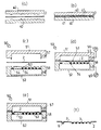
図1はこの発明の一つの実施形態を示し、押釦スイッチ用キートップ部材10は文字、記号、絵柄などの表示部1が印刷された熱可塑性樹脂シート2(上側樹脂シート)に押釦スイッチのキートップ外形形状にあわせた凸部3を成形し、該凸部3の内側に直接または接着剤(図示せず)を介して光硬化性樹脂製の充填物5を固着配備して押釦スイッチ用キートップ部材10としてある。
なお、図1の例では、前記凸部3が複数つながった形態を図示してあるが、単一のキートップ部材であってもよい。このようなキートップ部材は、各種電子機器に組み込まれるときは、必要に応じて1個または複数の独立したキートップ部材または一部つながった複数のキートップ部材が、電気接点を押圧するための押圧子やゴムカバー部材などと組み合わされて組み込み設置される形態として用いられることになる。
【0012】
また、図2に示すこの発明の他の実施形態では、図1の前記押釦スイッチ用キートップ部材10の下側に、さらに接着剤21を介して他の樹脂シート22(下側樹脂シート)を固着配備し、前記押釦スイッチ用キートップ部材を上下の樹脂シートで包み込んだ構成とした。
この場合、前記押釦スイッチ用キートップ部材の下側に固着配備する樹脂シート22に、前記上側樹脂シート2に印刷された表示部1と異なる表示部(図示せず)を印刷することもできる。
さらに、図3の実施形態の押釦スイッチ用キートップ部材10では、押釦スイッチ用キートップ部材10の下側に固着配備される樹脂シート22に電気接点を押圧するための微少突起23が下方に突設され、この下方向に向かった微少突起23が、電気接点を押圧する押圧子の役目をする形態にしたものである。
この場合、光硬化性樹脂製の充填物5に一体または別個体で凸部を設けて、該凸部を覆って、樹脂シート22を固着配備して突起とし電気接点を押圧する押圧子とすることもできる。
【0013】
次に、これら実施形態での押釦スイッチ用キートップ部材を製造する方法について説明すると、表示部1のある上側樹脂シート2の材質は、基本的には熱可塑性樹脂シートであればどの様なものでもよいが、その印刷性と前記凸部3の成形性を考慮すると、ポリエステル系樹脂、アクリル系樹脂、スチレン系樹脂、オレフィン系樹脂、ポリカーボネート系樹脂、ABS樹脂、ポリプロピレン系樹脂、ポリアリレート系樹脂、塩化ビニル樹脂およびそれらの変性ポリマー、アロイ配合物などの熱可塑性樹脂シートが使用される。
具体的には、ポリエチレンテレフタレート、ポリエチレンナフタレート、ポリカーボネート、ポリプロピレン、ポリアクリル酸エステル、ポリスチレン、ポリ塩化ビニル等が例示され、無色透明或いは有色透明もしくは半透明の樹脂シートを用いる。この樹脂シートの厚みは10μmから500μm程度とし、樹脂シートの片面または両面に文字、記号、絵柄などの表示部1の印刷が施される。
この印刷方式、インクの種類などは、特に限定するものではないが、スクリーン印刷、オフセット印刷、グラビア印刷、パッド印刷、熱転写印刷、インクジェット印刷、昇華型印刷等の印刷法などが用いられ、それに適したインクが用いられるが、より複雑で意匠性豊かな印刷を簡易に施すために電子式印刷機である溶融型熱転写プリンター、昇華型熱転写プリンター、インクジェット方式プリンター、トナー転写型プリンターなども用いるのがよい。即ち、昇華型熱転写方式或いはトナー電子方式、静電画像方式、レーザー露光熱現像転写方式、インクジェット方式、熱転写方式、加熱発色方式のいずれか少なくとも1種類のプリンタを用いて、例えばシアン、マゼンダ、イエローの3種類等の複数色の微小ドットで光透過性の色彩、図柄、記号からなる表示部1を有するグラフィック印刷層が樹脂シート2に形成されるものである。
また、これらの印刷と、金属蒸着膜、スパッタリング薄膜、転写箔等を組み合わせてラミネートしたり、レーザー加工等の装飾加工も可能である。
前記表示部1の印刷面は、前記上側樹脂シート2の表側、裏側のどちらか、或いは両方でもよいが、この上側樹脂シート2を透明なものとして裏側に表示部1を印刷した方が、印刷面が直接表にでないので、文字などの耐磨耗性については良好である。即ち、透明の樹脂シートであれば印刷を裏面に施し、印刷面を凸部3の内面にすることによって、キーボード使用中の印刷表示部の磨耗を確実に防ぐことが可能である。さらに、多彩な意匠とするために印刷された樹脂シート2と銀箔(図示せず)をラミネートして、メタリック装飾としたり、抜き文字を印刷して文字照光とすることも可能である。また樹脂シート2の耐磨耗性、耐擦傷性を向上させるために樹脂シートの表面にアクリル系、シリコーン系、メラミン系などのハードコート処理を施すこともできる。
印刷位置は、前記凸部3の天面部分に当たる領域はもちろん必要であれば、その外周、即ち、凸部3の側面に当たる部分にも印刷を施しておくことができる。さらに上側樹脂シート2は、複数枚の同一種類または異種類の樹脂シートがラミネートされた構造であってもよく、熱特性、加工性、印刷特性や意匠性などによって適時選択される。
【0014】
また必要に応じて、これらの印刷の印刷適正を高めるために上側樹脂シート2の印刷面には適切な下処理が施される。例えば、印刷方法の適性に応じて、印刷インクの受容層、たとえば昇華型熱転写印刷ならば、塩化ビニル系、酢酸ビニル系またはポリエステル系のコーティング層を形成しておけばよく、インクジェット印刷ならば水溶性のインクを固着させるための吸水層を形成しておけばよい。更に、密着性を改善するためにコロナ放電、プラズマ処理、UV(紫外線照射)処理、プライマー処理等の下処理を施すことが任意にできる。
【0015】
次に、表示部1が印刷された上側樹脂シート2に、必要とするキートップの外形形状にあわせて凸形状となる凸部3に成形する成形方法としては、圧空真空成形が用いられる。これらの成形方法を図4の工程順に従った例で詳しく説明すると、図4a、図4bは、複数の表示部1が印刷されている熱可塑性樹脂シートの上側樹脂シート2を加熱する工程を示し、図4aのようにヒータで加熱された金型40の間に上側樹脂シート2が挿入され、図4bに示すように加熱金型40で上側樹脂シート2を挟み込んで加熱される。
このとき加熱用の金型40は、上側樹脂シート2の材質に合わせてシートが軟化する所定の温度に加熱されている。加熱する温度は樹脂シートの素材によって適宜に決められるが、おおむね100℃から250℃程度の温度範囲とされる。このとき加熱され、軟化した上側樹脂シート2は、次の圧空真空成形工程で引き延ばされて凸部3ができるが、上側樹脂シート2全体を加熱すると、凸部の天面、即ちキートップの天面となるべき部分も引き延ばされ、そこに印刷されている文字や図形を変形してしまうし、複数の凸部を同時に成形するとそれぞれの凸部にくるべき印刷の位置がずれてしまうので、凸部の天面となるべき部分以外を加熱する部分加熱を行なう。
このために加熱金型40には、上側樹脂シート2の凸部状に形成される部分、いわゆるキートップ天面となる部分に対応する位置に凹み41が形成されており、この凹み41が空気断熱層となって、上側樹脂シート2の凸部天面となるべき部分に直接熱が伝わらないようにして、部分加熱を実現させている。
この場合、考慮すべき点は、凸部の天面となるべき部分の温度を比較的低めに保ち、それ以外の部分を十分に加熱して軟化させることであり、前記凹み41の代わりに冷却された金型を使用することで部分加熱する方法を採用してもよい。前記上側樹脂シート2を加熱する温度は、シートの材質よって決められるが、一般的には、100℃から250℃程度、好ましくは120℃から200℃の範囲で、樹脂の軟化する温度とし、かつ凸部の天面となる部分はこれより約20℃程度以上低めの温度に設定するのがよい。
【0016】
このように部分加熱された上側樹脂シート2は、圧空真空成形の場合、図4cに示す圧空真空成形用の金型50に導入される。この成形金型50は、上金型51と下金型52の上下二枚の金型で構成されており、軟化した上側樹脂シート2を冷却固化できるように前記金型40より低い所定の温度に保たれている。そして図4dに示すように上側樹脂シート2を前記上金型51と下金型52とで挟み、上金型51はエア孔57を介してエアポンプ56に接続され、この上金型51からは成形用の圧空がかけられる。空気の圧力は、樹脂シートの成形性に合わせて調整されるが、おおむね1〜20kg/cm2 の圧力とすることが多い。また、下金型52には、上側樹脂シート2を凸状に引き延ばすための突起53が配置されている。そして該突起53の周囲には、上側樹脂シートの下側の空気を排気するための微少な貫通孔54が下金型52に複数個配置されていて、かつ排気効果を上げるために下金型52は真空排気孔58を介して真空ポンプ55に接続してある。
部分加熱された上側樹脂シート2は、上金型51と下金型52との金型50で挟み込まれながら上からは圧空の力で、かつ下からは真空の力で変形され、図4cのように下金型52の突起53に沿って変形して上側樹脂シート2上に凸部3が成形される。
この時、凸部の天面となるべき部分の温度を比較的低めに保ってあるので、上側樹脂シート2が余り加熱されないし、図4eに示すように金型50で上側樹脂シート2を挟み込む位置と、突起53の天面の高さを略同一とし、それ以外の部分を下方向に絞るように設計しておけば、実質的に上側樹脂シート2の凸部の天面部分は全く引き延ばされずに所定の成形ができる。
ここで前記下金型52に接触した上側樹脂シート2は、下金型52で冷却され、固化して上側樹脂シート2上に凸部3が成形される。
このように、複数の凸部3が成形されたその外周には不要部分の縁取り部6もある上側樹脂シート2を前記金型50から取り出すと、図4fに示すような、前記凸部3が複数つながった形態のものとなっている。
即ち、この凸部3が成形された上側樹脂シート2を金型50から取り出したのち、上側樹脂シート2の凸部3の天面部分及び側面部分を残して、不必要な部分(底面部分及びその周縁部分)を切除して前記充填物5が入れられる凹部のあるキートップ外殻とする(図4f)。場合によっては凸部3の内側に充填物5を充填したのちに不必要な部分を切除することでもよい。
【0017】
なお、前記凸部3の成型時には、上側樹脂シート2の熱可塑性樹脂シート全体を引き伸ばして成形するのではなく、選択的に所定の部分を引き伸ばして成形することが配慮される。例えば本発明のキートップ部材の場合、印刷樹脂シートのキートップの天面にあたる部分には所定の文字、数字、記号、図柄などの表示部1の意匠が印刷されているので、上側樹脂シート2の凸部3の成形において、上側樹脂シート2の凸部3の天面となるべき部分を固定し、凸部3の側面、底面部となるべき部分だけを主として引き伸ばし、全体として凸部を成形することが配慮される。これには、図4のように圧空と真空を併用した成形工程を用いて、キートップの天面となるべき部分を固定して他の部分を引き伸ばして圧空真空成形するのがよい。
【0018】
即ち、図4dにおいて上側樹脂シート2のうちキートップ形状の凸部3の天面部分となる部分は、成形金型50が締まると同時に金型で固定され、必要に応じてR形状をつけられるものの実質的に引き伸ばされないようになっている。次に図4eで真空と圧空を金型内に操作すると、上側樹脂シート2はその圧力で引き伸ばされ、金型に沿って変形する。そして、成形金型50によって上側樹脂シート2が冷却されキートップの凸部形状となるのである。このとき、樹脂シートの引き伸ばされる部分はキートップの側面部分と底面部分であり、実質的に引き伸ばされない天面部分に施された印刷は、形状が変化することもなく、厚みが薄くなることもなく、印刷品位が良好に保持される。側面部分と底面部分の引き伸ばされる割合はキートップの寸法によって異なるが、おおむね初期の樹脂シート厚みの30%から80%程度となる。
以上のようにシートの天面となるべき部分の伸び変形を抑え、他の部分を引き伸ばすことで印刷表示部1が変形したり、見苦しいものになったりすることもなく、印刷厚みが薄くなって、文字照光の場合の光の遮蔽性が損なわれることもなく、また延びにくい銀インクや銀箔を使用した意匠の場合でも亀裂やひび割れもなく良好な外観品位のキートップを得ることが可能である。もちろん、引き伸ばされた部分と引き伸ばされていない部分の境界を滑らかにするために、印刷に支障のない範囲内でキートップの天面になるべき部分の固定力を調整して段階的に引き伸ばすことも可能であるし、天面の伸びを抑える方法として金型で固定するのではなく、樹脂シートの加熱時に伸ばしたい部分だけを加熱するといった方法をとることも可能である。
このように圧空真空成形は、必要とする設備がシート加熱用のヒーターと、凹部を形成した簡単な成形金型のみなので非常に安価な設備で成形が可能で、その生産性も射出成形に比較して数倍の生産性を得ることができる。
【0019】
なお、圧空真空成形の場合に限らず、あらかじめ複数の表示部を設けた熱可塑性樹脂シートを真空成形、圧空成形、圧縮成形から選択される一つの成形方法を用いて、押釦スイッチのキートップ外形形状に合わせた凸部を成形することもできる。例えば、真空成形であれば、金型の凹部に設けられた真空孔からエアを排除して凹部を真空にすることによって、加熱されて軟化している印刷樹脂シートの上側樹脂シート2を変形させ凹部に密着させて凸部形状を作ればよい。また、圧空成形であれば反対に印刷樹脂シートの側からエア圧力を利用して印刷樹脂シートを変形させて金型の凹部に密着させる。このとき成形金型は冷却されているので軟化している上側樹脂シート2は、成形金型の凹部と密着すると同時に冷却固化し、印刷樹脂シートに所望の凸部形状が成形されるのである。さらに、圧縮成形法でも、印刷樹脂シート2を軟化する温度に加熱した後に、所定の凹部と凸部を持った2枚の冷却された成形金型で挟みこみ、該成形金型を閉める圧力でキートップ形状の凸部を成形する方法である。このように圧縮成形では、1対の凹部と凸部の金型なので、非常に安価な設備で成形が可能で、その生産性も射出成形に比較し数倍の生産性を得ることができる。
【0020】
さらに前記実施形態で用いられる光硬化性樹脂としては、固化前は液状でこれに紫外線や可視光線などを照射して固化する樹脂で、例えば、アクリル系光硬化樹脂、メタクリル系光硬化樹脂、不飽和ポリエステル系光硬化樹脂、スチレン系光硬化樹脂、ウレタン系光硬化樹脂、ジアリルフタレート系光硬化樹脂などや、これらの混合物が例示されるが、これらに必要に応じ硬化剤、光開始反応剤、触媒、粘度調整剤、反応速度調整材料、着色剤、充填剤、増量剤などを添加して用いてもよい。
そして、これらの紫外線硬化樹脂を所定の形状の金型に注入し、紫外線を照射して硬化させ、これを金型から取り出して、接着剤を用いて前記印刷樹脂シート2の凸部3の内側に張り付けてもよいのであるが、ここではさらに合理的な実施形態を図5で説明する。
熱可塑性樹脂シートにキートップ成形工程の圧空真空成形によってキートップ外形形状にあわせた凸部3を成形した上側樹脂シート2は、不要部分である外周の縁取り部を切り取って凸部3が下になるように裏返しておき(図5a)、この凸部3の中に液体状態の光硬化樹脂30をディスペンサー31などを用いて注入し凸部3の内側を満たす(図5b)。次いで、図5cに示すようにランプ33によって紫外線などの光線32を照射して光硬化樹脂を硬化させ、押釦スイッチ用キートップ部材とする。
この場合、光硬化樹脂は硬化時の収縮が大きいので、必要であれば一度注入して硬化させた後に、収縮分を補う量の光硬化樹脂をもう一度注入して光を照射して光硬化樹脂を硬化させることもできる。
また、光硬化樹脂は、硬化時に強い紫外線を必要とするばかりでなく、それ自体も硬化発熱するので、光硬化の際は必要に応じ印刷樹脂シートの温度が極端に高くならないように冷却機構(図示せず)を設けてもよい。
【0021】
このように構成された押釦スイッチ用キートップ部材は、上部を様々に装飾、印刷された樹脂シートで覆われており、意匠性に富むばかりでなく、その装飾、や印刷は、透明樹脂シートの内側に施されているので、印刷の耐磨耗性や耐擦傷性に高い性能を発揮するし、その製造も高い金型を使用することなく、安価な真空成形用金型を使って瞬時に形作られ、さらにキートップの天面は殆ど変形させないので、印刷位置が変形したり、ずれたりすることもなく高品位な押釦スイッチ用キートップ部材とすることができる。
また、この押釦スイッチ用キートップ部材の上側樹脂シートは、キートップの天面及び側面を覆っているので、天面だけの印刷意匠ではなく、側面や天面と側面との境界部分など、印刷の難しい部分にも簡単に印刷や 着色、装飾を施すことができる。さらに、一般にはインジェクション成形で作られるキートップ部分も、この発明では、液体状態の光硬化樹脂を注入して硬化させることで作るので、高温、高圧力樹脂を扱う必要がなく、大がかりな装置や高価な成形金型を使用することがなく安価に大量に生産することができる。
【0022】
さらに、作られた前記押釦スイッチ用キートップ部材は、複数のキートップが一枚の樹脂シート上に成形されているが、これをそのまま使用してもよいし、印刷された上側樹脂シートの一部分を打ち抜くなどして不要部分を取り除いて利用することもでき、キートップを個々に切り取りは配置してもよい。一般にはこれらのキートップの下に電気接点を押圧する突起物を持つゴムシート部材を配置し、その下にシート状のフイルム接点や電気基板を配置し、携帯電話機や計測器、リモコンなどの各種キーボードとして組み込まれて用いられる。
【0023】
図2に示す実施形態で用いられる下側樹脂シート22としては、押釦スイッチ用キートップ部材10の下側に接着剤21で固着配備して、上側樹脂シート2とで押釦スイッチ用キートップ部材を包み込む形態とすることによって、凸部3に充填された光硬化性樹脂を封入し、キートップ部材としての信頼性や寸法安定性、強度、剛性、などを高めることができるし、光硬化性樹脂の充填物が剥離脱落したり、光硬化性樹脂と上側樹脂シート2の間のゴミや異物、水蒸気などの浸入を防ぎ、信頼性の高いものとすることができる。
更には、この下側樹脂シート22を着色や印刷されたものや金属光沢を持ったものとし、上側樹脂シート2の印刷を半透明とすれば、キートップに入った光が下側樹脂シート22で反射し、光沢や着色キートップの意匠を作ることができる。例えば、上側樹脂シート2に半透明青色のインクで、文字、数字などを印刷しておき、下側樹脂シート22の色を赤色に着色しておけば、キートップ全体としては、赤色となるし、そのキートップの天面は青色の文字、数字が浮かんでみえるような独特な意匠を作りだすことができる。
そして、前記下側樹脂シート22は、一般に用いられる熱可塑性樹脂シートを選べばよいが、取扱や印刷適正などを考慮すると、ポリエステル系樹脂、アクリル系樹脂、スチレン系樹脂、オレフィン系樹脂、ポリカーボネート系樹脂、ABS樹脂、ポリプロピレン系樹脂、ポリアクリレート系樹脂などの熱可塑性樹脂シートが使用される。
具体的にはポリエチレンテレフタレート、ポリエチレンナフタレート、ポリカーボネート、ポリプロピレン、ポリアクリル酸エステル、ポリスチレン、ポリ塩化ビニル等が例示され、無色透明或いは有色透明もしくは半透明の樹脂シートを用いる。この樹脂シートの厚みは15μmから500μm程度とし、樹脂シートの片面または両面に文字、記号、絵柄などの表示部1の印刷が施される。
この場合、前記押釦スイッチ用キートップ部材の下側に固着配備する下側樹脂シート22に、前記上側樹脂シート2に印刷された表示部1と異なる表示部を印刷することもできる。
この印刷には、印刷方式、インクの種類などは、特に限定するものではないが、スクリーン印刷、オフセット印刷、グラビア印刷、パッド印刷、熱転写印刷、インクジェット印刷、昇華型熱転写印刷などの印刷法などが用いられ、それに適したインクが用いられる。また、これらの印刷と金属蒸着膜、スタッパリング薄膜、転写箔などを組み合わせラミネートしたり、レーザー加工等の装飾加工も可能であり、また、複数枚の同一種類または異種類の樹脂シートがラミネートされた構造であってもよく、熱特性、加工性、印刷特性や意匠性などによって適宜選択される。
【0024】
上側樹脂シート2と下側樹脂シート22とで押釦スイッチ用キートップ部材を包み込んだ構成とした場合、上側樹脂シート2に表示部1を印刷した印刷樹脂シートを用いた場合の形態では、下側樹脂シート22としては無地樹脂シート(透明、或いは着色または無模様シート)や、表示部のある印刷樹脂シートのいずれかが選んで用いられる。
また、前記凸部3を成形する上側樹脂シート2に無地樹脂シートを用いた場合の形態では、下側樹脂シート22は表示部を印刷した形態のものを張り合わせて押釦スイッチ用キートップ部材を構成してある。
いずれにしても、透明なキートップを通してキートップに文字、記号、絵柄の表示部を認識できる意匠のキートップ部材とすることもできる。
【0025】
上側樹脂シート2や下側樹脂シート22と、凸部3の内側に充填される充填物5との接着剤21としては、上側樹脂シート2や下側樹脂シート22と、光硬化性樹脂との接着性や作業性を考慮して選択されるが、特に下側樹脂シート22に印刷や着色を施す場合には、透明性が要求されるので、透明接着剤を用い、例えばアクリル系接着剤、ポリエステル系接着剤、シリコーン系接着剤、ウレタン系接着剤などから選択して用いるのが望ましい。さらにこの接着剤としては、溶剤揮発型、二液硬化型、光硬化型などがあるが、短時間に確実に接着することを考慮すると、光硬化型を用いて接着するのがよい。
なお下側樹脂シート22と光硬化性樹脂との接着方法には、特に限定されるものではないが、一例をあげると、紫外線硬化型の低粘度タイプの接着剤をディスペンサーを用いて塗布し、ここに下側樹脂シート22を密着させ、直ちに紫外線を照射して接着固化することが好適例として例示できる。
【0026】
このように製造された押釦スイッチ用キートップ部材は、上側樹脂シート2が、キートップの凸部状になっておりその中に硬化した光硬化性樹脂が配置され、その下に下側樹脂シート22が接着配置されている。
この上側樹脂シート2は、様々な文字、記号、装飾が予め施されたシートで、キートップ樹脂に直接印刷したものよりも複雑な意匠を形成することができるし、必要なら凸部3の側面にも印刷や装飾を簡単に配置することができる。
また、表示部の印刷は上側樹脂シート2の裏面にすると、印刷面が直接表面に露出しないので、印刷の保護にもなるし、光硬化性樹脂も傷や破損を生じることがなく安全に保護することができる。
さらには下側樹脂シート22で光硬化性樹脂を包み込む形態となっているので、キートップ自体の強度も強靱なものなり、上側樹脂シート2と光硬化性樹脂との界面に汚れや水分、水蒸気、腐蝕性ガスなどが浸入しないで、長期にわたって印刷や接着力を保持することができる高信頼性のある押釦スイッチ用キートップ部材とすることができる。
【0027】
また、光透過性樹脂を実質透明な状態の配合とし、下側樹脂シート22にも印刷や着色、光沢装飾などを施しておけば、キートップの凸部天面、側面、裏面すべてに多様なデザイン、意匠を持つ押釦スイッチ用キートップ部材とすることができる。たとえば、上下樹脂シートの濃度と色合いを選ぶことによって、昼間は反射光による上側樹脂シート2の模様を見せ、夜間は下からの透過光によって下側樹脂シート22の印刷や色合いを強く見せる形態としたり、下側樹脂シート22を高輝度に光が反射する金属箔やホログラムシート等をラミネートした構造としておけば、上側樹脂シート2の印刷が、遠近感が強く見えるように感じさせるデザインとすることが可能となる。
その上、光硬化性樹脂に着色したり、光反射性のある細かな充填剤を配合したり、鱗片状の充填剤、パール調の充填剤を配合したりすることで、様々な装飾が簡易にできることになる。
いずれにしても、この押釦スイッチ用キートップ部材は、キートップの天面、側面、裏面、さには凸部中身の樹脂までも簡単に装飾可能で、様々な意匠が簡単に作り出せ、長期にわって信頼性のあるキートップとすることができる。
【0028】
図3の実施形態では、電気接点を押圧するための微少突起23を押釦スイッチ用キートップ部材10の下側に突設したものであるが、押釦スイッチ用キートップ部材10の下側に接着剤21を介して固着配備される下側樹脂シート22に金型中で絞り加工して微少突起23を設けてあり、必要に応じ絞り加工した凸状の内側に接着剤21を充填したり、別部材の貼付け、或いは光硬化性樹脂の凸部を包んで微少突起23を備えてもよく、この下方向に向かった微少突起23が、電気接点を押圧する押圧子の役目をする形態にしたものである。
この微少突起23は、直径0.3〜3.0mm程度とし、高さは電子機器やキーボードの高さなどによって決められるが、おおむね0.5〜5.0mm程度とされることが多い。
そして、前記微少突起23を形成するには、図3例では熱可塑性樹脂シートの下側樹脂シート22を加熱加圧することで微少の突起23を形成する。この加熱加圧する方法としては、金型で圧縮するか、圧空力や真空力で成形するかなどが例示されれるが、微少突起23の形状によって選ばれる。例えば、下側樹脂シート22を樹脂シートの熱軟化点付近の温度に加熱しておき、これを凸部を形成してある真空成形金型の中に挿入し、真空力で樹脂シートを金型に密着させることで凸状の微少突起23を形成する。
【0029】
なお、この微少突起23を形成した下側樹脂シート22を前記押釦スイッチ用キートップ部材10の下側に前述同様の方法で接着剤21で接着するのであるが、下側樹脂シート22に成形された微少突起23の凸状の内側も接着剤21で十分満たされていることが望ましい。このように微少突起23の内側も接着剤21で十分満たされていることによって押圧された時に、微少突起23の変形するのを防ぐことができる。
また、この例では、ゴムシート部材を必要とすることなくキートップ部材を接点シートの上に直接配置組み込みできるので、部品点数を少なくした合理的な押釦スイッチ機器とすることができる。
【0030】
いずれにしても、本発明による押釦スイッチ用キートップ部材10は、これを携帯電話や電子機器用キーボードユニットにそのまま組み込んでキートップ部材として利用しても良いし、複数のキートップをゴムカバー部材の所定の位置に固定した集合体として利用することも可能である。このようにゴムカバー部材の上に複数のキートップを配置固定することで、全体としてはキートップ部材を1枚のキーボードシートとすることによって、電子機器用キーボードユニットへの組み込みが簡単なものとなるし、ゴムカバー部材の形状、厚みなどを変更することで、個々のキートップの高さを変更することもできるし、ゴムの柔軟性を利用して、電子機器の外側ケースの曲面形状などにも組み込めるキーボードシートとすることができる。
【0031】
この場合、用いられるゴムカバー部材としては、一般にシリコーンゴム、ウレタンゴム、EPDMゴムなどまたは各種熱可塑性エラストマーなどによって作られており、その成形方法は圧縮成形、射出成形、トランスファー成形などの方法が採用される。キートップ部材の配置固定方法としては嵌合、接着剤、粘着剤などを使用すればよいが、好ましくはキートップ部材が脱落、剥離しないよう接着剤を用いて強固に接着されることが望ましい。
【0032】
【実施例】
次に、この発明の実施例を説明する。
【0033】
実施例1
厚さ0.2mmのアクリルシート(三菱レイヨン(株)製:商品名アクリプレン)の片側に、縦方向、横方向それぞれ複数本の線を1.0mm間隔、0.2mmの線幅でスクリーン印刷した樹脂シートと、厚さ0.2mmポリエステルシート(東洋紡(株)製:商品名PETMAX)とを印刷面を挟むようにしてドライラミ接着剤(日立化成ボリマー(株)製:商品名ハイポン7662)によって、100゜C、2kg/cm2 で10秒間、加熱加圧することによって張り合わせて、表示部のある印刷樹脂シート(以下、上側樹脂シートという)を得た。
そして、この上側樹脂シートに複数の所定形状の押釦部を形成するために押釦スイッチのキートップ投影面に相当する形状で、且つ同じ面積で深さ方向に5mm彫り込んだ加熱金型(図4a)と、キートップを凸状に賦形するための冷却用圧空真空成形金型(図4c)とを用いて行った。
前記アクリルシートを上金型側に、ポリエステルシートを下金型側になるように上側樹脂シートを配置し、加熱金型を190゜C、冷却用圧空真空成形金型を30゜Cに温度調節し、上側樹脂シートを加熱金型で1秒間、加熱し、続いて1秒間後に圧空真空成形金型の間に加熱された上側樹脂シートを挿入し、上金型の圧空エア孔より5kg/cm2 の空気圧と、80 Toorの真空圧を同時にかけて圧空真空成形し、3秒間の冷却の後に、圧空真空成形金型を開いて、凸形状に賦形された押釦スイッチ用シート(以下、賦形シートという)を得た。
次いで、賦形シートの凸部が下になるように治具に設置し、高さ3mmのキートップ凸部の内側に紫外線硬化性樹脂(ノガワケミカル(株)製:商品名UV130L)をエアディスペンサーにて凹部に注入して満たし、高圧水銀ランプ120W/m、照射距離15cm、照射時間15秒で紫外線照射して硬化させた。このようにして硬化させた凹部は硬化収縮によって約0.5mm凹んでいるため、さらに前記紫外線硬化性樹脂をエアディスペンサーにて硬化物凹部に注入して満たし、高圧水銀ランプ120W/m、照射距離15cm、照射時間5秒で紫外線照射して硬化させることで、請求項1に該当する押釦スイッチ用キートップ部材を得た。
この方法によって得た押釦スイッチ用キートップ部材は、キートップ天面に形成した1mm間隔の線幅0.2mmの格子点間距離は最大で1.02mmであり、天面全体において歪みが2%しかなく、高品位な押釦スイッチ用キートップ部材を得ることができた。
【0034】
実施例2
厚さ0.2mmのポリアリレートシート(ユニチカ(株)製:商品名Uポリマー)の片側に、押釦スイッチ用の押釦毎に光線透過率50%のインク濃度で白色の文字、記号、絵柄をスクリーン印刷し、さらにこの文字、記号、絵柄の周りを遮光性の黒色で切れ目なくスクリーン印刷した樹脂シートと、厚さ0.2mmのコポリエステルシート(イーストマンケミカル(株)製:商品名Eastar PETG6763)とを前記印刷面を挟み込むようにしてドライラミ接着剤(日立化成ポリマー(株)製:商品名ハイポン790−1)によって100℃、5kg/cm2 で10秒間、加熱加圧することでラミネートし、表示部のある印刷樹脂シート(以下、上側樹脂シートという)を得た。
この上側樹脂シートを用いて、実施例1と同様にして賦形シートを成形し、つづいて賦形シートの凸部が下になるように治具に設置し、高さ3mmのキートップ凸部の内側に紫外線硬化性樹脂(ノガワケミカル(株)製:商品名UV130L)をエアディスペンサーにて凹部に注入して満たし、高圧水銀ランプ120W/m、照射距離15cm、照射時間15秒で紫外線照射して硬化させてキートップ部材とした。
該キートップ部材にさらに紫外線硬化性接着剤(ノガワケミカル(株)製:商品名UV250H)をエアディスペンサーにて塗布し、該キートップ部材全体を覆う面積で、且つ厚さ0.2mmの透明ポリエステルシート(三菱化学(株)製:商品名ノバクリアー)で張り合わせ、透明ポリエステルシート側から高圧水銀ランプ120W/m、照射距離15cm、照射時間5秒で、紫外線照射して接着硬化させて、各キートップ部の周囲に不要な樹脂シート部がついた状態の押釦スイッチ用キートップ基材を得た。次いで押釦スイッチ用キートップ基材の不要な樹脂シート部を打抜治具によって打ち抜いて所望の押釦スイッチ用キートップ部材を得た。
このようにして得た押釦スイッチ用キートップ部材は、反射光で文字や絵柄が認識できることはもちろん、該キートップ部材の裏側から光を照射することで、暗いところでも文字を光らせて認識させることができる、いわゆる文字照光型を容易に得ることができた。また、キートップの側面、キートップ間にも遮光性の黒色が施され、該キートップ部材を筐体に組み込んだ場合の光漏れを完全に防止することができた。さらに、該押釦スイッチ用キートップ部材全体を覆う面積の0.2mm厚みの透明ポリエステルシートを配置したことで、光硬化性樹脂と印刷シートとの間にゴミや異物が入る心配がなく、また高温高湿環境下(温度60度、相対湿度95%、240時間)での水蒸気などの侵入も認められず、高信頼性のキートップ部材を得ることができた。
【0035】
実施例3
厚さ0.2mmのポリアリレートシート(ユニチカ(株)製:商品名Uポリマー)の片側に赤色で全面にスクリーン印刷した樹脂シート(以下、下側樹脂シートという)を予め準備しておいた。
一方、厚さ0.2mmのアクリルシート(三菱レイヨン(株)製:商品名アクリプレン)の片側に、押釦スイッチ用の押釦毎に光線通過率50%のインク濃度で青色の文字、記号、絵柄を熱転写プリンタ(セイコーインスツルメンツ(株)製:商品名Color Point 1635PSJ)で熱転写印刷した樹脂シートを得た(以下印刷シートという)。
この印刷シートに厚さ0.2mmのポリエステルシート(イーストマンケミカル(株)製:商品名Eastar PETG 6763)を印刷面を挟み込むようにしてドライラミ接着剤(日立化成ポリマー(株)製:商品名ハイポン790−1)によって100℃、2kg/cm2 で10秒間、加熱加圧することでラミネートし、表示部のある印刷樹脂シート(以下、上側樹脂シートという)とした。
実施例2と同様にして、この上側樹脂シートを圧空真空成形することで得たキートップ部材の各キートップ部に、さらに紫外線硬化性接着剤(ノガワケミカル(株)製:商品名UV250H)をエアディスペンサーにて塗布し、該キートップ部材と前記上側樹脂シートと前記下側樹脂シートを張り合わせ、キートップ天面側から高圧水銀ランプ120W/m、照射距離15cm、照射時間5秒で紫外線照射して接着硬化させてキートップ部材を得た。
このキートップ部材を各キートップ毎に切り取り、これらを電気接点を押圧する突起物を持つ透光性のシリコーンゴムシート(信越化学(株)製:商品名KE−581−U)上に透光性を有する粘着剤(日立化成ポリマー(株)製:商品名11−583)によって張り付けて、押釦スイッチ用キートップ部材を得た。
このようにして得た押釦スイッチ用キートップ部材は、キートップ全体としては下部の赤い透明キートップの天面に、青い文字、記号、絵柄が浮かんで見えるという独特の意匠が得られた。
またゴムシートに張り付けることで、電気基板とキートップ毎の高さが極端に異なる場合にも、ゴムシートの高さをキートップ毎に設定しておけば容易に対応することができる利点を有していた。
【0036】
実施例4
厚さ0.2mmの透明アクリロニトリルシート(三井化学(株)製:商品名ゼクロン)を用いて、実施例1で示したキートップ部材と同様の圧空真空成形法で、直径1.0mm、高さ0.5mmの凸形状に賦形された電気接点を押圧する押圧部のある樹脂シート(以下、下側樹脂シートという)を予め準備しておいた。次に、厚さ0.2mmの透明アクリロニトリルシート(三井化学(株):商品名ゼクロン)の片側に、押釦スイッチ用の押釦毎に光線透過率50%のインク濃度で白色の文字、記号、絵柄をスクリーン印刷し、つぎにこの文字、記号、絵柄の周りを遮光性の黒色で切れ目なくスクリーン印刷した樹脂シートと、厚さ0.2mmの透明アクリロニトリルシート(三井化学(株)製:商品名ゼクロン)とを印刷面を挟み込むようにしてドライラミ接着剤(日立化成ポリマー(株)製:商品名ハイボン790−1)によって100℃、5kg/cm2 で10秒間、加熱加圧することでラミネートし、表示部のある印刷樹脂シート(以下、上側樹脂シートという)を得た。
実施例1と同様に、この上側樹脂シートを圧空真空成形して得たキートップ部材の各キートップ部に、さらに紫外線硬化性樹脂(ノガワケミカル(株)製:商品名UV250H)をエアディスペンサーにて塗布し、これと前記下側樹脂シートを張り合わせ、押圧部側から高圧水銀ランプ120W/m、照射距離15cm、照射時間5秒で紫外線照射して接着硬化させ、押釦スイッチ用キートップ部材を得た。
このようにして得た押釦スイッチ用キートップ部材は、キートップ天面に様々な文字、記号、絵柄が配置され、且つすでに凸形状に賦形された電気的接点を押圧する部分を有するため、ゴムに貼り付けた場合に比べて薄く仕上げられ、この状態で携帯電話などの筐体に組み込める利点を有していた。
【0037】
実施例5
市販の厚さ0.125mmのポリエステルシート(日本ビクター(株)製:クリアレシーバー JP−D304F)の片側(インク受容層側)に、押釦スイッチ用の押釦毎に青色の文字、記号、絵柄を昇華型熱転写プリンター(日本ビクター(株)製:Trueprint 3500PS)を用い熱転写印刷した樹脂シート(以下、下側樹脂シートという)を予め準備しておいた。
次に、厚さ0.2mmの透明アクリロニトリルシート(三井化学(株)製:商品名ゼクロン)を用いて、実施例1で示したキートップ部材と同様の圧空真空成形法で、凸形状に賦形された押釦スイッチ用シートを得た(以下、賦形シートという)。
続いて、賦形シートの凸部が下になるように治具に設置し、高さ3mmのキートップ凸部の内側に紫外線硬化性樹脂(ノガワケミカル(株)製:商品名UV130L)をエアディスペンサーにて凹部に注入して満たし、高圧水銀ランプ120W/m、照射距離15cm、照射時間15秒で紫外線照射して硬化させた。さらに紫外線硬化性接着剤(ノガワケミカル(株)製:商品名UV145B)をエアディスペンサーにて塗布して前記賦形シートと前記下側樹脂シートを張り合わせ、キートップ天面側から高圧水銀ランプ120W/m、照射距離15cm、照射時間10秒で紫外線照射して接着硬化させ、押釦スイッチ用キートップ部材を得た。
このようにして得た押釦スイッチ用キートップ部材は、透明な光硬化性樹脂キートップの天面、側面部分が透明アクリロニトリルシートによって覆われており、透明なキートップを通してキートップ底面に印刷されている文字、記号、絵柄を認識することのできる意匠のキートップ部材が得られた。
この方法によれば、射出成形などによって成形された個々の透明キートップと印刷シートを接着剤などで張り合わせる場合に比べ、キートップと底面に固着された下側樹脂シートの位置合わせが容易であり、硬化途中で位置ずれすることなく接着させることが可能であった。また張り合わせに使用する接着剤は、賦形シートと下側樹脂シートとの間で硬化することから、外にはみ出した接着剤の臭気やべたつきが全くなく、はみ出し量を気にすることなく作業が行えることから、効率よく安価に大量に生産することができた。
【0038】
次に、以上の実施例と実施例1で部分加熱をしない場合の次の比較例でその有用性が確認できた。
【比較例】
実施例1と同様にして縦横線で格子状に印刷した印刷シートを得た。この印刷シートのキートップ天面を含む部材全体を加熱する加熱金型と、キートップを凸状に賦形するための圧空真空成形用金型を図4cのように上下に真空成形機に設置し、上金型側にアクリルシートを、また下金型側にポリエステルシートとなるように印刷シートを配置した。つぎに加熱金型を170℃、圧空真空成形用金型を30℃に温度調節し、印刷シートを加熱金型で1秒間加熱し、続いて1秒後に圧空真空成形用金型にて、5kg/cm2 の圧力で圧空真空成形し、凸形状に賦形された押釦スイッチ用シート(以下賦形シート)を得た。
続いて、賦形シートの凸部が下になるように治具に設置し、高さ3mmのキートップ凸部の内側に紫外線硬化性樹脂(ノガワケミカル(株)製:商品名UV130L)をエアディスペンサーにて凹部に注入して満たし、高圧水銀ランプ120W/m、照射距離15cm、照射時間5秒で紫外線照射して硬化させた。このようにして硬化させた凹部は硬化収縮によって約0.5mm凹んでいるため、さらに前記紫外線硬化性樹脂をエアーディスペンサーにて硬化物凹部に注入して満たし、高圧水銀ランプ120W/m、照射距離15cm、照射時間5秒で紫外線照射して硬化させることで、請求項1に該当する押釦スイッチ用キートップ部材を得た。
この方法によって得た押釦スイッチ用キートップ部材は、キートップ天面に形成した1mm間隔の線幅0.2mmの格子点間距離は最大で、1.45mmであり、天面全体において45%の大きな歪みが生じ、原形をとどめないものであった。
【0039】
【発明の効果】
本発明は、表示部が印刷された樹脂シートに、押釦スイッチのキートップ外形形状にあわせた凸部を成形し、この凸部の内側に、直接または接着剤を介して光硬化性樹脂製の充填物を固着配備したことにより、樹脂シートの引っ張りに伴う変形が表示部に生じないため、視認性がよいし、キートップの表示部のデザインにコンピュータを用いたデザインデータが使用でき、デザインの自由度が増し、意匠性に富んだ押釦スイッチ用キートップ部材にでき、その製造コストをも高価な射出成形用金型を用いることなく、安価で簡単に製造でき、その製品も高品位にでき、しかも凸状に成形された印刷樹脂シートで構成されるので、小ロット多品種製造であってもコストを増大させることなく対処できるし、成形品などに印刷する場合に比べ簡単に大量に安価に制作することがてき生産性の大幅な向上を図れる。
また、本発明では、熱可塑性樹脂シートで構成される押釦スイッチ用キートップ部材が上下の樹脂シートで包み込んだ構成としたことで、キートップ側の樹脂フィルムとベース部側の樹脂フィルムの重なり合いによって表示部に立体感のある絵柄、良いクラデーション効果等の独特の外観が得られると共に、光硬化樹脂の硬化に伴う収縮によってもベース面側に凹凸が発生することなく外観上、組込み作業上の不具合もなく、さらに充填物樹脂と樹脂フィルムとの接着性、防水性、防塵性をも向上し、余分な未硬化接着剤などの流れ出しに伴う異臭も押さえ込められ商品価値の高いキートップ部材とし、しかもキートップのクリック感や弾性特性を生かしながら、キートップ部分は充填物の硬さを生かしてキー操作の安定性を確実にし高い耐久性をも得られるものである。
【図面の簡単な説明】
【図1】本発明の実施形態のキートップ部材の拡大断面図である。
【図2】本発明の他の実施形態の拡大縦断面図である。
【図3】本発明のさらに他の実施形態の拡大縦断面図である。
【図4】本発明の上側樹脂シートの製造工程のアルファベット順に示す模式図である。
【図5】本発明のキートップ部材とする製造工程のアルファベット順に示す模式図である。
【符号の説明】
1 表示部
2 樹脂シート(上側樹脂シート)
3 凸部
5 充填物
6 縁取り部
10 押釦スイッチ用キートップ部材
21 接着剤
22 樹脂シート(下側樹脂シート)
23 微少突起
40 加熱金型
41 凹み
50 成形金型
51 上金型
52 下金型
53 突起
54 貫通孔
55 真空ポンプ
56 エアーポンプ[0001]
BACKGROUND OF THE INVENTION
INDUSTRIAL APPLICABILITY The present invention is used as a part for mobile communication devices such as mobile phones and automobile phones, home phones, electronic notebooks, measuring devices, in-vehicle switches, remote controllers, computers, data input devices and switch devices of personal computers, and the like. Key top for pushbutton switchMaterialMore specifically, a key for a push button switch which is excellent in design and durability of a display portion such as a character printed on a sheet or a symbol or a pattern, and can be used for an illuminated push button switch. Top sectionMaterialIt relates to a manufacturing method.
[0002]
[Prior art]
In general, in pushbutton switches such as mobile communication devices such as mobile phones, electronic notebooks, measuring instruments, and remote controllers, a key top member or a cover member on which key tops are arranged is incorporated in a circuit board housed in a device case. The key top member for the push button switch is a key top member formed of a thermoplastic resin into a predetermined shape by injection molding. Widely used. Recently, it has been required to apply various printing designs to the key tops in addition to symbols or designs. For this reason, there is no need to print directly on the key top member, and printing with a wide variety of design features in advance. Is applied to a resin sheet, and is sandwiched in an injection mold for forming a key top on the printed resin sheet, and the printing resin sheet is drawn simultaneously with the key top molding by using the pressure of the injected resin. A key top member for a pushbutton switch is formed by in-mold molding or insert molding of a printed resin sheet.
[0003]
[Problems to be solved by the invention]
Conventionally, in-mold molding or insert molding of a printed resin sheet with such a key top member requires an expensive and special injection mold, and the molding conditions for injection molding are difficult and inferior in productivity. In addition, the selection of materials such as resin is limited, resulting in a costly part. For example, as a mold, a printing resin sheet is inserted into the mold and injection molding is performed, so the printing resin sheet is required to have high heat resistance, and the printing resin sheet is injected for each part to be drawn. A gate must be provided, specifically, at least one gate must be provided for each key top shape, and when molding a plurality of key tops, it becomes a particularly expensive and complicated mold, In addition, many gate injection conditions must be prepared, and high-temperature and high-pressure molten resin for drawing molding of printed resin sheets must be injected, and the temperature and pressure conditions of the resin and mold are precisely controlled. Had to control.
In addition, because of its manufacturing method, the portion of the printed resin sheet that is to be the key top is formed by being stretched by molten resin, so that the preprinted printed resin sheet may be deformed by being stretched. , There was a drawback that the position would be misaligned.
[0004]
The present invention is intended to eliminate these conventional problems, and is a key top member for a pushbutton switch having a printed resin sheet interposed therebetween, which can be manufactured inexpensively and easily without using an expensive injection mold. Moreover, the key top part for pushbutton switches that can make the product remarkably high qualityMaterialA manufacturing method is to be provided.
[0005]
[Means for Solving the Problems]
In order to achieve the above object, a key top member for a pushbutton switch of the present inventionManufacturing methodIsAn upper resin sheet on which a convex portion is formed in accordance with the key top outer shape of the pushbutton switch and the display portion is printed, a filling material fixedly made of a photocurable resin inside the convex portion, and the filling material A method for manufacturing a key top member for a pushbutton switch, which is formed by adhering a lower resin sheet protruding with a microprojection facing the convex portion,
When preparing a thermoplastic resin sheet on which the display parts of the key tops of the pushbutton switch are printed, and forming a plurality of protrusions on the thermoplastic resin sheet to match the keytop outer shape of the pushbutton switch, After the thermoplastic resin sheet is heated from both sides with the engraved heating die, the thermoplastic resin sheet is cooled and solidified by vacuum forming at a temperature lower than the temperature of the heating die. The upper resin sheet is formed so that the top surface of the provided convex portion is not substantially stretched, and the portions other than the top surface are stretched so that the printed shape of the display portion and the positional displacement of the plurality of display portions do not occur. ,
Thereafter, a liquid photocurable resin is injected into the convex portion formed on the upper resin sheet, irradiated with light, and cooled and fixed by cooling the upper resin sheet with a cooling mechanism. Forming the filling into
Further, a solid or display portion is provided on the filling side of the upper resin sheet on which the many fillings are formed with an ultraviolet curable adhesive, and an electric contact provided corresponding to the key top is pressed. Adhering the lower resin sheet provided with a small protrusion for projectingIt is characterized by that.
[0006]
further,A display unit different from the display unit printed on the upper resin sheet may be printed on the lower resin sheet fixedly disposed below the key top member for the push button switch. Also, a key top member for a push button switch is provided with a filling made of a photo-curing resin directly or via an adhesive inside the convex portion of the key top outer shape formed on the plain upper resin sheet. A lower resin sheet printed with display parts such as characters, symbols, and patterns is attached to the lower side of the key top member through an adhesive, and the key top member for the push button switch is wrapped with the upper and lower resin sheets. It is good also as a structure.
[0007]
In addition, thisIn the manufacturing method of the key top member for the push button switch, after the convex portion is molded in accordance with the key top outer shape of the push button switch on the printed or plain thermoplastic resin sheet, the inside of the convex portion A photo-curing resin is injected and light is irradiated and cured or fixed, or a thermoplastic resin sheet is further bonded to the lower side via an adhesive.
[0008]
Further, the resin sheet is directly welded and integrated by filling and solidifying in the convex part formed on the printed resin sheet or the plain resin sheet, but the material and molding conditions of the resin sheet used and the resin filler are integrated. Depending on the adhesive strength of the two, an adhesive layer may be interposed between the two for bonding. The adhesive may be a hot-melt adhesive such as vinyl chloride resin or polyester resin, or a thermosetting adhesive such as urethane resin or epoxy resin.
[0009]
[Action]
The key top member for a pushbutton switch according to the present invention is formed by forming a convex portion of a key top outer shape on a printing resin sheet on which a display portion of characters, symbols, etc. is formed by a printing method, and photocuring inside the convex portion. A key top member provided with a filling made of resin, wherein the printing resin sheet has an ink receiving layer formed on one surface of a translucent resin sheet, and at least cyan, magenta, and yellow are formed on the ink receiving layer. A graphic printing layer having a display portion composed of light-transmitting colors, designs, and symbols using a plurality of micro dots of a plurality of colors is provided, and a filler is provided corresponding to the lower surface of the printing layer, and a resin Since the print display section is formed on the sheet by a printer, it can be applied to a wide variety of design formation information, and is an excellent key switch for pushbutton switches suitable for high-definition, high-precision, full-color, small-lot, multi-product types. It can be a pushbutton switch cover member including the member or the keytop member for the pushbutton switch, and the filling is formed on the lower side of the print display portion, so that both the brightness and the saturation are excellent in visibility. In addition, a special design using a lot of metallic, hologram, live-action photograph, computer graphics (CG), etc. can be easily handled, and a product design with high user appeal can be achieved.
Since the print display unit is interposed between the transparent resin sheet and the filler, the print display unit is not worn during use, and the display unit has excellent durability, that is, excellent visibility over a long period of time. Retained.
[0010]
In addition, the manufacturing method of the key top member for the pushbutton switch according to the present invention allows the design designed on the computer to be reflected in the print display section without going through the steps such as plate making, and high quality printing is obtained. Since it is formed on a resin sheet, it can be manufactured easily and inexpensively compared with the case of printing on a molded product, and a white or silver colored layer can be easily formed industrially. That is, the manufacturing cost can be greatly reduced regardless of whether it is a large quantity product or a small lot product.
[0011]
DETAILED DESCRIPTION OF THE INVENTION
Embodiments of the present invention will be described below with reference to the drawings.
FIG. 1 shows one embodiment of the present invention. A key
In the example of FIG. 1, a form in which a plurality of the
[0012]
Further, in another embodiment of the present invention shown in FIG. 2, another resin sheet 22 (lower resin sheet) is further provided on the lower side of the key
In this case, a display unit (not shown) different from the display unit 1 printed on the
Further, in the key
In this case, a convex part is provided as an integral or separate body on the filling 5 made of a photo-curable resin, and the convex part is covered, and the
[0013]
Next, a description will be given of a method for manufacturing the key top member for a pushbutton switch in these embodiments. The material of the
Specific examples include polyethylene terephthalate, polyethylene naphthalate, polycarbonate, polypropylene, polyacrylic ester, polystyrene, polyvinyl chloride and the like, and a colorless, transparent, colored transparent or translucent resin sheet is used. The thickness of the resin sheet is about 10 μm to 500 μm, and printing of the display unit 1 such as characters, symbols, and patterns is performed on one or both sides of the resin sheet.
The printing method and ink type are not particularly limited, and printing methods such as screen printing, offset printing, gravure printing, pad printing, thermal transfer printing, ink jet printing, and sublimation printing are used, and are suitable for them. In order to easily perform more complex and richly designed printing, it is also possible to use electronic thermal printers such as fusion thermal transfer printers, sublimation thermal transfer printers, inkjet printers, and toner transfer printers. Good. That is, by using at least one of the sublimation type thermal transfer method or toner electronic method, electrostatic image method, laser exposure thermal development transfer method, ink jet method, thermal transfer method, and heat coloring method, for example, cyan, magenta, yellow A graphic printing layer having a display portion 1 composed of light-transmitting colors, designs, and symbols with a plurality of fine dots of three colors or the like is formed on the
Moreover, these printing and metal vapor deposition films, sputtering thin films, transfer foils, etc. can be combined and laminated, and decorative processing such as laser processing is also possible.
The printing surface of the display unit 1 may be either the front side, the back side, or both of the
The printing position can be printed on the outer periphery, that is, the portion corresponding to the side surface of the
[0014]
Moreover, in order to improve the printing appropriateness of these printings as needed, the printing surface of the
[0015]
Next, as a molding method for forming the
At this time, the
For this purpose, the
In this case, a point to be considered is to keep the temperature of the portion to be the top surface of the convex portion relatively low and to sufficiently heat and soften the other portions, and to cool instead of the
[0016]
In the case of pressure air vacuum forming, the partially heated
The partially heated
At this time, since the temperature of the portion to be the top surface of the convex portion is kept relatively low, the
Here, the
Thus, when the
That is, after the
[0017]
It should be noted that, when the
[0018]
That is, in FIG. 4 d, the portion of the
As described above, the elongation deformation of the portion that should become the top surface of the sheet is suppressed, and the print thickness is reduced without causing the print display unit 1 to be deformed or unsightly by stretching other portions. It is possible to obtain a key top having a good appearance quality without cracking or cracking even in the case of a design using silver ink or silver foil which is difficult to extend, without impairing light shielding in the case of character illumination. . Of course, in order to smooth the boundary between the stretched part and the non-stretched part, adjust the fixing force of the part that should be the top surface of the key top within the range that does not interfere with printing, and stretch it stepwise In addition, as a method for suppressing the elongation of the top surface, it is also possible to take a method of heating only a portion desired to be stretched when the resin sheet is heated, instead of fixing with a mold.
In this way, because vacuum pneumatic forming requires only a heater for heating the sheet and a simple molding die with recesses, it can be molded with very inexpensive equipment, and its productivity is also comparable to that of injection molding. Thus, productivity several times higher can be obtained.
[0019]
In addition, not only in the case of pressure air vacuum forming, but using a single molding method selected from vacuum forming, pressure forming and compression molding of a thermoplastic resin sheet provided with a plurality of display parts in advance, the key top profile of the pushbutton switch A convex portion matched to the shape can also be formed. For example, in the case of vacuum forming, the
[0020]
Furthermore, the photocurable resin used in the above embodiment is a resin that is liquid before solidification and is solidified by irradiating it with ultraviolet light or visible light. For example, acrylic photocuring resin, methacrylic photocuring resin, Saturated polyester-based photocuring resin, styrene-based photocuring resin, urethane-based photocuring resin, diallyl phthalate-based photocuring resin and the like, and mixtures thereof are exemplified, but if necessary, curing agent, photoinitiating reaction agent, You may add and use a catalyst, a viscosity modifier, a reaction rate adjusting material, a coloring agent, a filler, an extender, etc.
Then, these ultraviolet curable resins are injected into a mold having a predetermined shape, are cured by irradiating with ultraviolet rays, are taken out from the mold, and the inside of the
The
In this case, since the photocuring resin has a large shrinkage at the time of curing, if necessary, after being injected and cured once, an amount of the photocuring resin that compensates for the shrinkage is injected once more, and the light is irradiated to irradiate the photocuring resin. Can also be cured.
In addition, the photo-curing resin not only requires strong ultraviolet rays at the time of curing, but also generates heat by itself, so a cooling mechanism (so that the temperature of the printed resin sheet does not become extremely high as necessary at the time of photo-curing. (Not shown) may be provided.
[0021]
The key top member for a pushbutton switch configured in this way is covered with a resin sheet that is decorated and printed in various ways on the top, and is not only rich in design but also decorated and printed on the transparent resin sheet. Because it is applied on the inside, it demonstrates high performance in abrasion resistance and scratch resistance of printing, and its production is instantaneous without using a high mold and using an inexpensive vacuum forming mold. In addition, since the top surface of the key top is hardly deformed, it is possible to provide a high-quality key button member for a push button switch without causing the printing position to be deformed or shifted.
In addition, since the upper resin sheet of the key top member for the push button switch covers the top and side surfaces of the key top, printing is not performed on the side surface or the boundary between the top surface and the side surface. This makes it easy to print, color and decorate difficult parts. In addition, in this invention, the key top portion generally made by injection molding is also made by injecting and curing a liquid photo-curing resin, so there is no need to handle high temperature and high pressure resin, It can be produced in large quantities at a low cost without using an expensive molding die.
[0022]
Further, the key top member for the push button switch thus formed has a plurality of key tops formed on a single resin sheet, but it may be used as it is or a part of the printed upper resin sheet. Unnecessary portions can be removed by punching out and used, and the key tops may be cut out individually. Generally, rubber sheet members with protrusions that press the electrical contacts are placed under these key tops, and sheet-like film contacts and electrical boards are placed underneath them. Various types of mobile phones, measuring instruments, remote controls, etc. Used as a keyboard.
[0023]
As the
Furthermore, if the
The
Specific examples include polyethylene terephthalate, polyethylene naphthalate, polycarbonate, polypropylene, polyacrylic acid ester, polystyrene, polyvinyl chloride, and the like, and a colorless, transparent, colored transparent, or translucent resin sheet is used. The thickness of the resin sheet is about 15 μm to 500 μm, and printing of the display unit 1 such as characters, symbols, and patterns is performed on one or both sides of the resin sheet.
In this case, a display unit different from the display unit 1 printed on the
The printing method and ink type are not particularly limited for this printing, but printing methods such as screen printing, offset printing, gravure printing, pad printing, thermal transfer printing, inkjet printing, sublimation thermal transfer printing, etc. Ink that is used is suitable. In addition, these prints can be laminated by combining metal vapor deposition films, stappering thin films, transfer foils, etc., and decorative processing such as laser processing is possible, and multiple sheets of the same or different types of resin sheets can be laminated. The structure may be selected as appropriate depending on thermal characteristics, processability, printing characteristics, design characteristics, and the like.
[0024]
When the
Further, in the case where a plain resin sheet is used as the
In any case, it is possible to provide a key top member having a design capable of recognizing a character, symbol, or picture display on the key top through the transparent key top.
[0025]
As the adhesive 21 between the
The method of bonding the
[0026]
In the key top member for a pushbutton switch manufactured in this way, the
The
In addition, when the display portion is printed on the back surface of the
Further, since the
[0027]
In addition, if the light-transmitting resin is blended in a substantially transparent state and the
In addition, various decorations can be made simple by coloring the photo-curing resin, blending fine light-reflective fillers, blending scale-like fillers, and pearl-like fillers. Will be able to.
In any case, the key top member for the push button switch can easily decorate the top, side, back, and even the resin inside the convex part of the key top, and various designs can be easily created for a long time. Instead, it can be a reliable key top.
[0028]
In the embodiment of FIG. 3, a
The
And in order to form the said
[0029]
The
Further, in this example, the key top member can be directly arranged on the contact sheet without requiring a rubber sheet member, so that a rational push button switch device with a reduced number of parts can be obtained.
[0030]
In any case, the present inventionbyThe key
[0031]
In this case, the rubber cover member used is generally made of silicone rubber, urethane rubber, EPDM rubber, etc., or various thermoplastic elastomers, etc., and compression molding, injection molding, transfer molding or the like is adopted as the molding method. Is done. As a method for arranging and fixing the key top member, fitting, an adhesive, a pressure-sensitive adhesive, or the like may be used. Preferably, the key top member is preferably firmly bonded using an adhesive so that the key top member does not fall off or peel off.
[0032]
【Example】
Next, examples of the present invention will be described.
[0033]
Example 1
On one side of a 0.2 mm thick acrylic sheet (manufactured by Mitsubishi Rayon Co., Ltd .: trade name acrylene), a plurality of lines in the vertical and horizontal directions were screen printed at intervals of 1.0 mm and a line width of 0.2 mm. A resin sheet and a 0.2 mm thick polyester sheet (Toyobo Co., Ltd .: trade name PETMAX) are placed at 100 ° by a dry laminating adhesive (Hitachi Chemical Bolomer Co., Ltd .: trade name Hypon 7762) with the printing surface sandwiched between them. C, 2 kg / cm2Were bonded by heating and pressing for 10 seconds to obtain a printed resin sheet (hereinafter referred to as an upper resin sheet) having a display portion.
Then, in order to form a plurality of pushbutton portions having a predetermined shape on the upper resin sheet, a heating die having a shape corresponding to the key top projection surface of the pushbutton switch and engraved 5 mm in the depth direction with the same area (FIG. 4a) And a cooling vacuum forming mold (FIG. 4c) for forming the key top into a convex shape.
The upper resin sheet is placed so that the acrylic sheet is on the upper mold side and the polyester sheet is on the lower mold side, and the temperature is adjusted to 190 ° C for the heating mold and 30 ° C for the pressured vacuum forming mold for cooling. Then, the upper resin sheet is heated with a heating mold for 1 second, and after 1 second, the heated upper resin sheet is inserted between the compressed air vacuum forming molds, and 5 kg / cm from the compressed air hole of the upper mold.2Pressure-pressurized vacuum forming by simultaneously applying the air pressure of 80 Toor and a vacuum pressure of 80 Toor, and after cooling for 3 seconds, the pressure-vacuum vacuum forming mold is opened and the pushbutton switch sheet shaped into a convex shape (hereinafter, shaped sheet) I got).
Next, it is placed on a jig so that the convex part of the shaping sheet faces down, and an ultraviolet curable resin (manufactured by Nogawa Chemical Co., Ltd .: trade name UV130L) is placed inside the key top convex part with a height of 3 mm. Injected into and filled in the recess, and cured by ultraviolet irradiation at a high pressure mercury lamp of 120 W / m, an irradiation distance of 15 cm, and an irradiation time of 15 seconds. Since the concave portion thus cured is concaved by about 0.5 mm due to curing shrinkage, the ultraviolet curable resin is further filled by filling the concave portion of the cured product with an air dispenser, a high-pressure mercury lamp 120 W / m, irradiation distance A key top member for a pushbutton switch corresponding to claim 1 was obtained by curing by irradiating with ultraviolet rays at 15 cm and an irradiation time of 5 seconds.
The key top member for a pushbutton switch obtained by this method has a maximum distance of 1.02 mm between lattice points with a line width of 0.2 mm at intervals of 1 mm formed on the top surface of the key top, and distortion of 2% on the entire top surface. However, a high-quality pushbutton switch key top member could be obtained.
[0034]
Example 2
On one side of a 0.2 mm thick polyarylate sheet (product name: U polymer manufactured by Unitika Ltd.), white letters, symbols, and patterns are screened with an ink concentration of 50% light transmittance for each pushbutton for a pushbutton switch. A resin sheet that is printed and screen-printed around the letters, symbols, and patterns in black with light-shielding properties and a copolyester sheet having a thickness of 0.2 mm (Eastman Chemical Co., Ltd .: trade name Eastar PETG6763) With a dry lami adhesive (manufactured by Hitachi Chemical Polymer Co., Ltd .: trade name Hypon 790-1) so as to sandwich the printed surface.2Was laminated by heating and pressing for 10 seconds to obtain a printed resin sheet having a display part (hereinafter referred to as an upper resin sheet).
Using this upper resin sheet, a shaped sheet was formed in the same manner as in Example 1, and then placed on a jig so that the convex part of the shaped sheet was on the bottom, and the key top convex part with a height of 3 mm UV curable resin (manufactured by Nogawa Chemical Co., Ltd .: trade name UV130L) is injected into the recess with an air dispenser to fill the inside, and irradiated with ultraviolet light at a high pressure mercury lamp of 120 W / m, an irradiation distance of 15 cm, and an irradiation time of 15 seconds. And cured to obtain a key top member.
The key top member is further coated with an ultraviolet curable adhesive (manufactured by Nogawa Chemical Co., Ltd .: trade name UV 250H) with an air dispenser, and the area covers the entire key top member and has a thickness of 0.2 mm. Each key top is laminated with a sheet (Mitsubishi Chemical Co., Ltd. product name: Nova Clear), adhesively cured by UV irradiation from the transparent polyester sheet side with 120W / m high-pressure mercury lamp, irradiation distance 15cm,
The key top member for the push button switch obtained in this way can recognize characters and designs by reflected light, as well as irradiating light from the back side of the key top member to make characters shine even in dark places. Therefore, a so-called character illumination type could be easily obtained. In addition, a light-shielding black color is also applied between the side surfaces of the key tops and between the key tops, and light leakage when the key top member is incorporated in the housing can be completely prevented. Further, by arranging a 0.2 mm thick transparent polyester sheet covering the entire key top member for the push button switch, there is no fear of dust and foreign matter entering between the photocurable resin and the printing sheet, and the high temperature Intrusion of water vapor or the like in a high humidity environment (temperature 60 degrees, relative humidity 95%, 240 hours) was not observed, and a highly reliable key top member could be obtained.
[0035]
Example 3
A resin sheet (hereinafter referred to as a lower resin sheet) prepared by screen printing in red on the entire surface of one side of a 0.2 mm thick polyarylate sheet (product name: U polymer manufactured by Unitika Ltd.) was prepared in advance.
On the other hand, on one side of a 0.2 mm thick acrylic sheet (manufactured by Mitsubishi Rayon Co., Ltd .: trade name acrylene), blue letters, symbols, and patterns are printed with an ink density of 50% for each pushbutton for a pushbutton switch. A resin sheet obtained by thermal transfer printing with a thermal transfer printer (manufactured by Seiko Instruments Inc .: trade name Color Point 1635PSJ) was obtained (hereinafter referred to as a printing sheet).
Dry print adhesive (manufactured by Hitachi Chemical Co., Ltd .: trade name Hypon) with a 0.2 mm thick polyester sheet (Eastman Chemical Co., Ltd .: trade name Eastar PETG 6763) sandwiched between the printed sheets. 790-1) at 100 ° C., 2 kg / cm2Was laminated by heating and pressing for 10 seconds to obtain a printed resin sheet having a display portion (hereinafter referred to as an upper resin sheet).
In the same manner as in Example 2, an ultraviolet curable adhesive (manufactured by Nogawa Chemical Co., Ltd .: trade name UV250H) was further applied to each key top portion of the key top member obtained by pressure-air vacuum forming of the upper resin sheet. Apply with an air dispenser, and bond the key top member, the upper resin sheet and the lower resin sheet together, and irradiate the key top from the top surface with high pressure mercury lamp 120W / m, irradiation distance 15cm,
This key top member is cut for each key top, and these are translucent on a translucent silicone rubber sheet (manufactured by Shin-Etsu Chemical Co., Ltd .: trade name KE-581-U) having protrusions that press the electrical contacts. A key top member for a pushbutton switch was obtained by pasting with a pressure-sensitive adhesive (manufactured by Hitachi Chemical Polymer Co., Ltd .: trade name 11-583).
The key top member for the pushbutton switch thus obtained has a unique design in which blue letters, symbols, and patterns can be seen floating on the top surface of the lower red transparent key top as a whole.
In addition, by sticking to the rubber sheet, even if the height of each electrical board and key top is extremely different, if the height of the rubber sheet is set for each key top, it can be easily accommodated Had.
[0036]
Example 4
Using a transparent acrylonitrile sheet (manufactured by Mitsui Chemicals, Inc .: trade name Zeklon) with a thickness of 0.2 mm, the same vacuum top forming method as the key top member shown in Example 1, with a diameter of 1.0 mm and height A resin sheet (hereinafter referred to as a lower resin sheet) having a pressing portion that presses an electrical contact shaped in a convex shape of 0.5 mm was prepared in advance. Next, on one side of a 0.2 mm thick transparent acrylonitrile sheet (Mitsui Chemicals Co., Ltd., trade name: Zeklon), white letters, symbols, and patterns with an ink concentration of 50% light transmittance for each pushbutton for a pushbutton switch Next, the letters, symbols, and patterns around the letters, symbols, and patterns were screen-printed in black with a seamless screen-printed resin sheet, and a 0.2 mm thick transparent acrylonitrile sheet (Mitsui Chemicals, Inc., trade name: Zeklon) ) With a dry laminating adhesive (manufactured by Hitachi Chemical Polymer Co., Ltd .: trade name Hybon 790-1) so that the printed surface is sandwiched between 100 ° C. and 5 kg / cm2Was laminated by heating and pressing for 10 seconds to obtain a printed resin sheet having a display part (hereinafter referred to as an upper resin sheet).
In the same manner as in Example 1, an ultraviolet curable resin (manufactured by Nogawa Chemical Co., Ltd .: trade name UV250H) is further applied to an air dispenser on each key top portion of a key top member obtained by pressure-air vacuum forming of the upper resin sheet. This is pasted together with the lower resin sheet, and the high pressure mercury lamp 120 W / m, the irradiation distance 15 cm, the
Since the key top member for the pushbutton switch obtained in this way has various characters, symbols, and patterns arranged on the top surface of the key top, and has a portion that presses an electrical contact already shaped into a convex shape, Compared to the case where it is attached to rubber, it has a thin finish, and in this state, it has the advantage that it can be incorporated into a housing such as a mobile phone.
[0037]
Example 5
Blue letters, symbols, and patterns are sublimated for each pushbutton for the pushbutton switch on one side (ink receiving layer side) of a commercially available polyester sheet with a thickness of 0.125 mm (manufactured by Victor Co., Ltd .: Clear Receiver JP-D304F). A resin sheet (hereinafter referred to as a lower resin sheet) that had been subjected to thermal transfer printing using a mold thermal transfer printer (manufactured by JVC Corporation: Trueprint 3500PS) was prepared in advance.
Next, using a transparent acrylonitrile sheet (product name: Zeklon, manufactured by Mitsui Chemicals Co., Ltd.) having a thickness of 0.2 mm, a convex shape is applied by the same compressed air vacuum forming method as that for the key top member shown in Example 1. A shaped pushbutton switch sheet was obtained (hereinafter referred to as a shaped sheet).
Subsequently, the shaped sheet was placed on the jig so that the convex part was down, and UV curable resin (manufactured by Nogawa Chemical Co., Ltd .: trade name UV130L) was aired inside the key top convex part with a height of 3 mm. Injected into the recess with a dispenser to fill, and cured by ultraviolet irradiation at a high pressure mercury lamp of 120 W / m, an irradiation distance of 15 cm, and an irradiation time of 15 seconds. Further, an ultraviolet curable adhesive (product name: UV145B, manufactured by Nogawa Chemical Co., Ltd.) was applied with an air dispenser, and the shaped sheet and the lower resin sheet were bonded together, and the high pressure mercury lamp 120W / m, an irradiation distance of 15 cm, and an irradiation time of 10 seconds.
The key top member for the pushbutton switch obtained in this way has the top and side portions of the transparent photocurable resin key top covered with a transparent acrylonitrile sheet, and is printed on the bottom surface of the key top through the transparent key top. The key top member of the design which can recognize the character, the symbol, and the picture which are present was obtained.
According to this method, it is easier to align the lower resin sheet fixed to the key top and the bottom surface than when individual transparent key tops molded by injection molding or the like are bonded to each other with an adhesive or the like. Yes, it was possible to bond without misalignment during curing. In addition, the adhesive used for bonding is cured between the shaped sheet and the lower resin sheet, so there is no odor or stickiness of the adhesive that protrudes outside, and work can be done without worrying about the amount of protrusion. Since it was possible, it was possible to mass-produce efficiently and inexpensively.
[0038]
Next, the usefulness could be confirmed in the following comparative example in the case where partial heating was not performed in the above example and example 1.
[Comparative example]
In the same manner as in Example 1, a printed sheet printed in a grid pattern with vertical and horizontal lines was obtained. A heating mold that heats the entire member including the top surface of the key top of this printing sheet and a compressed air vacuum forming mold for forming the key top into a convex shape are installed in a vacuum molding machine up and down as shown in FIG. 4c. Then, the printing sheet was arranged so that the acrylic sheet was on the upper mold side and the polyester sheet was on the lower mold side. Next, the temperature of the heating mold is adjusted to 170 ° C., and the temperature of the compressed air vacuum forming mold is adjusted to 30 ° C., and the printed sheet is heated with the heating mold for 1 second, and then after 1 second, 5 kg with the compressed air vacuum forming mold. / Cm2A pressure button vacuum forming was performed at a pressure of 1 to obtain a pushbutton switch sheet (hereinafter referred to as a shaped sheet) shaped into a convex shape.
Subsequently, the shaped sheet was placed on the jig so that the convex part was down, and UV curable resin (manufactured by Nogawa Chemical Co., Ltd .: trade name UV130L) was aired inside the key top convex part with a height of 3 mm. It was filled with a dispenser by filling it into a concave portion, and cured by ultraviolet irradiation at a high pressure mercury lamp of 120 W / m, an irradiation distance of 15 cm, and an irradiation time of 5 seconds. Since the recessed portion thus cured is recessed by about 0.5 mm due to curing shrinkage, the ultraviolet curable resin is further filled by injecting the cured product into the recessed portion with an air dispenser, a high-pressure mercury lamp 120 W / m, irradiation distance A key top member for a pushbutton switch corresponding to claim 1 was obtained by curing by irradiating with ultraviolet rays at 15 cm and an irradiation time of 5 seconds.
The key top member for a pushbutton switch obtained by this method has a maximum distance of 1.45 mm between lattice points with a line width of 0.2 mm at 1 mm intervals formed on the top surface of the key top, and 45% of the entire top surface. A large distortion occurred, and the original shape was not retained.
[0039]
【The invention's effect】
In the present invention, a convex portion that matches the key top outer shape of the pushbutton switch is formed on the resin sheet on which the display portion is printed, and the inside of the convex portion is made of a photocurable resin directly or via an adhesive. Since the display is not deformed by pulling the resin sheet due to the fixed deployment of the filling material, the visibility is good, and design data using a computer can be used for the design of the display part of the key top. The degree of freedom is increased, and it can be made into a key-top member for pushbutton switches with a high degree of design, and its manufacturing cost can be easily and inexpensively manufactured without using an expensive injection mold, and the product can also be of high quality. In addition, because it is composed of printing resin sheets that are molded in a convex shape, even small-lot, multi-product manufacturing can be handled without increasing costs and is easier than when printing on molded products. Large quantities at low cost is possible to produce attained a significant improvement of the enemy productivity.
Further, in the present invention, the key top member for the push button switch constituted by the thermoplastic resin sheet is configured to be wrapped by the upper and lower resin sheets, and thereby the overlap of the resin film on the key top side and the resin film on the base portion side. The display unit has a unique appearance such as a three-dimensional pattern and a good foundation effect. Also, there is no unevenness on the base surface due to shrinkage caused by curing of the photo-curing resin. There are no defects, and the adhesiveness between the resin resin and the resin film, waterproofness and dustproofness are also improved, and the off-flavor caused by the flow of excess uncured adhesive can be suppressed, making it a high-value key top member. In addition, while making use of the click feeling and elastic characteristics of the key top, the key top part makes use of the hardness of the filling to ensure the stability of key operation and high resistance. But also obtain a sex.
[Brief description of the drawings]
FIG. 1 is an enlarged cross-sectional view of a key top member according to an embodiment of the present invention.
FIG. 2 is an enlarged longitudinal sectional view of another embodiment of the present invention.
FIG. 3 is an enlarged longitudinal sectional view of still another embodiment of the present invention.
FIG. 4 is a schematic view showing the upper resin sheet manufacturing process of the present invention in alphabetical order.
FIG. 5 is a schematic view showing in alphabetical order the manufacturing process for the key top member of the present invention.
[Explanation of symbols]
1 Display section
2 Resin sheet (upper resin sheet)
3 Convex
5 Filling
6 Border
10 Key top member for pushbutton switch
21 Adhesive
22 Resin sheet (lower resin sheet)
23 Small protrusion
40 Heating mold
41 dent
50 Mold
51 Upper mold
52 Lower mold
53 Protrusion
54 Through hole
55 Vacuum pump
56 Air pump
Claims (1)
押釦スイッチの複数のキートップの表示部を印刷した熱可塑性樹脂シートを用意し、該熱可塑性樹脂シートに押釦スイッチのキートップ外形形状に合わせた凸部を複数成形する際、キートップの形状に彫り込んだ加熱金型にて前記熱可塑性樹脂シートを両面から加熱した後、該熱可塑性樹脂シートを該加熱金型の温度より低い温度で圧空真空成形して冷却固化することにより、前記表示部を設けた凸部の天面を実質的に引き延ばさず、その天面以外の部分を引き延ばして該表示部の印刷形状や複数の表示部の位置ずれが生じないように前記上側樹脂シートを形成し、 When preparing a thermoplastic resin sheet on which the display parts of the key tops of the pushbutton switch are printed, and forming a plurality of protrusions on the thermoplastic resin sheet to match the keytop outer shape of the pushbutton switch, After the thermoplastic resin sheet is heated from both sides with the engraved heating mold, the thermoplastic resin sheet is cooled and solidified by vacuum forming at a temperature lower than the temperature of the heating mold. The upper resin sheet is formed so that the top surface of the provided convex portion is not substantially stretched, and the portions other than the top surface are stretched so that the printed shape of the display portion and the positional displacement of the plurality of display portions do not occur. ,
その後、該上側樹脂シートに形成した前記凸部内に液状の光硬化性樹脂を注入し、これに光を照射するとともに、該上側樹脂シートを冷却機構で冷却して硬化固着させて、該凸部内に前記充填物を形成し、 Thereafter, a liquid photocurable resin is injected into the convex portion formed on the upper resin sheet, irradiated with light, and the upper resin sheet is cooled and fixed by a cooling mechanism. Forming the filling into
さらに、多数の前記充填物を形成した前記上側樹脂シートの充填物側に、紫外線硬化性接着剤にて、無地或いは表示部が設けられ、かつキートップに対応して設けた電気接点を押圧するための微小突起を突設した前記下側樹脂シートを接着することを特徴とする押釦スイッチ用キートップ部材の製造方法。 Further, a solid or display portion is provided on the filling side of the upper resin sheet on which the many fillings are formed with an ultraviolet curable adhesive, and an electric contact provided corresponding to the key top is pressed. A method of manufacturing a key top member for a pushbutton switch, characterized in that the lower resin sheet provided with a minute projection for bonding is adhered.
Priority Applications (9)
| Application Number | Priority Date | Filing Date | Title |
|---|---|---|---|
| JP33009499A JP3810237B2 (en) | 1999-11-19 | 1999-11-19 | Method for manufacturing key top member for pushbutton switch |
| US09/714,904 US6621027B1 (en) | 1999-11-19 | 2000-11-16 | Key top member for push button switch structure |
| DE60031495T DE60031495T2 (en) | 1999-11-19 | 2000-11-17 | Push-button for keyboard and manufacturing process |
| TW089124342A TW469458B (en) | 1999-11-19 | 2000-11-17 | Key top member for push button switch structure and method for manufacturing same |
| MYPI20005417A MY130213A (en) | 1999-11-19 | 2000-11-17 | Key top member for push button switch structure and method for manufacturing same |
| EP00310243A EP1102292B1 (en) | 1999-11-19 | 2000-11-17 | Key top member for push button switch structure and method for manufacturing same |
| CNB001371894A CN1149598C (en) | 1999-11-19 | 2000-11-19 | Push button top end parts of button switch and its manufacturing method |
| HK01108342A HK1037782A1 (en) | 1999-11-19 | 2001-11-27 | Key top member for push button switch structure and method for manufacturing same. |
| US10/465,340 US7182907B2 (en) | 1999-11-19 | 2003-06-18 | Method for manufacturing a key top member for push button switch structure |
Applications Claiming Priority (1)
| Application Number | Priority Date | Filing Date | Title |
|---|---|---|---|
| JP33009499A JP3810237B2 (en) | 1999-11-19 | 1999-11-19 | Method for manufacturing key top member for pushbutton switch |
Publications (2)
| Publication Number | Publication Date |
|---|---|
| JP2001148214A JP2001148214A (en) | 2001-05-29 |
| JP3810237B2 true JP3810237B2 (en) | 2006-08-16 |
Family
ID=18228732
Family Applications (1)
| Application Number | Title | Priority Date | Filing Date |
|---|---|---|---|
| JP33009499A Expired - Fee Related JP3810237B2 (en) | 1999-11-19 | 1999-11-19 | Method for manufacturing key top member for pushbutton switch |
Country Status (8)
| Country | Link |
|---|---|
| US (2) | US6621027B1 (en) |
| EP (1) | EP1102292B1 (en) |
| JP (1) | JP3810237B2 (en) |
| CN (1) | CN1149598C (en) |
| DE (1) | DE60031495T2 (en) |
| HK (1) | HK1037782A1 (en) |
| MY (1) | MY130213A (en) |
| TW (1) | TW469458B (en) |
Families Citing this family (58)
| Publication number | Priority date | Publication date | Assignee | Title |
|---|---|---|---|---|
| KR100359519B1 (en) * | 2000-03-16 | 2002-10-31 | 주식회사 동남 실리콘 | Front-cover for communication equipment |
| US6958183B2 (en) | 2001-02-20 | 2005-10-25 | Teikoku Tsushin Kogyo Co., Ltd. | Key top plate and a method for manufacturing the same |
| KR100414262B1 (en) * | 2001-06-13 | 2004-01-07 | 주식회사 미라클 | a portable phone keypad |
| KR100417258B1 (en) * | 2001-06-13 | 2004-02-11 | 주식회사 미라클 | a portable phone keypad and manufacturing method thereof |
| US6940490B1 (en) * | 2001-08-27 | 2005-09-06 | Palmone, Inc. | Raised keys on a miniature keyboard |
| EP1350826B1 (en) * | 2002-04-02 | 2008-11-12 | Polymatech Co., Ltd. | Active energy ray-curing adhesive composition and keypad for push-button switch |
| KR100458858B1 (en) * | 2002-05-14 | 2004-12-03 | 주식회사 모센 | Method for adhering difficult-adhesive objects to each other |
| US6734382B2 (en) * | 2002-05-31 | 2004-05-11 | Polymatech Co., Ltd. | Indicator portion forming method for push switch and push switch having an indicator portion |
| JP4234985B2 (en) | 2002-11-26 | 2009-03-04 | ポリマテック株式会社 | Decorative molded body having color design image and manufacturing method thereof |
| US7151237B2 (en) * | 2003-01-31 | 2006-12-19 | Neeco-Tron, Inc. | Control housing and method of manufacturing same |
| KR100539780B1 (en) | 2003-02-20 | 2006-01-10 | 엘지전자 주식회사 | Key pad of mobile phone and manufacturing method thereof |
| US7262379B2 (en) * | 2003-04-11 | 2007-08-28 | Polymatech Co., Ltd. | Key sheets and method of producing the same |
| WO2004102032A2 (en) | 2003-05-13 | 2004-11-25 | Grass America Inc. | Shock absorber and mounting system for a drawer slide |
| JP2004338184A (en) * | 2003-05-14 | 2004-12-02 | Uniden Corp | Two-color molding method for key top |
| EP1571682A1 (en) * | 2004-03-02 | 2005-09-07 | Nec Corporation | Transmissive key sheet, input keys using transmissive key sheet and electronic equipment with input keys |
| US20050212181A1 (en) * | 2004-03-29 | 2005-09-29 | Evans Gregg S | Thermoforming of ink jet printed media for the decoration of soft grained automotive interior components |
| JP4303167B2 (en) * | 2004-06-11 | 2009-07-29 | アルプス電気株式会社 | Input device |
| CN1985342A (en) * | 2004-07-12 | 2007-06-20 | 信越聚合物株式会社 | Method for producing cover part of push button switch and cover member for push button switch |
| EP1667182A1 (en) * | 2004-12-01 | 2006-06-07 | IEE INTERNATIONAL ELECTRONICS & ENGINEERING S.A. | Foil-type switching element with enhanced carrier foil |
| TWM271244U (en) * | 2005-01-28 | 2005-07-21 | Silitech Technology Corp | Pushbutton formed by composite material |
| US7394030B2 (en) * | 2005-06-02 | 2008-07-01 | Palm, Inc. | Small form-factor keyboard using keys with offset peaks and pitch variations |
| JP4588576B2 (en) * | 2005-08-10 | 2010-12-01 | サンアロー株式会社 | Thin key sheet and manufacturing method thereof |
| EP1959468B1 (en) * | 2005-11-08 | 2012-03-28 | Shin-Etsu Polymer Co., Ltd. | Covering member for push-button switch |
| JP2007213874A (en) * | 2006-02-07 | 2007-08-23 | Sunarrow Ltd | Key base, key sheet and method for forming key base |
| KR100643127B1 (en) * | 2006-02-14 | 2006-11-13 | 주식회사 아이몰드텍 | A key pad structure and method for manufacturing of it |
| US20070200828A1 (en) * | 2006-02-27 | 2007-08-30 | Peter Skillman | Small form-factor key design for keypads of mobile computing devices |
| TWI280185B (en) * | 2006-03-23 | 2007-05-01 | Wistron Corp | Method of manufacturing keyboard with key having greater height and smaller gap by combining in-mold decoration technique and the keyboard |
| JP2007294320A (en) * | 2006-04-26 | 2007-11-08 | Sunarrow Ltd | Method for manufacturing key top for push-button switch |
| JP4413892B2 (en) * | 2006-07-03 | 2010-02-10 | ポリマテック株式会社 | Key sheet |
| DE102006031854A1 (en) * | 2006-07-10 | 2008-01-24 | Cherry Gmbh | keyboard |
| CN101110299B (en) * | 2006-07-21 | 2012-07-25 | 深圳富泰宏精密工业有限公司 | Key structure and portable electronic device with this structure |
| TW200808466A (en) * | 2006-08-10 | 2008-02-16 | Wistron Corp | Method for manufacturing keyboard by injecting key with in-mold metal sheet and the keyboard |
| US9237685B2 (en) | 2006-08-18 | 2016-01-12 | Delphi Technologies, Inc. | Lightweight audio system for automotive applications and method |
| US7733659B2 (en) | 2006-08-18 | 2010-06-08 | Delphi Technologies, Inc. | Lightweight audio system for automotive applications and method |
| US8989822B2 (en) | 2006-09-08 | 2015-03-24 | Qualcomm Incorporated | Keypad assembly for use on a contoured surface of a mobile computing device |
| US8100594B2 (en) * | 2006-10-27 | 2012-01-24 | Symbol Technologies, Inc. | Data input arrangement with a shaped interface |
| JP4960117B2 (en) * | 2007-02-21 | 2012-06-27 | ポリマテック株式会社 | Decorative key sheet for pushbutton switches |
| JP4965313B2 (en) * | 2007-03-30 | 2012-07-04 | 信越ポリマー株式会社 | Pushbutton switch member, plunger sheet and manufacturing method thereof |
| TWI425544B (en) * | 2008-04-01 | 2014-02-01 | Ichia Tech Inc | Method for manufacturing keyboard panel |
| EP2157591B1 (en) * | 2008-08-13 | 2014-01-22 | Tien-Ming Chou | Electronic switch mountable on a circuit board and method for making the same |
| US7823275B2 (en) | 2008-08-19 | 2010-11-02 | Tien-Ming Chou | Method for making an electronic switch that is mountable on a circuit board |
| US8411038B2 (en) | 2008-09-16 | 2013-04-02 | Angell-Demmel North America Corporation | Multi-layer integral keypad |
| EP2401178B1 (en) | 2009-02-27 | 2016-11-16 | Delphi Technologies, Inc. | Lightweight audio system for automotive applications and method |
| TW201037561A (en) * | 2009-04-03 | 2010-10-16 | Darfon Electronics Corp | Keyboard, printing method of pattern on key cap, and printing method of pattern on keyboard |
| CN101989507B (en) * | 2009-07-30 | 2013-05-29 | 比亚迪股份有限公司 | Key |
| TW201131606A (en) * | 2010-03-15 | 2011-09-16 | Ichia Tech Inc | Manufacturing methods of keycap covers having ultraviolet-curable resin and keyboard with the keycap covers |
| CN102198731A (en) * | 2010-03-26 | 2011-09-28 | 毅嘉科技股份有限公司 | Method for preparing key cap housing with UV(ultra violet)-cured resin and method for preparing keyboard with key cap housings |
| US9189078B2 (en) * | 2010-12-20 | 2015-11-17 | Apple Inc. | Enhancing keycap legend visibility with optical components |
| US9465413B2 (en) * | 2012-12-10 | 2016-10-11 | Intel Corporation | Keyboard configuration for an electronic device |
| US9259884B2 (en) * | 2013-05-16 | 2016-02-16 | Blackberry Limited | Method and apparatus pertaining to reversed thermoformed film |
| DE102014005433A1 (en) * | 2014-02-15 | 2015-08-20 | Johnson Electric Germany GmbH & Co. KG | Microswitch with a formed from switch base and switch cover housing |
| DE102015200339B4 (en) | 2015-01-13 | 2019-10-10 | Volkswagen Aktiengesellschaft | Motor vehicle with a windshield and at least one illuminable control element in the interior |
| FR3066212B1 (en) * | 2017-05-12 | 2021-01-01 | Continental Automotive France | ELECTRONIC PUSH BUTTON FOR AUTOMOTIVE VEHICLE DOOR HANDLE WITH ACTIVATION FORM COMPOSED OF PLOTS |
| TWI651745B (en) * | 2017-11-23 | 2019-02-21 | 世洋科技股份有限公司 | Method for manufacturing a key cap for a cover type keyboard device |
| CN110491295B (en) * | 2019-08-26 | 2020-07-17 | 苹果公司 | Display in fabric covered electronic device |
| TWI777805B (en) * | 2021-10-06 | 2022-09-11 | 致伸科技股份有限公司 | Input device with backlight function and method for adjusting backlight color thereof |
| CN113986051B (en) * | 2021-10-26 | 2023-04-07 | 盈天实业(深圳)有限公司 | Preparation method of touch device, touch device and touch screen |
| DE102022123933A1 (en) | 2022-09-19 | 2024-03-21 | Bayerische Motoren Werke Aktiengesellschaft | Injection molded component and method for producing an injection molded component |
Family Cites Families (19)
| Publication number | Priority date | Publication date | Assignee | Title |
|---|---|---|---|---|
| DE3322418A1 (en) | 1983-06-22 | 1985-01-03 | Bayer Ag, 5090 Leverkusen | METHOD FOR PRODUCING BUTTONS |
| JPS6021236A (en) | 1983-07-16 | 1985-02-02 | Meiwa Gravure Kagaku Kk | Formed product made of ultraviolet ray hardening type resin and its preparation |
| US5198283A (en) * | 1990-03-19 | 1993-03-30 | Illinois Tool Works Inc. | Backlit button by thermoformed cap process |
| JP2627692B2 (en) * | 1991-09-20 | 1997-07-09 | サンアロー 株式会社 | Illuminated key |
| JP2657160B2 (en) | 1992-02-14 | 1997-09-24 | 信越ポリマー株式会社 | Method of manufacturing cover member for illuminated push button switch |
| JPH0754656B2 (en) | 1992-05-15 | 1995-06-07 | 帝国通信工業株式会社 | Manufacturing method of key top of push button switch |
| US5288221A (en) | 1992-05-18 | 1994-02-22 | Essilor Of America, Inc. | Apparatus for making ophthalmic lenses |
| JP3136388B2 (en) | 1994-10-13 | 2001-02-19 | 帝国通信工業株式会社 | Manufacturing method of key top plate |
| JPH10119058A (en) * | 1996-10-23 | 1998-05-12 | Shin Etsu Polymer Co Ltd | Manufacture of key top sheet for switch |
| JP3151553B2 (en) | 1996-11-29 | 2001-04-03 | 帝国通信工業株式会社 | Key top plate and manufacturing method thereof |
| JP2751138B2 (en) | 1996-12-11 | 1998-05-18 | アルプス電気株式会社 | Key Top Manufacturing Method |
| JP2893445B2 (en) | 1997-02-18 | 1999-05-24 | サンアロー株式会社 | Illuminated key and method of manufacturing the same |
| JP4117693B2 (en) * | 1997-12-12 | 2008-07-16 | ポリマテック株式会社 | Manufacturing method of illuminated sheet key top for pushbutton switch |
| JP4175686B2 (en) | 1998-02-06 | 2008-11-05 | 信越ポリマー株式会社 | Key top sheet for switch and manufacturing method thereof |
| JPH11297149A (en) | 1998-04-14 | 1999-10-29 | Shin Etsu Polymer Co Ltd | Keytop member, keytop sheet and manufacture of keytop member |
| JP3000355B1 (en) | 1998-07-23 | 2000-01-17 | 帝国通信工業株式会社 | Manufacturing method of key top plate |
| US6196738B1 (en) | 1998-07-31 | 2001-03-06 | Shin-Etsu Polymer Co., Ltd. | Key top element, push button switch element and method for manufacturing same |
| JP2001084863A (en) * | 1999-09-13 | 2001-03-30 | Polymatech Co Ltd | Sheet-shaped key top |
| JP4514884B2 (en) * | 2000-03-28 | 2010-07-28 | ポリマテック株式会社 | Film integrated key top |
-
1999
- 1999-11-19 JP JP33009499A patent/JP3810237B2/en not_active Expired - Fee Related
-
2000
- 2000-11-16 US US09/714,904 patent/US6621027B1/en not_active Expired - Lifetime
- 2000-11-17 DE DE60031495T patent/DE60031495T2/en not_active Expired - Lifetime
- 2000-11-17 MY MYPI20005417A patent/MY130213A/en unknown
- 2000-11-17 TW TW089124342A patent/TW469458B/en not_active IP Right Cessation
- 2000-11-17 EP EP00310243A patent/EP1102292B1/en not_active Expired - Lifetime
- 2000-11-19 CN CNB001371894A patent/CN1149598C/en not_active Expired - Fee Related
-
2001
- 2001-11-27 HK HK01108342A patent/HK1037782A1/en not_active IP Right Cessation
-
2003
- 2003-06-18 US US10/465,340 patent/US7182907B2/en not_active Expired - Lifetime
Also Published As
| Publication number | Publication date |
|---|---|
| TW469458B (en) | 2001-12-21 |
| HK1037782A1 (en) | 2002-02-15 |
| US20030213683A1 (en) | 2003-11-20 |
| MY130213A (en) | 2007-06-29 |
| US6621027B1 (en) | 2003-09-16 |
| CN1305203A (en) | 2001-07-25 |
| EP1102292B1 (en) | 2006-10-25 |
| EP1102292A3 (en) | 2003-03-19 |
| DE60031495D1 (en) | 2006-12-07 |
| CN1149598C (en) | 2004-05-12 |
| US7182907B2 (en) | 2007-02-27 |
| EP1102292A2 (en) | 2001-05-23 |
| DE60031495T2 (en) | 2007-06-14 |
| JP2001148214A (en) | 2001-05-29 |
Similar Documents
| Publication | Publication Date | Title |
|---|---|---|
| JP3810237B2 (en) | Method for manufacturing key top member for pushbutton switch | |
| US20150016144A1 (en) | Functional Support with Button Functions | |
| CN101459004A (en) | Press-key panel construction for electronic device and method for manufacturing the press-key panel construction | |
| US20050221058A1 (en) | Key sheet member and its production method | |
| JPH0135749B2 (en) | ||
| JP4201226B2 (en) | Pushbutton switch structure and manufacturing method thereof | |
| JP3591719B2 (en) | Printed sheet for molding and key top member for push button switch | |
| CN1325281C (en) | Method for mfg. operating panel of printer | |
| JP2001084863A (en) | Sheet-shaped key top | |
| JP2008251323A (en) | Panel integrated type push-button switch member and its manufacturing method | |
| JP3514576B2 (en) | Keypad manufacturing method and keypad | |
| JP2001337607A (en) | Design panel and its manufacture | |
| JP4198814B2 (en) | Manufacturing method of pushbutton switch structure | |
| JP2002197933A (en) | Key top, key sheet and manufacturing method therefor | |
| JPH11329139A (en) | Silicone rubber keypad and its manufacture | |
| JPH11144551A (en) | Manufacture of key top member and manufacture of cover member for pushbutton switch | |
| JP3722626B2 (en) | Key top member and manufacturing method thereof | |
| JP2004063155A (en) | Film key sheet and its manufacturing method | |
| JP3410633B2 (en) | Method of manufacturing a pressing member for an illuminated push button switch | |
| TWI317531B (en) | ||
| TWI294823B (en) | ||
| JP3514584B2 (en) | Method of manufacturing panel with buttons | |
| JP3411188B2 (en) | Method of manufacturing a pressing member for an illuminated push button switch | |
| JP3514577B2 (en) | Keypad and its manufacturing method | |
| JPH0740450B2 (en) | Keyboard board and manufacturing method thereof |
Legal Events
| Date | Code | Title | Description |
|---|---|---|---|
| A977 | Report on retrieval |
Free format text: JAPANESE INTERMEDIATE CODE: A971007 Effective date: 20041115 |
|
| A131 | Notification of reasons for refusal |
Free format text: JAPANESE INTERMEDIATE CODE: A131 Effective date: 20041124 |
|
| A521 | Written amendment |
Free format text: JAPANESE INTERMEDIATE CODE: A523 Effective date: 20050112 |
|
| A131 | Notification of reasons for refusal |
Free format text: JAPANESE INTERMEDIATE CODE: A131 Effective date: 20050607 |
|
| A521 | Written amendment |
Free format text: JAPANESE INTERMEDIATE CODE: A523 Effective date: 20050707 |
|
| TRDD | Decision of grant or rejection written | ||
| A01 | Written decision to grant a patent or to grant a registration (utility model) |
Free format text: JAPANESE INTERMEDIATE CODE: A01 Effective date: 20060425 |
|
| A61 | First payment of annual fees (during grant procedure) |
Free format text: JAPANESE INTERMEDIATE CODE: A61 Effective date: 20060523 |
|
| R150 | Certificate of patent or registration of utility model |
Free format text: JAPANESE INTERMEDIATE CODE: R150 |
|
| FPAY | Renewal fee payment (event date is renewal date of database) |
Free format text: PAYMENT UNTIL: 20120602 Year of fee payment: 6 |
|
| S531 | Written request for registration of change of domicile |
Free format text: JAPANESE INTERMEDIATE CODE: R313531 |
|
| FPAY | Renewal fee payment (event date is renewal date of database) |
Free format text: PAYMENT UNTIL: 20120602 Year of fee payment: 6 |
|
| R350 | Written notification of registration of transfer |
Free format text: JAPANESE INTERMEDIATE CODE: R350 |
|
| FPAY | Renewal fee payment (event date is renewal date of database) |
Free format text: PAYMENT UNTIL: 20120602 Year of fee payment: 6 |
|
| FPAY | Renewal fee payment (event date is renewal date of database) |
Free format text: PAYMENT UNTIL: 20150602 Year of fee payment: 9 |
|
| R250 | Receipt of annual fees |
Free format text: JAPANESE INTERMEDIATE CODE: R250 |
|
| LAPS | Cancellation because of no payment of annual fees |