JP3757200B2 - Electronic equipment with cooling mechanism - Google Patents
Electronic equipment with cooling mechanism Download PDFInfo
- Publication number
- JP3757200B2 JP3757200B2 JP2002279570A JP2002279570A JP3757200B2 JP 3757200 B2 JP3757200 B2 JP 3757200B2 JP 2002279570 A JP2002279570 A JP 2002279570A JP 2002279570 A JP2002279570 A JP 2002279570A JP 3757200 B2 JP3757200 B2 JP 3757200B2
- Authority
- JP
- Japan
- Prior art keywords
- heat
- housing
- receiving member
- fan
- cooling mechanism
- Prior art date
- Legal status (The legal status is an assumption and is not a legal conclusion. Google has not performed a legal analysis and makes no representation as to the accuracy of the status listed.)
- Expired - Fee Related
Links
Images


Classifications
-
- H—ELECTRICITY
- H05—ELECTRIC TECHNIQUES NOT OTHERWISE PROVIDED FOR
- H05K—PRINTED CIRCUITS; CASINGS OR CONSTRUCTIONAL DETAILS OF ELECTRIC APPARATUS; MANUFACTURE OF ASSEMBLAGES OF ELECTRICAL COMPONENTS
- H05K7/00—Constructional details common to different types of electric apparatus
- H05K7/20—Modifications to facilitate cooling, ventilating, or heating
- H05K7/20009—Modifications to facilitate cooling, ventilating, or heating using a gaseous coolant in electronic enclosures
- H05K7/20136—Forced ventilation, e.g. by fans
- H05K7/20154—Heat dissipaters coupled to components
-
- F—MECHANICAL ENGINEERING; LIGHTING; HEATING; WEAPONS; BLASTING
- F28—HEAT EXCHANGE IN GENERAL
- F28D—HEAT-EXCHANGE APPARATUS, NOT PROVIDED FOR IN ANOTHER SUBCLASS, IN WHICH THE HEAT-EXCHANGE MEDIA DO NOT COME INTO DIRECT CONTACT
- F28D15/00—Heat-exchange apparatus with the intermediate heat-transfer medium in closed tubes passing into or through the conduit walls ; Heat-exchange apparatus employing intermediate heat-transfer medium or bodies
- F28D15/02—Heat-exchange apparatus with the intermediate heat-transfer medium in closed tubes passing into or through the conduit walls ; Heat-exchange apparatus employing intermediate heat-transfer medium or bodies in which the medium condenses and evaporates, e.g. heat pipes
- F28D15/0266—Heat-exchange apparatus with the intermediate heat-transfer medium in closed tubes passing into or through the conduit walls ; Heat-exchange apparatus employing intermediate heat-transfer medium or bodies in which the medium condenses and evaporates, e.g. heat pipes with separate evaporating and condensing chambers connected by at least one conduit; Loop-type heat pipes; with multiple or common evaporating or condensing chambers
-
- F—MECHANICAL ENGINEERING; LIGHTING; HEATING; WEAPONS; BLASTING
- F28—HEAT EXCHANGE IN GENERAL
- F28F—DETAILS OF HEAT-EXCHANGE AND HEAT-TRANSFER APPARATUS, OF GENERAL APPLICATION
- F28F3/00—Plate-like or laminated elements; Assemblies of plate-like or laminated elements
- F28F3/12—Elements constructed in the shape of a hollow panel, e.g. with channels
Description
【0001】
【発明の属する技術分野】
本発明は、CPU等の発熱電子部品の冷却機構を有する電子機器に係わり、特にヒートパイプや液冷システム等の熱輸送放熱手段を用いた冷却構造に関するものである。
【0002】
【従来の技術】
近年、パーソナルコンピュータやサーバ等に用いられるデバイスや集積回路、特にCPUは高速化しているが、それに伴い発熱量が増大している。現在、CPUの冷却は、CPUにヒートシンクを固定し、それにファンを取り付け、その冷却風をヒートシンクに吹き付ける直接空冷方式が主流である。しかし、装置の小型化、高密度化に伴いCPU周りのスペースには制限が生じ、ヒートシンクサイズが制限される為、おのずと冷却能力に限界が出てくる。
【0003】
これに対し、ヒートパイプや液冷システム等の熱輸送手段を用いた冷却方式では、放熱部を自由な位置に設けられ、その大きさの制約が少ないため、空冷方式に比べ冷却限界を高くすることができる。そのため、近年電子機器のCPU等の冷却にこれら熱輸送手段の適用が試みられてきている。
【0004】
これら熱輸送手段を用いた冷却方式の従来技術として、ヒートパイプを用いた例では特許文献1が挙げられる。この技術では、ヒートパイプによりCPUの熱を装置の開口部まで輸送し、そこでファンにより外部へ放出する構造としている為、CPUの発熱により他の部品の温度が上昇する恐れが無いとしている。
【0005】
一方液冷システムを用いた従来技術としては特許文献2が挙げられる。この技術ではCPUやHDD等、装置内部に散在する発熱体の熱を一括して電源の近くまで輸送し、冷却管に多数のフィンを設けた放熱部に電源ファンの吸気風を通過させることで、高効率の冷却が実現できるとしている。
【0006】
【特許文献1】
「特開平10−50910号公報(第3―4頁、図1)」
【特許文献2】
「特開平10−213370号公報(第6頁、図1)」
【0007】
【発明が解決しようとする課題】
上述のように熱輸送手段を用いた冷却方式は、直接空冷方式に比べ冷却限界は高い。しかしながら先に挙げた特許文献1の様に放熱部を筐体内部に配置した場合、騒音を抑える為にファンの回転数を低下させた場合には放熱部の熱が筐体内部にこもるという問題がある。また放熱部の大型化は装置の大型化を招き、これにより設置面積が増大するという問題がある。
【0008】
また特許文献2の技術では、電源ファンの風により放熱部を冷却する構造となっているが、小型の電源を用いた場合は電源ファンも小型になる為、放熱部を通過する風量が減少し、放熱部を十分冷却できなくなるという問題がある。
【0009】
本発明の目的はこれらの問題を解決し、更に効率の良い冷却構造とする事により、小型筐体への高発熱部品の搭載を可能とし、さらに静音化を図る事を目的とする。
【0010】
【課題を解決するための手段】
前記目的を達成するために、本発明の電子機器においては、筐体の中に設置された発熱部品に取付けられた受熱部材と、筐体の壁面の一部に取付けられた筐体内の空気を筐体外へ排気するためのファンと、ベースとベースに配列されたフィンとを有し前記ファンに対向して前記筐体の壁面の外側あるいは壁面から突出して前記フィンを筐体側に向けて取付けられたヒートシンクと、ヒートシンクと前記受熱部材に接続された熱輸送手段とを具備する。
【0011】
前記目的を達成するために、本発明の電子機器においては、筐体の中に設置された発熱部品と、発熱部品に取付けられた内部に液体の流路を有しかつ液体の入口と出口を有する受熱部材と、前記筐体の壁面の一部に取付けられた筐体内の空気を筐体外へ排気するためのファンと、内部に液体の流路を有しかつ液体の入口と出口を有するベースと該ベースに配列されたフィンとを有し前記ファンに対向して前記筐体の壁面の外側に若しくは当該壁面から外部に突出して前記フィンを筐体側に向けて取付けられたヒートシンクと、ヒートシンクの液体流路の入口及び出口と前記受熱部材の液体流路の出口及び入口とを接続する配管と、配管の途中に設けられたポンプとを具備する。
【0012】
前記目的を達成するために、本発明の電子機器においては、筐体の中に設置された発熱部品と、発熱部品に取付けられた受熱部材と、受熱部材よりも高い位置で前記筐体の壁面の一部に取付けられた当該筐体内の空気を筐体外へ排気するためのファンと、ベースと該ベースに配列されたフィンとを有し前記ファンに対向して前記筐体の壁面の外側に若しくは当該壁面から外部に突出して前記フィンを筐体側に向けて取付けられたヒートシンクと、ヒートシンクと前記受熱部材に接続されたヒートパイプとを具備する。
【0013】
前記目的を達成するために、本発明の電子機器においては、筐体の中に設置された発熱部品と、発熱部品に取付けられた受熱部材と、吸気口を有するケースに収められた電源と、前記筐体の壁面の一部に取付けられた当該筐体内の空気を筐体外へ排気するためのファンと、ファンの吸気側と前記電源のケースに形成された開口部とを接続するダクトと、ベースと該ベースに配列されたフィンとを有し前記ファンに対向して前記筐体の壁面の外側に若しくは当該壁面から外部に突出して前記フィンを筐体側に向けて取付けられたヒートシンクと、ヒートシンクと前記受熱部材に接続された熱輸送手段とを具備する。
【0014】
前記目的を達成するために、本発明の電子機器においては、筐体の中に設置された発熱部品と、発熱部品に取付けられた内部に液体の流路を有しかつ該液体の入口と出口を有する受熱部材と、吸気口を有するケースに収められた電源と、前記筐体の壁面の一部に取付けられた当該筐体内の空気を筐体外へ排気するためのファンと、ファンの吸気側と前記電源のケースに形成された開口部とを接続するダクトと、内部に液体の流路を有しかつ該液体の入口と出口を有するベースと該ベースに配列されたフィンとを有し前記ファンに対向して前記筐体の壁面の外側に若しくは当該壁面から外部に突出して前記フィンを筐体側に向けて取付けられたヒートシンクと、ヒートシンクの液体流路の入口及び出口と前記受熱部材の液体流路の出口及び入口とを接続する配管と、該配管の途中に設けられたポンプとを具備する。
【0015】
前記目的を達成するために、本発明の電子機器においては、筐体の中に設置された発熱部品と、発熱部品に取付けられた受熱部材と、吸気口を有するケースに収められた電源と、前記受熱部材よりも高い位置で前記筐体の壁面の一部に取付けられた当該筐体内の空気を筐体外へ排気するためのファンと、ファンの吸気側と前記電源のケースに形成された開口部とを接続するダクトと、ベースと該ベースに配列されたフィンとを有し前記ファンに対向して前記筐体の壁面の外側に若しくは当該壁面から外部に突出して前記フィンを筐体側に向けて取付けられたヒートシンクと、ヒートシンクと前記受熱部材に接続されたヒートパイプとを具備する。
【0016】
前記目的を達成するために、本発明の電子機器においては、筐体の中に設置された発熱部品と、発熱部品に取付けられた受熱部材と、前記筐体の壁面の一部に取付けられた当該筐体内の空気を筐体外へ排気するためのファンと、ファンの吸気側に取付けられた電源と、ベースと該ベースに配列されたフィンとを有し前記ファンに対向して前記筐体の壁面の外側に若しくは当該壁面から外部に突出して前記フィンを筐体側に向けて取付けられたヒートシンクと、ヒートシンクと前記受熱部材に接続された熱輸送手段とを具備する。
【0017】
前記目的を達成するために、本発明の電子機器においては、筐体の中に設置された発熱部品と、発熱部品に取付けられた内部に液体の流路を有しかつ該液体の入口と出口を有する受熱部材と、前記筐体の壁面の一部に取付けられた当該筐体内の空気を筐体外へ排気するためのファンと、ファンの吸気側に取付けられた電源と、内部に液体の流路を有しかつ該液体の入口と出口を有するベースと該ベースに配列されたフィンとを有し前記ファンに対向して前記筐体の壁面の外側に若しくは当該壁面から外部に突出して前記フィンを筐体側に向けて取付けられたヒートシンクと、ヒートシンクの液体流路の入口及び出口と前記受熱部材の液体流路の出口及び入口とを接続する配管と、該配管の途中に設けられたポンプとを具備する。
【0018】
前記目的を達成するために、本発明の電子機器においては、筐体の中に設置された発熱部品と、発熱部品に取付けられた受熱部材と、受熱部材よりも高い位置で前記筐体の壁面の一部に取付けられた当該筐体内の空気を筐体外へ排気するためのファンと、ファンの吸気側に取付けられた電源と、ベースと該ベースに配列されたフィンとを有し前記ファンに対向して前記筐体の壁面の外側に若しくは当該壁面から外部に突出して前記フィンを筐体側に向けて取付けられたヒートシンクと、ヒートシンクと前記受熱部材に接続されたヒートパイプとを具備する。
【0019】
前記目的を達成するために、本発明の電子機器においては、筐体の中に設置された発熱部品と、発熱部品に取付けられた受熱部材と、前記筐体の開口を有する壁面にケースに収められ当該ケースの開口を有する面が取付けられた電源と、電源のケースの前記筐体の壁面に取付けられた面以外の面に取付けられた当該筐体内の空気を前記電源を介して筐体外へ排気するためのファンと、ベースと該ベースに配列されたフィンとを有し前記電源に対向して前記筐体の壁面の外側に若しくは当該壁面から外部に突出して前記フィンを筐体側に向けて取付けられたヒートシンクと、ヒートシンクと前記受熱部材に接続された熱輸送手段とを具備する。
【0020】
前記目的を達成するために、本発明の電子機器においては、筐体の中に設置された発熱部品と、発熱部品に取付けられた内部に液体の流路を有しかつ該液体の入口と出口を有する受熱部材と、前記筐体の開口を有する壁面にケースに収められ当該ケースの開口を有する面が取付けられた電源と、電源のケースの前記筐体の壁面に取付けられた面以外の面に取付けられた当該筐体内の空気を前記電源を介して筐体外へ排気するためのファンと、内部に液体の流路を有しかつ該液体の入口と出口を有するベースと該ベースに配列されたフィンとを有し前記電源に対向して前記筐体の壁面の外側に若しくは当該壁面から外部に突出して前記フィンを筐体側に向けて取付けられたヒートシンクと、ヒートシンクの液体流路の入口及び出口と前記受熱部材の液体流路の出口及び入口とを接続する配管と、該配管の途中に設けられたポンプとを具備する。
【0021】
前記目的を達成するために、本発明の電子機器においては、筐体の中に設置された発熱部品と、発熱部品に取付けられた受熱部材と、受熱部材よりも高い位置で前記筐体の開口を有する壁面にケースに収められ当該ケースの開口を有する面が取付けられた電源と、電源のケースの前記筐体の壁面に取付けられた面以外の面に取付けられた当該筐体内の空気を前記電源を介して筐体外へ排気するためのファンと、ベースと該ベースに配列されたフィンとを有し前記電源に対向して前記筐体の壁面の外側に若しくは当該壁面から外部に突出して前記フィンを筐体側に向けて取付けられたヒートシンクと、ヒートシンクと前記受熱部材に接続されたヒートパイプとを具備する。
【0022】
前記配管の途中にはタンクが設けられる。
【0023】
前記ヒートシンクのベース及びフィンは伝熱性の高い金属で構成され、該フィンは複数のピンの配列である。
【0024】
前記ヒートシンクは前記筐体の外部からのケーブルが接続される背面に取付けられる。
【0025】
【発明の実施の形態】
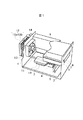
以下本発明の実施例を説明する。ここに示す例は電子機器であるデスクトップ型パーソナルコンピュータ(以下デスクトップPCという)に搭載したCPUの冷却に適用した例である。図1は本発明の第1の実施例を示すデスクトップPCの斜視図である。本実施例では熱輸送手段にヒートパイプを用いている。
【0026】
まず全体構成について説明する。筐体1の内部の底面付近にはマザーボード2があり、その上にはCPU3、チップセット4、メモリ5が搭載されている。この中でCPU3が高発熱部品である。また外部記憶装置として、HDD6、FDD7、CD-ROM8が搭載されている。CPU3には受熱部材としての受熱ヘッダ10が取付けられ、受熱ヘッダ10には熱輸送手段としてのヒートパイプ11の一端が取付けられている。ヒートパイプ11の構造を簡単に説明すると、銅製の中空管の内部に、極めて低い気圧で純水を封入し、この純水を熱を伝える作動流体としたものである。
【0027】
次に受熱ヘッダ10について説明する。受熱ヘッダ10は銅あるいはアルミといった伝熱性に優れた金属で出来ている。CPU3との接触面はサーマルコンパウンド、もしくは高熱伝導性シリコンゴムなどを挟んで圧着しており、CPU3で発生する熱が受熱ヘッダ10に効率よく伝わる構造になっている。また受熱ヘッダ10の内部にはヒートパイプ11の一端が埋め込まれており、受熱ヘッダ10の熱はヒートパイプ11に伝わる構造になっている。つまりCPU3の熱はヒートパイプ11に効率良く伝わる構造となっている。
【0028】
筐体1の背面にはファン13が取付けられている。ファン13は軸流ファンであり筐体1の内部側が吸気側となっている。筐体背面の外部にはファン13に対向して放熱部であるヒートシンク12が取付けられている。ヒートシンク12の材質は銅あるいはアルミといった伝熱性に優れた金属で出来ており、ベース12aとフィン12bから成る。なおフィン12bの形状はピンがマトリクス状に並んだものであるが、千鳥状に並んだもの、あるいは平板体を並べた形状でも良い。またフィン12bは筐体背面側を向く様に配置されている。つまり、フィン12bにファン13の風が当たる様になっている。ベース12aには、ヒートパイプ11の一端が埋め込まれており、ヒートパイプ11に伝わったCPU3の熱が効率良く伝わる構造になっている。
【0029】
ヒートパイプ11は、図2に示す様に受熱ヘッダ10からヒートシンク12の間は上方に傾斜をもたせており、ベース12a近傍で適宜に上方に折り曲げられ、ベース12aと繋がっている。つまり熱源であるCPU3は、放熱部であるヒートシンク12に対して低い位置、即ちボトムヒートの状態である為、ヒートパイプ11内部の作動流体は効率良く熱を運ぶことが出来る。作動液の動きについては後で詳しく説明する。ファン13の隣には電源9があり、この電源9にはACケーブル14が外部から接続されている。
【0030】
本実施例では、ヒートシンク12を筐体外部に取付けたが、筐体の中に一部が存在し他の部分が背面より突出するように取付けても良い。
【0031】
次に本実施例の冷却構造について説明する。まずCPU3が発熱する事により、CPU3に取付けられた受熱ヘッダ10に熱が伝わる。この時、ヒートパイプ11の外周部が受熱ヘッダ10により覆われている為、ヒートパイプ11にCPU3の熱が効率良く伝達される。従って受熱ヘッダ10に接したヒートパイプ11の内部では、伝わった熱により内部の作動流体が蒸発する。即ちこの部分がヒートパイプ11の蒸発部となる。
【0032】
蒸気となった作動流体は、温度が低く内部圧力が低いヒートシンク12に配置されたヒートパイプ11の端部に向かって流動し、ヒートシンク12に熱を奪われて凝縮する。従ってヒートパイプ11のヒートシンク12側の端部が凝縮部となる。前述の通り、ヒートパイプ11は勾配を持たせた状態に配置されているので、その動作状態はボトムヒート状態となり、作動流体の蒸発、凝縮のサイクルがスムーズに行われ、その結果、熱輸送能力が高くなる。なお凝縮して液相に戻った作動流体はヒートパイプ11内部を伝わって蒸発部まで帰還し、そこで再度過熱、蒸発する。ヒートパイプ11からヒートシンク12のベース12aに伝達されたCPU3の熱は、ベース12aのほぼ全域及びフィン12bに伝達される。
【0033】
次にファン13を動作させると、筐体1内の空気が図3の矢印21の方向に流れる。そしてこの空気はヒートシンク12のフィン12bを通過してベース12aと衝突し、矢印22、23、24、25の方向に排出される。この空気流によりヒートシンク12のベース12aとフィン12bに伝達された熱は放出される。なお本実施例ではヒートパイプを1本としているが、複数本使用しても良い。また、ヒートシンク12に外部から直接手が触れない様に、カバーを設けても良い。このカバーは筐体1と一体成形となっていても良い。
【0034】
以上の第1の実施例によれば、CPU3を冷却するヒートシンク12は筐体1の外部に取付けられるため、発熱量の多いCPU3を使用する場合、あるいは当初予想しなかった発熱量のCPU3に対しては、筐体外部のヒートシンク12を大きくすれば良く、筐体1のサイズを変更する必要がない。また、CPU3を冷却するヒートシンク12の配置を考慮する必要がないので、筐体1(電子機器)のサイズを小型化できる。さらにヒートシンク12の配置を、外部からのケーブル、例えばACケーブル14等が接続される筐体背面としてあるために、ヒートシンク12の設置に必要な面積の拡大を抑えることができる。
【0035】
図7を用いて具体的に説明すると、図7は電子機器が設置されたときの上面図であるが、電子機器の筐体1と壁41との距離は、筐体背面のACケーブル14の湾曲部分42の分だけ必要となるが、この距離42よりもヒートシンク12の奥行き43が小さければ実質的な設置面積は増大しない。多少ヒートシンク12の奥行き43が大きくても、実質的な設置面積の増加は少ない。また、ヒートシンク12からの排気方向は壁41と平行であるため、ヒートシンク12が壁41と接しても排気が塞がれることはない。
【0036】
ヒートシンク12の冷却効率であるが、図3に示す様にヒートシンク12に当たる風の流れ、即ちファン13の風21は、ヒートシンク12の最も熱い部分であるベース12aに対して衝突しながら排出される。即ち衝突噴流となる為冷却効率が良い。
【0037】
次に本実施例の静音化の効果について説明する。ファン13を停止させた場合、図3に示す様にファン13による矢印21、22、23、24、25の風の流れは停止するが、ヒートシンク12の温度は周囲温度よりも高い為、自然対流による矢印22の方向のゆっくりとした風の流れが生じる。矢印22の熱は筐体外部に放出される為、この熱により筐体内部の温度が上昇する事はない。このように、ファン13を停止した場合でも、ある程度の冷却効果が得られる。従ってCPU3が低負荷状態で発熱量が少ない場合にはファン13を停止してもCPU3を冷やす事が出来る。ファン13を停止させた場合、主たる騒音源は電源9のケースに内蔵されている電源ファンであるので、騒音の低減が可能となる。
【0038】
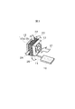
次に本発明の第2の実施例として、熱輸送手段に冷却液をポンプにより強制的に循環させる液冷システムを用いたものについて図4を用いて説明する。なお液冷システム以外の構成については前記第1の実施例と同じ構成なので説明および図示を省略する。
【0039】
CPU3に取付けられた受熱ヘッダ31は、CPU3との接触面は第1の実施例と同じであるが、内部には冷却液が流れており、熱が冷却液に伝わる構造になっている。図5は受熱ヘッダ31の内部構造を示す図であるが、伝熱性に優れた銅やアルミ等の金属板に蛇行状の溝を掘り、カバーにより密閉する構造である。これにより、蛇行状の流路が形成され、冷却液が入口から流入し、蛇行状の流路を通り、出口から流出する。
【0040】
ポンプ32は冷却液を受熱ヘッダ31とヒートシンク35の間を循環駆動させるものである。なお本実施例ではポンプ32の位置を受熱ヘッダ31の上部としたが、他の場所に配置しても良い。チューブ33及び金属管34は受熱ヘッダ31とヒートシンク35を繋ぎ、内部に冷却液を流すことで受熱ヘッダ31とヒートシンク35の熱輸送路となっている。
【0041】
全体の配管についてであるが、金属管を主体としており、部分的にゴム性のチューブ33を用いている。このチューブ33は曲げる事が出来る為、CPU3の交換等のメンテナンスが容易になる。つまりファン13やヒートシンク35を外す事無く、受熱ヘッダ31をCPU3から外す事が可能である。またチューブ33以外の配管を金属管とする事で水分透過を抑制している。
【0042】
ヒートシンク35はベース35a及びフィン35bから成っている。ベース35aの内部には冷却液が流れており、冷却液の熱がベース35a全体に伝わる構造になっている。図6はベース35aの内部構造を示す図であるが、基本的には前記受熱ヘッダ31と同じ作りであり、伝熱性に優れた銅やアルミ等の金属板に蛇行状の溝を掘り、カバーにより密閉する構造である。これにより、蛇行状の流路が形成され、冷却液が入口から流入し、蛇行状の流路を通り、出口から流出する。図4に戻るが、ベース35aの背面には、前記第1の実施例と同様、伝熱性に優れた銅やアルミ等の金属のピンがマトリクス状に並べられている。またヒートシンク35の筐体1への配置についても前記第1の実施例と同様である。
【0043】
金属管34に連通してリザーブタンク36が設けられている。リザーブタンク36は、基本的には冷却液を溜めておくものであるが、この目的以外にも次の2つの機能がある。1つは水分の蒸発による冷却液減少等で空気が混入した際には、タンク内に空気を溜めておく機能と、2つめは外部から液冷システム内部に冷却液を注入、排出する際のアクセス口の機能である。なお本実施例ではリザーブタンク36の位置をファン13の上部としたが、他の場所に配置しても良い。
【0044】
冷却液の流れる順路であるが、ポンプ32、受熱ヘッダ31の入口、受熱ヘッダ31の出口、ヒートシンク35のベース35aの入口、ベース35aの出口、リザーブタンク36、再びポンプ32という順路である。この様にポンプ32の冷却液を流す方向はヒートシンク35を通過後の冷却液を吸い込み、受熱ヘッダ31に排出する様にしている。これによりポンプ32には冷却後の冷却液が流れ、ポンプ32の加熱を防いでいる。
【0045】
次にヒートシンク35の他の構成例について図8、図9及び図10により説明する。図8の例は、伝熱性に優れた銅やアルミ等の金属の薄板に、伝熱性に優れた銅やアルミ等の金属からなる囲いを設け、この囲いの中に冷却液を流す蛇行状のパイプを配置し、囲いをカバーで密閉してベースを構成し、このベースの背面に伝熱性に優れた銅やアルミ等の金属からなるピンをマトリクス状に配列させた金属板を固定したものである。
【0046】
図9の例は、伝熱性に優れた銅やアルミ等の金属からなる収納箱に蛇行状のパイプを配置し、収納箱をカバーで密閉してベースを構成し、このベースの背面に伝熱性に優れた銅やアルミ等の金属からなる薄板(フィン)を平行に複数配置したものである。
【0047】
図10の例は、前記第2の実施例のベース35aを中空にし、伝熱性に優れた銅やアルミ等の金属からなる薄板(フィン)を複数水平に、フィン同士に隙間ができるように配置し、カバーで密閉したものである。ベースに流入した冷却液は、上部からフィンの表面を伝って、フィンの間を通って下部に流れ落ちる。
【0048】
これらの構造によれば、水分透過などにより循環経路中に空気が混入した場合でも、吐出口あるいは入口より出た空気はヒートシンクベース内部の上部に溜まることになる。即ち本構造のヒートシンクベースはタンクと同様に循環経路中の空気を溜めておくという機能を備えている。従って、冷却液を注入、排出する際のアクセス口をヒートシンクベースや他の場所に設ければタンクを不要とすることができる。
【0049】
この第2の実施例も前記第1の実施例と同じ効果を有するが、第2の実施例の場合は受熱ヘッダ及びヒートシンクのベースの内部には蛇行状の流路が設けられているために、第1の実施例よりも冷却効果は大きい。
【0050】
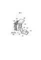
次に更なる静音効果を発揮する本発明の第3の実施例を図11、図12、図13及び図14を参照して説明する。第3の実施例はファン13と電源9の配置、接続構成以外は前記第1及び第2の実施例と同じ構成であるので、同じ構成についての図示及び説明は省略する。
【0051】
図11の構成は、電源9のケースの吸気口が形成されていない側面に開口部を形成し、この開口部とファン13の吸気側とをダクト51で接続し、吸気を電源9を介して行う構成である。筐体内の空気は矢印52方向に吸い寄せられ電源9のケースの吸気口からケース内に流入し、電源9を通ってダクト51に排出される。ファン13に吸い寄せられる排気流で電源9を冷却する事が出来るので電源ファンを省略することができる。したがって更なる静音化が図れる。
【0052】
図12の構成は、ファン13の吸気側に電源9を取付けたものである。電源9はケースに収容されており、ケースのファン13への取付面には開口あるいは排気口が形成されており、その反対側には吸気口が形成されている。ファン13の回転により矢印52の方向に筐体内の空気は流れ、電源9を通ってヒートシンク12あるいは35に排気される。この構成によっても排気流で電源9の冷却が出来るので電源ファンを省略することが出来る。したがって、前記第1及び第2の実施例よりもさらに静音化が可能となる。
【0053】
図13の構成は図12に示されるファン13と電源9の配置を逆にしたものである。図14の構成は、図13の構成例において、ファン13を電源9のケースの側面に設けたものである。
【0054】
以上の第3の実施例の静音化の効果は具体的には、空冷方式に較べて、騒音を約24dB低減することができる。
【0055】
【発明の効果】
本発明によれば筐体サイズを大型化することなく、また設置面積の増大を抑えてより高発熱部品の冷却が可能になる。
【図面の簡単な説明】
【図1】本発明の第1の実施例を示す斜視図である。
【図2】本発明の第1の実施例の冷却部の側面図である。
【図3】本発明の第1、第2及び第3の実施例の冷却部の斜視図である。
【図4】本発明の第2の実施例の冷却部の斜視図である。
【図5】本発明の第2の実施例の受熱ヘッダの構成図である。
【図6】本発明の第2の実施例のヒートシンクのベースの構成図である。
【図7】本発明の第1、第2及び第3の実施例の冷却部の上面図である。
【図8】本発明の第2の実施例のヒートシンクの他の構成例の構成図である。
【図9】本発明の第2の実施例のヒートシンクの他の構成例の構成図である。
【図10】本発明の第2の実施例のヒートシンクの他の構成例の構成図である。
【図11】本発明の第3の実施例の冷却部の斜視図である。
【図12】本発明の第3の実施例の冷却部の他の構成例の斜視図である。
【図13】本発明の第3の実施例の冷却部の他の構成例の斜視図である。
【図14】本発明の第3の実施例の冷却部の他の構成例の斜視図である。
【符号の説明】
1 電子機器の筐体
3 CPU
9 電源
10 ヒートパイプ用受熱ヘッダ
11 ヒートパイプ
12 ヒートパイプ用ヒートシンク
12a ヒートシンクベース
12b フィン
13 ファン
14 ACケーブル
21 ファンの吸気
22〜25 排気
31 液冷システム用受熱ヘッダ
32 ポンプ
33 ゴムチューブ
34 金属管
35 液冷システム用ヒートシンク
36 タンク
41 設置背面の壁
51 ダクト[0001]
BACKGROUND OF THE INVENTION
The present invention relates to an electronic apparatus having a cooling mechanism for a heat generating electronic component such as a CPU, and more particularly to a cooling structure using heat transporting and radiating means such as a heat pipe or a liquid cooling system.
[0002]
[Prior art]
In recent years, devices and integrated circuits used in personal computers, servers, and the like, particularly CPUs, have been increased in speed, but the amount of heat generation has increased accordingly. Currently, the direct cooling method for cooling a CPU is a direct air cooling method in which a heat sink is fixed to the CPU, a fan is attached to the CPU, and the cooling air is blown onto the heat sink. However, as the size and density of the device are reduced, the space around the CPU is limited, and the size of the heat sink is limited, which naturally limits the cooling capacity.
[0003]
On the other hand, in the cooling method using heat transport means such as a heat pipe and a liquid cooling system, the heat radiation part can be provided at a free position, and its size is less restricted, so the cooling limit is higher than that of the air cooling method. be able to. Therefore, in recent years, attempts have been made to apply these heat transporting means to the cooling of CPUs of electronic devices.
[0004]
As a conventional cooling method using these heat transporting means,
[0005]
On the other hand,
[0006]
[Patent Document 1]
"Japanese Patent Laid-Open No. 10-50910 (page 3-4, Fig. 1)"
[Patent Document 2]
"Japanese Patent Laid-Open No. 10-213370 (
[0007]
[Problems to be solved by the invention]
As described above, the cooling method using the heat transport means has a higher cooling limit than the direct air cooling method. However, when the heat dissipating part is arranged inside the case as in the above-mentioned
[0008]
In the technique of
[0009]
An object of the present invention is to solve these problems, and to provide a more efficient cooling structure, so that a highly heat-generating component can be mounted on a small housing and further to achieve a low noise.
[0010]
[Means for Solving the Problems]
In order to achieve the above object, in the electronic device of the present invention, the heat receiving member attached to the heat generating component installed in the housing and the air in the housing attached to a part of the wall surface of the housing. A fan for exhausting the outside of the housing, a base and fins arranged on the base, and facing the fan and projecting from the outside of the wall surface of the housing or from the wall surface, the fin being attached toward the housing side Heat sink, and a heat transport means connected to the heat sink and the heat receiving member.
[0011]
In order to achieve the above object, in an electronic device of the present invention, a heat generating component installed in a housing, a liquid flow path inside the heat generating component, and a liquid inlet and outlet are provided. A heat receiving member, a fan attached to a part of the wall surface of the housing for exhausting air in the housing to the outside of the housing, a base having a liquid flow path therein and a liquid inlet and outlet And a fin arranged on the base, facing the fan and projecting to the outside of the wall surface of the housing or to the outside from the wall surface and mounting the fin toward the housing side, and a heat sink A pipe connecting the inlet and outlet of the liquid flow path to the outlet and inlet of the liquid flow path of the heat receiving member; and a pump provided in the middle of the pipe.
[0012]
In order to achieve the above object, in the electronic device of the present invention, the heat generating component installed in the housing, the heat receiving member attached to the heat generating component, and the wall surface of the housing at a position higher than the heat receiving member. A fan for exhausting the air inside the casing attached to a part of the casing to the outside of the casing, a base and fins arranged on the base, and facing the fan outside the wall surface of the casing Alternatively, it includes a heat sink that protrudes outward from the wall surface and is attached with the fins facing the housing, and a heat pipe connected to the heat sink and the heat receiving member.
[0013]
To achieve the above object, in the electronic device of the present invention, a heat generating component installed in the housing, a heat receiving member attached to the heat generating component, a power source housed in a case having an air inlet, A fan attached to a part of the wall surface of the housing for exhausting the air in the housing to the outside of the housing, a duct connecting an intake side of the fan and an opening formed in the case of the power source, A heat sink having a base and fins arranged on the base, facing the fan and projecting to the outside of the wall surface of the housing or protruding from the wall surface toward the housing; and a heat sink And a heat transport means connected to the heat receiving member.
[0014]
In order to achieve the above object, in an electronic device according to the present invention, a heat generating component installed in a casing, a liquid flow path inside the heat generating component, and an inlet and an outlet for the liquid are provided. A heat receiving member, a power source housed in a case having an air inlet, a fan attached to a part of the wall surface of the housing for exhausting the air in the housing to the outside of the housing, and an intake side of the fan And a duct connecting the opening formed in the case of the power source, a base having a liquid flow path therein and having an inlet and an outlet for the liquid, and fins arranged on the base A heat sink that faces the fan outside the wall surface of the housing or protrudes from the wall surface to the outside and is mounted with the fins facing the housing side, an inlet and an outlet of a liquid flow path of the heat sink, and a liquid of the heat receiving member Channel outlet and inlet A connecting pipe, comprising a pump provided in the middle of the pipe.
[0015]
To achieve the above object, in the electronic device of the present invention, a heat generating component installed in the housing, a heat receiving member attached to the heat generating component, a power source housed in a case having an air inlet, A fan attached to a part of the wall surface of the casing at a position higher than the heat receiving member for exhausting air inside the casing to the outside of the casing, and an opening formed in the intake side of the fan and the case of the power source A duct connecting the first and second bases, a base and fins arranged on the base, facing the fan and projecting to the outside of the wall surface of the housing or from the wall surface to the outside so that the fin faces the housing side And a heat pipe connected to the heat receiving member.
[0016]
In order to achieve the above object, in the electronic device of the present invention, the heat generating component installed in the housing, the heat receiving member attached to the heat generating component, and a part of the wall surface of the housing are attached. A fan for exhausting the air in the casing to the outside of the casing, a power source attached to the intake side of the fan, a base, and fins arranged on the base, facing the fan, A heat sink that protrudes to the outside of the wall surface or protrudes from the wall surface with the fins facing the housing; and a heat transport means connected to the heat sink and the heat receiving member.
[0017]
In order to achieve the above object, in an electronic device according to the present invention, a heat generating component installed in a casing, a liquid flow path inside the heat generating component, and an inlet and an outlet for the liquid are provided. A heat receiving member, a fan attached to a part of the wall surface of the housing for exhausting the air in the housing to the outside of the housing, a power source attached to the intake side of the fan, and a liquid flow inside. A fin having a path and an inlet and an outlet for the liquid; and a fin arranged on the base. The fin is opposed to the fan and protrudes to the outside of the wall surface of the housing or from the wall surface to the outside. A heat sink attached to the housing side, a pipe connecting the inlet and outlet of the liquid channel of the heat sink and the outlet and inlet of the liquid channel of the heat receiving member, and a pump provided in the middle of the pipe It comprises.
[0018]
In order to achieve the above object, in the electronic device of the present invention, the heat generating component installed in the housing, the heat receiving member attached to the heat generating component, and the wall surface of the housing at a position higher than the heat receiving member. A fan for exhausting the air in the casing attached to a part of the casing to the outside of the casing, a power source mounted on the intake side of the fan, a base, and fins arranged on the base. A heat sink which faces the outside of the wall surface of the housing and protrudes outward from the wall surface and is attached with the fins facing the housing side, and a heat pipe connected to the heat sink and the heat receiving member are provided.
[0019]
In order to achieve the above object, in an electronic device according to the present invention, a heat generating component installed in a casing, a heat receiving member attached to the heat generating component, and a wall surface having an opening of the casing are housed in a case. A power source having a surface having an opening of the case attached thereto, and air inside the case attached to a surface other than the surface attached to the wall surface of the case of the power source case to the outside of the case through the power source. A fan for exhausting, a base, and fins arranged on the base have a fin facing the power source and projecting to the outside of the wall surface of the housing or from the wall surface to the housing side. An attached heat sink; and a heat transport means connected to the heat sink and the heat receiving member.
[0020]
In order to achieve the above object, in an electronic device according to the present invention, a heat generating component installed in a casing, a liquid flow path inside the heat generating component, and an inlet and an outlet for the liquid are provided. A heat receiving member having a power source, a power source that is housed in a case on a wall surface having an opening of the housing, and a surface having the opening of the case attached thereto, and a surface other than a surface that is attached to the wall surface of the housing of the case of the power source A fan for exhausting the air in the casing attached to the outside of the casing via the power source, a base having a liquid flow path therein and having an inlet and an outlet for the liquid, and the base. A heat sink attached to the outside of the wall surface of the housing or facing the power source so as to face the power source and projecting the fin toward the housing side, and an inlet of a liquid flow path of the heat sink; Outlet and heat receiving part To the pipe connecting the outlet and inlet of the liquid flow path, and a pump provided in the middle of the pipe provided.
[0021]
In order to achieve the above object, in the electronic apparatus of the present invention, the heat generating component installed in the housing, the heat receiving member attached to the heat generating component, and the opening of the housing at a position higher than the heat receiving member. A power source in which a surface having an opening of the case is attached to a wall surface having the case, and air in the case attached to a surface other than the surface attached to the wall surface of the case of the power source case. A fan for exhausting outside the casing through a power source, a base and fins arranged on the base, and facing the power source and projecting outside the wall surface of the casing or outside from the wall surface A heat sink attached with the fins facing the housing; and a heat pipe connected to the heat sink and the heat receiving member.
[0022]
A tank is provided in the middle of the piping.
[0023]
The base and fin of the heat sink are made of a metal having high heat conductivity, and the fin is an array of a plurality of pins.
[0024]
The heat sink is attached to a back surface to which a cable from the outside of the housing is connected.
[0025]
DETAILED DESCRIPTION OF THE INVENTION
Examples of the present invention will be described below. The example shown here is an example applied to cooling of a CPU mounted on a desktop personal computer (hereinafter referred to as a desktop PC) which is an electronic device. FIG. 1 is a perspective view of a desktop PC showing a first embodiment of the present invention. In this embodiment, a heat pipe is used as the heat transport means.
[0026]
First, the overall configuration will be described. A
[0027]
Next, the
[0028]
A
[0029]
As shown in FIG. 2, the
[0030]
In this embodiment, the
[0031]
Next, the cooling structure of the present embodiment will be described. First, when the
[0032]
The working fluid that has become a vapor flows toward the end of the
[0033]
Next, when the
[0034]
According to the first embodiment described above, since the
[0035]
More specifically, FIG. 7 is a top view when the electronic device is installed. The distance between the
[0036]
The cooling efficiency of the
[0037]
Next, the noise reduction effect of this embodiment will be described. When the
[0038]
Next, as a second embodiment of the present invention, a description will be given with reference to FIG. 4 using a liquid cooling system that forcibly circulates a cooling liquid to a heat transport means by a pump. Since the configuration other than the liquid cooling system is the same as that of the first embodiment, description and illustration are omitted.
[0039]
The
[0040]
The
[0041]
As for the entire piping, a metal tube is mainly used, and a
[0042]
The
[0043]
A
[0044]
The flow of the coolant flows through the
[0045]
Next, another configuration example of the
[0046]
In the example of FIG. 9, a serpentine pipe is arranged in a storage box made of metal such as copper or aluminum having excellent heat conductivity, and the storage box is sealed with a cover to form a base. A plurality of thin plates (fins) made of a metal such as copper or aluminum, which are superior to each other, are arranged in parallel.
[0047]
In the example of FIG. 10, the base 35a of the second embodiment is made hollow, and a plurality of thin plates (fins) made of metal such as copper or aluminum having excellent heat conductivity are arranged horizontally so that gaps are formed between the fins. And sealed with a cover. The coolant that has flowed into the base flows along the surface of the fin from the upper part, and flows down to the lower part through the space between the fins.
[0048]
According to these structures, even when air is mixed into the circulation path due to moisture permeation or the like, the air discharged from the discharge port or the inlet is collected in the upper part inside the heat sink base. That is, the heat sink base of this structure has a function of storing the air in the circulation path, like the tank. Accordingly, if an access port for injecting and discharging the cooling liquid is provided in the heat sink base and other places, the tank can be dispensed with.
[0049]
This second embodiment also has the same effect as the first embodiment, but in the case of the second embodiment, a meandering flow path is provided inside the base of the heat receiving header and the heat sink. The cooling effect is greater than in the first embodiment.
[0050]
Next, a third embodiment of the present invention that exhibits a further silent effect will be described with reference to FIGS. 11, 12, 13, and 14. FIG. Since the third embodiment has the same configuration as the first and second embodiments except for the arrangement and connection configuration of the
[0051]
In the configuration of FIG. 11, an opening is formed on the side surface of the case of the
[0052]
In the configuration of FIG. 12, a
[0053]
The configuration of FIG. 13 is obtained by reversing the arrangement of the
[0054]
Specifically, the noise reduction effect of the third embodiment described above can reduce noise by about 24 dB compared to the air cooling system.
[0055]
【The invention's effect】
According to the present invention, it is possible to cool higher heat-generating components without increasing the size of the casing and suppressing an increase in installation area.
[Brief description of the drawings]
FIG. 1 is a perspective view showing a first embodiment of the present invention.
FIG. 2 is a side view of a cooling unit according to the first embodiment of the present invention.
FIG. 3 is a perspective view of a cooling unit according to first, second and third embodiments of the present invention.
FIG. 4 is a perspective view of a cooling unit according to a second embodiment of the present invention.
FIG. 5 is a configuration diagram of a heat receiving header according to a second embodiment of the present invention.
FIG. 6 is a configuration diagram of a base of a heat sink according to a second embodiment of the present invention.
FIG. 7 is a top view of a cooling unit of the first, second and third embodiments of the present invention.
FIG. 8 is a configuration diagram of another configuration example of the heat sink according to the second embodiment of the present invention.
FIG. 9 is a configuration diagram of another configuration example of the heat sink according to the second embodiment of the present invention.
FIG. 10 is a configuration diagram of another configuration example of the heat sink according to the second embodiment of the present invention.
FIG. 11 is a perspective view of a cooling unit according to a third embodiment of the present invention.
FIG. 12 is a perspective view of another configuration example of the cooling unit according to the third embodiment of the present invention.
FIG. 13 is a perspective view of another configuration example of the cooling unit according to the third embodiment of the present invention.
FIG. 14 is a perspective view of another configuration example of the cooling unit according to the third embodiment of the present invention.
[Explanation of symbols]
1 Electronic equipment housing
3 CPU
9 Power supply
10 Heat receiving header for heat pipe
11 Heat pipe
12 Heat sink for heat pipe
12a heat sink base
12b Fin
13 fans
14 AC cable
21 Fan intake
22-25 exhaust
31 Heat receiving header for liquid cooling system
32 pumps
33 Rubber tube
34 Metal tube
35 Heat sink for liquid cooling system
36 tanks
41 Wall on the back of the installation
51 Duct
Claims (12)
該筐体の中に設置された発熱部品と、
該発熱部品に取付けられ、当該発熱部品の発生熱を熱伝達媒体に伝える受熱部材と、
前記筐体の壁面の一部に取付けられた当該筐体内の空気を筐体外へ排気するためのファンと、
前記熱伝達媒体を介して前記発熱部品の発生熱が前記受熱部材から熱輸送され、前記筐体背面の外側に前記ファンの排気流路に設けられて、前記ファンの排気の通気路と前記筐体の上方向の対流のための通気路を有し、前記ファンの停止時に前記発熱部品の発生熱を吸熱した前記熱伝達媒体を自然対流放熱して冷却するとともに、前記ファンの動作時には前記ファンの排気により前記熱伝達媒体を冷却する放熱部と、
前記受熱部材と前記放熱部の間を接続して前記熱伝達媒体を移動する熱輸送手段と、を具備し、
前記放熱部は、ケーブルが接続される前記筐体背面に、前記ケーブルの湾曲部の大きさより小さい奥行きを有して設けられることを特徴とする冷却機構を備えた電子機器。An electronic device casing,
A heat generating component installed in the housing;
A heat receiving member attached to the heat generating component and transmitting heat generated by the heat generating component to a heat transfer medium;
A fan for exhausting the air in the casing attached to a part of the wall surface of the casing to the outside of the casing;
Heat generated by the heat generating component is transported from the heat receiving member through the heat transfer medium, and is provided in the exhaust passage of the fan outside the rear surface of the housing. A ventilation passage for upward convection of the body, which cools the heat transfer medium that has absorbed the heat generated by the heat-generating component when the fan is stopped, and radiates and cools the heat transfer medium; A heat dissipating part for cooling the heat transfer medium by exhausting
A heat transport means for moving the heat transfer medium by connecting between the heat receiving member and the heat radiating portion ;
An electronic apparatus provided with a cooling mechanism, wherein the heat radiating portion is provided on the rear surface of the housing to which a cable is connected and has a depth smaller than the curved portion of the cable .
前記熱伝達媒体は冷却液であり、
前記熱輸送手段は、前記受熱部材と前記放熱部を前記冷却液が還流するように接続し、
前記熱輸送手段の途中に前記冷却液を循環させるポンプを有することを特徴とする冷却機構を備えた電子機器。In the electronic device provided with the cooling mechanism according to claim 1,
The heat transfer medium is a coolant;
The heat transport means connects the heat receiving member and the heat radiating part so that the cooling liquid flows back,
An electronic apparatus provided with a cooling mechanism, comprising a pump for circulating the coolant in the middle of the heat transporting means.
前記熱輸送手段は、前記受熱部材と前記放熱部を接続するヒートパイプであり、
前記放熱部と前記ファンは、前記受熱部材より高い位置に設けられることを特徴とする冷却機構を備えた電子機器。In the electronic device provided with the cooling mechanism according to claim 1,
The heat transport means is a heat pipe connecting the heat receiving member and the heat radiating portion,
The electronic device having a cooling mechanism, wherein the heat dissipating part and the fan are provided at a position higher than the heat receiving member.
該筐体の中に設置された発熱部品と、
該発熱部品に取付けられ、当該発熱部品の発生熱を熱伝達媒体に伝える受熱部材と、
吸気口を有するケースに収められた電源と、
前記筐体の壁面の一部に取付けられた当該筐体内の空気を筐体外へ排気するためのファンと、
該ファンの吸気側と前記電源のケースに形成された開口部とを接続するダクトと、
ベースと該ベースに配列されたフィンとを有し、前記ファンに対向して前記筐体の壁面の外側に若しくは当該壁面から外部に突出して前記フィンを筐体側に向けて取付けられ、前記熱伝達媒体を冷却するヒートシンクと、
該ヒートシンクと前記受熱部材に接続され、前記熱伝達媒体を移動する熱輸送手段とを具備することを特徴とする冷却機構を備えた電子機器。A housing,
A heat generating component installed in the housing;
A heat receiving member attached to the heat generating component and transmitting heat generated by the heat generating component to a heat transfer medium;
A power supply housed in a case with an air inlet;
A fan for exhausting the air in the casing attached to a part of the wall surface of the casing to the outside of the casing;
A duct connecting the intake side of the fan and an opening formed in the case of the power source;
A heat exchanger that includes a base and fins arranged on the base, and that is attached to the outside of the wall surface of the housing so as to face the fan or project outward from the wall surface toward the housing side. A heat sink that cools the medium;
An electronic apparatus provided with a cooling mechanism, comprising: a heat transporting means connected to the heat sink and the heat receiving member to move the heat transfer medium.
前記熱伝達媒体は冷却液であり、
前記熱輸送手段は、前記受熱部材と前記放熱部を前記冷却液が還流するように接続し、
前記熱輸送手段の途中に前記冷却液を循環させるポンプを有することを特徴とする冷却機構を備えた電子機器。In the electronic device provided with the cooling mechanism according to claim 4,
The heat transfer medium is a coolant;
The heat transport means connects the heat receiving member and the heat radiating part so that the cooling liquid flows back,
An electronic apparatus provided with a cooling mechanism, comprising a pump for circulating the coolant in the middle of the heat transporting means.
前記熱輸送手段は、前記受熱部材と前記ヒートシンクを接続するヒートパイプであり、
前記ヒートシンクと前記電源と前記ファンは、前記受熱部材より高い位置に設けられることを特徴とする冷却機構を備えた電子機器。In the electronic device provided with the cooling mechanism according to claim 4,
The heat transport means is a heat pipe connecting the heat receiving member and the heat sink,
The electronic apparatus having a cooling mechanism, wherein the heat sink, the power source, and the fan are provided at a position higher than the heat receiving member.
該筐体の中に設置された発熱部品と、
該発熱部品に取付けられ、当該発熱部品の発生熱を熱伝達媒体に伝える受熱部材と、
前記筐体の壁面の一部に取付けられた当該筐体内の空気を筐体外へ排気するためのファンと、
該ファンの吸気側に取付けられた電源と、
前記熱伝達媒体を介して前記発熱部品の発生熱が前記受熱部材から熱輸送され、前記筐体背面の外側に前記ファンの排気流路に設けられて、前記ファンの排気の通気路と前記筐体の上方向の対流のための通気路を有し、前記ファンの停止時に前記発熱部品の発生熱を吸熱した前記熱伝達媒体を自然対流放熱して冷却するとともに、前記ファンの動作時には前記ファンの排気により前記熱伝達媒体を冷却する放熱部と、
前記受熱部材と前記放熱部の間を接続して前記熱伝達媒体を移動する熱輸送手段と、を備え、
前記放熱部は、ケーブルが接続される前記筐体背面に、前記ケーブルの湾曲部の大きさより小さい奥行きを有して設けられることを特徴とする冷却機構を備えた電子機器。An electronic device casing,
A heat generating component installed in the housing;
A heat receiving member attached to the heat generating component and transmitting heat generated by the heat generating component to a heat transfer medium;
A fan for exhausting the air in the casing attached to a part of the wall surface of the casing to the outside of the casing;
A power supply attached to the intake side of the fan;
Heat generated by the heat generating component is transported from the heat receiving member through the heat transfer medium, and is provided in the exhaust passage of the fan outside the rear surface of the housing. A ventilation passage for upward convection of the body, which cools the heat transfer medium that has absorbed the heat generated by the heat-generating component when the fan is stopped, and radiates and cools the heat transfer medium; A heat dissipating part for cooling the heat transfer medium by exhausting
A heat transport means for moving the heat transfer medium by connecting between the heat receiving member and the heat radiating portion;
An electronic apparatus provided with a cooling mechanism, wherein the heat radiating portion is provided on the rear surface of the housing to which a cable is connected and has a depth smaller than the curved portion of the cable .
前記熱伝達媒体は冷却液であり、
前記熱輸送手段は、前記受熱部材と前記放熱部を前記冷却液が還流するように接続し、
前記熱輸送手段の途中に前記冷却液を循環させるポンプを有することを特徴とする冷却機構を備えた電子機器。In the electronic device provided with the cooling mechanism according to claim 7,
The heat transfer medium is a coolant;
The heat transport means connects the heat receiving member and the heat radiating part so that the cooling liquid flows back,
An electronic apparatus provided with a cooling mechanism, comprising a pump for circulating the coolant in the middle of the heat transporting means.
前記熱輸送手段は、前記受熱部材と前記放熱部を接続するヒートパイプであり、
前記放熱部と前記ファンは、前記受熱部材より高い位置に設けられることを特徴とする冷却機構を備えた電子機器。In the electronic device provided with the cooling mechanism according to claim 7,
The heat transport means is a heat pipe connecting the heat receiving member and the heat radiating portion,
The electronic device having a cooling mechanism, wherein the heat dissipating part and the fan are provided at a position higher than the heat receiving member.
該筐体の中に設置された発熱部品と、
該発熱部品に取付けられ、当該発熱部品の発生熱を熱伝達媒体に伝える受熱部材と、
前記筐体の開口を有する壁面に、ケースに収められ当該ケースの開口を有する面が取付けられた電源と、
該電源のケースの前記筐体の壁面に取付けられた面以外の面に取付けられた当該筐体内の空気を前記電源を介して筐体外へ排気するためのファンと、
ベースと該ベースに配列されたフィンとを有し、前記電源に対向して前記筐体の壁面の外側に若しくは当該壁面から外部に突出して前記フィンを筐体側に向けて取付けられ、前記熱伝達媒体を冷却するヒートシンクと、
該ヒートシンクと前記受熱部材に接続され、前記熱伝達媒体を移動する熱輸送手段と、
を具備することを特徴とする冷却機構を備えた電子機器。A housing,
A heat generating component installed in the housing;
A heat receiving member attached to the heat generating component and transmitting heat generated by the heat generating component to a heat transfer medium;
A power source in which a surface that is housed in a case and has an opening of the case is attached to a wall surface having an opening of the housing;
A fan for exhausting the air in the housing attached to a surface other than the surface attached to the wall surface of the housing of the power supply case to the outside of the housing via the power supply;
A heat sink that has a base and fins arranged on the base, and that is mounted on the outside of the wall surface of the housing facing the power source or projecting outward from the wall surface toward the housing side; A heat sink that cools the medium;
A heat transport means connected to the heat sink and the heat receiving member to move the heat transfer medium;
An electronic device comprising a cooling mechanism, comprising:
前記熱伝達媒体は冷却液であり、
前記熱輸送手段は、前記受熱部材と前記ヒートシンクを前記冷却液が還流するように接続し、
前記熱輸送手段の途中に前記冷却液を循環させるポンプを有することを特徴とする冷却機構を備えた電子機器。In the electronic device provided with the cooling mechanism according to claim 10,
The heat transfer medium is a coolant;
The heat transport means connects the heat receiving member and the heat sink so that the coolant flows back,
An electronic apparatus provided with a cooling mechanism, comprising a pump for circulating the coolant in the middle of the heat transporting means.
前記熱輸送手段は、前記受熱部材と前記ヒートシンクを接続するヒートパイプであり、
前記ヒートシンクと前記電源と前記ファンは、前記受熱部材より高い位置に設けられることを特徴とする冷却機構を備えた電子機器。In the electronic device provided with the cooling mechanism according to claim 10,
The heat transport means is a heat pipe connecting the heat receiving member and the heat sink,
The electronic apparatus having a cooling mechanism, wherein the heat sink, the power source, and the fan are provided at a position higher than the heat receiving member.
Priority Applications (3)
| Application Number | Priority Date | Filing Date | Title |
|---|---|---|---|
| JP2002279570A JP3757200B2 (en) | 2002-09-25 | 2002-09-25 | Electronic equipment with cooling mechanism |
| US10/414,152 US6778394B2 (en) | 2002-09-25 | 2003-04-16 | Electronic device having a heat dissipation member |
| CNB031226353A CN1310317C (en) | 2002-09-25 | 2003-04-18 | Electronic device having a heat dissipation member |
Applications Claiming Priority (1)
| Application Number | Priority Date | Filing Date | Title |
|---|---|---|---|
| JP2002279570A JP3757200B2 (en) | 2002-09-25 | 2002-09-25 | Electronic equipment with cooling mechanism |
Related Child Applications (2)
| Application Number | Title | Priority Date | Filing Date |
|---|---|---|---|
| JP2005108472A Division JP3727647B2 (en) | 2005-04-05 | 2005-04-05 | Electronic equipment cooling device |
| JP2005341930A Division JP4744280B2 (en) | 2005-11-28 | 2005-11-28 | Electronic equipment with cooling mechanism |
Publications (3)
| Publication Number | Publication Date |
|---|---|
| JP2004116864A JP2004116864A (en) | 2004-04-15 |
| JP2004116864A5 JP2004116864A5 (en) | 2005-09-15 |
| JP3757200B2 true JP3757200B2 (en) | 2006-03-22 |
Family
ID=32063503
Family Applications (1)
| Application Number | Title | Priority Date | Filing Date |
|---|---|---|---|
| JP2002279570A Expired - Fee Related JP3757200B2 (en) | 2002-09-25 | 2002-09-25 | Electronic equipment with cooling mechanism |
Country Status (3)
| Country | Link |
|---|---|
| US (1) | US6778394B2 (en) |
| JP (1) | JP3757200B2 (en) |
| CN (1) | CN1310317C (en) |
Families Citing this family (81)
| Publication number | Priority date | Publication date | Assignee | Title |
|---|---|---|---|---|
| US20050006365A1 (en) * | 2003-07-11 | 2005-01-13 | Lincoln Global, Inc. | Heat dissipation platform |
| US20050047085A1 (en) * | 2003-08-26 | 2005-03-03 | Nagui Mankaruse | High performance cooling systems |
| JP4140495B2 (en) * | 2003-09-25 | 2008-08-27 | 株式会社日立製作所 | Cooling module |
| TWM251442U (en) * | 2003-11-07 | 2004-11-21 | Hon Hai Prec Ind Co Ltd | Liquid cooling apparatus |
| JP2005175075A (en) * | 2003-12-09 | 2005-06-30 | Hitachi Cable Ltd | Liquid circulating type cooling device |
| JP4272503B2 (en) * | 2003-12-17 | 2009-06-03 | 株式会社日立製作所 | Liquid cooling system |
| US7273088B2 (en) * | 2003-12-17 | 2007-09-25 | Hewlett-Packard Development Company, L.P. | One or more heat exchanger components in major part operably locatable outside computer chassis |
| JP4408224B2 (en) * | 2004-01-29 | 2010-02-03 | 富士通株式会社 | Housing with heat dissipation function |
| JP2005229020A (en) * | 2004-02-16 | 2005-08-25 | Hitachi Ltd | Liquid-cooled system and electronic equipment having the same |
| US20050213293A1 (en) * | 2004-03-24 | 2005-09-29 | Yin-Hung Chen | Internal arrangement of computer case |
| US20050219820A1 (en) * | 2004-04-01 | 2005-10-06 | Belady Christian L | System and method for heat dissipation |
| US7359197B2 (en) * | 2004-04-12 | 2008-04-15 | Nvidia Corporation | System for efficiently cooling a processor |
| US7002799B2 (en) * | 2004-04-19 | 2006-02-21 | Hewlett-Packard Development Company, L.P. | External liquid loop heat exchanger for an electronic system |
| JP2005340745A (en) * | 2004-05-27 | 2005-12-08 | Ts Heatronics Co Ltd | Electric and electronic device power supply unit |
| JP4056504B2 (en) * | 2004-08-18 | 2008-03-05 | Necディスプレイソリューションズ株式会社 | COOLING DEVICE AND ELECTRONIC DEVICE HAVING THE SAME |
| DE102004042034A1 (en) * | 2004-08-26 | 2006-03-16 | Laing, Oliver | An electrical device power supply device and method for providing electrical power to components of an electrical device |
| DE102004043398A1 (en) * | 2004-09-03 | 2006-06-22 | Laing, Oliver | Cooling assembly e.g. for electrical appliance like PC, has several heat sources, and electrical appliance provided with electric power supply unit encompassing heat source |
| WO2006021359A1 (en) * | 2004-08-26 | 2006-03-02 | Laing, Oliver | Cooling assembly for an electrical appliance, and method for cooling liquid |
| KR100624092B1 (en) * | 2004-09-16 | 2006-09-18 | 잘만테크 주식회사 | Computer |
| FR2876812B1 (en) * | 2004-10-15 | 2006-12-22 | J C C Chereau Aeronautique | COOLING FLUID DEVICE FOR COMPUTER |
| CN100561717C (en) * | 2004-10-21 | 2009-11-18 | 鸿富锦精密工业(深圳)有限公司 | Heat radiator of electronic element and combination thereof |
| US7277282B2 (en) * | 2004-12-27 | 2007-10-02 | Intel Corporation | Integrated circuit cooling system including heat pipes and external heat sink |
| TW200633628A (en) * | 2005-03-10 | 2006-09-16 | Quanta Comp Inc | Second degree curve shape heat pipe and fins heat sink |
| DE102005016115B4 (en) * | 2005-04-08 | 2007-12-20 | Rittal Gmbh & Co. Kg | Arrangement for cooling an electronic device |
| CN100372108C (en) * | 2005-04-19 | 2008-02-27 | 台达电子工业股份有限公司 | Radiating moudle of electronic device |
| CN100584166C (en) * | 2005-05-07 | 2010-01-20 | 富准精密工业(深圳)有限公司 | Liquid cooling heat radiator |
| CN100499089C (en) * | 2005-06-08 | 2009-06-10 | 富准精密工业(深圳)有限公司 | Radiator |
| JP2007011975A (en) * | 2005-07-04 | 2007-01-18 | Ricoh Co Ltd | Cooling structure of electronic device case |
| JP2007035722A (en) * | 2005-07-22 | 2007-02-08 | Mitsubishi Electric Corp | Heat radiating structure of onboard device |
| US7686071B2 (en) * | 2005-07-30 | 2010-03-30 | Articchoke Enterprises Llc | Blade-thru condenser having reeds and heat dissipation system thereof |
| JP4700471B2 (en) * | 2005-10-25 | 2011-06-15 | 株式会社リコー | Information processing apparatus and manufacturing method thereof |
| US7447025B2 (en) * | 2005-11-01 | 2008-11-04 | Fu Zhun Precision Industry (Shen Zhen) Co., Ltd. | Heat dissipation device |
| US20070097646A1 (en) * | 2005-11-02 | 2007-05-03 | Xue-Wen Peng | Heat dissipating apparatus for computer add-on cards |
| JP2007164553A (en) * | 2005-12-15 | 2007-06-28 | Giga-Byte Technology Co Ltd | Power supply system, heat radiation device and heat radiation method |
| US7733659B2 (en) * | 2006-08-18 | 2010-06-08 | Delphi Technologies, Inc. | Lightweight audio system for automotive applications and method |
| FR2910779A1 (en) * | 2006-12-21 | 2008-06-27 | Thales Sa | Electronic equipment casing i.e. electronic rack, for aircraft, has heat collectors inserted between hot spots and inner thermal radiators, and heat conductors connecting outer thermal radiator with collectors through front wall of casing |
| CN101242732B (en) * | 2007-02-08 | 2011-01-05 | 鸿富锦精密工业(深圳)有限公司 | Heat radiator combination |
| TW200837538A (en) * | 2007-03-05 | 2008-09-16 | Dfi Inc | Heat dissipation module and desktop host using the same |
| US7474527B2 (en) * | 2007-03-05 | 2009-01-06 | Dfi, Inc. | Desktop personal computer and thermal module thereof |
| WO2008109805A2 (en) * | 2007-03-07 | 2008-09-12 | Asetek Usa Inc. | Hybrid liquid-air cooled graphics display adapter |
| JP4579269B2 (en) * | 2007-05-25 | 2010-11-10 | トヨタ自動車株式会社 | Cooling system |
| US8144458B2 (en) * | 2007-06-13 | 2012-03-27 | Hewlett-Packard Development Company, L.P. | Component layout in an enclosure |
| US20080310105A1 (en) * | 2007-06-14 | 2008-12-18 | Chia-Chun Cheng | Heat dissipating apparatus and water cooling system having the same |
| US20100124022A1 (en) * | 2008-11-14 | 2010-05-20 | Suad Causevic | Thermoelectric cooling apparatus and method for cooling an integrated circuit |
| JP4997215B2 (en) * | 2008-11-19 | 2012-08-08 | 株式会社日立製作所 | Server device |
| TW201036527A (en) * | 2009-03-19 | 2010-10-01 | Acbel Polytech Inc | Large-area liquid-cooled heat-dissipation device |
| CN101873785A (en) * | 2009-04-21 | 2010-10-27 | 鸿富锦精密工业(深圳)有限公司 | Electronic equipment cabinet |
| US8081463B2 (en) * | 2009-06-16 | 2011-12-20 | Asia Vital Components Co., Ltd. | Water-cooled communication chassis |
| US8000101B2 (en) * | 2009-07-23 | 2011-08-16 | Hewlett-Packard Development Company, L.P. | System and method for attaching liquid cooling apparatus to a chassis |
| JP4892078B2 (en) * | 2010-05-11 | 2012-03-07 | 株式会社東芝 | Electronics |
| US8144467B2 (en) | 2010-05-26 | 2012-03-27 | International Business Machines Corporation | Dehumidifying and re-humidifying apparatus and method for an electronics rack |
| US9038406B2 (en) | 2010-05-26 | 2015-05-26 | International Business Machines Corporation | Dehumidifying cooling apparatus and method for an electronics rack |
| US8189334B2 (en) | 2010-05-26 | 2012-05-29 | International Business Machines Corporation | Dehumidifying and re-humidifying cooling apparatus and method for an electronics rack |
| US7905096B1 (en) * | 2010-05-26 | 2011-03-15 | International Business Machines Corporation | Dehumidifying and re-humidifying air cooling for an electronics rack |
| CN102819303A (en) * | 2011-06-09 | 2012-12-12 | 鸿富锦精密工业(深圳)有限公司 | Computer case |
| CN103249275A (en) * | 2012-02-07 | 2013-08-14 | 鸿富锦精密工业(深圳)有限公司 | Heat dissipation system |
| US10123464B2 (en) | 2012-02-09 | 2018-11-06 | Hewlett Packard Enterprise Development Lp | Heat dissipating system |
| US9529395B2 (en) | 2012-03-12 | 2016-12-27 | Hewlett Packard Enterprise Development Lp | Liquid temperature control cooling |
| CN104685984A (en) | 2012-09-28 | 2015-06-03 | 惠普发展公司,有限责任合伙企业 | Cooling assembly |
| US9788452B2 (en) | 2012-10-31 | 2017-10-10 | Hewlett Packard Enterprise Development Lp | Modular rack system |
| CN107743351B (en) | 2013-01-31 | 2020-11-06 | 慧与发展有限责任合伙企业 | Apparatus for providing liquid cooling, cooling system and method for cooling |
| JP6394331B2 (en) * | 2013-12-27 | 2018-09-26 | 富士通株式会社 | Cooling parts and electronic equipment |
| US9326556B2 (en) * | 2014-07-10 | 2016-05-03 | Frank Leon | Personal cooling assembly |
| CN105992492A (en) * | 2015-02-09 | 2016-10-05 | 丁彥允 | Computer heat radiation module assembly of stack type printed circuit boards |
| US9575521B1 (en) * | 2015-07-30 | 2017-02-21 | Dell Products L.P. | Chassis external wall liquid cooling system |
| CN105163562B (en) * | 2015-08-26 | 2018-03-20 | 杭州电子科技大学 | A kind of adherent heat abstractor of distance type |
| US10031564B2 (en) * | 2015-12-28 | 2018-07-24 | Lenovo (Beijing) Limited | Heat dissipation apparatus and system for an electronic device |
| US10080067B2 (en) * | 2015-12-31 | 2018-09-18 | Infinera Corporation | Heat relay network system for telecommunication equipment |
| CN105792625A (en) * | 2016-05-25 | 2016-07-20 | 国网河北省电力公司衡水供电分公司 | Control engine heat radiation device for power scheduling system |
| JP2018036531A (en) * | 2016-08-31 | 2018-03-08 | 京セラドキュメントソリューションズ株式会社 | Image forming apparatus |
| CN106548705A (en) * | 2016-10-26 | 2017-03-29 | 方迪勇 | A kind of electronic information display screen |
| US20180170553A1 (en) * | 2016-12-20 | 2018-06-21 | Qualcomm Incorporated | Systems, methods, and apparatus for passive cooling of uavs |
| CN107765795A (en) | 2017-11-08 | 2018-03-06 | 北京图森未来科技有限公司 | A kind of computer server |
| CN107885295A (en) * | 2017-11-08 | 2018-04-06 | 北京图森未来科技有限公司 | A kind of cooling system |
| CN109764705A (en) * | 2019-03-04 | 2019-05-17 | 安徽理工大学 | To the portable unit of article heat dissipation when a kind of environment temperature is higher |
| JP6813197B2 (en) * | 2019-04-26 | 2021-01-13 | Necプラットフォームズ株式会社 | Heat dissipation structure |
| JP6787604B1 (en) * | 2019-06-03 | 2020-11-18 | Necプラットフォームズ株式会社 | Cooling system |
| CN110399022A (en) * | 2019-06-28 | 2019-11-01 | 联想(北京)有限公司 | Electronic equipment |
| CN112954949A (en) * | 2019-12-10 | 2021-06-11 | 台达电子工业股份有限公司 | Network equipment power supply and heat dissipation system for same |
| US11395443B2 (en) | 2020-05-11 | 2022-07-19 | Coolit Systems, Inc. | Liquid pumping units, and related systems and methods |
| CN113747705A (en) * | 2021-08-11 | 2021-12-03 | 襄阳奥东电气有限公司 | Integrated soft starting device and controller thereof |
Family Cites Families (10)
| Publication number | Priority date | Publication date | Assignee | Title |
|---|---|---|---|---|
| JP3739142B2 (en) | 1996-08-05 | 2006-01-25 | 株式会社フジクラ | Electronic element cooling structure |
| US6459576B1 (en) * | 1996-09-30 | 2002-10-01 | Intel Corporation | Fan based heat exchanger |
| TW422946B (en) | 1996-12-31 | 2001-02-21 | Compaq Computer Corp | Apparatus for liquid cooling of specific computer components |
| US20020053421A1 (en) * | 1997-09-10 | 2002-05-09 | Kabushiki Kaisha Toshiba | Heat dissipating structure for electronic apparatus |
| US6166907A (en) * | 1999-11-26 | 2000-12-26 | Chien; Chuan-Fu | CPU cooling system |
| CN2422727Y (en) * | 2000-05-12 | 2001-03-07 | 讯凯国际股份有限公司 | Radiator with heat-conducting pipe |
| US6407916B1 (en) * | 2000-06-12 | 2002-06-18 | Intel Corporation | Computer assembly for cooling high powered microprocessors |
| US6418018B1 (en) * | 2000-12-21 | 2002-07-09 | Foxconn Precision Components Co., Ltd. | Heat removal system |
| US6437982B1 (en) * | 2001-02-20 | 2002-08-20 | Intel Corporation | External attached heat sink fold out |
| US6560104B2 (en) * | 2001-03-27 | 2003-05-06 | Thermal Corp. | Portable computer and docking station cooling |
-
2002
- 2002-09-25 JP JP2002279570A patent/JP3757200B2/en not_active Expired - Fee Related
-
2003
- 2003-04-16 US US10/414,152 patent/US6778394B2/en not_active Expired - Lifetime
- 2003-04-18 CN CNB031226353A patent/CN1310317C/en not_active Expired - Fee Related
Also Published As
| Publication number | Publication date |
|---|---|
| CN1310317C (en) | 2007-04-11 |
| JP2004116864A (en) | 2004-04-15 |
| US6778394B2 (en) | 2004-08-17 |
| CN1485904A (en) | 2004-03-31 |
| US20040070949A1 (en) | 2004-04-15 |
Similar Documents
| Publication | Publication Date | Title |
|---|---|---|
| JP3757200B2 (en) | Electronic equipment with cooling mechanism | |
| JP3594900B2 (en) | Display integrated computer | |
| US7466553B2 (en) | Cooling system | |
| JP4551261B2 (en) | Cooling jacket | |
| US20090001560A1 (en) | Embedded Heat Pipe In A Hybrid Cooling System | |
| JP3979143B2 (en) | Cooling device for information processing equipment | |
| KR101005404B1 (en) | Heat absorption member, cooling device, and electronic apparatus | |
| US20050052848A1 (en) | Liquid cooling system | |
| US20070227699A1 (en) | Method, apparatus and system for flow distribution through a heat exchanger | |
| JP2006207881A (en) | Cooling device and electronic apparatus comprising the same | |
| TW200808164A (en) | Electronic apparatus | |
| JP4720688B2 (en) | Electronic control unit cooling system | |
| US10874034B1 (en) | Pump driven liquid cooling module with tower fins | |
| JP2012204554A (en) | Cooling unit | |
| US20070076376A1 (en) | Method, apparatus and computer system for providing for the transfer of thermal energy | |
| JP4744280B2 (en) | Electronic equipment with cooling mechanism | |
| JP3727647B2 (en) | Electronic equipment cooling device | |
| JP4682858B2 (en) | Cooling device for electronic equipment | |
| JP2005210088A (en) | Cooling device in closed cabinet | |
| JP2005317033A (en) | Display device integrated computer, and cooling module used therein | |
| JP2008211001A (en) | Electronic device cooling apparatus | |
| JP3827594B2 (en) | CPU cooling device | |
| JP2004094961A (en) | Display unit integrated computer system and cooling module used for it | |
| TW201223430A (en) | Heat sink, liquid cooling unit, and electronic apparatus | |
| JP4332359B2 (en) | Computer cooling system |
Legal Events
| Date | Code | Title | Description |
|---|---|---|---|
| A521 | Request for written amendment filed |
Free format text: JAPANESE INTERMEDIATE CODE: A523 Effective date: 20050405 |
|
| A621 | Written request for application examination |
Free format text: JAPANESE INTERMEDIATE CODE: A621 Effective date: 20050405 |
|
| A871 | Explanation of circumstances concerning accelerated examination |
Free format text: JAPANESE INTERMEDIATE CODE: A871 Effective date: 20050405 |
|
| A975 | Report on accelerated examination |
Free format text: JAPANESE INTERMEDIATE CODE: A971005 Effective date: 20050609 |
|
| A131 | Notification of reasons for refusal |
Free format text: JAPANESE INTERMEDIATE CODE: A131 Effective date: 20050621 |
|
| A521 | Request for written amendment filed |
Free format text: JAPANESE INTERMEDIATE CODE: A523 Effective date: 20050819 |
|
| RD02 | Notification of acceptance of power of attorney |
Free format text: JAPANESE INTERMEDIATE CODE: A7422 Effective date: 20050819 |
|
| A131 | Notification of reasons for refusal |
Free format text: JAPANESE INTERMEDIATE CODE: A131 Effective date: 20051004 |
|
| A521 | Request for written amendment filed |
Free format text: JAPANESE INTERMEDIATE CODE: A523 Effective date: 20051128 |
|
| TRDD | Decision of grant or rejection written | ||
| A01 | Written decision to grant a patent or to grant a registration (utility model) |
Free format text: JAPANESE INTERMEDIATE CODE: A01 Effective date: 20051220 |
|
| A61 | First payment of annual fees (during grant procedure) |
Free format text: JAPANESE INTERMEDIATE CODE: A61 Effective date: 20051226 |
|
| R150 | Certificate of patent or registration of utility model |
Free format text: JAPANESE INTERMEDIATE CODE: R150 Ref document number: 3757200 Country of ref document: JP Free format text: JAPANESE INTERMEDIATE CODE: R150 |
|
| FPAY | Renewal fee payment (event date is renewal date of database) |
Free format text: PAYMENT UNTIL: 20100106 Year of fee payment: 4 |
|
| FPAY | Renewal fee payment (event date is renewal date of database) |
Free format text: PAYMENT UNTIL: 20110106 Year of fee payment: 5 |
|
| FPAY | Renewal fee payment (event date is renewal date of database) |
Free format text: PAYMENT UNTIL: 20120106 Year of fee payment: 6 |
|
| FPAY | Renewal fee payment (event date is renewal date of database) |
Free format text: PAYMENT UNTIL: 20130106 Year of fee payment: 7 |
|
| S111 | Request for change of ownership or part of ownership |
Free format text: JAPANESE INTERMEDIATE CODE: R313115 |
|
| R350 | Written notification of registration of transfer |
Free format text: JAPANESE INTERMEDIATE CODE: R350 |
|
| S111 | Request for change of ownership or part of ownership |
Free format text: JAPANESE INTERMEDIATE CODE: R313115 |
|
| R350 | Written notification of registration of transfer |
Free format text: JAPANESE INTERMEDIATE CODE: R350 |
|
| R250 | Receipt of annual fees |
Free format text: JAPANESE INTERMEDIATE CODE: R250 |
|
| S111 | Request for change of ownership or part of ownership |
Free format text: JAPANESE INTERMEDIATE CODE: R313115 Free format text: JAPANESE INTERMEDIATE CODE: R313117 |
|
| R350 | Written notification of registration of transfer |
Free format text: JAPANESE INTERMEDIATE CODE: R350 |
|
| R250 | Receipt of annual fees |
Free format text: JAPANESE INTERMEDIATE CODE: R250 |
|
| R250 | Receipt of annual fees |
Free format text: JAPANESE INTERMEDIATE CODE: R250 |
|
| S111 | Request for change of ownership or part of ownership |
Free format text: JAPANESE INTERMEDIATE CODE: R313111 |
|
| R350 | Written notification of registration of transfer |
Free format text: JAPANESE INTERMEDIATE CODE: R350 |
|
| R250 | Receipt of annual fees |
Free format text: JAPANESE INTERMEDIATE CODE: R250 |
|
| R250 | Receipt of annual fees |
Free format text: JAPANESE INTERMEDIATE CODE: R250 |
|
| R250 | Receipt of annual fees |
Free format text: JAPANESE INTERMEDIATE CODE: R250 |
|
| LAPS | Cancellation because of no payment of annual fees |