JP4682858B2 - Cooling device for electronic equipment - Google Patents
Cooling device for electronic equipment Download PDFInfo
- Publication number
- JP4682858B2 JP4682858B2 JP2006027838A JP2006027838A JP4682858B2 JP 4682858 B2 JP4682858 B2 JP 4682858B2 JP 2006027838 A JP2006027838 A JP 2006027838A JP 2006027838 A JP2006027838 A JP 2006027838A JP 4682858 B2 JP4682858 B2 JP 4682858B2
- Authority
- JP
- Japan
- Prior art keywords
- heat
- refrigerant liquid
- heat exchanger
- cooling
- flow
- Prior art date
- Legal status (The legal status is an assumption and is not a legal conclusion. Google has not performed a legal analysis and makes no representation as to the accuracy of the status listed.)
- Expired - Fee Related
Links
Images


Description
本発明は、小型で高性能な情報処理装置等の電子機器における高発熱電子部品を冷却するに適する構造の熱交換器を有する冷却装置に関するものである。 The present invention relates to a cooling device having a heat exchanger having a structure suitable for cooling highly heat-generating electronic components in electronic equipment such as a small and high-performance information processing device.
電子機器に使用される半導体集積回路は、電子機器における取り扱い情報量の増大等からその処理速度の高速化を要求されており、高速処理を重点課題として急速に高集積化が進んできた。それに伴って半導体から発生する発熱量も増大している。一方、半導体における発熱は所定の温度以上になると半導体の持つ性能を確保する上で阻害要因となるだけでなく、半導体自体を破損してしまう問題を生じてくるため、電子機器においてこの発熱を冷却することは必須要件である。よって、装置の小型化,高性能化に対応した小型で、高性能な冷却システムの開発が期待されている。 Semiconductor integrated circuits used in electronic devices are required to increase the processing speed due to an increase in the amount of information handled in the electronic devices, and high integration has been progressing rapidly with high-speed processing as a priority issue. Along with this, the amount of heat generated from the semiconductor is also increasing. On the other hand, heat generation in semiconductors is not only an obstacle to ensuring the performance of semiconductors when the temperature exceeds a predetermined temperature, but also causes problems that damage the semiconductor itself. It is an essential requirement. Therefore, development of a small and high-performance cooling system corresponding to miniaturization and high performance of the apparatus is expected.
ついては、増大した発熱量の冷却を行うために、冷却方法の開発とともに、各冷却方法における冷却能力の向上を図る工夫が行われている。例えば、ファンで冷却風を送り込む空冷システムにおいては、ファンの形状や、回転速度の制御による冷却風量の増加や、風路の工夫などが取り組まれており、液体によって放熱位置まで熱移送する液冷システムにおいては、熱交換部や熱移送部の高熱伝導性の材質や構造の改良,熱移送の制御などで熱交換効率の向上が図られている。 Therefore, in order to cool the increased heat generation amount, along with the development of the cooling method, a device for improving the cooling capacity in each cooling method has been made. For example, in an air cooling system in which cooling air is sent by a fan, the shape of the fan, an increase in the amount of cooling air by controlling the rotation speed, and a device for the air path are being worked on. In the system, the heat exchange efficiency is improved by improving the material and structure of the high heat conductivity of the heat exchange section and the heat transfer section, and controlling the heat transfer.
一方、電子機器は、従来の業務用装置から小形・高性能な携帯用,個人用の装置としても大きく発展してきている。例えば計算機の製品分野に関しても、デスクトップ型のパーソナルコンピュータ(以下、PCと称す)やノート型のPCは中央演算処理装置(以下、CPUと称す)の演算処理の高速化によって、使い勝手の良い製品を実現されてきたが、反面、発熱量の増大が問題化してきている。 On the other hand, electronic devices have been greatly developed from conventional business devices as small, high-performance portable and personal devices. For example, in the field of computer products, desktop-type personal computers (hereinafter referred to as PCs) and notebook-type PCs are easy-to-use products by speeding up the arithmetic processing of a central processing unit (hereinafter referred to as CPU). Although it has been realized, an increase in the amount of generated heat has become a problem.
近年、このPCの冷却方式としては、冷却能力に対比して小型化,静音化に優位性を持つ液冷システムが好まれて使用されるようになってきた。この液冷システムのノートPCの例として特許文献1が挙げられる。また。デスクトップPCの液冷システムの例として特許文献2が挙げられる。また、特許文献2には、液冷システムよりもさらに冷却性能の向上を追求できる冷却液の蒸発及び凝縮作用を利用して冷却を行う潜熱冷却システムの例も記載されている。さらには、潜熱冷却システムの循環型として特許文献3が挙げられる。
In recent years, as a cooling method for this PC, a liquid cooling system having an advantage in miniaturization and noise reduction in comparison with the cooling capacity has been favored and used. Patent document 1 is mentioned as an example of the notebook PC of this liquid cooling system. Also. Patent Document 2 is an example of a liquid cooling system for a desktop PC. Patent Document 2 also describes an example of a latent heat cooling system in which cooling is performed by using an evaporation and condensation action of a cooling liquid that can further improve the cooling performance as compared with the liquid cooling system. Furthermore,
特許文献1に開示されている冷却システムは、ノートPCの薄型の構造に対応した液冷システムの例であり、放熱器として表示部の背面の広い面積にわたって流路を形成した放熱板を配置し、本体側配置の発熱部との間で液を循環する構成としている。よって、放熱板は放熱効果をあげるために放熱性の良い金属材料等で構成する必要があり、携帯用途の機器でありながら軽量化の阻害要因になっている。さらには冷却性能を上げるためには、放熱板を大きくする必要が有るが、放熱板面積の増大には装置の形状から自ずと限界があり、冷却性能の増強には、外付けのヒートシンクやファンの設置等で対応していかざるを得ない状況にある。 The cooling system disclosed in Patent Document 1 is an example of a liquid cooling system corresponding to a thin structure of a notebook PC, and a radiator plate in which a flow path is formed over a wide area on the back surface of the display unit as a radiator. The liquid is circulated between the main body side arranged heat generating portion. Therefore, the heat radiating plate needs to be made of a metal material having a good heat radiating property in order to increase the heat radiating effect, which is an obstacle to weight reduction while being a portable device. Furthermore, in order to improve the cooling performance, it is necessary to enlarge the heat sink, but there is a limit to the increase in the heat sink area due to the shape of the device. There is no choice but to deal with the installation.
特許文献2に開示されている冷却システムは、デスクトップPCに搭載された液冷システムである。放熱器はフィンを設けたヒートシンクとした構造であり、ファンによってヒートシンクのフィンに向かって冷却風を吹き付ける構成とされている。デスクトップ型
PCにおいては、冷却システムの配置場所と設置空間に関する制約がノートPCよりは小さいことから、放熱器としては従来型の配管と冷却フィン構成で平面状あるいはブロック状に形成したラジエータが用いられる例もある。さらに、放熱効果を挙げるためには、放熱器に吹き付けた冷却風が暖められた後に装置内に循環することなく装置外に排出させるために放熱器を装置の外部にはみ出して装着している。また、冷却風の流れを制御するために装置内に冷却風路を形成するダクトの設置等の工夫もなされている。しかし、これらは装置の小型化に対する阻害要因である。
The cooling system disclosed in Patent Document 2 is a liquid cooling system mounted on a desktop PC. The heat radiator has a structure of a heat sink provided with fins, and is configured to blow cooling air toward the fins of the heat sink by a fan. In desktop PCs, because the restrictions on the location and installation space of the cooling system are smaller than those of notebook PCs, radiators formed in a flat or block shape with conventional piping and cooling fin configuration are used as the radiator. There are also examples. Further, in order to increase the heat dissipation effect, the radiator is mounted outside the apparatus so that the cooling air blown to the radiator is warmed and discharged outside the apparatus without circulating in the apparatus. Further, in order to control the flow of cooling air, a device such as installation of a duct that forms a cooling air passage in the apparatus has been devised. However, these are obstacles to downsizing of the apparatus.
さらに特許文献2には、ヒートパイプ方式による冷却システムについても記載されている。ヒートパイプ方式は、冷媒液によって熱輸送して放熱器で冷却する液冷システムに比べて気化熱による冷却のために冷却性能に優るが、ヒートパイプ内の同一管内で蒸発・凝縮サイクルを繰り返すことからヒートパイプの下部で受熱されて蒸発した気体の上昇流路と上部で冷却されて凝縮して還流される液体の戻り流路とがヒートパイプ内で接触領域を持つことから圧力損失等により蒸発・凝縮サイクルの循環が阻害される問題が生じることがある。 Furthermore, Patent Document 2 also describes a cooling system using a heat pipe system. The heat pipe method is superior to the cooling performance due to the heat of vaporization compared to the liquid cooling system in which heat is transported by the refrigerant liquid and cooled by the radiator, but the evaporation and condensation cycle is repeated in the same pipe in the heat pipe. Since the rising channel of the gas received and evaporated at the bottom of the heat pipe from the bottom and the return channel of the liquid cooled and condensed and refluxed at the top have a contact area in the heat pipe, it evaporates due to pressure loss etc.・ There may be problems that the circulation of the condensation cycle is hindered.
この問題を解決するために、特許文献3に記載されているように、蒸発された気体と凝縮された液体の流路を分離して、ポンプによって一方向に蒸発・凝縮サイクルを行う循環型の潜熱冷却システムが開発されている。
In order to solve this problem, as described in
電子機器における発熱部品の発熱量の増大と、電子機器の小型化要求はますます増してくるものと思われる。しかし、従来の冷却システムにおいては、冷却性能を上げることと冷却装置を小型化することの二律相反の状況にあり、大形のサーバや、デスクトップ型
PCの冷却システムと、ノート型PCの冷却システムでは異なる方式・構造の冷却システムを搭載せざるを得ない状況にある。
The amount of heat generated by heat-generating components in electronic devices and the demand for smaller electronic devices are expected to increase. However, in the conventional cooling system, there is a contradictory situation of improving the cooling performance and downsizing the cooling device, and the cooling system for large servers, desktop PCs, and notebook PCs. The system must be equipped with a cooling system with a different method and structure.
本発明の目的は、従来の液冷システムにおける冷却性能の向上を図る熱変換器の最適化への問題を解決し、デスクトップ型PCからノート型PCとPCの形態に係わらず搭載可能とした電子機器用の小型で、高冷却性能な冷却システムを提供することにある。 An object of the present invention is to solve the problem of optimizing a heat converter that improves the cooling performance in a conventional liquid cooling system, and can be mounted from a desktop PC to a notebook PC and a PC regardless of the form of the PC. It is to provide a cooling system having a small size and high cooling performance for equipment.
上記目的は、電子機器における発熱体の冷却に関し、内部に冷媒液の流路を有し前記発熱体に接続して受熱される第1の熱交換器と、該第1の熱交換器によって受熱した冷媒液を冷却する第2の熱交換器と、該第2の熱交換器を通流した冷媒液を貯留するタンク部と、前記冷媒液を駆動するポンプとを有し、各部材を配管によって接続して循環流路を形成した冷却装置において、前記第1および第2の熱交換器は内部に冷媒液を通流する流路を設け、少なくとも枠体で密封する構成とし、前記第1および第2の熱交換器のいずれか一方或いは両方における冷媒液を通流する前記流路は熱伝導性の良い材質によって構成される受熱或いは放熱を行う熱交換基板に、この熱交換基板の平面部から立ち上げた通流壁片群を前記熱交換基板と一体して、前記冷媒液の通流方向に並行に形成し、かつ該通流壁片群の壁平面の各々を根本部分において壁面に対し鋭角部が形成されるように湾曲平面に構成したことより達成される。
また、前記冷媒液は、前記第1の熱交換器によって受熱されて気液混合状態とされ、前記第2の熱交換器によって液化状態とされることにより達成される。
The above-described object relates to cooling of a heating element in an electronic device, and includes a first heat exchanger that has a flow path for a refrigerant liquid therein and receives heat by being connected to the heating element, and receives heat by the first heat exchanger. A second heat exchanger that cools the refrigerant liquid, a tank section that stores the refrigerant liquid that has flowed through the second heat exchanger, and a pump that drives the refrigerant liquid. The first and second heat exchangers are provided with a flow path through which a refrigerant liquid flows and are sealed with at least a frame body. The flow path through which the refrigerant liquid flows in one or both of the second heat exchanger and the second heat exchanger is formed on a heat exchange board configured to receive heat or dissipate heat and is formed of a material having good heat conductivity. and the flowing wall piece group launched from part integrally with the heat exchange substrate It is achieved than by being configured in a curved plane as acute angle portion is formed to the wall surface in each of the base portion of the wall plane of the formed parallel to the flow direction of the refrigerant liquid, and vent flow wall piece group .
Further, the refrigerant liquid is achieved by receiving heat by the first heat exchanger to be in a gas-liquid mixed state and being liquefied by the second heat exchanger.
また上記目的は、前記通流壁片群を形成した前記熱交換基板と前記枠体の前記熱交換基板に対向した内壁面に第2の通流壁片群を形成し、前記熱交換基板に形成された第1の通流壁片群と前記第2の通流壁片群を互いの通流壁平面が対向するように組み込ませて配置して前記冷媒液を通流する前記流路を構成としたことにより達成される。 Also, the object is to form a second flow wall piece group on the heat exchange board on which the flow wall piece group is formed and an inner wall surface of the frame facing the heat exchange board, and to the heat exchange board. The flow path through which the refrigerant liquid flows by arranging the formed first flow wall piece group and the second flow wall piece group so as to face each other through the flow wall planes. This is achieved by having a configuration.
また上記目的は、前記熱交換器を構成する前記熱交換基板あるいは前記枠体の外壁面の一部に冷却用のフィンを一体に形成したことにより達成される。 Further, the above object is achieved by integrally forming cooling fins on a part of the outer wall surface of the heat exchange substrate or the frame constituting the heat exchanger.
本発明によれば、デスクトップ型PCからノート型PCとPCの形態に係わらず搭載可能とした電子機器用の小型で、高冷却性能な冷却システムを提供することができる。 ADVANTAGE OF THE INVENTION According to this invention, the small and highly cooling performance cooling system for electronic devices which can be mounted irrespective of the form of a notebook type PC and PC from a desktop type PC can be provided.
以下本発明の実施の形態について図を参照して説明する。
図1は、本発明の実施の形態を示す冷却装置の概要構成図である。
図1において、1は電子機器(図示せず)に用いられる発熱体、2はその発熱体1に接触して発熱体1を冷却するために内部に冷媒液の流路を有する受熱部材、4は冷媒液の冷却のために内部に冷媒液を通流する流路を有した放熱部材、5は放熱部材4とともに密封され一体構成としたタンク、6は放熱部材4の下流で受熱部材2の上流に配置され、タンク5より流出する冷媒液を駆動するポンプ、7は各部材を接続して冷媒液の循環経路を形成する配管である。
Embodiments of the present invention will be described below with reference to the drawings.
FIG. 1 is a schematic configuration diagram of a cooling device showing an embodiment of the present invention.
In FIG. 1, reference numeral 1 denotes a heating element used in an electronic device (not shown), 2 denotes a heat receiving member that has a flow path of a refrigerant liquid inside to contact the heating element 1 and cool the heating element 1, 4 Is a heat dissipating member having a flow path through which the refrigerant liquid flows to cool the refrigerant liquid, 5 is a tank integrally sealed with the heat dissipating member 4, and 6 is the heat receiving member 2 downstream of the heat dissipating member 4. A pump 7 disposed upstream and driving the refrigerant liquid flowing out of the tank 5 is connected to each member to form a circulation path for the refrigerant liquid.
次に各部材の詳細と、冷却装置の動作状態について以下に説明する。
図示しない電子機器は、サーバ,デスクトップ型PC、及びノート型PC等のいずれかの特定された装置に係わるものではない。
Next, details of each member and the operation state of the cooling device will be described below.
An electronic device (not shown) does not relate to any specified device such as a server, a desktop PC, or a notebook PC.
図2は本発明の受熱部材2の実施例における概略構成斜視図(一部透視図)である。
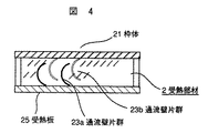
図3、及び図4はともに受熱部材2の流路の構成に関して異なる実施形態を示す断面図である。
図2に示されるように、受熱部材2は冷媒液を通流するための空間部を形成して空間部を密封する枠体21と受熱板25を有し、枠体21に対向形成されている側辺部の一方には冷媒液の流出口22aが設けられ、他方には冷媒液の流入口22bが設けている。各々の流出口22a,流入口22bには冷媒液を循環するための配管7が接続されている。枠体21の内部の空間部には、冷媒液を分流して通流するためのほぼ並行に設置された通流壁片群23と、通流壁片群23と流出口22a,流入口22bを設けた側辺部の内壁間に冷媒液を合流あるいは分流するための空間となるヘッダ24a,24bと、を有するように構成された受熱板25を組み込んで接合され、受熱部材2として密封構成されている。
FIG. 2 is a schematic configuration perspective view (partially perspective view) in the embodiment of the heat receiving member 2 of the present invention.
3 and 4 are cross-sectional views showing different embodiments regarding the configuration of the flow path of the heat receiving member 2.
As shown in FIG. 2, the heat receiving member 2 includes a frame body 21 and a heat receiving plate 25 that form a space portion for allowing the refrigerant liquid to flow therethrough and seal the space portion. One of the side portions is provided with a refrigerant liquid outlet 22a, and the other is provided with a refrigerant liquid inlet 22b. A pipe 7 for circulating the refrigerant liquid is connected to each of the outlet 22a and the inlet 22b. In the space inside the frame 21, a flow wall piece group 23, which is arranged substantially in parallel for diverting and flowing the refrigerant liquid, a flow wall piece group 23, an outlet 22 a, and an inlet 22 b. A heat receiving plate 25 configured to have a header 24a, 24b serving as a space for merging or diverting the refrigerant liquid between the inner walls of the side portions provided with the heat receiving plate 25 is joined and joined to form a sealed structure as the heat receiving member 2 Has been.
さらには、図3に示すように、通流壁片群23は通流する冷媒液との接触面積を広くとるために、ほぼ並行に配した壁平面を受熱部材2の厚さ方向の中間部で湾曲した形状に形成している。このことは冷媒液と通流壁片群23との熱伝導量を高めながら薄型の受熱部材2の強度を増す構成と成されている。尚、この通流壁片群23は一般的に熱伝導性の良い受熱板25の板材質と同一の材質で構成されることが好ましいことから、切削加工による切り起し構造が最適とされる。しかし、他の構造によって流路を形成しても支障はない。 Furthermore, as shown in FIG. 3, in order to increase the contact area of the flow wall piece group 23 with the flowing refrigerant liquid, the wall plane arranged substantially in parallel is an intermediate portion in the thickness direction of the heat receiving member 2. It is formed in a curved shape. This is configured to increase the strength of the thin heat receiving member 2 while increasing the amount of heat conduction between the refrigerant liquid and the flow wall piece group 23. In addition, since it is preferable that this flow-through-wall piece group 23 is generally comprised with the same material as the board | plate material of the heat receiving board 25 with favorable heat conductivity, the cut-and-raised structure by cutting is made optimal. . However, there is no problem even if the flow path is formed by another structure.
一方、切削加工による切り起し通流壁片群23の端部は加工状態によって湾曲状態や、切り起し長にばらつきが生じる可能性があり、一方向からの切り起し片で構成した流路では枠体21の内壁上平面との間で隙間が生じて冷媒液の短絡した流路バイパスができることになる場合がある。この隙間の発生を回避するためには切削加工後に高さ位置を揃える後処理作業等が必要になる。この問題を回避する方法として、図4にみるように、枠体
21の受熱面と対向する内壁上平面に形成した通流壁片群23bと、受熱板25に形成された通流壁片群23aとを上下より、相互に組込ませて対向配置する構成として流路を形成すると対向した通流壁片によって、短絡した流路バイパスが形成されることがないので、この高さ位置を揃える作業を割愛することができる。
On the other hand, the end portion of the cut and raised flow wall piece group 23 by cutting may vary in the curved state and the cut and raised length depending on the processing state, and the flow constituted by the cut and raised pieces from one direction. On the road, there may be a flow path bypass in which a gap is generated between the plane on the inner wall of the frame body 21 and the refrigerant liquid is short-circuited. In order to avoid the generation of this gap, post-processing work for aligning the height position after cutting is required. As a method of avoiding this problem, as shown in FIG. 4, a flow wall piece group 23 b formed on the inner wall upper surface facing the heat receiving surface of the frame body 21, and a flow wall piece group formed on the heat receiving plate 25. When the flow path is formed as a configuration in which the upper and lower portions are integrated with each other from the upper and lower sides, a short-circuited flow path bypass is not formed by the opposed flow wall pieces. Can be omitted.
この構造による受熱部材2は、電子機器に搭載された複数の半導体部品の発熱体1に熱的に接続して用いることで、発熱体1の発生熱を受熱部材2内部に通流する冷媒液によって蒸気冷媒への相変化を伴いながら受熱させる。さらには、発熱体1から受熱した冷媒液が蒸気冷媒となる場合には、受熱部材2の枠体21の内壁上平面部に蒸気冷媒が上昇するため枠体21の内壁上平面に形成した通流壁片群23bは冷却フィンとしての作用をも成すことができる。なお、当該壁面外部に放熱手段を形成することにより、さらに通流壁片群23bによる冷却効果が有効になることは言うまでもない。 The heat receiving member 2 having this structure is a refrigerant liquid that allows heat generated in the heat generating member 1 to flow into the heat receiving member 2 by being thermally connected to the heat generating members 1 of a plurality of semiconductor components mounted on the electronic device. Heat is received with the phase change to the vapor refrigerant. Further, when the refrigerant liquid received from the heating element 1 becomes a vapor refrigerant, the vapor refrigerant rises to the upper flat surface portion of the inner wall of the frame 21 of the heat receiving member 2, so that the passage formed on the inner wall upper surface of the frame 21. The flow wall piece group 23b can also function as a cooling fin. Needless to say, the cooling effect of the flow wall piece group 23b becomes more effective by forming the heat radiation means outside the wall surface.
さらに、通流壁片群23は、切り起こしにより湾曲形状に構成されると、根本部分において壁面に対し鋭角部が形成され液の表面張力による液保持機能が大きくなる。従って、液の蒸発による液枯れ現象が回避され安定で高性能な冷却が可能となる。 Furthermore, when the flow wall piece group 23 is formed in a curved shape by cutting and raising, an acute angle portion is formed with respect to the wall surface at the root portion, and the liquid holding function by the surface tension of the liquid is increased. Therefore, the liquid depletion phenomenon due to the evaporation of the liquid is avoided, and stable and high-performance cooling is possible.
受熱部材2において受熱した冷媒液はポンプ6により駆動され循環される。駆動ポンプ6は、液冷媒と蒸気冷媒の混合状態にある冷媒液を駆動する状態の場合には、容積型ポンプであることが好ましいが、液冷媒を駆動する場合には遠心ポンプでもよい。また、駆動ポンプ6の取り付け位置は、循環される冷媒液の状態から放熱部の下流に配置されることが一般的であるが、駆動ポンプ種類を考慮すれば放熱部の上流に置かれてもよい。 The refrigerant liquid received by the heat receiving member 2 is driven and circulated by the pump 6. The drive pump 6 is preferably a positive displacement pump when driving a refrigerant liquid in a mixed state of a liquid refrigerant and a vapor refrigerant, but may be a centrifugal pump when driving a liquid refrigerant. Further, the mounting position of the drive pump 6 is generally arranged downstream of the heat radiating portion from the state of the circulated refrigerant liquid, but even if it is placed upstream of the heat radiating portion in consideration of the type of the drive pump. Good.
受熱した冷媒液は、気液混合体流入口43から放熱部材4に流入して、放熱部材4内部に配置された流路を通流しながら冷却されて蒸気冷媒とされた冷却液は液冷媒に相変化される。 The received refrigerant liquid flows into the heat radiating member 4 from the gas-liquid mixture inlet 43, and the cooling liquid cooled and vaporized while flowing through the flow path disposed inside the heat radiating member 4 becomes liquid refrigerant. Phase change.
図5は放熱部材4と一体のタンク5を示す概略外観斜視図である。
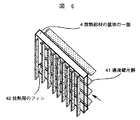
図6は放熱部材の枠体の一部を示す斜視図である。
図において、放熱部材4は、内部に冷却液の通流する通流壁片群41を有している。また、放熱部材4の外表面の一部には、放熱用のフィン42を有している。これらの通流壁片群41、及び放熱用のフィン42は、受熱部材2において説明した切り起し加工によるものであっても良いし、他の従来方法による放熱管等のものであっても支障ない。ただ、本発明の蒸気冷媒の冷却による液冷媒への相変化を行う放熱部材4の流路としては、放熱効果を有するフィン状の流路で支障ないために熱伝導性の良い放熱板43の材質を切削加工した切り起し片の通流壁片群41が最適な構造であるといえる。
FIG. 5 is a schematic external perspective view showing the tank 5 integrated with the heat radiating member 4.
FIG. 6 is a perspective view showing a part of the frame of the heat radiating member.
In the figure, the heat radiating member 4 has a flow wall piece group 41 through which a coolant flows. A part of the outer surface of the heat radiating member 4 has a
さらに放熱部材4の外部表面の一部には、放熱効果をあげるための放熱用フィンを同様に切削加工によって設けることも可能である。放熱部材4の上部とタンク5の下部とは冷却液を通流できる貫通口43aを有した仕切り板43によって分割されているが、液層と蒸気層を分離するための仕切り板である必要はない。また、仕切り板43の放熱部側の表面には、蒸気冷媒と接触する通流壁片群(フィン)を形成してタンク5の筐体を放熱のための放熱板の作用として利用することも可能である。放熱部材4に外表面に形成された放熱用フィンによる冷却性能を向上するために放熱用フィンに向けてファンによって送風する構成は容易に想定される方法である。 Furthermore, a part of the outer surface of the heat radiating member 4 may be provided with a heat radiating fin for enhancing the heat radiating effect by cutting. The upper part of the heat dissipating member 4 and the lower part of the tank 5 are divided by a partition plate 43 having a through-hole 43a through which the coolant can flow, but it is necessary to be a partition plate for separating the liquid layer and the vapor layer. Absent. Further, on the surface of the partition plate 43 on the heat radiating portion side, a flow wall piece group (fin) that comes into contact with the vapor refrigerant is formed, and the casing of the tank 5 can be used as an action of the heat radiating plate for heat radiation. Is possible. In order to improve the cooling performance by the heat radiating fin formed on the outer surface of the heat radiating member 4, a configuration in which air is blown by the fan toward the heat radiating fin is an easily assumed method.
次に、放熱部材と一体構成とされたタンク部の上部に配置された放熱部材4の一側壁面には冷媒液の流入口43を設け、下部のタンク5の一側面壁にはタンク5から冷媒液を流出するための流出口51を設けている。この構成によって放熱部材4により冷却された冷媒液を一旦液冷媒としてタンク5に溜めて流出口51から循環されるために、タンク5の下流で、受熱部材2の上流に位置して配置されたポンプ6によって冷媒液が駆動される。 Next, a refrigerant liquid inflow port 43 is provided on one side wall surface of the heat radiating member 4 disposed on the upper portion of the tank portion integrated with the heat radiating member, and the tank 5 is provided on one side wall of the lower tank 5. An outlet 51 is provided for flowing out the refrigerant liquid. With this configuration, the refrigerant liquid cooled by the heat radiating member 4 is temporarily stored as a liquid refrigerant in the tank 5 and circulated from the outlet 51, so that it is disposed downstream of the tank 5 and upstream of the heat receiving member 2. The refrigerant liquid is driven by the pump 6.
ポンプ6により、放熱された冷媒液を受熱部材2に送り受熱部材2によって再び発熱体1の熱が受熱される。これらのサイクルを繰り返すために冷媒液を循環可能なように各部材は配管で密封接続されている。 The pump 6 sends the radiated refrigerant liquid to the heat receiving member 2 and the heat receiving member 2 receives the heat of the heating element 1 again. In order to repeat these cycles, each member is hermetically connected by piping so that the refrigerant liquid can be circulated.
本発明によれば、熱交換器内部に設けられた通流壁片群が伝熱性の良い材質による薄型形状で冷媒液との接触面積を増す形状に構成されることで冷媒の熱伝導性の向上が図られる。また、この通流壁片群の加工方法による形状の不整形についても2つの通流壁片群を相互に組み込ませて対向配置することで流路を形成することによって、バイパスを形成することの流路を構成できる。さらには、伝導性の良い同一材質を利用した冷却用のフィンを形成した熱交換器とすることで冷却性能の向上がより図られる。熱伝導性を考慮した同一材質への加工方法の容易性等を活用した冷媒液の流路や、冷却用のフィンを形成した高性能な熱交換器の実現により気液混合の冷媒液を循環するに好適な冷却装置を小型で簡易に提供できることから、色々な形態の電子機器に搭載可能となる。 According to the present invention, the flow wall piece group provided inside the heat exchanger is configured to have a thin shape made of a material having good heat conductivity and a shape that increases the contact area with the refrigerant liquid, so that the heat conductivity of the refrigerant is improved. Improvement is achieved. In addition, regarding the irregular shape by the processing method of the flow wall piece group, it is possible to form a bypass by forming a flow path by incorporating the two flow wall piece groups into each other and opposingly arranging them. A flow path can be configured. Furthermore, the cooling performance can be further improved by using a heat exchanger in which cooling fins using the same conductive material are formed. Circulating refrigerant liquid in a gas-liquid mixture by realizing a high-performance heat exchanger with cooling liquid fins and cooling fins that make use of the ease of processing into the same material in consideration of thermal conductivity Therefore, since a suitable cooling device can be easily provided in a small size, it can be mounted on various types of electronic devices.
1…発熱体、2…受熱部材、4…放熱部材、5…タンク、6…ポンプ、7…配管。 DESCRIPTION OF SYMBOLS 1 ... Heat generating body, 2 ... Heat receiving member, 4 ... Heat radiating member, 5 ... Tank, 6 ... Pump, 7 ... Piping.
Claims (4)
前記第1および第2の熱交換器は内部に冷媒液を通流する流路を設け、少なくとも枠体で密封する構成とし、少なくとも前記第1の熱交換器における冷媒液を通流する前記流路は熱伝導性の良い材質によって構成される受熱或いは放熱を行う熱交換基板に、この熱交換基板の平面部から立ち上げた通流壁片群を前記熱交換基板と一体にして、前記冷媒液の通流方向に並行に形成し、かつ該通流壁片群の壁平面の各々を根本部分において壁面に対し鋭角部が形成されるように湾曲平面に構成したことを特徴とする電子機器用の冷却装置。 Regarding cooling of a heating element in an electronic device, a first heat exchanger having a flow path of a refrigerant liquid therein and receiving heat by being connected to the heating element, and a refrigerant liquid received by the first heat exchanger A second heat exchanger for cooling, a tank section for storing the refrigerant liquid flowing through the second heat exchanger, and a pump for driving the refrigerant liquid, the first heat exchanger; In the cooling device in which the second heat exchanger, the tank unit, and the pump are connected by piping to form a circulation flow path,
The first and second heat exchangers are provided with a flow path through which the refrigerant liquid flows and are sealed with at least a frame, and at least the flow through which the refrigerant liquid flows in the first heat exchanger. The path is a heat exchange board configured to receive heat or dissipate heat composed of a material having good heat conductivity, and a flow wall piece group raised from the flat portion of the heat exchange board is integrated with the heat exchange board , An electron characterized in that it is formed in parallel with the flow direction of the refrigerant liquid , and each of the wall planes of the flow wall piece group is formed in a curved plane so that an acute angle portion is formed with respect to the wall surface at the root portion. Cooling device for equipment.
前記冷媒液は、前記第1の熱交換器によって受熱されて気液混合状態とされ、前記第2の熱交換器によって液化状態とされることを特徴とする電子機器用の冷却装置。 In the cooling device for electronic devices according to claim 1,
The cooling device for electronic equipment, wherein the refrigerant liquid is received by the first heat exchanger to be in a gas-liquid mixed state and is liquefied by the second heat exchanger.
前記第1の熱交換器では、前記通流壁片群を形成した前記熱交換基板と前記枠体の前記熱交換基板に対向した内壁面に第2の通流壁片群を形成し、前記熱交換基板に形成された第1の通流壁片群と前記第2の通流壁片群を互いの通流壁平面が対向するように組み込ませて配置して前記冷媒液を通流する前記流路を構成としたことを特徴とする電子機器用の冷却装置。 In the cooling device for electronic devices in any one of Claims 1 thru | or 2,
In the first heat exchanger, a second flow wall piece group is formed on the heat exchange substrate that forms the flow wall piece group and an inner wall surface of the frame that faces the heat exchange substrate, The first flow wall piece group formed on the heat exchange substrate and the second flow wall piece group are arranged so as to face each other through the flow wall planes, and the refrigerant liquid is flowed therethrough. A cooling apparatus for electronic equipment, characterized in that the flow path is configured.
前記第2の熱交換器を構成する前記熱交換基板あるいは前記枠体の外壁面の一部に冷却用のフィンを一体に形成したことを特徴とする電子機器用の冷却装置。 In the cooling device for electronic devices in any one of Claims 1 thru | or 3,
A cooling apparatus for electronic equipment, wherein a cooling fin is integrally formed on a part of an outer wall surface of the heat exchange substrate or the frame body constituting the second heat exchanger.
Priority Applications (1)
| Application Number | Priority Date | Filing Date | Title |
|---|---|---|---|
| JP2006027838A JP4682858B2 (en) | 2006-02-06 | 2006-02-06 | Cooling device for electronic equipment |
Applications Claiming Priority (1)
| Application Number | Priority Date | Filing Date | Title |
|---|---|---|---|
| JP2006027838A JP4682858B2 (en) | 2006-02-06 | 2006-02-06 | Cooling device for electronic equipment |
Publications (3)
| Publication Number | Publication Date |
|---|---|
| JP2007208154A JP2007208154A (en) | 2007-08-16 |
| JP2007208154A5 JP2007208154A5 (en) | 2009-03-12 |
| JP4682858B2 true JP4682858B2 (en) | 2011-05-11 |
Family
ID=38487329
Family Applications (1)
| Application Number | Title | Priority Date | Filing Date |
|---|---|---|---|
| JP2006027838A Expired - Fee Related JP4682858B2 (en) | 2006-02-06 | 2006-02-06 | Cooling device for electronic equipment |
Country Status (1)
| Country | Link |
|---|---|
| JP (1) | JP4682858B2 (en) |
Families Citing this family (5)
| Publication number | Priority date | Publication date | Assignee | Title |
|---|---|---|---|---|
| JP2012038010A (en) * | 2010-08-05 | 2012-02-23 | Fujitsu Ltd | Heat receiver, liquid cooling unit and electronic device |
| JP2014075563A (en) * | 2012-10-02 | 2014-04-24 | Nakamura Mfg Co Ltd | Boiling heat transfer surface for ebullient cooler and forming method thereof |
| JP6503909B2 (en) * | 2015-06-12 | 2019-04-24 | 株式会社デンソー | Semiconductor device |
| CN109227977A (en) * | 2018-10-25 | 2019-01-18 | 天津职业技术师范大学 | Semiconductor cooling flushing system |
| CN113163696A (en) * | 2021-05-13 | 2021-07-23 | 黑龙江祥辉通信工程有限公司 | Automatic heat dissipation communication device based on 5G |
Citations (4)
| Publication number | Priority date | Publication date | Assignee | Title |
|---|---|---|---|---|
| JP2001077566A (en) * | 1999-09-07 | 2001-03-23 | Matsushita Electric Ind Co Ltd | Cooling element |
| JP2001352020A (en) * | 2000-06-06 | 2001-12-21 | Ricchisutoon:Kk | Manufacturing method of heat radiating element |
| JP2002110878A (en) * | 2000-09-28 | 2002-04-12 | Matsushita Refrig Co Ltd | Cooling module and cooling system comprising it |
| JP2005079337A (en) * | 2003-08-29 | 2005-03-24 | Toshiba Corp | Liquid cooled apparatus and system thereof |
Family Cites Families (2)
| Publication number | Priority date | Publication date | Assignee | Title |
|---|---|---|---|---|
| JPH0368892A (en) * | 1989-08-07 | 1991-03-25 | Takashige Yokoyama | Timer for competition |
| JP3654326B2 (en) * | 1996-11-25 | 2005-06-02 | 株式会社デンソー | Boiling cooler |
-
2006
- 2006-02-06 JP JP2006027838A patent/JP4682858B2/en not_active Expired - Fee Related
Patent Citations (4)
| Publication number | Priority date | Publication date | Assignee | Title |
|---|---|---|---|---|
| JP2001077566A (en) * | 1999-09-07 | 2001-03-23 | Matsushita Electric Ind Co Ltd | Cooling element |
| JP2001352020A (en) * | 2000-06-06 | 2001-12-21 | Ricchisutoon:Kk | Manufacturing method of heat radiating element |
| JP2002110878A (en) * | 2000-09-28 | 2002-04-12 | Matsushita Refrig Co Ltd | Cooling module and cooling system comprising it |
| JP2005079337A (en) * | 2003-08-29 | 2005-03-24 | Toshiba Corp | Liquid cooled apparatus and system thereof |
Also Published As
| Publication number | Publication date |
|---|---|
| JP2007208154A (en) | 2007-08-16 |
Similar Documents
| Publication | Publication Date | Title |
|---|---|---|
| JP4682859B2 (en) | Cooling system for electronic equipment | |
| JP4997215B2 (en) | Server device | |
| JP5644767B2 (en) | Heat transport structure of electronic equipment | |
| JP3994948B2 (en) | Cooling device and electronic equipment | |
| US7613001B1 (en) | Heat dissipation device with heat pipe | |
| EP1708263B1 (en) | Cooling jacket | |
| JP4532422B2 (en) | Heat sink with centrifugal fan | |
| JP4550664B2 (en) | Heat sink with heat pipe | |
| US8355253B2 (en) | Electronic apparatus with heat dissipation device | |
| US20080023176A1 (en) | Heat dissipation device | |
| JP2004116864A (en) | Electronic apparatus comprising cooling mechanism | |
| JP6126149B2 (en) | Air-cooled laser apparatus provided with a heat conducting member having a radiation fin | |
| US20070227699A1 (en) | Method, apparatus and system for flow distribution through a heat exchanger | |
| US20070251675A1 (en) | Thermal module | |
| US20100025013A1 (en) | Heat dissipation device | |
| JP2002368468A (en) | Heat sink, its manufacturing method and cooler using the same | |
| US20100032141A1 (en) | cooling system utilizing carbon nanotubes for cooling of electrical systems | |
| JP4682858B2 (en) | Cooling device for electronic equipment | |
| JP5667739B2 (en) | Heat sink assembly, semiconductor module, and semiconductor device with cooling device | |
| JP5192797B2 (en) | heatsink | |
| TWI501719B (en) | Heat dissipation device | |
| EP2801781B1 (en) | Cooling device | |
| JP2006237366A (en) | Heat sink | |
| JP2009088051A (en) | Cooling device for electronic instrument | |
| JP3805723B2 (en) | Electronic device cooling system |
Legal Events
| Date | Code | Title | Description |
|---|---|---|---|
| A521 | Request for written amendment filed |
Free format text: JAPANESE INTERMEDIATE CODE: A523 Effective date: 20090123 |
|
| A621 | Written request for application examination |
Free format text: JAPANESE INTERMEDIATE CODE: A621 Effective date: 20090123 |
|
| A977 | Report on retrieval |
Free format text: JAPANESE INTERMEDIATE CODE: A971007 Effective date: 20100624 |
|
| A131 | Notification of reasons for refusal |
Free format text: JAPANESE INTERMEDIATE CODE: A131 Effective date: 20100706 |
|
| A521 | Request for written amendment filed |
Free format text: JAPANESE INTERMEDIATE CODE: A523 Effective date: 20100901 |
|
| TRDD | Decision of grant or rejection written | ||
| A01 | Written decision to grant a patent or to grant a registration (utility model) |
Free format text: JAPANESE INTERMEDIATE CODE: A01 Effective date: 20110111 |
|
| A01 | Written decision to grant a patent or to grant a registration (utility model) |
Free format text: JAPANESE INTERMEDIATE CODE: A01 |
|
| A61 | First payment of annual fees (during grant procedure) |
Free format text: JAPANESE INTERMEDIATE CODE: A61 Effective date: 20110124 |
|
| FPAY | Renewal fee payment (event date is renewal date of database) |
Free format text: PAYMENT UNTIL: 20140218 Year of fee payment: 3 |
|
| R151 | Written notification of patent or utility model registration |
Ref document number: 4682858 Country of ref document: JP Free format text: JAPANESE INTERMEDIATE CODE: R151 |
|
| FPAY | Renewal fee payment (event date is renewal date of database) |
Free format text: PAYMENT UNTIL: 20140218 Year of fee payment: 3 |
|
| S111 | Request for change of ownership or part of ownership |
Free format text: JAPANESE INTERMEDIATE CODE: R313111 |
|
| R350 | Written notification of registration of transfer |
Free format text: JAPANESE INTERMEDIATE CODE: R350 |
|
| S111 | Request for change of ownership or part of ownership |
Free format text: JAPANESE INTERMEDIATE CODE: R313111 |
|
| R350 | Written notification of registration of transfer |
Free format text: JAPANESE INTERMEDIATE CODE: R350 |
|
| R250 | Receipt of annual fees |
Free format text: JAPANESE INTERMEDIATE CODE: R250 |
|
| R250 | Receipt of annual fees |
Free format text: JAPANESE INTERMEDIATE CODE: R250 |
|
| R250 | Receipt of annual fees |
Free format text: JAPANESE INTERMEDIATE CODE: R250 |
|
| S111 | Request for change of ownership or part of ownership |
Free format text: JAPANESE INTERMEDIATE CODE: R313111 |
|
| R350 | Written notification of registration of transfer |
Free format text: JAPANESE INTERMEDIATE CODE: R350 |
|
| LAPS | Cancellation because of no payment of annual fees |