US12107617B2 - RF filter for use at 5G frequencies - Google Patents
RF filter for use at 5G frequencies Download PDFInfo
- Publication number
- US12107617B2 US12107617B2 US18/311,280 US202318311280A US12107617B2 US 12107617 B2 US12107617 B2 US 12107617B2 US 202318311280 A US202318311280 A US 202318311280A US 12107617 B2 US12107617 B2 US 12107617B2
- Authority
- US
- United States
- Prior art keywords
- filter
- polymer composition
- polymer
- antenna
- aromatic
- Prior art date
- Legal status (The legal status is an assumption and is not a legal conclusion. Google has not performed a legal analysis and makes no representation as to the accuracy of the status listed.)
- Active
Links
Images


Classifications
-
- H—ELECTRICITY
- H04—ELECTRIC COMMUNICATION TECHNIQUE
- H04B—TRANSMISSION
- H04B1/00—Details of transmission systems, not covered by a single one of groups H04B3/00 - H04B13/00; Details of transmission systems not characterised by the medium used for transmission
- H04B1/38—Transceivers, i.e. devices in which transmitter and receiver form a structural unit and in which at least one part is used for functions of transmitting and receiving
- H04B1/40—Circuits
- H04B1/403—Circuits using the same oscillator for generating both the transmitter frequency and the receiver local oscillator frequency
- H04B1/405—Circuits using the same oscillator for generating both the transmitter frequency and the receiver local oscillator frequency with multiple discrete channels
-
- H—ELECTRICITY
- H03—ELECTRONIC CIRCUITRY
- H03H—IMPEDANCE NETWORKS, e.g. RESONANT CIRCUITS; RESONATORS
- H03H9/00—Networks comprising electromechanical or electro-acoustic elements; Electromechanical resonators
- H03H9/02—Details
- H03H9/02007—Details of bulk acoustic wave devices
- H03H9/02015—Characteristics of piezoelectric layers, e.g. cutting angles
-
- H—ELECTRICITY
- H04—ELECTRIC COMMUNICATION TECHNIQUE
- H04B—TRANSMISSION
- H04B1/00—Details of transmission systems, not covered by a single one of groups H04B3/00 - H04B13/00; Details of transmission systems not characterised by the medium used for transmission
- H04B1/02—Transmitters
- H04B1/04—Circuits
- H04B1/0458—Arrangements for matching and coupling between power amplifier and antenna or between amplifying stages
-
- H—ELECTRICITY
- H01—ELECTRIC ELEMENTS
- H01P—WAVEGUIDES; RESONATORS, LINES, OR OTHER DEVICES OF THE WAVEGUIDE TYPE
- H01P11/00—Apparatus or processes specially adapted for manufacturing waveguides or resonators, lines, or other devices of the waveguide type
- H01P11/007—Manufacturing frequency-selective devices
-
- H—ELECTRICITY
- H01—ELECTRIC ELEMENTS
- H01Q—ANTENNAS, i.e. RADIO AERIALS
- H01Q1/00—Details of, or arrangements associated with, antennas
- H01Q1/12—Supports; Mounting means
- H01Q1/22—Supports; Mounting means by structural association with other equipment or articles
- H01Q1/24—Supports; Mounting means by structural association with other equipment or articles with receiving set
- H01Q1/241—Supports; Mounting means by structural association with other equipment or articles with receiving set used in mobile communications, e.g. GSM
- H01Q1/246—Supports; Mounting means by structural association with other equipment or articles with receiving set used in mobile communications, e.g. GSM specially adapted for base stations
-
- H—ELECTRICITY
- H01—ELECTRIC ELEMENTS
- H01Q—ANTENNAS, i.e. RADIO AERIALS
- H01Q21/00—Antenna arrays or systems
- H01Q21/06—Arrays of individually energised antenna units similarly polarised and spaced apart
- H01Q21/061—Two dimensional planar arrays
- H01Q21/065—Patch antenna array
-
- H—ELECTRICITY
- H03—ELECTRONIC CIRCUITRY
- H03H—IMPEDANCE NETWORKS, e.g. RESONANT CIRCUITS; RESONATORS
- H03H9/00—Networks comprising electromechanical or electro-acoustic elements; Electromechanical resonators
- H03H9/02—Details
- H03H9/05—Holders or supports
- H03H9/10—Mounting in enclosures
- H03H9/1007—Mounting in enclosures for bulk acoustic wave [BAW] devices
-
- H—ELECTRICITY
- H04—ELECTRIC COMMUNICATION TECHNIQUE
- H04B—TRANSMISSION
- H04B1/00—Details of transmission systems, not covered by a single one of groups H04B3/00 - H04B13/00; Details of transmission systems not characterised by the medium used for transmission
- H04B1/02—Transmitters
- H04B1/04—Circuits
-
- H—ELECTRICITY
- H04—ELECTRIC COMMUNICATION TECHNIQUE
- H04B—TRANSMISSION
- H04B1/00—Details of transmission systems, not covered by a single one of groups H04B3/00 - H04B13/00; Details of transmission systems not characterised by the medium used for transmission
- H04B1/06—Receivers
- H04B1/10—Means associated with receiver for limiting or suppressing noise or interference
- H04B1/1018—Means associated with receiver for limiting or suppressing noise or interference noise filters connected between the power supply and the receiver
-
- H—ELECTRICITY
- H04—ELECTRIC COMMUNICATION TECHNIQUE
- H04B—TRANSMISSION
- H04B1/00—Details of transmission systems, not covered by a single one of groups H04B3/00 - H04B13/00; Details of transmission systems not characterised by the medium used for transmission
- H04B1/06—Receivers
- H04B1/16—Circuits
- H04B1/18—Input circuits, e.g. for coupling to an antenna or a transmission line
-
- H—ELECTRICITY
- H03—ELECTRONIC CIRCUITRY
- H03H—IMPEDANCE NETWORKS, e.g. RESONANT CIRCUITS; RESONATORS
- H03H9/00—Networks comprising electromechanical or electro-acoustic elements; Electromechanical resonators
- H03H9/02—Details
- H03H9/02007—Details of bulk acoustic wave devices
- H03H9/02047—Treatment of substrates
-
- H—ELECTRICITY
- H03—ELECTRONIC CIRCUITRY
- H03H—IMPEDANCE NETWORKS, e.g. RESONANT CIRCUITS; RESONATORS
- H03H9/00—Networks comprising electromechanical or electro-acoustic elements; Electromechanical resonators
- H03H9/02—Details
- H03H9/02535—Details of surface acoustic wave devices
- H03H9/02543—Characteristics of substrate, e.g. cutting angles
- H03H9/02574—Characteristics of substrate, e.g. cutting angles of combined substrates, multilayered substrates, piezoelectrical layers on not-piezoelectrical substrate
-
- H—ELECTRICITY
- H03—ELECTRONIC CIRCUITRY
- H03H—IMPEDANCE NETWORKS, e.g. RESONANT CIRCUITS; RESONATORS
- H03H9/00—Networks comprising electromechanical or electro-acoustic elements; Electromechanical resonators
- H03H9/02—Details
- H03H9/05—Holders or supports
- H03H9/10—Mounting in enclosures
- H03H9/1064—Mounting in enclosures for surface acoustic wave [SAW] devices
Definitions
- Radiofrequency (“RF”) interference is a significant issue for any wireless communication platform.
- RF filters e.g., acoustic filters, cavity filters, etc.
- 2G, 3G, and 4G wireless access methods in up to 15 bands, as well as Wi-Fi, Bluetooth and the receive path of GPS receivers.
- Wi-Fi Wireless Fidelity
- Bluetooth Wireless Fidelity
- an RF filter that comprises a resonator element and a polymer composition.
- the polymer composition contains an aromatic polymer and has a melting temperature of about 240° C. or more.
- the polymer composition exhibits a dielectric constant of about 5 or less and dissipation factor of about 0.05 or less at a frequency of 10 GHz.
- FIG. 1 depicts one embodiment of a 5G antenna system that can be employed in the present invention
- FIG. 2 A illustrates a top-down view of an example user computing device including 5G antennas
- FIG. 2 B illustrates a side elevation view of the example user computing device of FIG. 2 A ;
- FIG. 3 illustrates an enlarged view of a portion of the user computing device of FIG. 2 A ;
- FIG. 4 illustrates a side elevation view of co-planar waveguide antenna array configuration that can be employed in a 5G antenna system
- FIG. 5 A illustrates an antenna array for massive multiple-in-multiple-out configurations of a 5G antenna system
- FIG. 5 B illustrates an antenna array formed that can be employed in a 5G antenna system
- FIG. 5 C illustrates an example antenna configuration that can be employed in a 5G antenna system
- FIG. 6 is a schematic view of one embodiment an RF SAW filter that may be employed in the present invention.
- FIG. 7 is a schematic view of one embodiment of an RF BAW filter for use in the present invention.
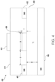
- FIG. 8 is a schematic view of one embodiment of another embodiment of an RF SAW filter that may be employed in the present invention.
- FIG. 9 is a schematic view of one embodiment of an RF cavity filter that may be employed in the present invention.
- the present invention is directed to a radiofrequency filter (“RF”) for use in 5G applications, such as an acoustic filter or cavity filter.
- the RF filter typically includes one or more resonator elements (e.g., piezoelectric material, dielectric material, etc.), which can produce resonant behavior over a narrow frequency band in the desired 5G frequency, such as about 2.5 GHz or higher, in some embodiments about 3.0 GHz or higher, in some embodiments from about 3 GHz to about 300 GHz, or higher, in some embodiments from about 4 GHz to about 80 GHz, in some embodiments from about 5 GHz to about 80 GHz, in some embodiments from about 20 GHz to about 80 GHz, and in some embodiments from about 28 GHz to about 60 GHz.
- resonator elements e.g., piezoelectric material, dielectric material, etc.
- a polymer composition is employed in the RF filter (e.g., substrate, housing, etc.) that exhibits a low dielectric constant and dissipation factor over a wide range of frequencies, making it particularly suitable for use in 5G applications. That is, the polymer composition may exhibit a low dielectric constant of about 5 or less, in some embodiments about 4.5 or less, in some embodiments from about 0.1 to about 4.4 and in some embodiments, from about 1 to about 4.2, in some embodiments, from about 1.5 to about 4, in some embodiments from about 2 to about 3.9, and in some embodiments, from about 3.5 to about 3.9 over typical 5G frequencies (e.g., 2 or 10 GHz).
- the RF filter e.g., substrate, housing, etc.
- the polymer composition may exhibit a low dielectric constant of about 5 or less, in some embodiments about 4.5 or less, in some embodiments from about 0.1 to about 4.4 and in some embodiments, from about 1 to about 4.2, in some embodiments, from about 1.5 to
- the dissipation factor of the polymer composition which is a measure of the loss rate of energy, may likewise be about 0.05 or less, in some embodiments about 0.01 or less, in some embodiments from about 0.0001 to about 0.008, and in some embodiments from about 0.0002 to about 0.006 over typical 5G frequencies (e.g., 2 or 10 GHz).
- the dissipation factor may be very low, such as about 0.003 or less, in some embodiments about 0.002 or less, in some embodiments about 0.001 or less, in some embodiments, about 0.0009 or less, in some embodiments about 0.0008 or less, and in some embodiments, from about 0.0001 to about 0.0007 over typical 5G frequencies (e.g., 2 or 10 GHz).
- the melting temperature of the polymer composition may, for instance, be about 240° C. or more, in some embodiments about 260° C., in some embodiments from about 280° C. to about 400° C., and in some embodiments, from about 250° C. to about 380° C.
- the ratio of the deflection temperature under load (“DTUL”), a measure of short term heat resistance, to the melting temperature may still remain relatively high.
- the ratio may range from about 0.5 to about 1.00, in some embodiments from about 0.6 to about 0.95, and in some embodiments from about 0.65 to about 0.85.
- the specific DTUL values may, for instance, be about 200° C. or more, in some embodiments from about 200° C. to about 350° C., in some embodiments from about 210° C. to about 320° C., and in some embodiments from about 230° C. to about 310° C.
- Such high DTUL values can, among other things, allow the use of high speed and reliable surface mounting processes for mating the structure with other components of the electrical component.
- the polymer composition may also possess excellent mechanical properties.
- the polymer composition may exhibit a tensile strength of about 10 MPa or more, in some embodiments about 50 MPa or more, in some embodiments from about 70 MPa to about 300 MPa, and in some embodiments from about 80 MPa to about 200 MPa.
- the polymer composition may exhibit a tensile elongation of about 0.3% or more, in some embodiments about 0.4% or more, in some embodiments from about 0.5% to about 4%, and in some embodiments from about 0.5% to about 2%.
- the polymer composition may exhibit a tensile modulus of about 5,000 MPa or more, in some embodiments about 6,000 MPa or more, in some embodiments about 7,000 MPa to about 25,000 MPa, and in some embodiments from about 10,000 MPa to about 20,000 MPa.
- the tensile properties may be determined at a temperature of 23° C. in accordance with ISO Test No. 527:2012.
- the polymer composition may exhibit a flexural strength of about 20 MPa or more, in some embodiments about 30 MPa or more, in some embodiments about 50 MPa or more, in some embodiments from about 70 MPa to about 300 MPa, and in some embodiments from about 80 MPa to about 200 MPa.
- the polymer composition may exhibit a flexural elongation of about 0.4% or more, in some embodiments from about 0.5% to about 4%, and in some embodiments from about 0.5% to about 2%.
- the polymer composition may exhibit a flexural modulus of about 5,000 MPa or more, in some embodiments about 6,000 MPa or more, in some embodiments about 7,000 MPa to about 25,000 MPa, and in some embodiments from about 10,000 MPa to about 20,000 MPa.
- the flexural properties may be determined at a temperature of 23° C. in accordance with 178:2010.
- the polymer composition may also possess a high impact strength, which may be useful when forming thin substrates.
- the polymer composition may, for instance, possess a Charpy notched impact strength of about 3 kJ/m 2 or more, in some embodiments about 5 kJ/m 2 or more, in some embodiments about 7 kJ/m 2 or more, in some embodiments from about 8 kJ/m 2 to about 40 kJ/m 2 , and in some embodiments from about 10 kJ/m 2 to about 25 kJ/m 2 .
- the impact strength may be determined at a temperature of 23° C. in accordance with ISO Test No. ISO 179-1:2010.
- the polymer composition contains one or more aromatic polymers.
- Such polymers are generally considered “high performance” polymers in that they are selected to have a relatively high glass transition temperature and/or high melting temperature such that they provide a substantial degree of heat resistance to the polymer composition.
- the polymer may have a melting temperature of about 240° C. or more, in some embodiments about 260° C., in some embodiments from about 280° C. to about 400° C., and in some embodiments, from about 250° C. to about 380° C.
- the aromatic polymer may also have a glass transition temperature of about 30° C. or more, in some embodiments about 40° C. or more, in some embodiments from about 50° C.
- the glass transition and melting temperatures may be determined as is well known in the art using differential scanning calorimetry (“DSC”), such as determined by ISO Test No. 11357-2:2013 (glass transition) and 11357-3:2011 (melting).
- DSC differential scanning calorimetry
- Polyarylene sulfides are suitable semi-crystalline aromatic polymers for use in the polymer composition.
- the polyarylene sulfide may be homopolymers or copolymers.
- selective combination of dihaloaromatic compounds can result in a polyarylene sulfide copolymer containing not less than two different units.
- a polyarylene sulfide copolymer can be formed containing segments having the structure of formula:
- the polyarylene sulfide may be linear, semi-linear, branched or crosslinked.
- Linear polyarylene sulfides typically contain 80 mol % or more of the repeating unit —(Ar—S)—.
- Such linear polymers may also include a small amount of a branching unit or a cross-linking unit, but the amount of branching or cross-linking units is typically less than about 1 mol % of the total monomer units of the polyarylene sulfide.
- a linear polyarylene sulfide polymer may be a random copolymer or a block copolymer containing the above-mentioned repeating unit.
- Semi-linear polyarylene sulfides may likewise have a cross-linking structure or a branched structure introduced into the polymer a small amount of one or more monomers having three or more reactive functional groups.
- monomer components used in forming a semi-linear polyarylene sulfide can include an amount of polyhaloaromatic compounds having two or more halogen substituents per molecule which can be utilized in preparing branched polymers.
- Such monomers can be represented by the formula R′X n , where each X is selected from chlorine, bromine, and iodine, n is an integer of 3 to 6, and R′ is a polyvalent aromatic radical of valence n which can have up to about 4 methyl substituents, the total number of carbon atoms in R′ being within the range of 6 to about 16.
- Examples of some polyhaloaromatic compounds having more than two halogens substituted per molecule that can be employed in forming a semi-linear polyarylene sulfide include 1,2,3-trichlorobenzene, 1,2,4-trichlorobenzene, 1,3-dichloro-5-bromobenzene, 1,2,4-triiodobenzene, 1,2,3,5-tetrabromobenzene, hexachlorobenzene, 1,3,5-trichloro-2,4,6-trimethylbenzene, 2,2′,4,4′-tetrachlorobiphenyl, 2,2′,5,5′-tetra-iodobiphenyl, 2,2′,6,6′-tetrabromo-3,3′,5,5′-tetramethylbiphenyl, 1,2,3,4-tetrachloronaphthalene, 1,2,4-tribromo-6-methylnaphthalene, etc., and mixtures thereof.
- crystalline polymers may also be employed in the polymer composition.
- Particularly suitable are liquid crystalline polymers, which have a high degree of crystallinity that enables them to effectively fill small spaces.
- Liquid crystalline polymers are generally classified as “thermotropic” to the extent that they can possess a rod-like structure and exhibit a crystalline behavior in their molten state (e.g., thermotropic nematic state).
- the liquid crystalline polymers employed in the polymer composition typically have a melting temperature of from about 200° C. to about 400° C., in some embodiments from about 250° C. to about 380° C., in some embodiments from about 270° C. to about 360° C., and in some embodiments from about 300° C. to about 350° C.
- Such polymers may be formed from one or more types of repeating units as is known in the art.
- a liquid crystalline polymer may, for example, contain one or more aromatic ester repeating units generally represented by the following Formula (I):
- ring B is a substituted or unsubstituted 6-membered aryl group (e.g., 1,4-phenylene or 1,3-phenylene), a substituted or unsubstituted 6-membered aryl group fused to a substituted or unsubstituted 5- or 6-membered aryl group (e.g., 2,6-naphthalene), or a substituted or unsubstituted 6-membered aryl group linked to a substituted or unsubstituted 5- or 6-membered aryl group (e.g., 4,4-biphenylene); and
- Y 1 and Y 2 are independently O, C(O), NH, C(O)HN, or NHC(O).
- Y 1 and Y 2 are C(O).
- aromatic ester repeating units may include, for instance, aromatic dicarboxylic repeating units (Y 1 and Y 2 in Formula I are C(O)), aromatic hydroxycarboxylic repeating units (Y 1 is O and Y 2 is C(O) in Formula I), as well as various combinations thereof.
- Aromatic hydroxycarboxylic repeating units may be employed that are derived from aromatic hydroxycarboxylic acids, such as, 4-hydroxybenzoic acid; 4-hydroxy-4′-biphenylcarboxylic acid; 2-hydroxy-6-naphthoic acid; 2-hydroxy-5-naphthoic acid; 3-hydroxy-2-naphthoic acid; 2-hydroxy-3-naphthoic acid; 4′-hydroxyphenyl-4-benzoic acid; 3′-hydroxyphenyl-4-benzoic acid; 4′-hydroxyphenyl-3-benzoic acid, etc., as well as alkyl, alkoxy, aryl and halogen substituents thereof, and combination thereof.
- aromatic hydroxycarboxylic acids such as, 4-hydroxybenzoic acid; 4-hydroxy-4′-biphenylcarboxylic acid; 2-hydroxy-6-naphthoic acid; 2-hydroxy-5-naphthoic acid; 3-hydroxy-2-naphthoic acid; 2-
- aromatic hydroxycarboxylic acids are 4-hydroxybenzoic acid (“HBA”) and 6-hydroxy-2-naphthoic acid (“HNA”).
- HBA 4-hydroxybenzoic acid
- HNA 6-hydroxy-2-naphthoic acid
- repeating units derived from hydroxycarboxylic acids typically constitute about 40 mol. % or more, in some embodiments about 50 mole % or more, in some embodiments from about 55 mol. % to 100 mol. %, and in some embodiments, from about 60 mol. % to about 95 mol. % of the polymer.
- Aromatic dicarboxylic repeating units may also be employed that are derived from aromatic dicarboxylic acids, such as terephthalic acid, isophthalic acid, 2,6-naphthalenedicarboxylic acid, diphenyl ether-4,4′-dicarboxylic acid, 1,6-naphthalenedicarboxylic acid, 2,7-naphthalenedicarboxylic acid, 4,4′-dicarboxybiphenyl, bis(4-carboxyphenyl)ether, bis(4-carboxyphenyl)butane, bis(4-carboxyphenyl)ethane, bis(3-carboxyphenyl)ether, bis(3-carboxyphenyl)ethane, etc., as well as alkyl, alkoxy, aryl and halogen substituents thereof, and combinations thereof.
- aromatic dicarboxylic acids such as terephthalic acid, isophthalic acid, 2,6-naphthalenedicarboxylic acid
- aromatic dicarboxylic acids may include, for instance, terephthalic acid (“TA”), isophthalic acid (“IA”), and 2,6-naphthalenedicarboxylic acid (“NDA”).
- TA terephthalic acid
- IA isophthalic acid
- NDA 2,6-naphthalenedicarboxylic acid
- repeating units derived from aromatic dicarboxylic acids typically constitute from about 1 mol. % to about 40 mol. %, in some embodiments from about 2 mol. % to about 30 mol. %, and in some embodiments, from about 5 mol. % to about 25% of the polymer.
- repeating units may also be employed in the polymer.
- repeating units may be employed that are derived from aromatic diols, such as hydroquinone, resorcinol, 2,6-dihydroxynaphthalene, 2,7-dihydroxynaphthalene, 1,6-dihydroxynaphthalene, 4,4′-dihydroxybiphenyl (or 4,4′-biphenol), 3,3′-dihydroxybiphenyl, 3,4′-dihydroxybiphenyl, 4,4′-dihydroxybiphenyl ether, bis(4-hydroxyphenyl)ethane, etc., as well as alkyl, alkoxy, aryl and halogen substituents thereof, and combinations thereof.
- aromatic diols such as hydroquinone, resorcinol, 2,6-dihydroxynaphthalene, 2,7-dihydroxynaphthalene, 1,6-dihydroxynaphthalene, 4,4′-dihydroxybiphen
- aromatic diols may include, for instance, hydroquinone (“HQ”) and 4,4′-biphenol (“BP”).
- HQ hydroquinone
- BP 4,4′-biphenol
- repeating units derived from aromatic diols typically constitute from about 1 mol. % to about 40 mol. %, in some embodiments from about 2 mol. % to about 30 mol. %, and in some embodiments, from about 5 mol. % to about 25% of the polymer.
- Repeating units may also be employed, such as those derived from aromatic amides (e.g., acetaminophen (“APAP”)) and/or aromatic amines (e.g., 4-aminophenol (“AP”), 3-aminophenol, 1,4-phenylenediamine, 1,3-phenylenediamine, etc.).
- aromatic amides e.g., APAP
- aromatic amines e.g., AP
- repeating units derived from aromatic amides (e.g., APAP) and/or aromatic amines (e.g., AP) typically constitute from about 0.1 mol. % to about 20 mol. %, in some embodiments from about 0.5 mol. % to about 15 mol. %, and in some embodiments, from about 1 mol. % to about 10% of the polymer.
- the polymer may contain one or more repeating units derived from non-aromatic monomers, such as aliphatic or cycloaliphatic hydroxycarboxylic acids, dicarboxylic acids, diols, amides, amines, etc.
- non-aromatic monomers such as aliphatic or cycloaliphatic hydroxycarboxylic acids, dicarboxylic acids, diols, amides, amines, etc.
- the polymer may be “wholly aromatic” in that it lacks repeating units derived from non-aromatic (e.g., aliphatic or cycloaliphatic) monomers.
- the liquid crystalline polymer may be a “high naphthenic” polymer to the extent that it contains a relatively high content of repeating units derived from naphthenic hydroxycarboxylic acids and naphthenic dicarboxylic acids, such as NDA, HNA, or combinations thereof. That is, the total amount of repeating units derived from naphthenic hydroxycarboxylic and/or dicarboxylic acids (e.g., NDA, HNA, or a combination of HNA and NDA) is typically about 10 mol. % or more, in some embodiments about 12 mol. % or more, in some embodiments about 15 mol. % or more, in some embodiments about 18 mol.
- % or more in some embodiments about 20 mol. % or more, in some embodiments about 30 mol. % or more, in some embodiments about 40 mol. % or more, in some embodiments about 45 mol. % or more, in some embodiments about 50 mol. % or more, in some embodiments about 60 mol. % or more, in some embodiments about 62 mol. % or more, in some embodiments about 68 mol. % or more, in some embodiments about 70 mol. % or more, and in some embodiments, from about 70 mol. % to about 80 mol. % of the polymer.
- high naphthenic polymers are capable of reducing the tendency of the polymer composition to absorb water, which can help stabilize the dielectric constant and dissipation factor at high frequency ranges.
- high naphthenic polymers typically have a water adsorption of about 0.015% or less, in some embodiments about 0.01% or less, and in some embodiments, from about 0.0001% to about 0.008% after being immersed in water for 24 hours in accordance with ISO 62-1:2008.
- the high naphthenic polymers may also have a moisture adsorption of about 0.01% or less, in some embodiments about 0.008% or less, and in some embodiments, from about 0.0001% to about 0.006% after being exposed to a humid atmosphere (50% relative humidity) at a temperature of 23° C. in accordance with ISO 62-4:2008.
- the repeating units derived from HNA may constitute 30 mol. % or more, in some embodiments about 40 mol. % or more, in some embodiments about 45 mol. % or more, in some embodiments 50 mol. % or more, in some embodiments about 60 mol. % or more, in some embodiments about 62 mol. % or more, in some embodiments about 68 mol. % or more, in some embodiments about 70 mol. % or more, and in some embodiments, from about 70 mol. % to about 80 mol. % of the polymer.
- the liquid crystalline polymer may also contain various other monomers.
- the polymer may contain repeating units derived from HBA in an amount of from about 10 mol. % to about 40 mol. %, and in some embodiments from about 15 mol. % to about 35 mol. %, and in some embodiments, from about 20 mol. % to about 30 mol. %.
- the molar ratio of HNA to HBA may be selectively controlled within a specific range to help achieve the desired properties, such as from about 0.1 to about 40, in some embodiments from about 0.5 to about 20, in some embodiments from about 0.8 to about 10, and in some embodiments, from about 1 to about 5.
- the polymer may also contain aromatic dicarboxylic acid(s) (e.g., IA and/or TA) in an amount of from about 1 mol. % to about 40 mol. %, and in some embodiments, from about 5 mol. % to about 25 mol. %; and/or aromatic diol(s) (e.g., BP and/or HQ) in an amount of from about 1 mol. % to about 40 mol. %, and in some embodiments, from about 5 mol. % to about 25 mol. %. In some cases, however, it may be desired to minimize the presence of such monomers in the polymer to help achieve the desired properties.
- aromatic dicarboxylic acid(s) e.g., IA and/or TA
- aromatic diol(s) e.g., BP and/or HQ
- the total amount of aromatic dicarboxylic acid(s) may be about 20 mol % or less, in some embodiments about 15 mol. % or less, in some embodiments about 10 mol. % or less, in some embodiments, from 0 mol. % to about 5 mol. %, and in some embodiments, from 0 mol. % to about 2 mol. % of the polymer.
- the total amount of aromatic dicarboxylic acid(s) e.g., IA and/or TA
- % or less in some embodiments, from 0 mol. % to about 5 mol. %, and in some embodiments, from 0 mol. % to about 2 mol. % of the polymer (e.g., 0 mol. %).
- the repeating units derived from NDA may constitute 10 mol. % or more, in some embodiments about 12 mol. % or more, in some embodiments about 15 mol. % or more, and in some embodiments, from about 18 mol. % to about 95 mol. % of the polymer.
- the liquid crystalline polymer may also contain various other monomers, such as aromatic hydroxycarboxylic acid(s) (e.g., HBA) in an amount of from about 20 mol. % to about 60 mol. %, and in some embodiments, from about 30 mol. % to about 50 mol.
- aromatic dicarboxylic acid(s) e.g., IA and/or TA
- aromatic diol(s) e.g., BP and/or HQ
- the liquid crystalline polymer may be prepared by initially introducing the aromatic monomer(s) used to form the ester repeating units (e.g., aromatic hydroxycarboxylic acid, aromatic dicarboxylic acid, etc.) and/or other repeating units (e.g., aromatic diol, aromatic amide, aromatic amine, etc.) into a reactor vessel to initiate a polycondensation reaction.
- aromatic monomer(s) used to form the ester repeating units e.g., aromatic hydroxycarboxylic acid, aromatic dicarboxylic acid, etc.
- other repeating units e.g., aromatic diol, aromatic amide, aromatic amine, etc.
- the vessel employed for the reaction is not especially limited, although it is typically desired to employ one that is commonly used in reactions of high viscosity fluids.
- a reaction vessel may include a stirring tank-type apparatus that has an agitator with a variably-shaped stirring blade, such as an anchor type, multistage type, spiral-ribbon type, screw shaft type, etc., or a modified shape thereof.
- Further examples of such a reaction vessel may include a mixing apparatus commonly used in resin kneading, such as a kneader, a roll mill, a Banbury mixer, etc.
- the reaction may proceed through the acetylation of the monomers as known the art. This may be accomplished by adding an acetylating agent (e.g., acetic anhydride) to the monomers.
- acetylation is generally initiated at temperatures of about 90° C.
- reflux may be employed to maintain vapor phase temperature below the point at which acetic acid byproduct and anhydride begin to distill. Temperatures during acetylation typically range from between 90° C. to 150° C., and in some embodiments, from about 110° C. to about 150° C. If reflux is used, the vapor phase temperature typically exceeds the boiling point of acetic acid, but remains low enough to retain residual acetic anhydride.
- acetic anhydride vaporizes at temperatures of about 140° C.
- providing the reactor with a vapor phase reflux at a temperature of from about 110° C. to about 130° C. is particularly desirable.
- an excess amount of acetic anhydride may be employed. The amount of excess anhydride will vary depending upon the particular acetylation conditions employed, including the presence or absence of reflux. The use of an excess of from about 1 to about 10 mole percent of acetic anhydride, based on the total moles of reactant hydroxyl groups present is not uncommon.
- Acetylation may occur in in a separate reactor vessel, or it may occur in situ within the polymerization reactor vessel.
- one or more of the monomers may be introduced to the acetylation reactor and subsequently transferred to the polymerization reactor.
- one or more of the monomers may also be directly introduced to the reactor vessel without undergoing pre-acetylation.
- a catalyst may be optionally employed, such as metal salt catalysts (e.g., magnesium acetate, tin(I) acetate, tetrabutyl titanate, lead acetate, sodium acetate, potassium acetate, etc.) and organic compound catalysts (e.g., N-methylimidazole).
- metal salt catalysts e.g., magnesium acetate, tin(I) acetate, tetrabutyl titanate, lead acetate, sodium acetate, potassium acetate, etc.
- organic compound catalysts e.g., N-methylimidazole
- the reaction mixture is generally heated to an elevated temperature within the polymerization reactor vessel to initiate melt polycondensation of the reactants.
- Polycondensation may occur, for instance, within a temperature range of from about 250° C. to about 380° C., and in some embodiments, from about 280° C. to about 380° C.
- one suitable technique for forming the aromatic polyester may include charging precursor monomers and acetic anhydride into the reactor, heating the mixture to a temperature of from about 90° C. to about 150° C. to acetylize a hydroxyl group of the monomers (e.g., forming acetoxy), and then increasing the temperature to from about 280° C. to about 380° C. to carry out melt polycondensation.
- volatile byproducts of the reaction may also be removed so that the desired molecular weight may be readily achieved.
- the reaction mixture is generally subjected to agitation during polymerization to ensure good heat and mass transfer, and in turn, good material homogeneity.
- the rotational velocity of the agitator may vary during the course of the reaction, but typically ranges from about 10 to about 100 revolutions per minute (“rpm”), and in some embodiments, from about 20 to about 80 rpm.
- the polymerization reaction may also be conducted under vacuum, the application of which facilitates the removal of volatiles formed during the final stages of polycondensation.
- the vacuum may be created by the application of a suctional pressure, such as within the range of from about 5 to about 30 pounds per square inch (“psi”), and in some embodiments, from about 10 to about 20 psi.
- the molten polymer may be discharged from the reactor, typically through an extrusion orifice fitted with a die of desired configuration, cooled, and collected. Commonly, the melt is discharged through a perforated die to form strands that are taken up in a water bath, pelletized and dried. In some embodiments, the melt polymerized polymer may also be subjected to a subsequent solid-state polymerization method to further increase its molecular weight. Solid-state polymerization may be conducted in the presence of a gas (e.g., air, inert gas, etc.).
- a gas e.g., air, inert gas, etc.
- Suitable inert gases may include, for instance, include nitrogen, helium, argon, neon, krypton, xenon, etc., as well as combinations thereof.
- the solid-state polymerization reactor vessel can be of virtually any design that will allow the polymer to be maintained at the desired solid-state polymerization temperature for the desired residence time. Examples of such vessels can be those that have a fixed bed, static bed, moving bed, fluidized bed, etc.
- the temperature at which solid-state polymerization is performed may vary, but is typically within a range of from about 250° C. to about 350° C.
- the polymerization time will of course vary based on the temperature and target molecular weight. In most cases, however, the solid-state polymerization time will be from about 2 to about 12 hours, and in some embodiments, from about 4 to about 10 hours.
- the total amount of liquid crystalline polymers employed in the polymer composition may be from about 40 wt. % to about 99 wt. %, in some embodiments from about 50 wt. % to about 98 wt. %, and in some embodiments, from about 60 wt. % to about 95 wt. % of the entire polymer composition.
- all of the liquid crystalline polymers are “high naphthenic” polymers such as described above.
- “low naphthenic” liquid crystalline polymers may also be employed in the composition in which the total amount of repeating units derived from naphthenic hydroxycarboxylic and/or dicarboxylic acids (e.g., NDA, HNA, or a combination of HNA and NDA) is less than 10 mol. %, in some embodiments about 8 mol. % or less, in some embodiments about 6 mol. % or less, and in some embodiments, from about 1 mol. % to about 5 mol. % of the polymer. In certain embodiments, it may be desired that the low naphthenic polymers are present in only a relatively low amount.
- naphthenic hydroxycarboxylic and/or dicarboxylic acids e.g., NDA, HNA, or a combination of HNA and NDA
- low naphthenic liquid crystalline polymers typically constitute from about 1 wt. % to about 50 wt. %, in some embodiments from about 2 wt. % to about 40 wt. %, and in some embodiments, from about 5 wt. % to about 30 wt. % of the total amount of liquid crystalline polymers in the composition, and from about 0.5 wt. % to about 45 wt. %, in some embodiments from about 2 wt. % to about 35 wt. %, and in some embodiments, from about 5 wt. % to about 25 wt. % of the entire composition.
- high naphthenic liquid crystalline polymers typically constitute from about 50 wt. % to about 99 wt. %, in some embodiments from about 60 wt. % to about 98 wt. %, and in some embodiments, from about 70 wt. % to about 95 wt. % of the total amount of liquid crystalline polymers in the composition, and from about 55 wt. % to about 99.5 wt. %, in some embodiments from about 65 wt. % to about 98 wt. %, and in some embodiments, from about 75 wt. % to about 95 wt. % of the entire composition.
- Aromatic polymer(s) may be employed in neat form within a polymer composition (i.e., 100 wt. % of the polymer composition), or a wide variety of other additives may optionally be included within the composition.
- additives typically constitute from about 1 wt. % to about 60 wt. %, in some embodiments from about 2 wt. % to about 50 wt. %, and in some embodiments, from about 5 wt. % to about 40 wt. % of the polymer composition.
- liquid crystalline polymers may likewise constitute from about 40 wt. % to about 99 wt. %, in some embodiments from about 50 wt. % to about 98 wt. %, and in some embodiments, from about 60 wt. % to about 95 wt. % of the polymer composition.
- a wide variety of additional optional additives can also be included in the polymer composition, such as laser activatable additives, fibrous fillers, particulate fillers, hollow fillers, hydrophobic materials, lubricants, thermally conductive fillers, pigments, antioxidants, stabilizers, surfactants, waxes, flame retardants, anti-drip additives, nucleating agents (e.g., boron nitride), flow modifiers, coupling agents, antimicrobials, pigments or other colorants, impact modifiers, dielectric material, and other materials added to enhance properties and processability.
- Such optional materials may be employed in polymer composition in conventional amounts and according to conventional processing techniques.
- the polymer composition may be “laser activatable” in the sense that it contains an additive that can be activated by a laser direct structuring (“LDS”) process.
- LDS laser direct structuring
- the additive is exposed to a laser that causes the release of metals.
- the laser draws the pattern of conductive elements onto the part and leaves behind a roughened surface containing embedded metal particles. These particles act as nuclei for the crystal growth during a subsequent plating process (e.g., copper plating, gold plating, nickel plating, silver plating, zinc plating, tin plating, etc.).
- the laser activatable additive generally includes spinel crystals, which may include two or more metal oxide cluster configurations within a definable crystal formation.
- the overall crystal formation may have the following general formula: AB 2 O 4
- A is a metal cation having a valance of 2, such as cadmium, chromium, manganese, nickel, zinc, copper, cobalt, iron, magnesium, tin, titanium, etc., as well as combinations thereof; and
- B is a metal cation having a valance of 3, such as chromium, iron, aluminum, nickel, manganese, tin, etc., as well as combinations thereof.
- a in the formula above provides the primary cation component of a first metal oxide cluster and B provides the primary cation component of a second metal oxide cluster.
- These oxide clusters may have the same or different structures.
- the first metal oxide cluster has a tetrahedral structure and the second metal oxide cluster has an octahedral cluster.
- the clusters may together provide a singular identifiable crystal type structure having heightened susceptibility to electromagnetic radiation.
- Suitable spinel crystals include, for instance, MgAl 2 O 4 , ZnAl 2 O 4 , FeAl 2 O 4 , CuFe 2 O 4 , CuCr 2 O 4 , MnFe 2 O 4 , NiFe 2 O 4 , TiFe 2 O 4 , FeCr 2 O 4 , MgCr 2 O 4 , etc.
- Copper chromium oxide (CuCr 2 O 4 ) is particularly suitable for use in the present invention and is available from Shepherd Color Co. under the designation “Shepherd Black 1GM.”
- Laser activatable additives may constitute from about 0.1 wt. % to about 30 wt. %, in some embodiments from about 0.5 wt. % to about 20 wt. %, and in some embodiments, from about 1 wt. % to about 10 wt. % of the polymer composition.
- such high strength fibers may be formed from materials that are generally insulative in nature, such as glass, ceramics or minerals (e.g., alumina or silica), aramids (e.g., Kevlar® marketed by E. I. duPont de Nemours, Wilmington, Del.), minerals, polyolefins, polyesters, etc.
- materials that are generally insulative in nature such as glass, ceramics or minerals (e.g., alumina or silica), aramids (e.g., Kevlar® marketed by E. I. duPont de Nemours, Wilmington, Del.), minerals, polyolefins, polyesters, etc.
- the fibrous filler may include glass fibers, mineral fibers, or a mixture thereof.
- the fibrous filler may include glass fibers.
- the glass fibers particularly suitable may include E-glass, A-glass, C-glass, D-glass, AR-glass, R-glass, S1-glass, S2-glass, etc.
- the fibrous filler may include mineral fibers.
- the mineral fibers may include those derived from silicates, such as neosilicates, sorosilicates, inosilicates (e.g., calcium inosilicates, such as wollastonite; calcium magnesium inosilicates, such as tremolite; calcium magnesium iron inosilicates, such as actinolite; magnesium iron inosilicates, such as anthophyllite; etc.), phyllosilicates (e.g., aluminum phyllosilicates, such as palygorskite), tectosilicates, etc.; sulfates, such as calcium sulfates (e.g., dehydrated or anhydrous gypsum); mineral wools (e.g., rock or slag wool); and so forth.
- silicates such as neosilicates, sorosilicates, inosilicates (e.g., calcium inosilicates, such as wo
- fibrous fillers may have a variety of different sizes, fibers having a certain aspect ratio can help improve the mechanical properties of the polymer composition. That is, fibrous fillers having an aspect ratio (average length divided by nominal diameter) of about 2 or more, in some embodiments about 4 or more, in some embodiments from about 5 to about 50, and in some embodiments from about 8 to about 40 may be particularly beneficial. Such fibrous fillers may, for instance, have a weight average length of about 10 micrometer or more, in some embodiments about 25 micrometers or more, in some embodiments from about 50 micrometers or more to about 800 micrometers or less, and in some embodiments from about 60 micrometers to about 500 micrometers.
- such fibrous fillers may, for instance, have a volume average length of about 10 micrometer or more, in some embodiments about 25 micrometers or more, in some embodiments from about 50 micrometers or more to about 800 micrometers or less, and in some embodiments from about 60 micrometers to about 500 micrometers.
- the fibrous fillers may likewise have a nominal diameter of about 5 micrometers or more, in some embodiments about 6 micrometers or more, in some embodiments from about 8 micrometers to about 40 micrometers, and in some embodiments from about 9 micrometers to about 20 micrometers.
- the relative amount of the fibrous filler may also be selectively controlled to help achieve the desired mechanical and thermal properties without adversely impacting other properties of the polymer composition, such as its flowability and dielectric properties, etc.
- the fibrous fillers may have a dielectric constant of about 6 or less, in some embodiments about 5.5 or less, in some embodiments from about 1.1 to about 5, and in some embodiments from about 2 to about 4.8 at a frequency of 1 GHz.
- the fibrous filler may be in a modified or an unmodified form, e.g. provided with a sizing, or chemically treated, in order to improve adhesion to the plastic.
- glass fibers may be provided with a sizing to protect the glass fiber, to smooth the fiber but also to improve the adhesion between the fiber and a matrix material.
- a sizing may comprise silanes, film forming agents, lubricants, wetting agents, adhesive agents optionally antistatic agents and plasticizers, emulsifiers and optionally further additives.
- the sizing may include a silane. Specific examples of silanes are aminosilanes, e.g.
- 3-trimethoxysilylpropylamine N-(2-aminoethyl)-3-aminopropyltrimethoxy-silane, N-(3-trimethoxysilanylpropyl)ethane-1,2-diamine, 3-(2-aminoethyl-amino)propyltrimethoxysilane, N-[3-(trimethoxysilyl)propyl]-1,2-ethane-diamine.
- the fibrous filler may, for instance, constitute from about 1 wt. % to about 40 wt. %, in some embodiments from about 3 wt. % to about 30 wt. %, and in some embodiments, from about 5 wt. % to about 20 wt. % of the polymer composition.
- the polymer composition may also include one or more hollow inorganic fillers to help achieve the desired dielectric constant.
- such fillers may have a dielectric constant of about 3.0 or less, in some embodiments about 2.5 or less, in some embodiments from about 1.1 to about 2.3, and in some embodiments from about 1.2 to about 2.0 at 100 MHz.
- the hollow inorganic fillers typically have an interior hollow space or cavity and may be synthesized using techniques known in the art.
- the hollow inorganic fillers may be made from conventional materials.
- the hollow inorganic fillers may include alumina, silica, zirconia, magnesia, glass, fly ash, borate, phosphate, ceramic, and the like.
- the hollow inorganic fillers may include hollow glass fillers, hollow ceramic fillers, and mixtures thereof. In one embodiment, the hollow inorganic fillers include hollow glass fillers.
- the hollow glass fillers may be made from a soda lime borosilicate glass, a soda lime glass, a borosilicate glass, a sodium borosilicate glass, a sodium silicate glass, or an aluminosilicate glass.
- the composition of the glass may be at least about 65% by weight of SiO 2 , 3-15% by weight of Na 2 O, 8-15% by weight of CaO, 0.1-5% by weight of MgO, 0.01-3% by weight of Al 2 O 3 , 0.01-1% by weight of K 2 O, and optionally other oxides (e.g., Li 2 O, Fe 2 O 3 , TiO 2 , B 2 O 3 ).
- the composition may be about 50-58% by weight of SiO 2 , 25-30% by weight of Al 2 O 3 , 6-10% by weight of CaO, 1-4% by weight of Na 2 O/K 2 O, and 1-5% by weight of other oxides.
- the hollow glass fillers may include more alkaline earth metal oxides than alkali metal oxides.
- the weight ratio of the alkaline earth metal oxides to the alkali metal oxides may be more than 1, in some embodiments about 1.1 or more, in some embodiments about 1.2 to about 4, and in some embodiments from about 1.5 to about 3.
- the glass composition may vary depending on the type of glass utilized and still provide the benefits as desired by the present invention.
- the hollow inorganic fillers may have at least one dimension having an average value that is about 1 micrometers or more, in some embodiments about 5 micrometers or more, in some embodiments about 8 micrometers or more, in some embodiments from about 1 micrometer to about 150 micrometers, in some embodiments from about 10 micrometers to about 150 micrometers, and in some embodiments from about 12 micrometers to about 50 micrometers.
- such average value may refer to a d50 value.
- the hollow inorganic fillers may have a Dio of about 3 micrometers or more, in some embodiments about 4 micrometers or more, in some embodiments from about 5 micrometers to about 20 micrometers, and in some embodiments from about 6 micrometers to about 15 micrometers.
- the hollow inorganic fillers may have a D90 of about 10 micrometers or more, in some embodiments about 15 micrometers or more, in some embodiments from about 20 micrometers to about 150 micrometers, and in some embodiments from about 22 micrometers to about 50 micrometers.
- the hollow inorganic fillers may be present in a size distribution, which may be a Gaussian, normal, or non-normal size distribution.
- the hollow inorganic fillers may have a Gaussian size distribution.
- the hollow inorganic fillers may have a normal size distribution.
- the hollow inorganic fillers may have a non-normal size distribution.
- non-normal size distributions may include unimodal and multi-modal (e.g., bimodal) size distributions.
- such dimension may be any dimension. In one embodiment, however, such dimension refers to a diameter.
- such value for the dimension refers to an average diameter of spheres.
- the dimension, such as the average diameter may be determined in accordance to 3M QCM 193.0.
- the hollow inorganic fillers may be referring to hollow spheres such as hollow glass spheres.
- the hollow inorganic fillers may have an average aspect ratio of approximately 1. In general, the average aspect ratio may be about 0.8 or more, in some embodiments about 0.85 or more, in some embodiments from about 0.9 to about 1.3, and in some embodiments from about 0.95 to about 1.05.
- the hollow inorganic fillers may have relatively thin walls to help with the dielectric properties of the polymer composition as well as the reduction in weight.
- the thickness of the wall may be about 50% or less, in some embodiments about 40% or less, in some embodiments from about 1% to about 30%, and in some embodiments from about 2% to about 25% the average dimension, such as the average diameter, of the hollow inorganic fillers.
- the hollow inorganic fillers may have a certain true density that can allow for easy handling and provide a polymer composition having a reduction in weight.
- the true density refers to the quotient obtained by dividing the mass of a sample of the hollow fillers by the true volume of that mass of hollow fillers wherein the true volume is referred to as the aggregate total volume of the hollow fillers.
- the true density of the hollow inorganic fillers may be about 0.1 g/cm 3 or more, in some embodiments about 0.2 g/cm 3 or more, in some embodiments from about 0.3 g/cm 3 or more to about 1.2 g/cm 3 , and in some embodiments from about 0.4 g/cm 3 or more to about 0.9 g/cm 3 .
- the true density may be determined in accordance to 3M QCM 14.24.1.
- the fillers are hollow, they may have a mechanical strength that allows for maintaining the integrity of the structure of the fillers resulting in a lower likelihood of the fillers being broken during processing and/or use.
- the isotactic crush resistance (i.e., wherein at least 80 vol. %, such as at least 90 vol. % of the hollow fillers survive) of the hollow inorganic fillers may be about 20 MPa or more, in some embodiments about 100 MPa or more, in some embodiments from about 150 MPa to about 500 MPa, and in some embodiments from about 200 MPa to about 350 MPa.
- the isotactic crush resistance may be determined in accordance to 3M QCM 14.1.8.
- the alkalinity of the hollow inorganic fillers may be about 1.0 meq/g or less, in some embodiments about 0.9 meq/g or less, in some embodiments from about 0.1 meq/g to about 0.8 meq/g, and in some embodiments from about 0.2 meq/g to about 0.7 meq/g.
- the alkalinity may be determined in accordance to 3M QCM 55.19.
- the hollow inorganic fillers may be treated with a suitable acid, such as a phosphoric acid.
- the hollow inorganic fillers may also include a surface treatment to assist with providing a better compatibility with the polymer and/or other components within the polymer composition.
- the surface treatment may be a silanization.
- the surface treatment agents may include, but are not limited to, aminosilanes, epoxysilanes, etc.
- the hollow inorganic fillers may, for instance, constitute about 1 wt. % or more, in some embodiments about 4 wt. % or more, in some embodiments from about 5 wt. % to about 40 wt. %, and in some embodiments from about 10 wt. % to about 30 wt. % of the polymer composition.
- a particulate filler may be employed for improving certain properties of the polymer composition.
- the particulate filler may be employed in the polymer composition in an amount of from about 5 to about 60 parts, in some embodiments from about 10 to about 50 parts, and in some embodiments, from about 15 to about 40 parts by weight per 100 parts of the aromatic polymer(s) employed in the polymer composition.
- the particulate filler may constitute from about 5 wt. % to about 50 wt. %, in some embodiments from about 10 wt. % to about 40 wt. %, and in some embodiments, from about 15 wt. % to about 30 wt. % of the polymer composition.
- particles may be employed that have a certain hardness value to help improve the surface properties of the composition.
- the hardness values may be about 2 or more, in some embodiments about 2.5 or more, in some embodiments from about 3 to about 11, in some embodiments from about 3.5 to about 11, and in some embodiments, from about 4.5 to about 6.5 based on the Mohs hardness scale.
- Such particles may include, for instance, silica (Mohs hardness of 7), mica (e.g., Mohs hardness of about 3); carbonates, such as calcium carbonate (CaCO3, Mohs hardness of 3.0) or a copper carbonate hydroxide (Cu 2 CO 3 (OH) 2 , Mohs hardness of 4.0); fluorides, such as calcium fluoride (CaFl 2 , Mohs hardness of 4.0); phosphates, such as calcium pyrophosphate ((Ca 2 P 2 O 7 , Mohs hardness of 5.0), anhydrous dicalcium phosphate (CaHPO 4 , Mohs hardness of 3.5), or hydrated aluminum phosphate (AlPO 4 ⁇ 2H 2 O, Mohs hardness of 4.5); borates, such as calcium borosilicate hydroxide (Ca 2 B 5 SiO 9 (OH) 5 , Mohs hardness of 3.5); alumina (AlO 2 , Mohs
- the shape of the particles may vary as desired.
- flake-shaped particles may be employed in certain embodiments that have a relatively high aspect ratio (e.g., average diameter divided by average thickness), such as about 10:1 or more, in some embodiments about 20:1 or more, and in some embodiments, from about 40:1 to about 200:1.
- the average diameter of the particles may, for example, range from about 5 micrometers to about 200 micrometers, in some embodiments from about 30 micrometers to about 150 micrometers, and in some embodiments, from about 50 micrometers to about 120 micrometers, such as determined using laser diffraction techniques in accordance with ISO 13320:2009 (e.g., with a Horiba LA-960 particle size distribution analyzer).
- Suitable flaked-shaped particles may be formed from a natural and/or synthetic silicate mineral, such as mica, halloysite, kaolinite, illite, montmorillonite, vermiculite, palygorskite, pyrophyllite, calcium silicate, aluminum silicate, wollastonite, etc. Mica, for instance, is particularly suitable.
- a natural and/or synthetic silicate mineral such as mica, halloysite, kaolinite, illite, montmorillonite, vermiculite, palygorskite, pyrophyllite, calcium silicate, aluminum silicate, wollastonite, etc. Mica, for instance, is particularly suitable.
- any form of mica may generally be employed, including, for instance, muscovite (KAl 2 (AlSi 3 )O 10 (OH) 2 ), biotite (K(Mg,Fe) 3 (AlSi 3 )O 10 (OH) 2 ), phlogopite (KMg 3 (AlSi 3 )O 10 (OH) 2 ), lepidolite (K(Li,Al) 2-3 (AlSi 3 )O 10 (OH) 2 ), glauconite (K,Na)(Al,Mg,Fe) 2 (Si,Al) 4 O 10 (OH) 2 ), etc.
- Granular particles may also be employed.
- such particles have an average diameter of from about 0.1 to about 10 micrometers, in some embodiments from about 0.2 to about 4 micrometers, and in some embodiments, from about 0.5 to about 2 micrometers, such as determined using laser diffraction techniques in accordance with ISO 13320:2009 (e.g., with a Horiba LA-960 particle size distribution analyzer).
- Particularly suitable granular fillers may include, for instance, talc, barium sulfate, calcium sulfate, calcium carbonate, etc.
- the particulate filler may be formed primarily or entirely from one type of particle, such as flake-shaped particles (e.g., mica) or granular particles (e.g., barium sulfate). That is, such flaked-shaped or granular particles may constitute about 50 wt. % or more, and in some embodiments, about 75 wt. % or more (e.g., 100 wt. %) of the particulate filler. Of course, in other embodiments, flake-shaped and granular particles may also be employed in combination. In such embodiments, for example, flake-shaped particles may constitute from about 0.5 wt. % to about 20 wt. %, and in some embodiments, from about 1 wt.
- flake-shaped particles may constitute from about 0.5 wt. % to about 20 wt. %, and in some embodiments, from about 1 wt.
- the granular particles constitute from about 80 wt. % to about 99.5 wt. %, and in some embodiments, from about 90 wt. % to about 99 wt. % of the particulate filler.
- the particles may also be coated with a fluorinated additive to help improve the processing of the composition, such as by providing better mold filling, internal lubrication, mold release, etc.
- the fluorinated additive may include a fluoropolymer, which contains a hydrocarbon backbone polymer in which some or all of the hydrogen atoms are substituted with fluorine atoms.
- the backbone polymer may polyolefinic and formed from fluorine-substituted, unsaturated olefin monomers.
- the fluoropolymer can be a homopolymer of such fluorine-substituted monomers or a copolymer of fluorine-substituted monomers or mixtures of fluorine-substituted monomers and non-fluorine-substituted monomers.
- the fluoropolymer can also be substituted with other halogen atoms, such as chlorine and bromine atoms.
- Representative monomers suitable for forming fluoropolymers for use in this invention are tetrafluoroethylene, vinylidene fluoride, hexafluoropropylene, chlorotrifluoroethylene, perfluoroethylvinyl ether, perfluoromethylvinyl ether, perfluoropropylvinyl ether, etc., as well as mixtures thereof.
- fluoropolymers include polytetrafluoroethylene, perfluoroalkylvinyl ether, poly(tetrafluoroethylene-co-perfluoroalkyvinylether), fluorinated ethylene-propylene copolymer, ethylene-tetrafluoroethylene copolymer, polyvinylidene fluoride, polychlorotrifluoroethylene, etc., as well as mixtures thereof.
- a hydrophobic material may also be employed in the polymer composition. Without intending to be limited by theory, it is believed that the hydrophobic material can help reduce the tendency of the polymer composition to absorb water, which can help stabilize the dielectric constant and dissipation factor at high frequency ranges.
- the weight ratio of liquid crystalline polymer(s) to hydrophobic material(s) is typically from about 1 to about 20, in some embodiments from about 2 to about 15, and in some embodiments, from about 3 to about 10.
- the hydrophobic material may constitute from about 1 wt. % to about 60 wt. %, in some embodiments from about 2 wt. % to about 50 wt. %, and in some embodiments, from about 5 wt.
- hydrophobic materials are low surface energy elastomers, such as fluoropolymers, silicone polymers, etc.
- Fluoropolymers may contains a hydrocarbon backbone polymer in which some or all of the hydrogen atoms are substituted with fluorine atoms.
- the backbone polymer may polyolefinic and formed from fluorine-substituted, unsaturated olefin monomers.
- the fluoropolymer can be a homopolymer of such fluorine-substituted monomers or a copolymer of fluorine-substituted monomers or mixtures of fluorine-substituted monomers and non-fluorine-substituted monomers.
- the fluoropolymer can also be substituted with other halogen atoms, such as chlorine and bromine atoms.
- TFE tetrafluoroethylene
- VF2 vinylidene fluoride
- HFP hexafluoropropylene
- CTFE chlorotrifluoroethylene
- PEVE perfluoroethylvinyl ether
- PMVE perfluoromethylvinyl ether
- PPVE perfluoropropylvinyl ether
- fluoropolymers include polytetrafluoroethylene (“PTFE”), perfluoroalkylvinyl ether (“PVE”), poly(tetrafluoroethylene-co-perfluoroalkyvinyl ether) (“PFA”), fluorinated ethylene-propylene copolymer (“FEP”), ethylene-tetrafluoroethylene copolymer (“ETFE”), polyvinylidene fluoride (“PVDF”), polychlorotrifluoroethylene (“PCTFE”), and TFE copolymers with VF2 and/or HFP, etc., as well as mixtures thereof.
- PTFE polytetrafluoroethylene
- PVE perfluoroalkylvinyl ether
- PFA poly(tetrafluoroethylene-co-perfluoroalkyvinyl ether)
- FEP fluorinated ethylene-propylene copolymer
- ETFE ethylene-tetrafluoroethylene copolymer
- the components used to form the polymer composition may be combined together using any of a variety of different techniques as is known in the art.
- the aromatic polymer and other optional additives are melt processed as a mixture within an extruder to form the polymer composition.
- the mixture may be melt-kneaded in a single-screw or multi-screw extruder at a temperature of from about 200° C. to about 450° C.
- the mixture may be melt processed in an extruder that includes multiple temperature zones. The temperature of individual zones are typically set within about ⁇ 60° C. to about 25° C. relative to the melting temperature of the polymer.
- the mixture may be melt processed using a twin screw extruder such as a Leistritz 18-mm co-rotating fully intermeshing twin screw extruder.
- a general purpose screw design can be used to melt process the mixture.
- the mixture including all of the components may be fed to the feed throat in the first barrel by means of a volumetric feeder.
- different components may be added at different addition points in the extruder, as is known.
- the polymer may be applied at the feed throat, and certain additives (e.g., laser activatable additive and/or other additives) may be supplied at the same or different temperature zone located downstream therefrom.
- the resulting mixture can be melted and mixed then extruded through a die.
- the extruded polymer composition can then be quenched in a water bath to solidify and granulated in a pelletizer followed by drying.
- additives e.g., hydrophobic material
- the aromatic precursor monomers used to form the polymer may be reacted in the presence of the additive (e.g., within the polymerization apparatus). In this manner, the additive can become physically incorporated into the resulting polymer matrix.
- the additive may be introduced at any time, it is typically desired to apply the additive before melt polymerization has been initiated, and typically in conjunction with the other aromatic precursor monomers for the polymer.
- the relative amount of the additive added to the reaction vary, but is typically from about 0.1 wt. % to about 35 wt. %, in some embodiments from about 0.5 wt. % to about 30 wt. %, and in some embodiments, from about 1 wt. % to about 25 wt. % of the reaction mixture.
- the resulting melt viscosity is generally low enough that it can readily flow into the cavity of a mold to form a small-sized electrical component.
- the polymer composition may have a melt viscosity of about 500 Pa-s or less, in some embodiments about 250 Pa-s or less, in some embodiments from about 5 Pa-s to about 150 Pa-s, in some embodiments from about 5 Pa-s to about 100 Pa-s, in some embodiments from about 10 Pa-s to about 100 Pa-s, in some embodiments from about 15 to about 90 Pa-s, as determined at a shear rate of 1,000 seconds-1.
- the RF filter of the present invention typically includes one or more resonator elements (e.g., piezoelectric material, dielectric material, etc.), which can produce resonant behavior over a narrow frequency band in the desired 5G frequency.
- resonator elements e.g., piezoelectric material, dielectric material, etc.
- the particular configuration and operation of the filter may vary as is known to those skilled in the art.
- the RF filter may be an acoustic filter, such as a surface acoustic wave (SAW) filter, bulk acoustic wave filter (BAW), film bulk acoustic resonator (FBAR or TFBAR), etc.
- SAW surface acoustic wave
- BAW bulk acoustic wave filter
- FBAR film bulk acoustic resonator
- Such acoustic filters generally employ a piezoelectric material, such as quartz, lithium tantalite, lithium niobate, lanthanum gallium silicate, aluminum nitride, and so forth.
- a SAW filter for example, an electrical input signal is converted into an acoustic wave by interleaved metal interdigital transducers (IDTs) created on a piezoelectric substrate.
- IDTs interleaved metal interdigital transducers
- the piezoelectric substrate is sandwiched between two electrodes and acoustically isolated from the surrounding medium. In this manner, an electrical input signal causes acoustic waves to be excited and reflect and propagate vertically to form a standing acoustic wave.
- the thin outer layers acts as an acoustic reflector to keep the acoustic waves from escaping into the substrate.
- a cavity is etched below the active area so that the air/crystal interface on both faces of the resonator traps the acoustic waves.
- a cavity filter may be employed in which resonator elements (e.g., dielectric materials) are disposed within a plurality of cavities formed in a housing structure.
- resonator elements e.g., dielectric materials
- coaxial resonator which is structured to have a cylindrical form with a hole or recess formed therein.
- Suitable dielectric materials may include, for instance, titanate-based, niobate-based, and/or or tantalate (BZT)-based dielectric materials, such as barium titanate, strontium titanate, barium strontium titanate, etc.
- the RF filter may employ the polymer composition of the present invention, which has a low dielectric constant and dissipation factor to provide good performance at 5G frequencies, in a wide variety of ways.
- the polymer composition may be used to form a substrate that supports the resonator element (e.g., piezoelectric material).
- the resonator element may be supported by the substrate by directly disposing the resonator element onto the substrate.
- various other layers e.g., reflectors, adhesives, etc. may be positioned between the substrate and the resonator element. Referring to FIG.
- a SAW filter 100 for example, one embodiment of a SAW filter 100 is shown in which an electrical input signal is provided via electrical ports 102 (i.e., I/O pads), with the electrical input signal being converted to an acoustic wave by interleaved metal interdigital transducers 104 created on a piezoelectric substrate 106 .
- a substrate 108 may also be provided that is formed from the polymer composition of the present invention and that supports the piezoelectric substrate 104 .
- a BAW filter 110 is shown in which a piezoelectric substrate 116 is positioned between upper metal layers 112 and lower metal layers (now shown).
- a substrate 128 may also be provided that is formed from the polymer composition of the present invention and that supports the piezoelectric substrate 116 , either directly or indirectly via the metal layers.
- a substrate such as shown in FIG. 6 or FIG. 7
- it may optionally include a laser activatable additive such that conductive elements (e.g., transducers, metal layers, etc.) may then be formed on the substrate using a laser direct structuring process (“LDS”).
- LDS laser direct structuring process
- metal atoms can act as a nuclei for metallization (e.g., reductive copper coating).
- the laser also creates a microscopically irregular surface and ablates the polymer matrix, creating numerous microscopic pits and undercuts in which the metal can be anchored during metallization.
- the RF filter may also include a housing that covers one or more elements of the filter (e.g., resonator element, support substrate, etc.) to form a discrete package.
- the housing may be made from the polymer composition of the present invention.
- FIG. 8 for example, one example of an RF filter package 10 is shown that contains a resonator element 14 (e.g., piezoelectric material) supported by a substrate 18 as described above.
- an adhesive 24 is used to attach the substrate 18 to the resonator element 14 , but this is by no means required.
- the substrate 18 may be formed from the polymer composition of the present invention.
- a housing 20 is also provided that overlies the resonator element 14 and the substrate 18 to provide protection and structural integrity.
- the housing 20 may be formed from the polymer composition of the present invention.
- vias 26 are formed through the substrate 18 that extend to the resonator element 14 .
- Metal interconnects 28 are subsequently formed/patterned in the package 10 to provide electrical connections therein, with the interconnects 28 being formed in the vias 26 down to I/O pads 30 on the front surface of the resonator element 14 and out onto a surface of dielectric layer 18 .
- the polymer composition used in the substrate 18 and/or housing 20 may optionally include a laser activatable additive such that the interconnects 28 and/or pads 30 can be formed using a laser direct structuring process (“LDS”).
- LDS laser direct structuring process
- an air cavity 34 may also be provided in adhesive layer 24 to allow for proper vibration and associated acoustic wave generation by the resonator element 14 .
- I/O connections 38 e.g., solder balls
- I/O connections 38 may also be provided on the metal interconnects 28 for connection of the package 10 to an external device, such as a printed circuit board (not shown).
- the polymer composition of the present invention is employed in an acoustic RF filter.
- the RF filter may be a cavity filter.
- FIG. 9 one embodiment of a cavity filter 1000 is shown that contains a housing 1000 and cover 1110 , one or both of which may be formed from the polymer composition of the present invention.
- multiple cavities 1102 may be formed within the housing 1100 within which resonator elements 1104 may be positioned.
- Suitable resonator elements 1104 for this purpose may include, for example, a dielectric material.
- the resonator elements 1104 may have a cylindrical shape, and a recess or hole can be formed in at least a portion of the cylinder.
- a resonator shaped as a disc can also be used as needed, and a resonator having any of a variety of known shapes can be applied to an embodiment of the invention.
- the resonator elements 1104 can be joined to a bottom portion of the cavity by using a bolt, etc.
- the housing 1100 may contain a metal plating (e.g., silver or copper), which can be formed by laser direction structuring when the polymer composition contains a laser metal activatable additive.
- the housing 1100 and cover 1110 of the filter may have a ground potential, and to help to obtain the desired electrical properties and provide good fastening, a pressing member 2000 may be employed at an insertion area 1450 to provide the pressure needed for the tight pressing.
- the positions of insertion areas 1450 formed in the cover 1110 may correspond to the positions of the resonators 1104 .
- the RF filter may be employed in a wide variety of different applications.
- the RF filter is specifically configured for use in a 5G antenna system. More particularly, the RF filter is configured to receive and/or transmit a signal to or from the antenna system and filter out certain frequencies outside the 5G frequency band that would otherwise interfere with the desired signal to other electrical components, such as a low-noise amplifier (LNA), oscillator, or transceiver.
- LNA low-noise amplifier
- 5G generally refers to high speed data communication over radio frequency signals. 5G networks and systems are capable of communicating data at much faster rates than previous generations of data communication standards (e.g., “4G, “LTE”). Various standards and specifications have been released quantifying the requirements of 5G communications.
- the International Telecommunications Union released the International Mobile Telecommunications-2020 (“IMT-2020”) standard in 2015.
- the IMT-2020 standard specifies various data transmission criteria (e.g., downlink and uplink data rate, latency, etc.) for 5G.
- the IMT-2020 Standard defines uplink and downlink peak data rates as the minimum data rates for uploading and downloading data that a 5G system must support.
- the IMT-2020 standard sets the downlink peak data rate requirement as 20 Gbit/s and the uplink peak data rate as 10 Gbit/s.
- 5G NR 3 rd Generation Partnership Project
- 3GPP published “Release 15” in 2018 defining “Phase 1” for standardization of 5G NR.
- 3GPP defines 5G frequency bands generally as “Frequency Range 1” (FR1) including sub-6 GHz frequencies and “Frequency Range 2” (FR2) as frequency bands ranging from 20-60 GHz.
- FR1 Frequency Range 1
- FR2 Frequency Range 2
- 5G frequencies can refer to systems utilizing frequencies greater than 60 GHz, for example ranging up to 80 GHz, up to 150 GHz, and up to 300 GHz.
- 5G frequencies can refer to frequencies that are about 2.5 GHz or higher, in some embodiments about 3.0 GHz or higher, in some embodiments from about 3 GHz to about 300 GHz, or higher, in some embodiments from about 4 GHz to about 80 GHz, in some embodiments from about 5 GHz to about 80 GHz, in some embodiments from about 20 GHz to about 80 GHz, and in some embodiments from about 28 GHz to about 60 GHz.
- 5G antenna systems generally employ high frequency antennas and antenna arrays for use in base stations, repeaters (e.g., “femtocells”), relay stations, terminals, user devices, and/or other suitable components of 5G systems.
- the antenna elements/arrays and systems can satisfy or qualify as “5G” under standards released by 3GPP, such as Release 15 (2018), and/or the IMT-2020 Standard.
- antenna elements and arrays generally employ small feature sizes/spacing (e.g., fine pitch technology) and/or advanced materials that can improve antenna performance. For example, the feature size (spacing between antenna elements, width of antenna elements) etc.
- the high frequency 5G antenna elements can have a variety of configurations.
- the 5G antenna elements can be or include co-planar waveguide elements, patch arrays (e.g., mesh-grid patch arrays), other suitable 5G antenna configurations.
- the antenna elements can be configured to provide MIMO, massive MIMO functionality, beam steering, etc.
- massive MIMO functionality generally refers to providing a large number transmission and receiving channels with an antenna array, for example 8 transmission (Tx) and 8 receive (Rx) channels (abbreviated as 8 ⁇ 8).
- Massive MIMO functionality may be provided with 8 ⁇ 8, 12 ⁇ 12, 16 ⁇ 16, 32 ⁇ 32, 64 ⁇ 64, or greater.
- the antenna elements may be fabricated using a variety of manufacturing techniques.
- the antenna elements and/or associated elements e.g., ground elements, feed lines, etc.
- fine pitch technology generally refers to small or fine spacing between their components or leads.
- feature dimensions and/or spacing between antenna elements can be about 1,500 micrometers or less, in some embodiments 1,250 micrometers or less, in some embodiments 750 micrometers or less (e.g., center-to-center spacing of 1.5 mm or less), 650 micrometers or less, in some embodiments 550 micrometers or less, in some embodiments 450 micrometers or less, in some embodiments 350 micrometers or less, in some embodiments 250 micrometers or less, in some embodiments 150 micrometers or less, in some embodiments 100 micrometers or less, and in some embodiments 50 micrometers or less.
- feature sizes and/or spacings that are smaller and/or larger may also be employed.
- an antenna array can have an average antenna element concentration of greater than 1,000 antenna elements per square centimeter, in some embodiments greater than 2,000 antenna elements per square centimeter, in some embodiments greater than 3,000 antenna elements per square centimeter, in some embodiments greater than 4,000 antenna elements per square centimeter, in some embodiments greater than 6,000 antenna elements per square centimeter, and in some embodiments greater than about 8,000 antenna elements per square centimeter.
- Such compact arrangement of antenna elements can provide a greater number of channels for MIMO functionality per unit area of the antenna area.
- the number of channels can correspond with (e.g., be equal to or proportional with) the number of antenna elements.
- a 5G antenna system 100 can include a base station 102 , one or more relay stations 104 , one or more user computing devices 106 , one or more Wi-Fi repeaters 108 (e.g., “femtocells”), and/or other suitable antenna components for the 5G antenna system 100 .
- the relay stations 104 can be configured to facilitate communication with the base station 102 by the user computing devices 106 and/or other relay stations 104 by relaying or “repeating” signals between the base station 102 and the user computing devices 106 and/or relay stations 104 .
- the base station 102 can include a MIMO antenna array 110 configured to receive and/or transmit radio frequency signals 112 with the relay station(s) 104 , Wi-Fi repeaters 108 , and/or directly with the user computing device(s) 106 .
- the user computing device 306 is not necessarily limited by the present invention and include devices such as 5G smartphones.
- the MIMO antenna array 110 can employ beam steering to focus or direct radio frequency signals 112 with respect to the relay stations 104 .
- the MIMO antenna array 110 can be configured to adjust an elevation angle 114 with respect to an X-Y plane and/or a heading angle 116 defined in the Z-Y plane and with respect to the Z direction.
- one or more of the relay stations 104 , user computing devices 106 , Wi-Fi repeaters 108 can employ beam steering to improve reception and/or transmission ability with respect to MIMO antenna array 110 by directionally tuning sensitivity and/or power transmission of the device 104 , 106 , 108 with respect to the MIMO antenna array 110 of the base station 102 (e.g., by adjusting one or both of a relative elevation angle and/or relative azimuth angle of the respective devices).
- FIGS. 2 A- 2 B likewise illustrate a top-down and side elevation view, respectively, of an example user computing device 106 .
- the user computing device 106 may include one or more antenna elements 200 , 202 (e.g., arranged as respective antenna arrays).
- the antenna elements 200 , 202 can be configured to perform beam steering in the X-Y plane (as illustrated by arrows 204 , 206 and corresponding with a relative azimuth angle).
- the antenna elements 200 , 202 can be configured to perform beam steering in the Z-Y plane (as illustrated by arrows 204 , 206 ).
- FIG. 3 depicts a simplified schematic view of a plurality of antenna arrays 302 connected using respective feed lines 304 (e.g., with a front end module).
- the antenna arrays 302 can be mounted to a side surface 306 of the substrate 308 , such as described and illustrated with respect to FIGS. 4 A through 4 C .
- the antenna arrays 302 can include a plurality of vertically connected elements (e.g., as a mesh-grid array).
- the antenna array 302 can generally extend parallel with the side surface 306 of the substrate 308 .
- Shielding can optionally be provided on the side surface 306 of the substrate 308 such that the antenna arrays 302 are located outside of the shielding with respect to the substrate 308 .
- the vertical spacing distance between the vertically connected elements of the antenna array 302 can correspond with the “feature sizes” of the antenna arrays 320 . As such, in some embodiments, these spacing distances may be relatively small (e.g., less than about 750 micrometers) such that the antenna array 302 is a “fine pitch” antenna array 302 .
- FIG. 4 illustrates a side elevation view of a co-planar waveguide antenna 400 configuration.
- One or more co-planar ground layers 402 can be arranged parallel with an antenna element 404 (e.g., a patch antenna element).
- Another ground layer 406 may be spaced apart from the antenna element by a substrate 408 .
- One or more additional antenna elements 410 can be spaced apart from the antenna element 404 by a second layer or substrate 412 , which may be a circuit board as described herein.
- the dimensions “G” and “W” may correspond with “feature sizes” of the antenna 400 .
- the “G” dimension may correspond with a distance between the antenna element 404 and the co-planar ground layer(s) 406 .
- the “W” dimension can correspond with a width (e.g., linewidth) of the antenna element 404 .
- dimensions “G” and “W” may be relatively small (e.g., less than about 750 micrometers) such that the antenna 400 is a “fine pitch” antenna 400 .
- FIG. 5 A illustrates one embodiment of an antenna array 500 .
- the antenna array 500 can include a substrate 510 and a plurality of antenna elements 520 formed thereon.
- the plurality of antenna elements 520 can be approximately equally sized in the X- and/or Y-directions (e.g., square or rectangular).
- the plurality of antenna elements 520 can be spaced apart approximately equally in the X- and/or Y-directions.
- the dimensions of the antenna elements 520 and/or spacing therebetween can correspond with “feature sizes” of the antenna array 500 .
- the dimensions and/or spacing may be relatively small (e.g., less than about 750 micrometers) such that the antenna array 500 is a “fine pitch” antenna array 500 .
- the number of columns of antenna elements 520 illustrated in FIG. 5 is provided as an example only.
- the number of rows of antenna element 520 is provided as an example only.
- the tuned antenna array 500 can be used to provide massive MIMO functionality, for example in a base station (e.g., as described above with respect to FIG. 1 ). More specifically, radio frequency interactions between the various elements can be controlled or tuned to provide multiple transmitting and/or receiving channels. Transmitting power and/or receiving sensitivity can be directionally controlled to focus or direct radio frequency signals, for example as described with respect to the radio frequency signals 112 of FIG. 1 .
- the tuned antenna array 500 can provide a large number of antenna elements 522 in a small footprint. For example, the tuned antenna 500 can have an average antenna element concentration of 1,000 antenna elements per square cm or greater. Such compact arrangement of antenna elements can provide a greater number of channels for MIMO functionality per unit area. For example, the number of channels can correspond with (e.g., be equal to or proportional with) the number of antenna elements.
- FIG. 5 B illustrates an embodiment of an antenna array 540 .
- the antenna array 540 can include a plurality of antenna elements 542 and plurality of feed lines 544 connecting the antenna elements 542 (e.g., with other antenna elements 542 , a front end module, or other suitable component).
- the antenna elements 542 can have respective widths “w” and spacing distances “S 1 ” and “S 2 ” therebetween (e.g., in the X-direction and Y-direction, respectively). These dimensions can be selected to achieve 5G radio frequency communication at a desired 5G frequency.
- the dimensions can be selected to tune the antenna array 540 for transmission and/or reception of data using radio frequency signals that are within the 5G frequency spectrum (e.g., greater the 2.5 GHz and/or greater than 3 GHz and/or greater than 28 GHz).
- the dimensions can be selected based on the material properties of the substrate. For example, one or more of “w”, “S 1 ,” or “S 2 ” can correspond with a multiple of a propagation wavelength (“ ⁇ ”) of the desired frequency through the substrate material (e.g., n ⁇ /4 where n is an integer).
- A can be calculated as follows:
- ⁇ c f ⁇ ⁇ R
- c the speed of light in a vacuum
- ⁇ R the dielectric constant of the substrate (or surrounding material)
- f the desired frequency
- FIG. 5 C illustrates an example antenna configuration 560 according to aspects of the present invention.
- the antenna configuration 560 can include multiple antenna elements 562 arranged in parallel long edges of a substrate 564 .
- the various antenna elements 562 can have respective lengths, “L” (and spacing distances therebetween) that tune the antenna configuration 560 for reception and/or transmission at a desired frequency and/or frequency range. More specifically, such dimensions can be selected based on a propagation wavelength, A, at the desired frequency for the substrate material, for example as described above with reference to FIG. 5 B .
- the melt viscosity may be determined in accordance with ISO Test No. 11443:2005 at a shear rate of 1,000 s ⁇ 1 and temperature 15° C. above the melting temperature (e.g., about 350° C.) using a Dynisco LCR7001 capillary rheometer.
- the rheometer orifice (die) had a diameter of 1 mm, length of 20 mm, L/D ratio of 20.1, and an entrance angle of 180°.
- the diameter of the barrel was 9.55 mm+0.005 mm and the length of the rod was 233.4 mm.
- the melting temperature may be determined by differential scanning calorimetry (“DSC”) as is known in the art.
- the melting temperature is the differential scanning calorimetry (DSC) peak melt temperature as determined by ISO Test No. 11357-2:2013.
- DSC differential scanning calorimetry
- the deflection under load temperature may be determined in accordance with ISO Test No. 75-2:2013 (technically equivalent to ASTM D648-07). More particularly, a test strip sample having a length of 80 mm, thickness of 10 mm, and width of 4 mm may be subjected to an edgewise three-point bending test in which the specified load (maximum outer fibers stress) was 1.8 Megapascals. The specimen may be lowered into a silicone oil bath where the temperature is raised at 2° C. per minute until it deflects 0.25 mm (0.32 mm for ISO Test No. 75-2:2013).
- Tensile Modulus, Tensile Stress, and Tensile Elongation Tensile properties may be tested according to ISO Test No. 527:2012 (technically equivalent to ASTM D638-14). Modulus and strength measurements may be made on the same test strip sample having a length of 80 mm, thickness of 10 mm, and width of 4 mm. The testing temperature may be about 23° C., and the testing speeds may be 1 or 5 mm/min.
- Flexural Modulus, Flexural Stress, and Flexural Elongation Flexural properties may be tested according to ISO Test No. 178:2010 (technically equivalent to ASTM D790-10). This test may be performed on a 64 mm support span. Tests may be run on the center portions of uncut ISO 3167 multi-purpose bars. The testing temperature may be about 23° C. and the testing speed may be 2 mm/min.
- Unnotched and Notched Charpy Impact Strength Charpy properties may be tested according to ISO Test No. ISO 179-1:2010) (technically equivalent to ASTM D256-10, Method B). This test may be run using a Type 1 specimen size (length of 80 mm, width of 10 mm, and thickness of 4 mm). When testing the notched impact strength, the notch may be a Type A notch (0.25 mm base radius). Specimens may be cut from the center of a multi-purpose bar using a single tooth milling machine. The testing temperature may be about 23° C.
- Dielectric Constant (“Dk”) and Dissipation Factor (“Df”): The dielectric constant (or relative static permittivity) and dissipation factor are determined according to IEC 60250:1969. Such techniques are also described in Baker-Jarvis, et al., IEEE Trans. on Dielectric and Electrical Insulation, 5(4), p. 571 (1998) and Krupka, et al., Proc. 7 th International Conference on Dielectric Materials: Measurements and Applications, IEEE Conference Publication No. 430 (September 1996). More particularly, a plaque sample having a size of 80 mm ⁇ 80 mm ⁇ 1 mm was inserted between two fixed dielectric resonators. The resonator measures the permittivity component in the plane of the specimen. Five (5) samples may be tested and the average value is recorded.
- Dk Dielectric Constant
- Df Dissipation Factor
- Samples 1-3 are formed for use in an RF filter.
- LCP 1 is formed from 60% HBA, 4% HNA, 18% TA, and 18% BP.
- LCP 2 is formed from 48% HNA, 2% HBA, 25% BP, and 25% TA.
- Compounding was performed using an 18-mm single screw extruder. Parts are injection molded the samples into plaques (60 mm ⁇ 60 mm). The formulations are set forth below.
- Sample 1 Sample 2 Sample 3 LCP 1 57.4 Copper Chromite 6.6 Talc 16 Glass Fibers 20 40 Glycolube P 0.3 3-Aminopropyltriethoxysilane 0.42 Fortron ® PPS 0203 58.78 Fortron ® PPS 1100 2.5 LCP 2 67 Mica 22 Glass Powder 10 Pigment 1
- Samples 4-10 are formed from various combinations of liquid crystalline polymers (LCP 1 and LCP 3), copper chromite filler (CuCr 2 O 4 ), glass fibers, alumina trihydrate (“ATH”), lubricant (polyethylene wax), and polytetrafluoroethylene (“PTFE 1” or “PTFE 2”).
- LCP 3 is formed from 43% HBA, 9% TA, 29% HQ, and 20% NDA.
- PTFE 1 is a powder of polytetrafluoroethylene particles having a D50 particle size of 4 ⁇ m and a D90 particle size of 15 ⁇ m.
- PTFE 2 is a powder of polytetrafluoroethylene particles having a D50 particle size of 40 ⁇ m. Compounding was performed using an 18-mm single screw extruder. Parts are injection molded the samples into plaques (60 mm ⁇ 60 mm).
- Sample 11 contains 100 wt. % LCP 4 for use in an RF filter, which is is formed from 62% HNA, 2% HBA, 18% TA, and 18% BP. Samples are injection molded into plaques (60 mm ⁇ 60 mm) and tested for thermal and mechanical properties. The results are set forth below.
- LCP 2 liquid crystalline polymer
- MICA 1 and MICA 2 milled and/or flat chopped glass fiber strands
- silica silica.
- MICA 1 had an average particle size of 25 micrometers
- MICA had an average particle size of 60 micrometers.
- Compounding was performed using an 18-mm single screw extruder. Parts are injection molded the samples into plaques (60 mm ⁇ 60 mm).
- Sample 20 contains 100 wt. % LCP 5 for use in an RF filter, which is is formed from 73% HNA and 27% HBA. Samples are injection molded into plaques (60 mm ⁇ 60 mm) and tested for thermal and mechanical properties. The results are set forth below.
- Sample 21 contains 100 wt. % LCP 6 for use in an RF filter, which is is formed from 78% HNA, 2% HBA, 10% TA, and 10% BP. Samples are injection molded into plaques (60 mm ⁇ 60 mm) and tested for thermal and mechanical properties. The results are set forth below.
- Sample 22 contains 100 wt. % LCP 7 for use in an RF filter, which is is formed from 79% HNA, 2% HBA, 14% TA, and 14% BP. Samples are injection molded into plaques (60 mm ⁇ 60 mm) and tested for thermal and mechanical properties. The results are set forth below.
- Sample 23 contains 100 wt. % LCP 8 for use in an RF filter, which is is formed from 48% HNA, 2% HBA, 25% NDA, and 25% BP. Samples are injection molded into plaques (60 mm ⁇ 60 mm) and tested for thermal and mechanical properties. The results are set forth below.
- Sample 24 contains 100 wt. % LCP 9 for use in an RF filter, which is is formed from 76% HNA and 24% HBA. Samples are injection molded into plaques (60 mm ⁇ 60 mm) and tested for thermal and mechanical properties. The results are set forth below.
- Samples 25-26 are formed from various combinations of liquid crystalline polymers (LCP 9 and LCP 4) and PTFE 1. Compounding was performed using an 18-mm single screw extruder. Parts are injection molded the samples into plaques (60 mm ⁇ 60 mm).
- Samples 27-28 may be used in an RF filter.
- Sample 27 contains 70 wt. % LCP 3 and 30 wt. % PTFE 1 and Sample 28 contains 65 wt. % LCP 3 and 35% wt. % PTFE 1.
- Samples 27-28 were tested for thermal and mechanical properties. The results are set forth below.
Landscapes
- Engineering & Computer Science (AREA)
- Computer Networks & Wireless Communication (AREA)
- Signal Processing (AREA)
- Physics & Mathematics (AREA)
- Acoustics & Sound (AREA)
- Manufacturing & Machinery (AREA)
- Compositions Of Macromolecular Compounds (AREA)
- Polyesters Or Polycarbonates (AREA)
- Piezo-Electric Or Mechanical Vibrators, Or Delay Or Filter Circuits (AREA)
- Surface Acoustic Wave Elements And Circuit Networks Thereof (AREA)
- Control Of Motors That Do Not Use Commutators (AREA)
- Variable-Direction Aerials And Aerial Arrays (AREA)
Abstract
Description
-
- The present application is a continuation1 of U.S. Application Ser. No. 16/995,918 having a filing date of Aug. 18, 2020, which claims filing benefit of United States Provisional Patent Application Ser. No. 62/904,109 having a filing date of Sep. 23, 2019; U.S. Provisional Patent Application Ser. No. 63/009,007 having a filing date of Apr. 13, 2020; and U.S. Provisional Application Ser. No. 63/024,574 having a filing date of May 14, 2020, which are incorporated herein by reference in their entirety.
and segments having the structure of formula:

or segments having the structure of formula:

wherein,
AB2O4
where c is the speed of light in a vacuum, ϵR is the dielectric constant of the substrate (or surrounding material), f is the desired frequency.
| |
Sample 2 | Sample 3 | |
| |
57.4 | ||
| Copper Chromite | 6.6 | ||
| Talc | 16 | ||
| |
20 | 40 | |
| Glycolube P | 0.3 | ||
| 3-Aminopropyltriethoxysilane | 0.42 | ||
| Fortron ® PPS 0203 | 58.78 | ||
| |
2.5 | ||
| LCP 2 | 67 | ||
| Mica | 22 | ||
| |
10 | ||
| |
1 | ||
| |
Sample 2 | Sample 3 | |
| Dk @ 2 GHz | 4.2 | 4.2 | 3.9 |
| Df @ 2 GHz | 0.0052 | 0.0044 | 0.0015 |
| Dk @ 10 GHz | 4.1 | 4.0 | 4.0 |
| Df @ 10 GHz | 0.0049 | 0.0060 | 0.0014 |
| Tensile strength (MPa) | 130 | 195 | 135 |
| Tensile modulus (MPa) | 14,000 | 14,700 | 12,300 |
| Tensile elongation (%) | 1.9 | 1.7 | 1.8 |
| Flexural strength (MPa) | 180 | 285 | 180 |
| Flexural modulus (MPa) | 14,000 | 14,500 | 12,000 |
| 4 | 5 | 6 | 7 | 8 | 9 | 10 | |
| LCP 3 | 77.6 | 78 | 80 | 73 | 68 | 73 | 68 |
| |
17.6 | — | — | — | — | — | — |
| Glass Fibers | 15 | 15 | 13 | 15 | 15 | 15 | 15 |
| Alumina Trihydrate | 0.2 | 0.2 | 0.2 | 0.2 | 0.2 | 0.2 | 0.2 |
| Lubricant | 0.2 | 0.2 | 0.2 | 0.2 | 0.2 | 0.2 | 0.2 |
| Copper Chromite | 4.4 | 6.6 | 6.6 | 6.6 | 6.6 | 6.6 | 6.6 |
| |
— | — | — | 5 | 10 | — | — |
| PTFE 2 | — | — | — | — | — | 5 | 10 |
| Sample | 4 | 5 | 6 | 7 | 8 | 9 | 10 |
| Dielectric Constant (2 GHz) | 3.73 | 3.69 | 3.64 | 3.66 | 3.6 | 3.7 | 3.6 |
| Dissipation Factor (2 GHz) | 0.0056 | 0.0036 | 0.0035 | 0.0042 | 0.0038 | 0.0036 | 0.004 |
| Dielectric Constant (10 GHz) | — | — | — | 3.74 | — | — | — |
| Dissipation Factor (10 GHz) | — | — | — | 0.0037 | — | — | — |
| DTUL at 1.8 MPa (° C.) | 239 | 282 | 278 | 258 | 277 | 277 | 270 |
| Charpy Notched (kJ/m2) | 51 | 45 | 52 | 68 | 53 | 44 | 19 |
| Charpy Unnotched (kJ/m2) | 58 | 57 | 60 | 80 | 77 | 55 | 36 |
| Tensile Strength (MPa) | 134 | 142 | 140 | 129 | 113 | 164 | 126 |
| Tensile Modulus (MPa) | 10,547 | 12,090 | 11,880 | 8,971 | 10,026 | 12,666 | 12,359 |
| Tensile Elongation (%) | 3.08 | 2.56 | 2.58 | 3.74 | 2.98 | 2.82 | 1.7 |
| Flexural Strength (MPa) | 158 | 189 | 189 | 140 | 143 | 191 | 174 |
| Flexural Modulus (MPa) | 9,834 | 10,601 | 10,510 | 8,725 | 9,921 | 11,314 | 11,061 |
| Flexural Elongation (%) | >23.5 | >3.5 | >3.5 | >3.5 | >3.5 | 3.24 | 3.33 |
| Melt Viscosity (Pa-s) at | 24 | 36 | 37 | 30 | 44 | 44 | 62 |
| 1,000 s−1 | |||||||
| Melting Temperature | 309.98 | 320.26 | 320.58 | 324.25 | 324.65 | 320.76 | 322.95 |
| (° C., 1st heat of DSC) | |||||||
| Sample 11 | |
| Dk @ 10 GHz | 3.36 |
| Df @ 10 GHz | 0.0007 |
| Tensile strength (MPa) | 165 |
| Tensile modulus (MPa) | 15,382 |
| Tensile elongation (%) | 1.2 |
| Flexural strength (MPa) | 215 |
| Flexural modulus (MPa) | 15,792 |
| Charpy Notched (KJ/m2) | 17.3 |
| DTUL at 1.8 MPa (° C.) | 313.5 |
| Melting Temperature (° C.) (1st heat of DSC) | 334 |
| 17 | 18 | 19 | 20 | 21 | 22 | 23 | 24 | |
| LCP 2 | 78 | 68 | 78 | 78 | 68 | 78 | 68 | 80 |
| Milled Glass Fibers | — | 10 | — | — | 10 | — | — | — |
| Flat Glass Fibers | — | — | 10 | 15 | — | 10 | 10 | — |
| |
22 | 22 | 12 | 17 | — | — | — | 20 |
| MICA 2 | 22 | 12 | — | — | ||||
| Silica | — | — | — | — | — | — | 12 | — |
| Sample | 12 | 13 | 14 | 15 | 16 | 17 | 18 | 19 |
| Dielectric Constant (2 GHz) | 3.96 | 3.95 | 3.96 | 4.03 | 4.04 | 4.07 | 3.67 | 3.7 |
| Dissipation Factor (2 GHz) | 0.0014 | 0.0015 | 0.0015 | 0.0021 | 0.0021 | 0.0019 | 0.0016 | 0.0009 |
| Dielectric Constant (10 GHz) | — | 4.03 | — | — | — | — | — | 3.78 |
| Dissipation Factor (10 GHz) | — | 0.0015 | — | — | — | — | — | 0.0078 |
| DTUL at 1.8 MPa (° C.) | — | — | — | — | — | — | — | 298 |
| Charpy Notched (kJ/m2) | — | — | — | — | — | — | — | 8.6 |
| Charpy Unnotched (kJ/m2) | — | — | — | — | — | — | — | — |
| Tensile Strength (MPa) | 142 | 146 | 124 | 134 | 128 | 134 | 121 | 179 |
| Tensile Modulus (MPa) | 13,731 | 14,422 | 13,385 | 13,851 | 13,578 | 14,691 | 10,186 | 12,795 |
| Tensile Elongation (%) | 1.96 | 1.64 | 1.39 | 1.74 | 1.57 | 1.37 | 2.1 | 2.3 |
| Flexural Strength (MPa) | 195 | 222 | 204 | 206 | 204 | 211 | 182 | 205 |
| Flexural Modulus (MPa) | 13,349 | 14,074 | 13,307 | 13,492 | 13,331 | 14,361 | 10,283 | 12,888 |
| Flexural Elongation (%) | 2.55 | 2.26 | 2.17 | 2.3 | 2.3 | 1.97 | 2.77 | 2.9 |
| Melt Viscosity (Pa-s) | 38 | 48 | 44 | 39 | 36 | 52 | 56 | 25.8 |
| at 1,000 s−1 | ||||||||
| Melting Temperature | 343 | 345 | 344 | 344 | 343 | 343 | 346 | 340 |
| (° C.) (1st heat of DSC) | ||||||||
| |
|
| Dk @ 10 GHz | 3.41 |
| Df @ 10 GHz | 0.00098 |
| Tensile strength (MPa) | 140 |
| Tensile modulus (MPa) | 6,883 |
| Tensile elongation (%) | 5.8 |
| Flexural strength (MPa) | 173 |
| Flexural modulus (MPa) | 8,873 |
| Charpy Notched (KJ/m2) | 78.8 |
| DTUL at 1.8 MPa (° C.) | 199.6 |
| Melting Temperature (° C.) (1st heat of DSC) | 316 |
| Sample 21 | |
| Dk @ 10 GHz | 3.45 |
| Df @ 10 GHz | 0.00068 |
| Tensile strength (MPa) | 100 |
| Tensile modulus (MPa) | 11,638 |
| Tensile elongation (%) | 0.89 |
| Flexural strength (MPa) | 167 |
| Flexural modulus (MPa) | 12,258 |
| Charpy Notched (KJ/m2) | 1.9 |
| DTUL at 1.8 MPa (° C.) | 306.6 |
| Melting Temperature (° C.) (1st heat of DSC) | 338 |
| Sample 22 | |
| Dk @ 10 GHz | 3.40 |
| Df @ 10 GHz | 0.00066 |
| Tensile strength (MPa) | 131 |
| Tensile modulus (MPa) | 18,173 |
| Tensile elongation (%) | 0.75 |
| Flexural strength (MPa) | 225 |
| Flexural modulus (MPa) | 17,275 |
| Charpy Notched (KJ/m2) | 7.2 |
| DTUL at 1.8 MPa (° C.) | 313.5 |
| Melting Temperature (° C.) (1st heat of DSC) | 331 |
| Sample 23 | |
| Dk @ 10 GHz | 3.48 |
| Df @ 10 GHz | 0.00064 |
| Tensile strength (MPa) | 160 |
| Tensile modulus (MPa) | 7,332 |
| Tensile elongation (%) | 2.71 |
| Flexural strength (MPa) | 159 |
| Flexural modulus (MPa) | 7,678 |
| Charpy Notched (KJ/m2) | 43.5 |
| DTUL at 1.8 MPa (° C.) | 234 |
| Melting Temperature (° C.) (1st heat of DSC) | 329 |
| |
|
| Dk @ 10 GHz | 3.41 |
| Df @ 10 GHz | 0.0010 |
| Tensile strength (MPa) | 160 |
| Tensile modulus (MPa) | 8,720 |
| Tensile elongation (%) | 2.12 |
| Flexural strength (MPa) | 175 |
| Flexural modulus (MPa) | 8,926 |
| Charpy Notched (KJ/m2) | 52.6 |
| DTUL at 1.8 MPa (° C.) | 208.1 |
| Melting Temperature (° C.) (1st heat of DSC) | 325 |
| 25 | 26 | |||
| LCP 9 | 75 | — | ||
| LCP 4 | — | 75 | ||
| |
25 | 25 | ||
| Sample | 25 | 26 |
| Dielectric Constant (2 GHz) | 3.18 | 3.17 |
| Dissipation Factor (2 GHz) | 0.0010 | 0.0006 |
| DTUL at 1.8 MPa (° C.) | 201 | 306 |
| Charpy Notched (kJ/m2) | 54 | 10 |
| Tensile Strength (MPa) | 127 | — |
| Tensile Modulus (MPa) | 5,900 | — |
| Tensile Elongation (%) | 3.5 | — |
| Flexural Strength (MPa) | 135 | 137 |
| Flexural Modulus (MPa) | 7,000 | 14,000 |
| Sample 27 | |
|
| Dk @ 10 GHz | 3.03 | 2.97 |
| Df @ 10 GHz | 0.0013 | 0.0013 |
| Melt Viscosity (1,000 s−1 at 340° C.) | 39.0 | 39.5 |
| Tensile strength (MPa) | 141 | 106 |
| Tensile modulus (MPa) | 7,028 | 6,339 |
| Tensile elongation (%) | 3.15 | 2.43 |
| Flexural strength (MPa) | 125 | 112 |
| Flexural modulus (MPa) | 7,435 | 6,832 |
| DTUL at 1.8 MPa | 248.4 | 246.8 |
| Charpy Notched Strength (kJ/m2) | 59.2 | 51.7 |
Claims (43)
Priority Applications (1)
| Application Number | Priority Date | Filing Date | Title |
|---|---|---|---|
| US18/311,280 US12107617B2 (en) | 2019-09-23 | 2023-05-03 | RF filter for use at 5G frequencies |
Applications Claiming Priority (5)
| Application Number | Priority Date | Filing Date | Title |
|---|---|---|---|
| US201962904109P | 2019-09-23 | 2019-09-23 | |
| US202063009007P | 2020-04-13 | 2020-04-13 | |
| US202063024574P | 2020-05-14 | 2020-05-14 | |
| US16/995,918 US11646760B2 (en) | 2019-09-23 | 2020-08-18 | RF filter for use at 5G frequencies |
| US18/311,280 US12107617B2 (en) | 2019-09-23 | 2023-05-03 | RF filter for use at 5G frequencies |
Related Parent Applications (1)
| Application Number | Title | Priority Date | Filing Date |
|---|---|---|---|
| US16/995,918 Continuation US11646760B2 (en) | 2019-09-23 | 2020-08-18 | RF filter for use at 5G frequencies |
Publications (2)
| Publication Number | Publication Date |
|---|---|
| US20230299811A1 US20230299811A1 (en) | 2023-09-21 |
| US12107617B2 true US12107617B2 (en) | 2024-10-01 |
Family
ID=74882330
Family Applications (2)
| Application Number | Title | Priority Date | Filing Date |
|---|---|---|---|
| US16/995,918 Active 2040-10-20 US11646760B2 (en) | 2019-09-23 | 2020-08-18 | RF filter for use at 5G frequencies |
| US18/311,280 Active US12107617B2 (en) | 2019-09-23 | 2023-05-03 | RF filter for use at 5G frequencies |
Family Applications Before (1)
| Application Number | Title | Priority Date | Filing Date |
|---|---|---|---|
| US16/995,918 Active 2040-10-20 US11646760B2 (en) | 2019-09-23 | 2020-08-18 | RF filter for use at 5G frequencies |
Country Status (7)
| Country | Link |
|---|---|
| US (2) | US11646760B2 (en) |
| EP (1) | EP4035266A4 (en) |
| JP (2) | JP2022548865A (en) |
| KR (1) | KR20220070472A (en) |
| CN (1) | CN114731146A (en) |
| TW (1) | TWI893004B (en) |
| WO (1) | WO2021061308A1 (en) |
Families Citing this family (14)
| Publication number | Priority date | Publication date | Assignee | Title |
|---|---|---|---|---|
| US11258184B2 (en) | 2019-08-21 | 2022-02-22 | Ticona Llc | Antenna system including a polymer composition having a low dissipation factor |
| US12441879B2 (en) | 2019-08-21 | 2025-10-14 | Ticona Llc | Polymer composition for laser direct structuring |
| US11637365B2 (en) | 2019-08-21 | 2023-04-25 | Ticona Llc | Polymer composition for use in an antenna system |
| US12209164B2 (en) | 2019-09-10 | 2025-01-28 | Ticona Llc | Polymer composition and film for use in 5G applications |
| US12142820B2 (en) | 2019-09-10 | 2024-11-12 | Ticona Llc | 5G system containing a polymer composition |
| US11912817B2 (en) | 2019-09-10 | 2024-02-27 | Ticona Llc | Polymer composition for laser direct structuring |
| US12294185B2 (en) | 2019-09-10 | 2025-05-06 | Ticona Llc | Electrical connector formed from a polymer composition having a low dielectric constant and dissipation factor |
| US11555113B2 (en) | 2019-09-10 | 2023-01-17 | Ticona Llc | Liquid crystalline polymer composition |
| US11917753B2 (en) | 2019-09-23 | 2024-02-27 | Ticona Llc | Circuit board for use at 5G frequencies |
| US11721888B2 (en) | 2019-11-11 | 2023-08-08 | Ticona Llc | Antenna cover including a polymer composition having a low dielectric constant and dissipation factor |
| US11729908B2 (en) | 2020-02-26 | 2023-08-15 | Ticona Llc | Circuit structure |
| US11728559B2 (en) | 2021-02-18 | 2023-08-15 | Ticona Llc | Polymer composition for use in an antenna system |
| TW202413533A (en) * | 2022-06-21 | 2024-04-01 | 美商堤康那責任有限公司 | Laser activatable polymer composition |
| CN115466109B (en) * | 2022-10-18 | 2023-05-02 | 昆明贵研新材料科技有限公司 | Calcium-boron-silicon LTCC ceramic material and preparation method thereof |
Citations (318)
| Publication number | Priority date | Publication date | Assignee | Title |
|---|---|---|---|---|
| US4161470A (en) | 1977-10-20 | 1979-07-17 | Celanese Corporation | Polyester of 6-hydroxy-2-naphthoic acid and para-hydroxy benzoic acid capable of readily undergoing melt processing |
| US4162466A (en) | 1977-09-28 | 1979-07-24 | University Of Illinois Foundation | Surface acoustic wave resonator |
| US4458039A (en) | 1983-02-07 | 1984-07-03 | Celanese Corporation | Thermotropic liquid crystalline polymer blend with reduced surface abrasion |
| US4746694A (en) | 1987-07-06 | 1988-05-24 | Hoechst Celanese Corporation | Melt processable polyester capable of forming an anisotropic melt comprising a relatively low concentration of 6-oxy-2-naphthoyl moiety, 4-oxybenzoyl moiety, 2,6-dioxynaphthalene moiety, and terephthaloyl moiety |
| US4960654A (en) | 1988-08-29 | 1990-10-02 | Matsushita Electric Industrial Co., Ltd. | Metal composition comprising zinc oxide whiskers |
| US5032627A (en) | 1989-03-31 | 1991-07-16 | The B. F. Goodrich Company | Method for reducing hollow glass sphere fracture in thermoplastic resin by melt or bulk polymerization/extrusion |
| US5348990A (en) | 1993-03-02 | 1994-09-20 | Hoechst Celanese Corp. | Low dielectric materials |
| US5541240A (en) | 1994-03-15 | 1996-07-30 | Hoechst Celanese Corp. | Method for making blends of liquid crystalline and isotropic polymers |
| US5616680A (en) | 1994-10-04 | 1997-04-01 | Hoechst Celanese Corporation | Process for producing liquid crystal polymer |
| US5624984A (en) | 1993-02-26 | 1997-04-29 | Sumitomo Chemical Company Limited | Liquid crystal polyester resin compositions and process for producing the same |
| US5767195A (en) | 1994-03-16 | 1998-06-16 | Sumitomo Chemical Company, Limited | Liquid crystal polyester resin composition |
| US6114492A (en) | 2000-01-14 | 2000-09-05 | Ticona Llc | Process for producing liquid crystal polymer |
| US6121369A (en) | 1997-06-06 | 2000-09-19 | Eastman Chemical Company | Liquid crystalline polyester compositions containing carbon black |
| US6303524B1 (en) | 2001-02-20 | 2001-10-16 | Mattson Thermal Products Inc. | High temperature short time curing of low dielectric constant materials using rapid thermal processing techniques |
| US6346864B1 (en) * | 1999-02-19 | 2002-02-12 | Murata Manufacturing Co., Ltd | Saw resonator filter and duplexer utilizing SH waves, substrate edge reflection, and sub-interdigital transducer portions |
| US6350822B1 (en) | 1997-01-31 | 2002-02-26 | Polymers Australia Pty Limited | Modified polyesters |
| US6495616B2 (en) | 1999-12-16 | 2002-12-17 | Sumitomo Chemical Company, Limited | Liquid crystal polyester resin composition and molded product thereof |
| US6514611B1 (en) | 2001-08-21 | 2003-02-04 | Ticona Llc | Anisotropic melt-forming polymers having a high degree of stretchability |
| JP2003268241A (en) | 2002-03-13 | 2003-09-25 | Toray Ind Inc | Liquid crystalline resin composition for molding and molded circuit board |
| JP2003268089A (en) | 2002-03-13 | 2003-09-25 | Toray Ind Inc | Liquid crystalline polyester resin for molded product and molded circuit board |
| US6641928B2 (en) | 2000-10-06 | 2003-11-04 | Sony Chemicals Corp. | Adhesives and electric devices |
| JP2004143270A (en) | 2002-10-23 | 2004-05-20 | Nippon Petrochemicals Co Ltd | Liquid crystal polyester resin composition |
| US6756427B2 (en) | 2000-04-28 | 2004-06-29 | Sumitomo Chemical Company Limited | Process for producing thermoplastic resin composition |
| WO2004058851A1 (en) | 2002-12-18 | 2004-07-15 | E.I. Du Pont De Nemours And Company | Process for producing a liquid crystalline polymer |
| US20040165390A1 (en) | 2003-02-26 | 2004-08-26 | Sumitomo Chemical Company, Limited | Liquid crystalline polyester resin for reflector plate |
| JP2004277539A (en) | 2003-03-14 | 2004-10-07 | Sumitomo Chem Co Ltd | Liquid crystalline polyester resin composition |
| US20040214984A1 (en) * | 2003-04-24 | 2004-10-28 | Keep Gerald Timothy | Stabilized polyester fibers and films |
| US6818821B2 (en) | 2002-02-15 | 2004-11-16 | Hitachi, Ltd. | Electromagnetic wave absorption material and an associated device |
| JP2004323705A (en) | 2003-04-25 | 2004-11-18 | Sumitomo Chem Co Ltd | Liquid crystalline polyester resin composition |
| JP2005078806A (en) | 2003-08-29 | 2005-03-24 | Sumitomo Chemical Co Ltd | High dielectric resin composition |
| US6894141B2 (en) | 2001-06-07 | 2005-05-17 | Nippon Oil Corporation | Main chain type liquid crystalline polyester, liquid crystalline composition, method for producing liquid crystal film and optical film, and display having optical film |
| US20050130447A1 (en) | 1999-12-28 | 2005-06-16 | Tdk Corporation | Composite dielectric material, composite dielectric substrate, prepreg, coated metal foil, molded sheet, composite magnetic substrate, substrate, double side metal foil-clad substrate, flame retardant substrate, polyvinylbenzyl ether resin composition, and method for preparing thermosetting polyvinylbenzyl ether resin composition |
| US6984712B2 (en) | 2001-11-26 | 2006-01-10 | Kabushiki Kaisha Ueno Seiyaku Oyo Kenkyujo | Liquid-crystal polyester resin |
| US7014921B2 (en) | 2003-11-05 | 2006-03-21 | Sumitomo Chemical Company, Limited | Aromatic liquid-crystalline polyester |
| US7063892B2 (en) | 2002-12-18 | 2006-06-20 | Sumitomo Chemical Company, Limited | Aromatic liquid-crystalline polyester and film thereof |
| US7079405B2 (en) | 2002-07-11 | 2006-07-18 | Polymatech Co., Ltd. | Thermal conductive polymer molded article and method for producing the same |
| US7148311B2 (en) | 2002-08-19 | 2006-12-12 | Rensselaer Polytechnic Institute | Liquid crystal polymers |
| US20070010647A1 (en) | 2003-10-02 | 2007-01-11 | Ryuzo Ueno | Liquid-crystal polyester resin |
| US7180172B2 (en) | 2003-06-19 | 2007-02-20 | World Properties, Inc. | Circuits, multi-layer circuits, and methods of manufacture thereof |
| US20070057236A1 (en) | 2005-09-12 | 2007-03-15 | Sumitomo Chemical Company, Limited | Conductive resin composition and the use thereof |
| US7223807B2 (en) | 2003-01-30 | 2007-05-29 | Sumitomo Chemical Company, Limited | High dielectric resin composition |
| JP2007154169A (en) | 2005-11-08 | 2007-06-21 | Sumitomo Chemical Co Ltd | Liquid crystal polyester resin composition and molded article for electronic parts |
| US7247590B2 (en) | 2003-07-04 | 2007-07-24 | Tdk Corporation | Composite dielectric, composite dielectric sheet, composite dielectric paste, metal-layered composite dielectric, wiring board and multilayer wiring board |
| JP2007273537A (en) | 2006-03-30 | 2007-10-18 | Tdk Corp | Multilayer substrate and its production process |
| US7314898B2 (en) | 2004-12-29 | 2008-01-01 | 3M Innovative Properties Company | Microsphere-filled polytetrafluoroethylene compositions |
| US7455901B2 (en) | 2003-07-31 | 2008-11-25 | Kyoto University | Fiber-reinforced composite material, method for manufacturing the same and applications thereof |
| US7504150B2 (en) | 2005-06-15 | 2009-03-17 | E.I. Du Pont De Nemours & Company | Polymer-based capacitor composites capable of being light-activated and receiving direct metalization, and methods and compositions related thereto |
| US7531204B2 (en) | 2005-06-15 | 2009-05-12 | E. I. Du Pont De Nemours And Company | Compositions useful in electronic circuitry type applications, patternable using amplified light, and methods and compositions relating thereto |
| JP2009114418A (en) | 2007-10-15 | 2009-05-28 | Toray Ind Inc | Liquid crystalline resin composition and method for producing the same |
| US7583226B2 (en) | 2004-02-25 | 2009-09-01 | Murata Manufacturing Co., Ltd. | Dielectric antenna |
| JP4339966B2 (en) | 1999-07-23 | 2009-10-07 | 新日本石油株式会社 | A thermotropic liquid crystal resin composition, a heating device support and a heat-resistant heat insulating material formed by molding the same. |
| US7618553B2 (en) | 2006-09-29 | 2009-11-17 | Samsung Electro-Mechanics Co., Ltd. | Insulating material for printed circuit board |
| US7648758B2 (en) | 2007-02-06 | 2010-01-19 | Innegrity, Llc | Low dielectric loss composite material |
| US20100012354A1 (en) | 2008-07-14 | 2010-01-21 | Logan Brook Hedin | Thermally conductive polymer based printed circuit board |
| US20100053972A1 (en) | 2007-03-23 | 2010-03-04 | Nippon Oil Corporation | Liquid crystal polyester resin composition having excellent light reflectance and strength |
| US20100051999A1 (en) | 2008-09-04 | 2010-03-04 | Sumitomo Chemical Company, Limited | Liquid-crystalline polyester resin mixture, and reflecting plate and light-emitting device using the same |
| US7704408B2 (en) | 2004-11-29 | 2010-04-27 | Polyplastics Co., Ltd. | Resin-molded component for signal reader and method for molding thereof |
| US7713439B2 (en) | 2006-03-24 | 2010-05-11 | Nippon Oil Corporation | Wholly aromatic thermotropic liquid crystal polyester resin composition, injection molded article thereof, and optical device using the molded article |
| US7737198B2 (en) | 2002-06-25 | 2010-06-15 | Nippon Oil Corporation | Wholly aromatic liquid crystal polyester resin molded product |
| US7790786B2 (en) | 2004-04-22 | 2010-09-07 | Nippon Oil Corporation | Wholly aromatic liquid crystal polyester resin composition and optical pickup lens holder |
| US7816014B2 (en) | 2005-01-18 | 2010-10-19 | Sumitomo Chemical Company, Limited | Liquid crystalline polyester and film using the same |
| US20100263919A1 (en) | 2005-12-30 | 2010-10-21 | Yueh-Ling Lee | Substrates for Electronic Circuitry Type Applications |
| JP2010254875A (en) | 2009-04-28 | 2010-11-11 | Sumitomo Chemical Co Ltd | Prepreg and printed wiring board |
| US20100327728A1 (en) | 2009-06-30 | 2010-12-30 | Sumitomo Chemical Company, Limited | Method for producing resin composition, resin composition, reflection plate and light-emitting device |
| US7897083B2 (en) | 2004-07-28 | 2011-03-01 | Polyplastics Co., Ltd. | Method for manufacturing liquid crystalline resin composition of reduced density |
| JP2011052037A (en) | 2009-08-31 | 2011-03-17 | Sumitomo Chemical Co Ltd | Liquid crystal polyester resin composition, molding, and antenna |
| JP2011093973A (en) | 2009-10-28 | 2011-05-12 | Sumitomo Chemical Co Ltd | Liquid crystal polyester resin composition, molded article, and optical pick-up lens holder |
| US7985351B2 (en) | 2004-08-03 | 2011-07-26 | Sumitomo Chemical Co., Ltd. | Liquid-crystal polyester resin composition |
| US8012352B1 (en) | 2010-09-20 | 2011-09-06 | American Water Works Company, Inc. | Optimized nutrient removal from wastewater |
| US8025814B2 (en) | 2008-06-23 | 2011-09-27 | Sumitomo Chemical Company, Limited | Resin composition and molded article using the same |
| US8043527B2 (en) | 2009-03-11 | 2011-10-25 | Sumitomo Chemical Company, Limited | Liquid crystalline polyester resin composition and molded article thereof |
| US8044151B2 (en) | 2007-10-30 | 2011-10-25 | Ueno Fine Chemicals Industry, Ltd. | Wholly aromatic liquid-crystalline polyester |
| US8066907B2 (en) | 2009-09-29 | 2011-11-29 | Sumitomo Chemical Company, Limited | Liquid crystalline polyester resin composition, molded article and holder for optical pickup lenses |
| US20120040128A1 (en) | 2010-08-12 | 2012-02-16 | Feinics Amatech Nominee Limited | Transferring antenna structures to rfid components |
| US8192645B2 (en) | 2008-03-28 | 2012-06-05 | Jx Nippon Oil & Energy Corporation | Liquid crystal polyester resin composition for camera module |
| JP4945097B2 (en) | 2005-07-05 | 2012-06-06 | Jx日鉱日石エネルギー株式会社 | Totally aromatic liquid crystal polyester resin composition and optical pickup lens holder |
| US8222802B2 (en) | 2008-03-28 | 2012-07-17 | Sumitomo Chemical Company, Limited | Resin composition, reflective plate and light-emitting device |
| US8226851B2 (en) | 2008-05-29 | 2012-07-24 | Sumitomo Chemical Company, Limited | Liquid-crystalline polymer composition containing nanostructured hollow-carbon material and molded article thereof |
| US8231807B2 (en) | 2009-06-15 | 2012-07-31 | Ueno Fine Chemicals Industry, Ltd. | Liquid-crystalline polyester blend compositions |
| US20120249266A1 (en) | 2011-03-31 | 2012-10-04 | Ace Technologies Corporation | Rf filter for adjusting coupling amount or transmission zero |
| US20120276390A1 (en) | 2010-10-26 | 2012-11-01 | Sabic Innovative Plastics Ip B.V. | Laser direct structuring materials with all color capability |
| US8309640B2 (en) | 2008-05-23 | 2012-11-13 | Sabic Innovative Plastics Ip B.V. | High dielectric constant laser direct structuring materials |
| US8337719B2 (en) | 2007-12-03 | 2012-12-25 | Sumitomo Chemical Company, Limited | Liquid crystalline polyester and molded article thereof |
| US8425798B2 (en) | 2010-07-30 | 2013-04-23 | Sumitomo Chemical Company, Limited | Liquid crystal polyester composition, reflective plate and light-emitting device |
| JP2013108008A (en) | 2011-11-22 | 2013-06-06 | Sumitomo Chemical Co Ltd | Liquid crystalline polyester composition, molded article, and optical pick-up lens holder |
| US8475924B2 (en) | 2007-07-09 | 2013-07-02 | E.I. Du Pont De Nemours And Company | Compositions and methods for creating electronic circuitry |
| US8492464B2 (en) | 2008-05-23 | 2013-07-23 | Sabic Innovative Plastics Ip B.V. | Flame retardant laser direct structuring materials |
| JP5280281B2 (en) | 2009-04-06 | 2013-09-04 | 上野製薬株式会社 | Liquid crystal polymer composition and molded article comprising the same |
| US8545718B2 (en) | 2009-03-31 | 2013-10-01 | Jx Nippon Oil & Energy Corporation | Wholly aromatic thermotropic liquid-crystal polyester resin composition, molded object, and LED reflector |
| JP5332081B2 (en) | 2006-06-07 | 2013-11-06 | 東レ株式会社 | Resin composition and molded article comprising the same |
| US8580145B2 (en) | 2009-08-11 | 2013-11-12 | Toray Industries, Inc. | Liquid crystalline polyester and process for producing same |
| US20130309500A1 (en) * | 2010-12-13 | 2013-11-21 | Win Tech Polymer Ltd. | Polybutylene terephthalate resin composition and pellet thereof |
| US8641924B2 (en) | 2011-03-16 | 2014-02-04 | Sumitomo Chemical Company, Limited | Liquid crystal polyester resin composition |
| US8642682B2 (en) | 2004-04-30 | 2014-02-04 | Kureha Corporation | Resin composition for encapsulation and semiconductor unit encapsulated with resin |
| US20140060899A1 (en) | 2012-08-31 | 2014-03-06 | Samsung Electro-Mechanics Co., Ltd. | Prepreg, copper clad laminate, and printed circuit board |
| US8692272B2 (en) | 2008-10-28 | 2014-04-08 | Sumitomo Chemical Company, Limited | Resin composition, reflective board and light-emitting apparatus |
| US8703011B2 (en) | 2009-03-13 | 2014-04-22 | Xiuzhen Wang | Liquid crystalline polyester compositions |
| US8715526B2 (en) | 2010-03-16 | 2014-05-06 | Jx Nippon Oil & Energy Corporation | Fully-aromatic thermotropic liquid crystal polyester resin composition, molded object, and LED reflector |
| US20140128545A1 (en) | 2011-06-30 | 2014-05-08 | Dow Global Technologies Llc | Curable compositions |
| US20140142571A1 (en) | 2012-11-21 | 2014-05-22 | Ticona Llc | Liquid Crystalline Polymer Composition for Melt-Extruded Substrates |
| US20140159285A1 (en) | 2011-05-03 | 2014-06-12 | Digital Graphics Incorporation | Composition for laser direct structuring and laser direct structuring method using same |
| KR20140074094A (en) | 2012-12-07 | 2014-06-17 | 삼성정밀화학 주식회사 | Method of preparing aromatic liquid crystalline polyester amide resin and aromatic liquid crystalline polyester amide resin compound including the aromatic liquid crystalline polyester amide resin prepared by the method |
| KR20140074095A (en) | 2012-12-07 | 2014-06-17 | 삼성정밀화학 주식회사 | Method of preparing aromatic liquid crystalline polyester resin and aromatic liquid crystalline polyester resin compound including the aromatic liquid crystalline polyester resin prepared by the method |
| US20140171567A1 (en) | 2012-12-14 | 2014-06-19 | Sabic Innovative Plastics Ip B.V. | Thermally conductive flame retardant polymer compositions and uses thereof |
| US8816019B2 (en) | 2013-01-07 | 2014-08-26 | Sabic Global Technologies B.V. | Thermoplastic compositions for laser direct structuring and methods for the manufacture and use thereof |
| US8841367B2 (en) | 2012-05-24 | 2014-09-23 | Sabic Innovative Plastics Ip B.V. | Flame retardant polycarbonate compositions, methods of manufacture thereof and articles comprising the same |
| US20140296411A1 (en) | 2013-04-01 | 2014-10-02 | Sabic Innovative Plastics Ip B.V. | High modulus laser direct structuring composites |
| WO2014162254A1 (en) | 2013-04-01 | 2014-10-09 | Sabic Innovative Plastics Ip B.V. | High modulus laser direct structuring composites |
| US8883900B2 (en) | 2010-10-25 | 2014-11-11 | Sabic Global Technologies B.V. | Electroless plating performance of laser direct structuring materials |
| WO2014180550A1 (en) | 2013-05-07 | 2014-11-13 | Merck Patent Gmbh | Additive for lds plastics |
| US8894880B2 (en) | 2010-07-07 | 2014-11-25 | Samsung Fine Chemicals Co., Ltd | Wholly aromatic liquid crystal polyester resin compound having improved insulation properties |
| US20140353543A1 (en) | 2013-06-04 | 2014-12-04 | Sabic Global Technologies B.V. | Thermally conductive polymer compositions with laser direct structuring function |
| WO2014203227A2 (en) | 2013-06-21 | 2014-12-24 | Sabic Innovative Plastics Ip B.V. | Flame retardant laser direct structuring materials |
| US8926862B2 (en) | 2011-11-15 | 2015-01-06 | Ticona Llc | Low naphthenic liquid crystalline polymer composition for use in molded parts with a small dimensional tolerance |
| US8946333B2 (en) | 2012-09-19 | 2015-02-03 | Momentive Performance Materials Inc. | Thermally conductive plastic compositions, extrusion apparatus and methods for making thermally conductive plastics |
| JP2015059178A (en) | 2013-09-19 | 2015-03-30 | 東レ株式会社 | Liquid crystalline polyester resin composition and molded article comprising the same |
| US8992805B2 (en) | 2011-04-15 | 2015-03-31 | Jx Nippon Oil & Energy Corporation | Liquid crystal polyester resin composition, molded body, and LED reflector |
| US9074070B2 (en) | 2011-10-31 | 2015-07-07 | Ticona Llc | Thermoplastic composition for use in forming a laser direct structured substrate |
| CN104961922A (en) | 2015-07-11 | 2015-10-07 | 刘帅 | Co-modified LDS (Laser Direct Structuring) additive and LCP (Liquid Crystal Polymer) composition containing same |
| CN104961916A (en) | 2015-07-11 | 2015-10-07 | 刘帅 | Modified LDS (Laser Direct Structuring) additive and LCP (Liquid Crystal Polymer) composition containing same |
| US9185800B2 (en) | 2012-09-17 | 2015-11-10 | Sabic Global Technologies B.V. | Laser direct structuring materials with improved plating performance and acceptable mechanical properties |
| US20150337132A1 (en) | 2012-12-19 | 2015-11-26 | Dsm Ip Assets B.V. | Thermoplastic composition |
| US9234092B2 (en) | 2009-09-29 | 2016-01-12 | Jx Nippon Oil & Energy Corporation | Liquid-crystal polyester resin composition, molded object thereof, and optical device |
| US9258892B2 (en) | 2013-07-23 | 2016-02-09 | Rogers Corporation | Circuit materials, circuits laminates, and method of manufacture thereof |
| JP5866423B2 (en) | 2014-10-10 | 2016-02-17 | Jx日鉱日石エネルギー株式会社 | Liquid crystal polyester resin composition, molded article and LED reflector |
| US9283707B2 (en) | 2008-09-11 | 2016-03-15 | Sumitomo Chemical Company, Limited | Method for producing liquid-crystalline polyester resin composition |
| JP2016041828A (en) | 2016-01-04 | 2016-03-31 | Jx日鉱日石エネルギー株式会社 | Liquid crystal polyester resin composition, molded article and LED reflector |
| CN105504247A (en) | 2015-12-30 | 2016-04-20 | 金发科技股份有限公司 | Liquid crystal polyester and liquid crystal polyester composition composed by liquid crystal polyester |
| US20160116948A1 (en) | 2014-10-23 | 2016-04-28 | Shenzhen Futaihong Precision Industry Co., Ltd. | Housing, electronic device using the same, and method for making the same |
| CN105542408A (en) | 2015-12-29 | 2016-05-04 | 江苏沃特特种材料制造有限公司 | Modified wholly aromatic liquid crystal polyester resin composition and preparation method thereof |
| JP5919613B2 (en) | 2012-03-29 | 2016-05-18 | 住友化学株式会社 | Liquid crystal polyester resin composition and method for producing molded article |
| JP5924527B2 (en) | 2012-03-29 | 2016-05-25 | 住友化学株式会社 | Liquid crystal polyester composition, liquid crystal polyester molded body, and connector using liquid crystal polyester composition |
| US9355753B2 (en) | 2012-12-05 | 2016-05-31 | Ticona Llc | Conductive liquid crystalline polymer composition |
| CN105623206A (en) | 2016-03-09 | 2016-06-01 | 深圳华力兴新材料股份有限公司 | NMT polyester composition with LDS function |
| US9397377B2 (en) | 2014-04-01 | 2016-07-19 | Ace Technologies Corporation | Cavity filter |
| CN105860036A (en) | 2016-02-01 | 2016-08-17 | 金发科技股份有限公司 | Liquid crystal polyester, molding composition composed of liquid crystal polyester and application of molding composition |
| US20160301141A1 (en) | 2013-05-01 | 2016-10-13 | Byron del Castillo | Radio Communication System With Antenna Array |
| US9538646B2 (en) | 2011-10-31 | 2017-01-03 | Kuraray Co., Ltd. | Thermoplastic liquid crystal polymer film, and laminate and circuit board using same |
| US20170002193A1 (en) | 2013-11-27 | 2017-01-05 | Sabic Global Technologies B.V. | High modulus laser direct structuring polycarbonate composites with enhanced plating performance and broad laser window by reflection additives |
| US9574065B2 (en) | 2011-12-27 | 2017-02-21 | Toray Industries, Inc. | Thermoplastic resin composition and its molded product |
| WO2017029608A1 (en) | 2015-08-19 | 2017-02-23 | Sabic Global Technologies B.V. | Camera module having traces formed by laser direct structuring |
| CN106633680A (en) | 2016-12-29 | 2017-05-10 | 江苏沃特特种材料制造有限公司 | Modified liquid crystal polyester resin composition, preparation method thereof and application of composition |
| CN106633860A (en) | 2016-12-29 | 2017-05-10 | 江苏沃特特种材料制造有限公司 | Liquid crystal polyester resin complex with low dielectric constant and preparation method of liquid crystal polyester resin complex |
| CN106633859A (en) | 2016-12-29 | 2017-05-10 | 江苏沃特特种材料制造有限公司 | Wholly aromatic liquid crystal polyester resin as well as preparation method and application thereof |
| CN106750198A (en) | 2016-12-12 | 2017-05-31 | 中山大学 | A kind of thermotropic liquid crystalline polyester of monomer ratio stabilization with and preparation method and application |
| JP2017095625A (en) | 2015-11-26 | 2017-06-01 | 上野製薬株式会社 | Liquid crystal polymer |
| JP2017120826A (en) | 2015-12-28 | 2017-07-06 | 住友電工ファインポリマー株式会社 | Substrate and base material for printed wiring board |
| JP2017119378A (en) | 2015-12-28 | 2017-07-06 | 住友電工ファインポリマー株式会社 | Laminate, substrate for printed wiring board, and method for manufacturing laminate |
| KR101757308B1 (en) | 2015-11-13 | 2017-07-12 | 세양폴리머주식회사 | Method for preparing wholly aromatic polyester resin having improved flowability and wholly aromatic polyester resin prepared by the method |
| CN107022171A (en) | 2016-12-29 | 2017-08-08 | 江苏沃特特种材料制造有限公司 | Liquid-crystal polyester resin compound and preparation method and application |
| JP6177191B2 (en) | 2014-05-30 | 2017-08-09 | 上野製薬株式会社 | Liquid crystal polyester blend |
| JP6181587B2 (en) | 2014-03-26 | 2017-08-16 | 上野製薬株式会社 | Liquid crystal polyester blend |
| US20170273179A1 (en) | 2016-03-21 | 2017-09-21 | Ticona Llc | Laminate for a Printed Circuit Board |
| JP2017179127A (en) | 2016-03-30 | 2017-10-05 | Jxtgエネルギー株式会社 | Totally aromatic liquid crystal polyester resin, molded products, and electrical and electronic parts |
| KR101792873B1 (en) | 2015-11-13 | 2017-11-20 | 세양폴리머주식회사 | Method for preparing wholly aromatic polyester resin and wholly aromatic polyester resin prepared by the method |
| US20170362731A1 (en) | 2014-12-23 | 2017-12-21 | Sabic Global Technologies B.V. | Platable resin compositions |
| US20170367182A1 (en) | 2014-12-12 | 2017-12-21 | Sabic Global Technologies B.V. | Laser direct structured materials and their methods of making |
| US20170361584A1 (en) | 2014-12-12 | 2017-12-21 | Sabic Global Technologies B.V. | Laser-direct structuring of polymeric films and sheets and methods of making |
| US9850343B2 (en) | 2013-07-31 | 2017-12-26 | Toray Industries, Inc. | Method for producing liquid crystalline polyester, and liquid crystalline polyester |
| KR101817365B1 (en) | 2012-12-24 | 2018-01-11 | 심천 워트 어드밴스드 머티리얼즈 주식회사 | Method of preparing aromatic liquid crystalline polyester resin and aromatic liquid crystalline polyester resin compound including the aromatic liquid crystalline polyester resin prepared by the method |
| KR101817366B1 (en) | 2012-12-24 | 2018-01-11 | 심천 워트 어드밴스드 머티리얼즈 주식회사 | Method of preparing aromatic liquid crystalline polyester resin and aromatic liquid crystalline polyester resin compound including the aromatic liquid crystalline polyester resin prepared by the method |
| JP2018016753A (en) | 2016-07-29 | 2018-02-01 | 上野製薬株式会社 | Liquid crystal polymer composition |
| JP2018016754A (en) | 2016-07-29 | 2018-02-01 | 上野製薬株式会社 | Liquid crystal polymer composition |
| WO2018026601A1 (en) | 2016-08-05 | 2018-02-08 | Sabic Global Technologies B.V. | Laminates for laser-direct structuring, method for the manufacture thereof, molded articles prepared therefrom, and device comprising the molded article |
| US9896566B2 (en) | 2014-07-01 | 2018-02-20 | Ticona Llc | Laser activatable polymer composition |
| JP2018029187A (en) | 2017-09-04 | 2018-02-22 | 住友化学株式会社 | Laminated plate and metal base circuit board |
| JP2018030948A (en) | 2016-08-24 | 2018-03-01 | 住友化学株式会社 | Liquid crystal polyester composition and resin molded body using the same |
| KR101834703B1 (en) | 2017-10-25 | 2018-03-05 | 심천 워트 어드밴스드 머티리얼즈 주식회사 | Method of preparing aromatic liquid crystalline polyester resin and aromatic liquid crystalline polyester resin compound including the aromatic liquid crystalline polyester resin prepared by the method |
| JP6295013B2 (en) | 2016-02-29 | 2018-03-14 | ポリプラスチックス株式会社 | Resin composition containing liquid crystal polymer particles, molded product using the same, and production method thereof |
| WO2018056294A1 (en) | 2016-09-26 | 2018-03-29 | 東レ株式会社 | Liquid crystal polyester resin composition, molded article, and method for producing molded article |
| JP6306369B2 (en) | 2014-02-25 | 2018-04-04 | 住友化学株式会社 | Film production method |
| CN108045022A (en) | 2018-01-08 | 2018-05-18 | 昆山雅森电子材料科技有限公司 | LCP or fluorine system polymer high frequency high-transmission Double-sided copper clad laminate and FPC |
| US9982113B2 (en) | 2014-06-23 | 2018-05-29 | Merck Patent Gmbh | Additive for LDS plastics |
| US9985329B2 (en) | 2010-05-17 | 2018-05-29 | Resonant Inc. | Narrow-band filter having first and second resonators of different orders with resonant frequencies equal to a center frequency |
| CN108102314A (en) | 2017-12-26 | 2018-06-01 | 上海普利特化工新材料有限公司 | A kind of high temperature resistant conduction liquid crystal polyester composite |
| CN108148433A (en) | 2017-12-26 | 2018-06-12 | 上海普利特化工新材料有限公司 | A kind of low warpage high temperature resistant conduction liquid crystal polyester composite and preparation method thereof |
| CN108178906A (en) | 2017-12-26 | 2018-06-19 | 上海普利特化工新材料有限公司 | A kind of liquid crystal polymer/polyphenylene sulfide alloy material and preparation method thereof |
| CN108250692A (en) | 2016-12-28 | 2018-07-06 | 珠海万通特种工程塑料有限公司 | A kind of polyester molding compounds and its preparation method and application |
| JP2018109090A (en) | 2016-12-28 | 2018-07-12 | 株式会社クラレ | Thermoplastic liquid crystal polymer film and circuit board using the same |
| US10027310B2 (en) | 2006-11-17 | 2018-07-17 | Resonant Inc. | Low-loss tunable radio frequency filter |
| JP6359225B2 (en) | 2016-04-15 | 2018-07-18 | ポリプラスチックス株式会社 | Liquid crystalline resin composition |
| US20180215894A1 (en) | 2015-07-30 | 2018-08-02 | Sabic Global Technologies B.V. | Materials exhibiting improved metal bonding strength via addition of photopermeable colorant |
| WO2018141769A1 (en) | 2017-02-03 | 2018-08-09 | Merck Patent Gmbh | Additive for lds plastics |
| US20180230294A1 (en) | 2015-08-26 | 2018-08-16 | Sabic Global Technologies B.V. | Alkylphospinate salts as impact modifier for laser platable materials and the process thereby |
| CN207772540U (en) | 2018-01-08 | 2018-08-28 | 昆山雅森电子材料科技有限公司 | LCP or fluorine system polymer high frequency high-transmission Double-sided copper clad laminate and FPC |
| JP6405818B2 (en) | 2014-09-16 | 2018-10-17 | 株式会社村田製作所 | Film for electronic circuit board and electronic circuit board |
| JP6405817B2 (en) | 2014-09-16 | 2018-10-17 | 株式会社村田製作所 | Laminate for electronic circuit board and electronic circuit board |
| US10106682B2 (en) | 2015-08-17 | 2018-10-23 | Ticona Llc | Liquid crystalline polymer composition for camera modules |
| US10109903B2 (en) | 2016-10-06 | 2018-10-23 | Invensas Corporation | Flipped RF filters and components |
| JP2018168320A (en) | 2017-03-30 | 2018-11-01 | 住友化学株式会社 | Liquid crystal polyester composition and molded body |
| US10119021B2 (en) | 2008-05-23 | 2018-11-06 | Sabic Global Technologies B.V. | Flame retardant laser direct structuring materials |
| US20180332710A1 (en) | 2017-05-10 | 2018-11-15 | Kunshan Aplus Tec. Corporation | Composite LCP high-frequency high-speed double-sided copper foil substrate and preparation method thereof |
| US20180346711A1 (en) | 2015-12-15 | 2018-12-06 | Dsm Ip Assets B.V. | Impact modified lds composition |
| US10150863B2 (en) | 2013-09-06 | 2018-12-11 | Sabic Global Technologies B.V. | Plating performance using combination metal oxide and metal powder as additives |
| US20180355150A1 (en) | 2015-12-09 | 2018-12-13 | Sumitomo Chemical Company, Limited | Liquid crystal polyester composition and molded article |
| US20180362758A1 (en) | 2015-12-21 | 2018-12-20 | Sabic Global Technologies B.V. | Thermoplastic compositions for laser direct structuring and methods for the manufacture and use thereof |
| US10174180B2 (en) | 2014-03-25 | 2019-01-08 | Dsm Ip Asset B.V. | Polymer composition, an article thereof and a process for preparing the same |
| JP2019006973A (en) | 2017-06-28 | 2019-01-17 | 東レ株式会社 | Liquid crystal polyester resin composition, molded article and method for manufacturing molded article |
| US20190027813A1 (en) | 2017-07-21 | 2019-01-24 | Guangdong Oppo Mobile Telecommunications Corp., Ltd. | Method for manufacturing rear cover, rear cover and electronic device having the same |
| US20190031879A1 (en) | 2016-03-24 | 2019-01-31 | Ticona Llc | Polyarylene Sulfide Composition with Improved Adhesion to Metal Components |
| CN109301507A (en) | 2018-09-05 | 2019-02-01 | 深圳市信维通信股份有限公司 | Millimeter wave antenna system and mobile terminal based on LCP material |
| JP6470295B2 (en) | 2014-08-19 | 2019-02-13 | Jxtgエネルギー株式会社 | Totally aromatic liquid crystal polyester resin |
| WO2019042906A1 (en) | 2017-08-29 | 2019-03-07 | Merck Patent Gmbh | LASER ADDITIVE AND ADDITIVE FOR LDS PLASTICS |
| CN109467722A (en) | 2018-09-29 | 2019-03-15 | 苏州市新广益电子有限公司 | A kind of LCP film and preparation method thereof for FPC industry |
| CN109467643A (en) | 2018-09-29 | 2019-03-15 | 苏州市新广益电子有限公司 | A kind of LCP glue film and preparation method thereof for FPC industry |
| US10233301B2 (en) | 2014-01-30 | 2019-03-19 | Zeon Corporation | Polymer composition and molded body |
| CN109509975A (en) | 2018-12-23 | 2019-03-22 | 上海电力学院 | A kind of flexible 5G multifrequency antenna based on liquid crystal polymer |
| CN208675597U (en) | 2018-07-25 | 2019-03-29 | 昆山雅森电子材料科技有限公司 | Has the LCP high frequency substrate of high Dk and low Df characteristic |
| JP2019065263A (en) | 2017-09-29 | 2019-04-25 | 東レ株式会社 | Liquid crystalline polyester resin composition and molded article formed of the same |
| US10273362B2 (en) | 2015-05-25 | 2019-04-30 | Sabic Global Technologies B.V. | Poly(phenylene ether) composition and article |
| CN109705322A (en) | 2018-12-28 | 2019-05-03 | 金发科技股份有限公司 | A kind of solid state polycondensation method of liquid crystal polymer |
| CN109742534A (en) | 2019-02-19 | 2019-05-10 | 上海电力学院 | A flexible multi-frequency antenna based on liquid crystal polymer substrate |
| CN109735060A (en) | 2018-12-28 | 2019-05-10 | 上海普利特化工新材料有限公司 | A kind of thermoplastic composite and preparation method thereof for laser direct structuring technique |
| US10290389B2 (en) | 2013-01-22 | 2019-05-14 | Sabic Global Technologies B.V. | Thermoplastic compositions containing nanoscale-sized particle additives for laser direct structuring and methods for the manufacture and use thereof |
| CN109755729A (en) | 2018-12-11 | 2019-05-14 | 上海电力学院 | A flexible dual-stopband ultra-wideband MIMO antenna |
| CN109755733A (en) | 2018-12-11 | 2019-05-14 | 上海电力学院 | A dual-notch ultra-wideband antenna based on liquid crystal polymer |
| US10287473B2 (en) | 2012-12-20 | 2019-05-14 | Dow Global Technologies Llc | Polymer composite components for wireless-communication towers |
| US20190153216A1 (en) | 2016-04-28 | 2019-05-23 | Sabic Global Technologies B.V. | Thermoplastic compositions for laser direct structuring and methods for the manufacture and use thereof |
| CN208904227U (en) | 2018-09-05 | 2019-05-24 | 深圳市信维通信股份有限公司 | LCP material-based millimeter wave antenna system and mobile terminal |
| EP2774952B1 (en) | 2011-10-31 | 2019-06-19 | Shenzhen Wote Advanced Materials Co., Ltd. | Wholly aromatic liquid crystal polyester resin compound and product having antistatic properties |
| JP6533881B1 (en) | 2018-10-02 | 2019-06-19 | 上野製薬株式会社 | Liquid crystal polyester resin |
| JP6533880B1 (en) | 2018-10-02 | 2019-06-19 | 上野製薬株式会社 | Liquid crystal polyester resin |
| JP2019094489A (en) | 2018-11-19 | 2019-06-20 | 住友化学株式会社 | Liquid crystal polyester resin composition, and molded article |
| JP2019094497A (en) | 2018-11-22 | 2019-06-20 | 住友化学株式会社 | Liquid-crystal polyester resin composition and molded body |
| JP2019099618A (en) | 2017-11-29 | 2019-06-24 | 上野製薬株式会社 | Polymethylpentene resin for electronic components, and electronic component comprising the resin composition |
| US10333493B2 (en) | 2016-08-25 | 2019-06-25 | General Electric Company | Embedded RF filter package structure and method of manufacturing thereof |
| JP2019106434A (en) | 2017-12-12 | 2019-06-27 | 東レ株式会社 | Radio wave transmitting/receiving module, method of manufacturing radio wave transmitting/receiving module, and liquid crystal polyester resin composition for radio wave transmitting/receiving module |
| JP2019116586A (en) | 2017-12-27 | 2019-07-18 | Jxtgエネルギー株式会社 | Resin film and metal foil laminate |
| US20190237851A1 (en) | 2018-01-26 | 2019-08-01 | Huanhuan GU | Antenna device and mimo antenna arrays for electronic device |
| JP2019127557A (en) | 2018-01-26 | 2019-08-01 | 上野製薬株式会社 | Liquid crystal polyester resin composition |
| JP2019127556A (en) | 2018-01-26 | 2019-08-01 | 上野製薬株式会社 | Liquid crystal polyester resin composition |
| CN209266570U (en) | 2018-12-11 | 2019-08-16 | 上海电力学院 | A dual-notch ultra-wideband antenna based on liquid crystal polymer |
| CN209266571U (en) | 2018-12-23 | 2019-08-16 | 上海电力学院 | A flexible 5G multi-frequency antenna based on liquid crystal polymer |
| CN209266563U (en) | 2018-12-11 | 2019-08-16 | 上海电力学院 | A Flexible Dual Stopband Ultra-Wideband MIMO Antenna |
| CN110154464A (en) | 2019-06-14 | 2019-08-23 | 赣州龙邦材料科技有限公司 | Aramid fiber paper base flexibility coat copper plate and its manufacturing method |
| CN110177821A (en) | 2017-01-26 | 2019-08-27 | 宝理塑料株式会社 | Wholly aromatic polyester and polyester and resin composition |
| US20190269012A1 (en) | 2016-11-30 | 2019-08-29 | Dsm Ip Assets B.V. | Thermoplastic composition |
| JP6574281B2 (en) | 2018-03-08 | 2019-09-11 | 住友化学株式会社 | Film and flexible printed wiring board |
| JP6576754B2 (en) | 2015-09-15 | 2019-09-18 | 上野製薬株式会社 | Liquid crystal polymer composition |
| CN209516005U (en) | 2019-02-19 | 2019-10-18 | 上海电力学院 | A kind of flexible multifrequency antenna based on liquid crystal polymer substrate |
| US20190322861A1 (en) | 2016-04-29 | 2019-10-24 | Sabic Global Technologies B.V. | Engineering thermoplastic compositions with high nano molding bonding strength and laser direct structuring function |
| CN209544599U (en) | 2019-03-01 | 2019-10-25 | 深圳市信维通信股份有限公司 | 5G broadband millimeter-wave aerial array based on LCP material |
| JP2019189734A (en) | 2018-04-24 | 2019-10-31 | 上野製薬株式会社 | Liquid crystalline polyester resin with excellent dielectric properties |
| JP2019189736A (en) | 2018-04-24 | 2019-10-31 | 上野製薬株式会社 | Liquid crystal polyester resin having excellent low-temperature moldability and dielectric properties |
| JP2019189737A (en) | 2018-04-24 | 2019-10-31 | 上野製薬株式会社 | Liquid crystal polyester resin having excellent mechanical strength and dielectric properties |
| JP2019189735A (en) | 2018-04-24 | 2019-10-31 | 上野製薬株式会社 | Liquid crystal polyester resin having excellent mechanical properties and dielectric properties |
| US20190341696A1 (en) | 2018-05-01 | 2019-11-07 | Rogers Corporation | Electromagnetic dielectric structure adhered to a substrate and methods of making the same |
| WO2019213920A1 (en) | 2018-05-10 | 2019-11-14 | Ticona Llc | Polymer composition with reduced dielectric constant |
| US20190352501A1 (en) | 2017-01-11 | 2019-11-21 | Sabic Global Technologies B.V. | Laser direct structure compositions with high heat stability and broader color space |
| US20190352503A1 (en) | 2017-01-11 | 2019-11-21 | Sabic Global Technologies B.V. | Laser platable thermoplastic compositions with a laser activatable metal compound and shaped articles therefrom |
| CN110505753A (en) | 2019-08-12 | 2019-11-26 | 隽美经纬电路有限公司 | A kind of COP material and its preparation method and application applied to high-frequency high-speed flexible circuit board |
| CN110603278A (en) | 2017-05-10 | 2019-12-20 | 宝理塑料株式会社 | Wholly aromatic polyester and polyester resin composition |
| US20200017769A1 (en) | 2017-03-31 | 2020-01-16 | Kuraray Co., Ltd. | Thermoplastic liquid crystal polymer and film of same |
| US20200022264A1 (en) | 2017-03-02 | 2020-01-16 | Sabic Global Technologies B.V. | Ultra-thin, removable, catalytic film for laser direct structuring (lds) on a black or opaque substrate and the process thereby |
| CN110746754A (en) | 2019-09-25 | 2020-02-04 | 广东格瑞新材料股份有限公司 | Laser-engraved liquid crystal polymer composition and preparation method thereof |
| US20200040133A1 (en) | 2017-03-28 | 2020-02-06 | Jxtg Nippon Oil & Energy Corporation | Wholly aromatic liquid crystalline polyester resin, molded article, and electric and electronic components |
| CN110769594A (en) | 2018-07-25 | 2020-02-07 | 昆山雅森电子材料科技有限公司 | LCP high frequency substrate with high Dk and low Df characteristics and preparation method |
| US20200076035A1 (en) | 2018-08-30 | 2020-03-05 | Dongwoo Fine-Chem Co., Ltd. | High frequency film transmission line, antenna including the same and antenna-integrated image display device |
| US20200091608A1 (en) | 2016-12-21 | 2020-03-19 | Intel Corporation | Wireless communication technology, apparatuses, and methods |
| CN110903612A (en) | 2019-12-20 | 2020-03-24 | 江门市德众泰工程塑胶科技有限公司 | Liquid crystal polyester composition and preparation method thereof |
| US10604649B2 (en) | 2015-09-03 | 2020-03-31 | Mitsubishi Engineering-Plastics Corporation | Polyester resin composition for laser direct structuring |
| KR102104752B1 (en) | 2019-07-31 | 2020-04-24 | 세양폴리머주식회사 | An aromatic liquid crystalline polyester resin having low-dielectric properties in a high frequency region |
| KR102104753B1 (en) | 2019-07-31 | 2020-04-24 | 세양폴리머주식회사 | A polymer composition for a laser direct structuring having low-dielectric properties in a high frequency region. |
| CN111087797A (en) | 2018-10-23 | 2020-05-01 | 中国石油化工股份有限公司 | Laser direct forming resin composition with improved impact resistance, preparation method and application thereof |
| CN111087765A (en) | 2019-12-27 | 2020-05-01 | 江苏沃特特种材料制造有限公司 | Low-density liquid crystal polymer and preparation method thereof |
| CN111117169A (en) | 2019-12-26 | 2020-05-08 | 江苏沃特特种材料制造有限公司 | High-dielectric-constant liquid crystal polymer and preparation method thereof |
| WO2020095997A1 (en) | 2018-11-09 | 2020-05-14 | 住友化学株式会社 | Liquid crystal polyester resin composition and molded article |
| CN210706390U (en) | 2019-06-05 | 2020-06-09 | 嘉兴领科材料技术有限公司 | Laser direct-forming polymer composite material with multilayer structure |
| CN111286176A (en) | 2020-04-03 | 2020-06-16 | 广东圆融新材料有限公司 | Liquid crystal polymer composition and preparation method thereof |
| KR20200070501A (en) | 2018-12-07 | 2020-06-18 | 주식회사 동성코퍼레이션 | Resin composition for laser direct structuring, method for producing the same and molding product therfrom |
| CN111320848A (en) | 2020-04-03 | 2020-06-23 | 广东圆融新材料有限公司 | Low dielectric constant liquid crystal polymer composition and preparation method thereof |
| US10696787B2 (en) | 2017-08-30 | 2020-06-30 | Ueno Fine Chemicals Industry, Ltd. | Liquid crystal polyester resin |
| US10697065B2 (en) | 2015-11-30 | 2020-06-30 | Intel Corporation | Sam assisted selective e-less plating on packaging materials |
| EP3674080A1 (en) | 2017-10-03 | 2020-07-01 | Mitsubishi Engineering-Plastics Corporation | Metal-resin composite, and method for producing metal-resin composite |
| EP3674368A1 (en) | 2017-10-03 | 2020-07-01 | Mitsubishi Engineering-Plastics Corporation | Metal resin composite body, resin composition and method for producing metal resin composite body |
| US20200219861A1 (en) * | 2017-12-28 | 2020-07-09 | Intel Corporation | Front end system having an acoustic wave resonator (awr) on an interposer substrate |
| CN111393806A (en) | 2020-03-10 | 2020-07-10 | 深圳市信维通信股份有限公司 | Liquid crystal polyester film and preparation method thereof |
| US10714810B2 (en) | 2014-10-22 | 2020-07-14 | Samsung Electronics Co., Ltd. | Antenna apparatus for use in wireless devices |
| US10741932B2 (en) | 2017-09-30 | 2020-08-11 | Intel IP Corporation | Compact radio frequency (RF) communication modules with endfire and broadside antennas |
| US10784030B2 (en) | 2015-10-05 | 2020-09-22 | Amogreentech Co., Ltd. | Magnetic sheet, module comprising same, and portable device comprising same |
| US20200299582A1 (en) | 2017-10-31 | 2020-09-24 | Sumitomo Chemical Company, Limited | Liquid crystal polyester resin composition and injection molded body |
| US20200308487A1 (en) | 2017-11-15 | 2020-10-01 | Sumitomo Chemical Company, Limited | Liquid crystal polyester composition and resin molded body |
| WO2020194196A1 (en) | 2019-03-28 | 2020-10-01 | Sabic Global Technologies B.V. | Multilayer sheets, methods of manufacture, and articles formed therefrom |
| KR102167337B1 (en) | 2018-12-12 | 2020-10-20 | 유림특수화학 주식회사 | Manufacturing method of laser direct structuring type circuit substrate with coherence and adhesion |
| JP6773824B2 (en) | 2019-01-25 | 2020-10-21 | ポリプラスチックス株式会社 | Composite molded product |
| EP3730545A1 (en) | 2019-04-26 | 2020-10-28 | SABIC Global Technologies B.V. | Laser platable thermoplastic compositions |
| US10822452B2 (en) | 2018-01-26 | 2020-11-03 | Ueno Fine Chemicals Industry, Ltd. | Liquid crystal polyester resin composition |
| US10822453B2 (en) | 2016-07-04 | 2020-11-03 | Eneos Corporation | Wholly aromatic liquid crystalline polyester resin, molded article, and electric and electronic components |
| US20200347224A1 (en) | 2017-11-27 | 2020-11-05 | Sumitomo Chemical Company, Limited | Liquid crystal polyester resin composition and molded body |
| CN111936547A (en) | 2018-04-13 | 2020-11-13 | 东丽株式会社 | Liquid crystal polyester resin, method for producing same, and molded article formed from same |
| US20200369884A1 (en) | 2018-12-18 | 2020-11-26 | Lg Chem, Ltd. | Polyphenylene sulfide resin composition, method of preparing polyphenylene sulfide resin composition, and injection-molded article manufactured using polyphenylene sulfide resin composition |
| US20200399465A1 (en) | 2017-11-27 | 2020-12-24 | Sumitomo Chemical Company, Limited | Liquid crystal polyester resin composition and molded body |
| US20210002507A1 (en) | 2018-03-20 | 2021-01-07 | Sumitomo Chemical Company, Limited | Liquid crystalline polyester liquid composition, method for manufacturing liquid crystalline polyester film, and liquid crystalline polyester film |
| US10899900B2 (en) | 2016-12-26 | 2021-01-26 | Lotte Advanced Materials Co., Ltd. | Thermoplastic resin composition for laser direct structuring, and molded article comprising same |
| US20210024687A1 (en) | 2018-03-27 | 2021-01-28 | Sumitomo Chemical Company, Limited | Aromatic liquid crystal polyester, aromatic liquid crystal polyester composition, and molded article |
| US20210024701A1 (en) | 2018-03-21 | 2021-01-28 | Sabic Global Technologies B.V. | Laser platable thermoplastic compositions with good flame retardancy, high heat property and good ductility and shaped articles made therefrom |
| US20210057827A1 (en) | 2019-08-21 | 2021-02-25 | Ticona Llc | Antenna System Including a Polymer Composition having a Low Dissipation Factor |
| US20210054190A1 (en) | 2019-08-21 | 2021-02-25 | Ticona Llc | Polymer Composition For Laser Direct Structuring |
| US20210057811A1 (en) | 2019-08-21 | 2021-02-25 | Ticona Llc | Polymer Composition for Use in an Antenna System |
| JP6837189B1 (en) | 2019-04-03 | 2021-03-03 | ポリプラスチックス株式会社 | Total aromatic polyester and polyester resin composition |
| US20210075093A1 (en) | 2019-09-10 | 2021-03-11 | Ticona Llc | 5G System Containing A Polymer Composition |
| US20210070983A1 (en) | 2019-09-10 | 2021-03-11 | Ticona Llc | Liquid Crystalline Polymer Composition |
| US20210075162A1 (en) | 2019-09-10 | 2021-03-11 | Ticona Llc | Electrical Connector Formed from a Polymer Composition having a Low Dielectric Constant and Dissipation Factor |
| US20210070927A1 (en) | 2019-09-10 | 2021-03-11 | Ticona Llc | Polymer Composition and Film for Use in 5G Applications |
| US20210070929A1 (en) | 2019-09-10 | 2021-03-11 | Ticona Llc | Polymer Composition For Laser Direct Structuring |
| US20210092836A1 (en) | 2019-09-23 | 2021-03-25 | Ticona Llc | Circuit Board for Use at 5G Frequencies |
| US10968347B2 (en) | 2016-12-01 | 2021-04-06 | Jxtg Nippon Oil & Energy Corporation | Wholly aromatic liquid crystalline polyester resin |
| US20210130604A1 (en) | 2016-12-27 | 2021-05-06 | Sabic Global Technologies B.V. | Compositions for use in selective laser sintering and other additive manufacturing processes |
| US20210130585A1 (en) | 2017-01-11 | 2021-05-06 | Sabic Global Technologies B.V. | Laser platable thermoplastic compositions with a laser activatable metal compound and shaped articles therefrom |
| US20210143539A1 (en) | 2019-11-11 | 2021-05-13 | Ticona Llc | Antenna Cover Including a Polymer Composition having a Low Dielectric Constant and Dissipation Factor |
| US11028250B2 (en) | 2017-01-11 | 2021-06-08 | Shpp Global Technologies B.V. | Composition with thermal conductivity and laser plating performance by core-shell structure LDS additive with metal compounds coated on mineral filler surface |
| US11075442B2 (en) | 2017-05-31 | 2021-07-27 | Huawei Technologies Co., Ltd. | Broadband sub 6GHz massive MIMO antennas for electronic device |
| US20210251074A1 (en) | 2018-11-08 | 2021-08-12 | Kuraray Co., Ltd. | Thermoplastic liquid crystal polymer film and circuit board using same |
| JP6930784B2 (en) | 2017-01-05 | 2021-09-01 | 住友電工プリントサーキット株式会社 | Original board for printed wiring and printed wiring board |
| US20210269588A1 (en) | 2018-06-26 | 2021-09-02 | Eneos Corporation | Resin molded article comprising wholly aromatic liquid crystalline polyester resin capable of reducing dielectric loss tangent by heat treatment and electrical and electronic component |
| US20210274652A1 (en) | 2020-02-26 | 2021-09-02 | Ticona Llc | Circuit Structure |
| US20210292475A1 (en) | 2018-08-22 | 2021-09-23 | Toray Industries, Inc. | Liquid crystal polyester resin for laminate, liquid crystal polyester resin composition, laminate, and liquid crystal polyester resin film |
| US20220073732A1 (en) | 2018-12-27 | 2022-03-10 | Eneos Corporation | Resin composition and resin molded article comprising the same |
Family Cites Families (12)
| Publication number | Priority date | Publication date | Assignee | Title |
|---|---|---|---|---|
| DE10160617A1 (en) * | 2001-12-11 | 2003-06-12 | Epcos Ag | Acoustic mirror with improved reflection |
| US7019605B2 (en) * | 2003-10-30 | 2006-03-28 | Larson Iii John D | Stacked bulk acoustic resonator band-pass filter with controllable pass bandwidth |
| JP2007126578A (en) * | 2005-11-04 | 2007-05-24 | Fujifilm Corp | Liquid crystal polymer composition, liquid crystal polymer film, and laminate using the same |
| US9203130B2 (en) * | 2009-11-18 | 2015-12-01 | Dsm Ip Assets B.V. | RF filter housing |
| US9128289B2 (en) * | 2012-12-28 | 2015-09-08 | Pixtronix, Inc. | Display apparatus incorporating high-aspect ratio electrical interconnects |
| US9755293B2 (en) * | 2013-12-05 | 2017-09-05 | Skyworks Solutions, Inc. | Enhanced Q high dielectric constant material for microwave applications |
| US10287421B2 (en) * | 2014-04-09 | 2019-05-14 | Ticona Llc | Antistatic polymer composition |
| US9822254B2 (en) * | 2014-04-09 | 2017-11-21 | Ticona Llc | Camera module |
| EP3216262B1 (en) * | 2014-11-06 | 2019-01-02 | Samsung Electronics Co., Ltd. | Efficient operation of lte cells on unlicensed spectrum |
| JP7294608B2 (en) * | 2017-08-18 | 2023-06-20 | ニデックエレシス株式会社 | antenna array |
| TWI759573B (en) * | 2018-01-15 | 2022-04-01 | 美商羅門哈斯電子材料有限公司 | Acoustic wave sensors and methods of sensing a gas-phase analyte |
| JP6919730B2 (en) * | 2018-01-26 | 2021-08-18 | ソニーグループ株式会社 | Antenna device |
-
2020
- 2020-08-18 US US16/995,918 patent/US11646760B2/en active Active
- 2020-08-19 EP EP20867231.1A patent/EP4035266A4/en active Pending
- 2020-08-19 KR KR1020227013531A patent/KR20220070472A/en not_active Ceased
- 2020-08-19 CN CN202080068512.5A patent/CN114731146A/en active Pending
- 2020-08-19 WO PCT/US2020/046929 patent/WO2021061308A1/en not_active Ceased
- 2020-08-19 JP JP2022516318A patent/JP2022548865A/en active Pending
- 2020-09-07 TW TW109130537A patent/TWI893004B/en active
-
2023
- 2023-05-03 US US18/311,280 patent/US12107617B2/en active Active
-
2025
- 2025-02-28 JP JP2025031382A patent/JP2025087767A/en active Pending
Patent Citations (355)
| Publication number | Priority date | Publication date | Assignee | Title |
|---|---|---|---|---|
| US4162466A (en) | 1977-09-28 | 1979-07-24 | University Of Illinois Foundation | Surface acoustic wave resonator |
| US4161470A (en) | 1977-10-20 | 1979-07-17 | Celanese Corporation | Polyester of 6-hydroxy-2-naphthoic acid and para-hydroxy benzoic acid capable of readily undergoing melt processing |
| US4458039A (en) | 1983-02-07 | 1984-07-03 | Celanese Corporation | Thermotropic liquid crystalline polymer blend with reduced surface abrasion |
| US4746694A (en) | 1987-07-06 | 1988-05-24 | Hoechst Celanese Corporation | Melt processable polyester capable of forming an anisotropic melt comprising a relatively low concentration of 6-oxy-2-naphthoyl moiety, 4-oxybenzoyl moiety, 2,6-dioxynaphthalene moiety, and terephthaloyl moiety |
| US4960654A (en) | 1988-08-29 | 1990-10-02 | Matsushita Electric Industrial Co., Ltd. | Metal composition comprising zinc oxide whiskers |
| US5032627A (en) | 1989-03-31 | 1991-07-16 | The B. F. Goodrich Company | Method for reducing hollow glass sphere fracture in thermoplastic resin by melt or bulk polymerization/extrusion |
| US5624984A (en) | 1993-02-26 | 1997-04-29 | Sumitomo Chemical Company Limited | Liquid crystal polyester resin compositions and process for producing the same |
| US5348990A (en) | 1993-03-02 | 1994-09-20 | Hoechst Celanese Corp. | Low dielectric materials |
| US5541240A (en) | 1994-03-15 | 1996-07-30 | Hoechst Celanese Corp. | Method for making blends of liquid crystalline and isotropic polymers |
| US5767195A (en) | 1994-03-16 | 1998-06-16 | Sumitomo Chemical Company, Limited | Liquid crystal polyester resin composition |
| US5616680A (en) | 1994-10-04 | 1997-04-01 | Hoechst Celanese Corporation | Process for producing liquid crystal polymer |
| US6350822B1 (en) | 1997-01-31 | 2002-02-26 | Polymers Australia Pty Limited | Modified polyesters |
| US6121369A (en) | 1997-06-06 | 2000-09-19 | Eastman Chemical Company | Liquid crystalline polyester compositions containing carbon black |
| US6346864B1 (en) * | 1999-02-19 | 2002-02-12 | Murata Manufacturing Co., Ltd | Saw resonator filter and duplexer utilizing SH waves, substrate edge reflection, and sub-interdigital transducer portions |
| JP4339966B2 (en) | 1999-07-23 | 2009-10-07 | 新日本石油株式会社 | A thermotropic liquid crystal resin composition, a heating device support and a heat-resistant heat insulating material formed by molding the same. |
| US6495616B2 (en) | 1999-12-16 | 2002-12-17 | Sumitomo Chemical Company, Limited | Liquid crystal polyester resin composition and molded product thereof |
| US20050130447A1 (en) | 1999-12-28 | 2005-06-16 | Tdk Corporation | Composite dielectric material, composite dielectric substrate, prepreg, coated metal foil, molded sheet, composite magnetic substrate, substrate, double side metal foil-clad substrate, flame retardant substrate, polyvinylbenzyl ether resin composition, and method for preparing thermosetting polyvinylbenzyl ether resin composition |
| US6114492A (en) | 2000-01-14 | 2000-09-05 | Ticona Llc | Process for producing liquid crystal polymer |
| US6756427B2 (en) | 2000-04-28 | 2004-06-29 | Sumitomo Chemical Company Limited | Process for producing thermoplastic resin composition |
| US6641928B2 (en) | 2000-10-06 | 2003-11-04 | Sony Chemicals Corp. | Adhesives and electric devices |
| US6303524B1 (en) | 2001-02-20 | 2001-10-16 | Mattson Thermal Products Inc. | High temperature short time curing of low dielectric constant materials using rapid thermal processing techniques |
| US6894141B2 (en) | 2001-06-07 | 2005-05-17 | Nippon Oil Corporation | Main chain type liquid crystalline polyester, liquid crystalline composition, method for producing liquid crystal film and optical film, and display having optical film |
| US6514611B1 (en) | 2001-08-21 | 2003-02-04 | Ticona Llc | Anisotropic melt-forming polymers having a high degree of stretchability |
| US6984712B2 (en) | 2001-11-26 | 2006-01-10 | Kabushiki Kaisha Ueno Seiyaku Oyo Kenkyujo | Liquid-crystal polyester resin |
| US7239261B2 (en) | 2002-02-15 | 2007-07-03 | Hitachi Ltd. | Electromagnetic wave absorption material and an associated device |
| US6818821B2 (en) | 2002-02-15 | 2004-11-16 | Hitachi, Ltd. | Electromagnetic wave absorption material and an associated device |
| JP2003268241A (en) | 2002-03-13 | 2003-09-25 | Toray Ind Inc | Liquid crystalline resin composition for molding and molded circuit board |
| JP2003268089A (en) | 2002-03-13 | 2003-09-25 | Toray Ind Inc | Liquid crystalline polyester resin for molded product and molded circuit board |
| US7737198B2 (en) | 2002-06-25 | 2010-06-15 | Nippon Oil Corporation | Wholly aromatic liquid crystal polyester resin molded product |
| US7079405B2 (en) | 2002-07-11 | 2006-07-18 | Polymatech Co., Ltd. | Thermal conductive polymer molded article and method for producing the same |
| US7148311B2 (en) | 2002-08-19 | 2006-12-12 | Rensselaer Polytechnic Institute | Liquid crystal polymers |
| JP2004143270A (en) | 2002-10-23 | 2004-05-20 | Nippon Petrochemicals Co Ltd | Liquid crystal polyester resin composition |
| WO2004058851A1 (en) | 2002-12-18 | 2004-07-15 | E.I. Du Pont De Nemours And Company | Process for producing a liquid crystalline polymer |
| US7063892B2 (en) | 2002-12-18 | 2006-06-20 | Sumitomo Chemical Company, Limited | Aromatic liquid-crystalline polyester and film thereof |
| US7223807B2 (en) | 2003-01-30 | 2007-05-29 | Sumitomo Chemical Company, Limited | High dielectric resin composition |
| US20040165390A1 (en) | 2003-02-26 | 2004-08-26 | Sumitomo Chemical Company, Limited | Liquid crystalline polyester resin for reflector plate |
| JP2004277539A (en) | 2003-03-14 | 2004-10-07 | Sumitomo Chem Co Ltd | Liquid crystalline polyester resin composition |
| US6818293B1 (en) | 2003-04-24 | 2004-11-16 | Eastman Chemical Company | Stabilized polyester fibers and films |
| US20040214984A1 (en) * | 2003-04-24 | 2004-10-28 | Keep Gerald Timothy | Stabilized polyester fibers and films |
| JP2004323705A (en) | 2003-04-25 | 2004-11-18 | Sumitomo Chem Co Ltd | Liquid crystalline polyester resin composition |
| US7180172B2 (en) | 2003-06-19 | 2007-02-20 | World Properties, Inc. | Circuits, multi-layer circuits, and methods of manufacture thereof |
| US7247590B2 (en) | 2003-07-04 | 2007-07-24 | Tdk Corporation | Composite dielectric, composite dielectric sheet, composite dielectric paste, metal-layered composite dielectric, wiring board and multilayer wiring board |
| US7455901B2 (en) | 2003-07-31 | 2008-11-25 | Kyoto University | Fiber-reinforced composite material, method for manufacturing the same and applications thereof |
| JP2005078806A (en) | 2003-08-29 | 2005-03-24 | Sumitomo Chemical Co Ltd | High dielectric resin composition |
| US20070010647A1 (en) | 2003-10-02 | 2007-01-11 | Ryuzo Ueno | Liquid-crystal polyester resin |
| US7014921B2 (en) | 2003-11-05 | 2006-03-21 | Sumitomo Chemical Company, Limited | Aromatic liquid-crystalline polyester |
| US7583226B2 (en) | 2004-02-25 | 2009-09-01 | Murata Manufacturing Co., Ltd. | Dielectric antenna |
| US7790786B2 (en) | 2004-04-22 | 2010-09-07 | Nippon Oil Corporation | Wholly aromatic liquid crystal polyester resin composition and optical pickup lens holder |
| US8642682B2 (en) | 2004-04-30 | 2014-02-04 | Kureha Corporation | Resin composition for encapsulation and semiconductor unit encapsulated with resin |
| US7897083B2 (en) | 2004-07-28 | 2011-03-01 | Polyplastics Co., Ltd. | Method for manufacturing liquid crystalline resin composition of reduced density |
| US7985351B2 (en) | 2004-08-03 | 2011-07-26 | Sumitomo Chemical Co., Ltd. | Liquid-crystal polyester resin composition |
| US7704408B2 (en) | 2004-11-29 | 2010-04-27 | Polyplastics Co., Ltd. | Resin-molded component for signal reader and method for molding thereof |
| US7314898B2 (en) | 2004-12-29 | 2008-01-01 | 3M Innovative Properties Company | Microsphere-filled polytetrafluoroethylene compositions |
| US7816014B2 (en) | 2005-01-18 | 2010-10-19 | Sumitomo Chemical Company, Limited | Liquid crystalline polyester and film using the same |
| US7531204B2 (en) | 2005-06-15 | 2009-05-12 | E. I. Du Pont De Nemours And Company | Compositions useful in electronic circuitry type applications, patternable using amplified light, and methods and compositions relating thereto |
| US7547849B2 (en) | 2005-06-15 | 2009-06-16 | E.I. Du Pont De Nemours And Company | Compositions useful in electronic circuitry type applications, patternable using amplified light, and methods and compositions relating thereto |
| US7504150B2 (en) | 2005-06-15 | 2009-03-17 | E.I. Du Pont De Nemours & Company | Polymer-based capacitor composites capable of being light-activated and receiving direct metalization, and methods and compositions related thereto |
| JP4945097B2 (en) | 2005-07-05 | 2012-06-06 | Jx日鉱日石エネルギー株式会社 | Totally aromatic liquid crystal polyester resin composition and optical pickup lens holder |
| US20070057236A1 (en) | 2005-09-12 | 2007-03-15 | Sumitomo Chemical Company, Limited | Conductive resin composition and the use thereof |
| JP2007154169A (en) | 2005-11-08 | 2007-06-21 | Sumitomo Chemical Co Ltd | Liquid crystal polyester resin composition and molded article for electronic parts |
| US20100263919A1 (en) | 2005-12-30 | 2010-10-21 | Yueh-Ling Lee | Substrates for Electronic Circuitry Type Applications |
| US7713439B2 (en) | 2006-03-24 | 2010-05-11 | Nippon Oil Corporation | Wholly aromatic thermotropic liquid crystal polyester resin composition, injection molded article thereof, and optical device using the molded article |
| JP2007273537A (en) | 2006-03-30 | 2007-10-18 | Tdk Corp | Multilayer substrate and its production process |
| JP5332081B2 (en) | 2006-06-07 | 2013-11-06 | 東レ株式会社 | Resin composition and molded article comprising the same |
| US7618553B2 (en) | 2006-09-29 | 2009-11-17 | Samsung Electro-Mechanics Co., Ltd. | Insulating material for printed circuit board |
| US10027310B2 (en) | 2006-11-17 | 2018-07-17 | Resonant Inc. | Low-loss tunable radio frequency filter |
| US7648758B2 (en) | 2007-02-06 | 2010-01-19 | Innegrity, Llc | Low dielectric loss composite material |
| US20100053972A1 (en) | 2007-03-23 | 2010-03-04 | Nippon Oil Corporation | Liquid crystal polyester resin composition having excellent light reflectance and strength |
| US8475924B2 (en) | 2007-07-09 | 2013-07-02 | E.I. Du Pont De Nemours And Company | Compositions and methods for creating electronic circuitry |
| JP2009114418A (en) | 2007-10-15 | 2009-05-28 | Toray Ind Inc | Liquid crystalline resin composition and method for producing the same |
| US8044151B2 (en) | 2007-10-30 | 2011-10-25 | Ueno Fine Chemicals Industry, Ltd. | Wholly aromatic liquid-crystalline polyester |
| US8337719B2 (en) | 2007-12-03 | 2012-12-25 | Sumitomo Chemical Company, Limited | Liquid crystalline polyester and molded article thereof |
| US8222802B2 (en) | 2008-03-28 | 2012-07-17 | Sumitomo Chemical Company, Limited | Resin composition, reflective plate and light-emitting device |
| US8192645B2 (en) | 2008-03-28 | 2012-06-05 | Jx Nippon Oil & Energy Corporation | Liquid crystal polyester resin composition for camera module |
| US10329422B2 (en) | 2008-05-23 | 2019-06-25 | Sabic Global Technologies B.V. | Flame retardant laser direct structuring materials |
| US8492464B2 (en) | 2008-05-23 | 2013-07-23 | Sabic Innovative Plastics Ip B.V. | Flame retardant laser direct structuring materials |
| US10119021B2 (en) | 2008-05-23 | 2018-11-06 | Sabic Global Technologies B.V. | Flame retardant laser direct structuring materials |
| US8309640B2 (en) | 2008-05-23 | 2012-11-13 | Sabic Innovative Plastics Ip B.V. | High dielectric constant laser direct structuring materials |
| US8226851B2 (en) | 2008-05-29 | 2012-07-24 | Sumitomo Chemical Company, Limited | Liquid-crystalline polymer composition containing nanostructured hollow-carbon material and molded article thereof |
| US8025814B2 (en) | 2008-06-23 | 2011-09-27 | Sumitomo Chemical Company, Limited | Resin composition and molded article using the same |
| US20100012354A1 (en) | 2008-07-14 | 2010-01-21 | Logan Brook Hedin | Thermally conductive polymer based printed circuit board |
| US20100051999A1 (en) | 2008-09-04 | 2010-03-04 | Sumitomo Chemical Company, Limited | Liquid-crystalline polyester resin mixture, and reflecting plate and light-emitting device using the same |
| US9283707B2 (en) | 2008-09-11 | 2016-03-15 | Sumitomo Chemical Company, Limited | Method for producing liquid-crystalline polyester resin composition |
| US8692272B2 (en) | 2008-10-28 | 2014-04-08 | Sumitomo Chemical Company, Limited | Resin composition, reflective board and light-emitting apparatus |
| US8043527B2 (en) | 2009-03-11 | 2011-10-25 | Sumitomo Chemical Company, Limited | Liquid crystalline polyester resin composition and molded article thereof |
| US8703011B2 (en) | 2009-03-13 | 2014-04-22 | Xiuzhen Wang | Liquid crystalline polyester compositions |
| US8545718B2 (en) | 2009-03-31 | 2013-10-01 | Jx Nippon Oil & Energy Corporation | Wholly aromatic thermotropic liquid-crystal polyester resin composition, molded object, and LED reflector |
| JP5280281B2 (en) | 2009-04-06 | 2013-09-04 | 上野製薬株式会社 | Liquid crystal polymer composition and molded article comprising the same |
| JP2010254875A (en) | 2009-04-28 | 2010-11-11 | Sumitomo Chemical Co Ltd | Prepreg and printed wiring board |
| US8231807B2 (en) | 2009-06-15 | 2012-07-31 | Ueno Fine Chemicals Industry, Ltd. | Liquid-crystalline polyester blend compositions |
| US20100327728A1 (en) | 2009-06-30 | 2010-12-30 | Sumitomo Chemical Company, Limited | Method for producing resin composition, resin composition, reflection plate and light-emitting device |
| US8580145B2 (en) | 2009-08-11 | 2013-11-12 | Toray Industries, Inc. | Liquid crystalline polyester and process for producing same |
| JP2011052037A (en) | 2009-08-31 | 2011-03-17 | Sumitomo Chemical Co Ltd | Liquid crystal polyester resin composition, molding, and antenna |
| US8066907B2 (en) | 2009-09-29 | 2011-11-29 | Sumitomo Chemical Company, Limited | Liquid crystalline polyester resin composition, molded article and holder for optical pickup lenses |
| US9234092B2 (en) | 2009-09-29 | 2016-01-12 | Jx Nippon Oil & Energy Corporation | Liquid-crystal polyester resin composition, molded object thereof, and optical device |
| JP2011093973A (en) | 2009-10-28 | 2011-05-12 | Sumitomo Chemical Co Ltd | Liquid crystal polyester resin composition, molded article, and optical pick-up lens holder |
| US8715526B2 (en) | 2010-03-16 | 2014-05-06 | Jx Nippon Oil & Energy Corporation | Fully-aromatic thermotropic liquid crystal polyester resin composition, molded object, and LED reflector |
| US9985329B2 (en) | 2010-05-17 | 2018-05-29 | Resonant Inc. | Narrow-band filter having first and second resonators of different orders with resonant frequencies equal to a center frequency |
| US8894880B2 (en) | 2010-07-07 | 2014-11-25 | Samsung Fine Chemicals Co., Ltd | Wholly aromatic liquid crystal polyester resin compound having improved insulation properties |
| US8425798B2 (en) | 2010-07-30 | 2013-04-23 | Sumitomo Chemical Company, Limited | Liquid crystal polyester composition, reflective plate and light-emitting device |
| US20120040128A1 (en) | 2010-08-12 | 2012-02-16 | Feinics Amatech Nominee Limited | Transferring antenna structures to rfid components |
| US8012352B1 (en) | 2010-09-20 | 2011-09-06 | American Water Works Company, Inc. | Optimized nutrient removal from wastewater |
| US8883900B2 (en) | 2010-10-25 | 2014-11-11 | Sabic Global Technologies B.V. | Electroless plating performance of laser direct structuring materials |
| US20120276390A1 (en) | 2010-10-26 | 2012-11-01 | Sabic Innovative Plastics Ip B.V. | Laser direct structuring materials with all color capability |
| US20130309500A1 (en) * | 2010-12-13 | 2013-11-21 | Win Tech Polymer Ltd. | Polybutylene terephthalate resin composition and pellet thereof |
| US9790344B2 (en) | 2010-12-13 | 2017-10-17 | Wintech Polymer Ltd. | Polybutylene terephthalate resin composition and pellet thereof |
| US8641924B2 (en) | 2011-03-16 | 2014-02-04 | Sumitomo Chemical Company, Limited | Liquid crystal polyester resin composition |
| US20120249266A1 (en) | 2011-03-31 | 2012-10-04 | Ace Technologies Corporation | Rf filter for adjusting coupling amount or transmission zero |
| US8992805B2 (en) | 2011-04-15 | 2015-03-31 | Jx Nippon Oil & Energy Corporation | Liquid crystal polyester resin composition, molded body, and LED reflector |
| US20140159285A1 (en) | 2011-05-03 | 2014-06-12 | Digital Graphics Incorporation | Composition for laser direct structuring and laser direct structuring method using same |
| US20140128545A1 (en) | 2011-06-30 | 2014-05-08 | Dow Global Technologies Llc | Curable compositions |
| US9538646B2 (en) | 2011-10-31 | 2017-01-03 | Kuraray Co., Ltd. | Thermoplastic liquid crystal polymer film, and laminate and circuit board using same |
| EP2774952B1 (en) | 2011-10-31 | 2019-06-19 | Shenzhen Wote Advanced Materials Co., Ltd. | Wholly aromatic liquid crystal polyester resin compound and product having antistatic properties |
| US9074070B2 (en) | 2011-10-31 | 2015-07-07 | Ticona Llc | Thermoplastic composition for use in forming a laser direct structured substrate |
| US8926862B2 (en) | 2011-11-15 | 2015-01-06 | Ticona Llc | Low naphthenic liquid crystalline polymer composition for use in molded parts with a small dimensional tolerance |
| JP2013108008A (en) | 2011-11-22 | 2013-06-06 | Sumitomo Chemical Co Ltd | Liquid crystalline polyester composition, molded article, and optical pick-up lens holder |
| US9574065B2 (en) | 2011-12-27 | 2017-02-21 | Toray Industries, Inc. | Thermoplastic resin composition and its molded product |
| JP5919613B2 (en) | 2012-03-29 | 2016-05-18 | 住友化学株式会社 | Liquid crystal polyester resin composition and method for producing molded article |
| JP5924527B2 (en) | 2012-03-29 | 2016-05-25 | 住友化学株式会社 | Liquid crystal polyester composition, liquid crystal polyester molded body, and connector using liquid crystal polyester composition |
| US8841367B2 (en) | 2012-05-24 | 2014-09-23 | Sabic Innovative Plastics Ip B.V. | Flame retardant polycarbonate compositions, methods of manufacture thereof and articles comprising the same |
| US9394483B2 (en) | 2012-05-24 | 2016-07-19 | Sabic Global Technologies B.V. | Flame retardant polycarbonate compositions, methods of manufacture thereof and articles comprising the same |
| US9018286B2 (en) | 2012-05-24 | 2015-04-28 | Sabic Global Technologies B.V. | Flame retardant polycarbonate compositions, methods of manufacture thereof and articles comprising the same |
| US9023923B2 (en) | 2012-05-24 | 2015-05-05 | Sabic Global Technologies B.V. | Flame retardant polycarbonate compositions, methods of manufacture thereof and articles comprising the same |
| US8927661B2 (en) | 2012-05-24 | 2015-01-06 | Sabic Global Technologies B.V. | Flame retardant polycarbonate compositions, methods of manufacture thereof and articles comprising the same |
| US8895649B2 (en) | 2012-05-24 | 2014-11-25 | Sabic Global Technologies B.V. | Flame retardant polycarbonate compositions, methods of manufacture thereof and articles comprising the same |
| US20140060899A1 (en) | 2012-08-31 | 2014-03-06 | Samsung Electro-Mechanics Co., Ltd. | Prepreg, copper clad laminate, and printed circuit board |
| US9185800B2 (en) | 2012-09-17 | 2015-11-10 | Sabic Global Technologies B.V. | Laser direct structuring materials with improved plating performance and acceptable mechanical properties |
| US8946333B2 (en) | 2012-09-19 | 2015-02-03 | Momentive Performance Materials Inc. | Thermally conductive plastic compositions, extrusion apparatus and methods for making thermally conductive plastics |
| US20140142571A1 (en) | 2012-11-21 | 2014-05-22 | Ticona Llc | Liquid Crystalline Polymer Composition for Melt-Extruded Substrates |
| US9355753B2 (en) | 2012-12-05 | 2016-05-31 | Ticona Llc | Conductive liquid crystalline polymer composition |
| KR20140074094A (en) | 2012-12-07 | 2014-06-17 | 삼성정밀화학 주식회사 | Method of preparing aromatic liquid crystalline polyester amide resin and aromatic liquid crystalline polyester amide resin compound including the aromatic liquid crystalline polyester amide resin prepared by the method |
| KR20140074095A (en) | 2012-12-07 | 2014-06-17 | 삼성정밀화학 주식회사 | Method of preparing aromatic liquid crystalline polyester resin and aromatic liquid crystalline polyester resin compound including the aromatic liquid crystalline polyester resin prepared by the method |
| US20140171567A1 (en) | 2012-12-14 | 2014-06-19 | Sabic Innovative Plastics Ip B.V. | Thermally conductive flame retardant polymer compositions and uses thereof |
| US20150337132A1 (en) | 2012-12-19 | 2015-11-26 | Dsm Ip Assets B.V. | Thermoplastic composition |
| US10287473B2 (en) | 2012-12-20 | 2019-05-14 | Dow Global Technologies Llc | Polymer composite components for wireless-communication towers |
| KR101817365B1 (en) | 2012-12-24 | 2018-01-11 | 심천 워트 어드밴스드 머티리얼즈 주식회사 | Method of preparing aromatic liquid crystalline polyester resin and aromatic liquid crystalline polyester resin compound including the aromatic liquid crystalline polyester resin prepared by the method |
| KR101817366B1 (en) | 2012-12-24 | 2018-01-11 | 심천 워트 어드밴스드 머티리얼즈 주식회사 | Method of preparing aromatic liquid crystalline polyester resin and aromatic liquid crystalline polyester resin compound including the aromatic liquid crystalline polyester resin prepared by the method |
| US8816019B2 (en) | 2013-01-07 | 2014-08-26 | Sabic Global Technologies B.V. | Thermoplastic compositions for laser direct structuring and methods for the manufacture and use thereof |
| US10290389B2 (en) | 2013-01-22 | 2019-05-14 | Sabic Global Technologies B.V. | Thermoplastic compositions containing nanoscale-sized particle additives for laser direct structuring and methods for the manufacture and use thereof |
| WO2014162254A1 (en) | 2013-04-01 | 2014-10-09 | Sabic Innovative Plastics Ip B.V. | High modulus laser direct structuring composites |
| US20140296411A1 (en) | 2013-04-01 | 2014-10-02 | Sabic Innovative Plastics Ip B.V. | High modulus laser direct structuring composites |
| EP2981573B1 (en) | 2013-04-01 | 2018-06-20 | SABIC Global Technologies B.V. | High modulus laser direct structuring composites |
| US9944768B2 (en) | 2013-04-01 | 2018-04-17 | Sabic Global Technologies B.V. | High modulus laser direct structuring polycarbonate composites with enhanced plating performance and broad laser window and methods for the manufacture and use thereof |
| US20160301141A1 (en) | 2013-05-01 | 2016-10-13 | Byron del Castillo | Radio Communication System With Antenna Array |
| WO2014180550A1 (en) | 2013-05-07 | 2014-11-13 | Merck Patent Gmbh | Additive for lds plastics |
| US20140353543A1 (en) | 2013-06-04 | 2014-12-04 | Sabic Global Technologies B.V. | Thermally conductive polymer compositions with laser direct structuring function |
| WO2014203227A2 (en) | 2013-06-21 | 2014-12-24 | Sabic Innovative Plastics Ip B.V. | Flame retardant laser direct structuring materials |
| US9258892B2 (en) | 2013-07-23 | 2016-02-09 | Rogers Corporation | Circuit materials, circuits laminates, and method of manufacture thereof |
| US9850343B2 (en) | 2013-07-31 | 2017-12-26 | Toray Industries, Inc. | Method for producing liquid crystalline polyester, and liquid crystalline polyester |
| US10150863B2 (en) | 2013-09-06 | 2018-12-11 | Sabic Global Technologies B.V. | Plating performance using combination metal oxide and metal powder as additives |
| JP2015059178A (en) | 2013-09-19 | 2015-03-30 | 東レ株式会社 | Liquid crystalline polyester resin composition and molded article comprising the same |
| US20170002193A1 (en) | 2013-11-27 | 2017-01-05 | Sabic Global Technologies B.V. | High modulus laser direct structuring polycarbonate composites with enhanced plating performance and broad laser window by reflection additives |
| US10233301B2 (en) | 2014-01-30 | 2019-03-19 | Zeon Corporation | Polymer composition and molded body |
| JP6306369B2 (en) | 2014-02-25 | 2018-04-04 | 住友化学株式会社 | Film production method |
| US10174180B2 (en) | 2014-03-25 | 2019-01-08 | Dsm Ip Asset B.V. | Polymer composition, an article thereof and a process for preparing the same |
| JP6181587B2 (en) | 2014-03-26 | 2017-08-16 | 上野製薬株式会社 | Liquid crystal polyester blend |
| US9397377B2 (en) | 2014-04-01 | 2016-07-19 | Ace Technologies Corporation | Cavity filter |
| JP6177191B2 (en) | 2014-05-30 | 2017-08-09 | 上野製薬株式会社 | Liquid crystal polyester blend |
| US9982113B2 (en) | 2014-06-23 | 2018-05-29 | Merck Patent Gmbh | Additive for LDS plastics |
| US9896566B2 (en) | 2014-07-01 | 2018-02-20 | Ticona Llc | Laser activatable polymer composition |
| JP6470295B2 (en) | 2014-08-19 | 2019-02-13 | Jxtgエネルギー株式会社 | Totally aromatic liquid crystal polyester resin |
| JP6405817B2 (en) | 2014-09-16 | 2018-10-17 | 株式会社村田製作所 | Laminate for electronic circuit board and electronic circuit board |
| JP6405818B2 (en) | 2014-09-16 | 2018-10-17 | 株式会社村田製作所 | Film for electronic circuit board and electronic circuit board |
| JP5866423B2 (en) | 2014-10-10 | 2016-02-17 | Jx日鉱日石エネルギー株式会社 | Liquid crystal polyester resin composition, molded article and LED reflector |
| US10714810B2 (en) | 2014-10-22 | 2020-07-14 | Samsung Electronics Co., Ltd. | Antenna apparatus for use in wireless devices |
| US20160116948A1 (en) | 2014-10-23 | 2016-04-28 | Shenzhen Futaihong Precision Industry Co., Ltd. | Housing, electronic device using the same, and method for making the same |
| US20170361584A1 (en) | 2014-12-12 | 2017-12-21 | Sabic Global Technologies B.V. | Laser-direct structuring of polymeric films and sheets and methods of making |
| US20170367182A1 (en) | 2014-12-12 | 2017-12-21 | Sabic Global Technologies B.V. | Laser direct structured materials and their methods of making |
| US20170362731A1 (en) | 2014-12-23 | 2017-12-21 | Sabic Global Technologies B.V. | Platable resin compositions |
| US10273362B2 (en) | 2015-05-25 | 2019-04-30 | Sabic Global Technologies B.V. | Poly(phenylene ether) composition and article |
| CN104961922A (en) | 2015-07-11 | 2015-10-07 | 刘帅 | Co-modified LDS (Laser Direct Structuring) additive and LCP (Liquid Crystal Polymer) composition containing same |
| CN104961916A (en) | 2015-07-11 | 2015-10-07 | 刘帅 | Modified LDS (Laser Direct Structuring) additive and LCP (Liquid Crystal Polymer) composition containing same |
| US20180215894A1 (en) | 2015-07-30 | 2018-08-02 | Sabic Global Technologies B.V. | Materials exhibiting improved metal bonding strength via addition of photopermeable colorant |
| US10767049B2 (en) | 2015-08-17 | 2020-09-08 | Ticona Llc | Liquid crystalline polymer composition for camera modules |
| US10106682B2 (en) | 2015-08-17 | 2018-10-23 | Ticona Llc | Liquid crystalline polymer composition for camera modules |
| WO2017029608A1 (en) | 2015-08-19 | 2017-02-23 | Sabic Global Technologies B.V. | Camera module having traces formed by laser direct structuring |
| US20180230294A1 (en) | 2015-08-26 | 2018-08-16 | Sabic Global Technologies B.V. | Alkylphospinate salts as impact modifier for laser platable materials and the process thereby |
| US10604649B2 (en) | 2015-09-03 | 2020-03-31 | Mitsubishi Engineering-Plastics Corporation | Polyester resin composition for laser direct structuring |
| JP6576754B2 (en) | 2015-09-15 | 2019-09-18 | 上野製薬株式会社 | Liquid crystal polymer composition |
| US10784030B2 (en) | 2015-10-05 | 2020-09-22 | Amogreentech Co., Ltd. | Magnetic sheet, module comprising same, and portable device comprising same |
| KR101757308B1 (en) | 2015-11-13 | 2017-07-12 | 세양폴리머주식회사 | Method for preparing wholly aromatic polyester resin having improved flowability and wholly aromatic polyester resin prepared by the method |
| KR101792873B1 (en) | 2015-11-13 | 2017-11-20 | 세양폴리머주식회사 | Method for preparing wholly aromatic polyester resin and wholly aromatic polyester resin prepared by the method |
| JP6576808B2 (en) | 2015-11-26 | 2019-09-18 | 上野製薬株式会社 | Liquid crystal polymer |
| JP2017095625A (en) | 2015-11-26 | 2017-06-01 | 上野製薬株式会社 | Liquid crystal polymer |
| US10697065B2 (en) | 2015-11-30 | 2020-06-30 | Intel Corporation | Sam assisted selective e-less plating on packaging materials |
| US20180355150A1 (en) | 2015-12-09 | 2018-12-13 | Sumitomo Chemical Company, Limited | Liquid crystal polyester composition and molded article |
| US20180346711A1 (en) | 2015-12-15 | 2018-12-06 | Dsm Ip Assets B.V. | Impact modified lds composition |
| US20180362758A1 (en) | 2015-12-21 | 2018-12-20 | Sabic Global Technologies B.V. | Thermoplastic compositions for laser direct structuring and methods for the manufacture and use thereof |
| JP2017120826A (en) | 2015-12-28 | 2017-07-06 | 住友電工ファインポリマー株式会社 | Substrate and base material for printed wiring board |
| JP2017119378A (en) | 2015-12-28 | 2017-07-06 | 住友電工ファインポリマー株式会社 | Laminate, substrate for printed wiring board, and method for manufacturing laminate |
| CN105542408A (en) | 2015-12-29 | 2016-05-04 | 江苏沃特特种材料制造有限公司 | Modified wholly aromatic liquid crystal polyester resin composition and preparation method thereof |
| CN105504247A (en) | 2015-12-30 | 2016-04-20 | 金发科技股份有限公司 | Liquid crystal polyester and liquid crystal polyester composition composed by liquid crystal polyester |
| JP2016041828A (en) | 2016-01-04 | 2016-03-31 | Jx日鉱日石エネルギー株式会社 | Liquid crystal polyester resin composition, molded article and LED reflector |
| CN105860036A (en) | 2016-02-01 | 2016-08-17 | 金发科技股份有限公司 | Liquid crystal polyester, molding composition composed of liquid crystal polyester and application of molding composition |
| CN105860036B (en) | 2016-02-01 | 2018-09-11 | 金发科技股份有限公司 | A kind of liquid crystal polyester and the moulding compound being made from it and its application |
| JP6295013B2 (en) | 2016-02-29 | 2018-03-14 | ポリプラスチックス株式会社 | Resin composition containing liquid crystal polymer particles, molded product using the same, and production method thereof |
| CN105623206A (en) | 2016-03-09 | 2016-06-01 | 深圳华力兴新材料股份有限公司 | NMT polyester composition with LDS function |
| CN105623206B (en) | 2016-03-09 | 2017-12-15 | 深圳华力兴新材料股份有限公司 | A kind of NMT polymer blends for possessing LDS functions |
| US20170273179A1 (en) | 2016-03-21 | 2017-09-21 | Ticona Llc | Laminate for a Printed Circuit Board |
| US20190031879A1 (en) | 2016-03-24 | 2019-01-31 | Ticona Llc | Polyarylene Sulfide Composition with Improved Adhesion to Metal Components |
| JP6900151B2 (en) | 2016-03-30 | 2021-07-07 | Eneos株式会社 | All-aromatic liquid crystal polyester resins, molded products, and electrical and electronic components |
| JP2017179127A (en) | 2016-03-30 | 2017-10-05 | Jxtgエネルギー株式会社 | Totally aromatic liquid crystal polyester resin, molded products, and electrical and electronic parts |
| CN108884329B (en) | 2016-04-15 | 2019-10-18 | 宝理塑料株式会社 | liquid crystal resin composition |
| JP6359225B2 (en) | 2016-04-15 | 2018-07-18 | ポリプラスチックス株式会社 | Liquid crystalline resin composition |
| CN108884329A (en) | 2016-04-15 | 2018-11-23 | 宝理塑料株式会社 | liquid crystalline resin composition |
| US20190153216A1 (en) | 2016-04-28 | 2019-05-23 | Sabic Global Technologies B.V. | Thermoplastic compositions for laser direct structuring and methods for the manufacture and use thereof |
| US20190322861A1 (en) | 2016-04-29 | 2019-10-24 | Sabic Global Technologies B.V. | Engineering thermoplastic compositions with high nano molding bonding strength and laser direct structuring function |
| US10822453B2 (en) | 2016-07-04 | 2020-11-03 | Eneos Corporation | Wholly aromatic liquid crystalline polyester resin, molded article, and electric and electronic components |
| JP2018016753A (en) | 2016-07-29 | 2018-02-01 | 上野製薬株式会社 | Liquid crystal polymer composition |
| JP2018016754A (en) | 2016-07-29 | 2018-02-01 | 上野製薬株式会社 | Liquid crystal polymer composition |
| WO2018026601A1 (en) | 2016-08-05 | 2018-02-08 | Sabic Global Technologies B.V. | Laminates for laser-direct structuring, method for the manufacture thereof, molded articles prepared therefrom, and device comprising the molded article |
| WO2018038093A1 (en) | 2016-08-24 | 2018-03-01 | 住友化学株式会社 | Liquid crystal polyester composition and resin molded article using same |
| JP2018030948A (en) | 2016-08-24 | 2018-03-01 | 住友化学株式会社 | Liquid crystal polyester composition and resin molded body using the same |
| CN109661433A (en) | 2016-08-24 | 2019-04-19 | 住友化学株式会社 | Liquid-crystalline polyester composition and the resin molded body for having used liquid-crystalline polyester composition |
| CN109661433B (en) | 2016-08-24 | 2022-05-10 | 住友化学株式会社 | Liquid crystal polyester composition and resin molded article using liquid crystal polyester composition |
| US10333493B2 (en) | 2016-08-25 | 2019-06-25 | General Electric Company | Embedded RF filter package structure and method of manufacturing thereof |
| CN109790361A (en) | 2016-09-26 | 2019-05-21 | 东丽株式会社 | The manufacturing method of liquid crystalline polyester resin composition, molded product and molded product |
| WO2018056294A1 (en) | 2016-09-26 | 2018-03-29 | 東レ株式会社 | Liquid crystal polyester resin composition, molded article, and method for producing molded article |
| US10109903B2 (en) | 2016-10-06 | 2018-10-23 | Invensas Corporation | Flipped RF filters and components |
| US20190269012A1 (en) | 2016-11-30 | 2019-08-29 | Dsm Ip Assets B.V. | Thermoplastic composition |
| US10968347B2 (en) | 2016-12-01 | 2021-04-06 | Jxtg Nippon Oil & Energy Corporation | Wholly aromatic liquid crystalline polyester resin |
| CN106750198A (en) | 2016-12-12 | 2017-05-31 | 中山大学 | A kind of thermotropic liquid crystalline polyester of monomer ratio stabilization with and preparation method and application |
| CN106750198B (en) | 2016-12-12 | 2019-05-07 | 中山大学 | Thermotropic liquid crystal polyester with stable monomer composition ratio, preparation method and application thereof |
| US20200091608A1 (en) | 2016-12-21 | 2020-03-19 | Intel Corporation | Wireless communication technology, apparatuses, and methods |
| US10899900B2 (en) | 2016-12-26 | 2021-01-26 | Lotte Advanced Materials Co., Ltd. | Thermoplastic resin composition for laser direct structuring, and molded article comprising same |
| US20210130604A1 (en) | 2016-12-27 | 2021-05-06 | Sabic Global Technologies B.V. | Compositions for use in selective laser sintering and other additive manufacturing processes |
| CN108250692A (en) | 2016-12-28 | 2018-07-06 | 珠海万通特种工程塑料有限公司 | A kind of polyester molding compounds and its preparation method and application |
| JP2018109090A (en) | 2016-12-28 | 2018-07-12 | 株式会社クラレ | Thermoplastic liquid crystal polymer film and circuit board using the same |
| JP6854124B2 (en) | 2016-12-28 | 2021-04-07 | 株式会社クラレ | Thermoplastic liquid crystal polymer film and circuit board using it |
| CN106633680A (en) | 2016-12-29 | 2017-05-10 | 江苏沃特特种材料制造有限公司 | Modified liquid crystal polyester resin composition, preparation method thereof and application of composition |
| CN106633860B (en) | 2016-12-29 | 2019-04-12 | 江苏沃特特种材料制造有限公司 | Low-k liquid-crystal polyester resin compound and preparation method thereof |
| CN106633859A (en) | 2016-12-29 | 2017-05-10 | 江苏沃特特种材料制造有限公司 | Wholly aromatic liquid crystal polyester resin as well as preparation method and application thereof |
| CN106633860A (en) | 2016-12-29 | 2017-05-10 | 江苏沃特特种材料制造有限公司 | Liquid crystal polyester resin complex with low dielectric constant and preparation method of liquid crystal polyester resin complex |
| CN107022171A (en) | 2016-12-29 | 2017-08-08 | 江苏沃特特种材料制造有限公司 | Liquid-crystal polyester resin compound and preparation method and application |
| JP6930784B2 (en) | 2017-01-05 | 2021-09-01 | 住友電工プリントサーキット株式会社 | Original board for printed wiring and printed wiring board |
| US11028250B2 (en) | 2017-01-11 | 2021-06-08 | Shpp Global Technologies B.V. | Composition with thermal conductivity and laser plating performance by core-shell structure LDS additive with metal compounds coated on mineral filler surface |
| US20190352503A1 (en) | 2017-01-11 | 2019-11-21 | Sabic Global Technologies B.V. | Laser platable thermoplastic compositions with a laser activatable metal compound and shaped articles therefrom |
| US20210130585A1 (en) | 2017-01-11 | 2021-05-06 | Sabic Global Technologies B.V. | Laser platable thermoplastic compositions with a laser activatable metal compound and shaped articles therefrom |
| US20190352501A1 (en) | 2017-01-11 | 2019-11-21 | Sabic Global Technologies B.V. | Laser direct structure compositions with high heat stability and broader color space |
| CN110177821A (en) | 2017-01-26 | 2019-08-27 | 宝理塑料株式会社 | Wholly aromatic polyester and polyester and resin composition |
| CN110177821B (en) | 2017-01-26 | 2020-03-24 | 宝理塑料株式会社 | Wholly aromatic polyester and polyester resin composition |
| WO2018141769A1 (en) | 2017-02-03 | 2018-08-09 | Merck Patent Gmbh | Additive for lds plastics |
| US20200022264A1 (en) | 2017-03-02 | 2020-01-16 | Sabic Global Technologies B.V. | Ultra-thin, removable, catalytic film for laser direct structuring (lds) on a black or opaque substrate and the process thereby |
| US10968311B2 (en) | 2017-03-28 | 2021-04-06 | Jxtg Nippon Oil & Energy Corporation | Wholly aromatic liquid crystalline polyester resin, molded article, and electric and electronic components |
| US20200040133A1 (en) | 2017-03-28 | 2020-02-06 | Jxtg Nippon Oil & Energy Corporation | Wholly aromatic liquid crystalline polyester resin, molded article, and electric and electronic components |
| JP2018168320A (en) | 2017-03-30 | 2018-11-01 | 住友化学株式会社 | Liquid crystal polyester composition and molded body |
| US20200017769A1 (en) | 2017-03-31 | 2020-01-16 | Kuraray Co., Ltd. | Thermoplastic liquid crystal polymer and film of same |
| US11674083B2 (en) | 2017-03-31 | 2023-06-13 | Kuraray Co., Ltd. | Thermoplastic liquid crystal polymer and film of same |
| CN110603278A (en) | 2017-05-10 | 2019-12-20 | 宝理塑料株式会社 | Wholly aromatic polyester and polyester resin composition |
| US20180332710A1 (en) | 2017-05-10 | 2018-11-15 | Kunshan Aplus Tec. Corporation | Composite LCP high-frequency high-speed double-sided copper foil substrate and preparation method thereof |
| CN110603278B (en) | 2017-05-10 | 2021-02-09 | 宝理塑料株式会社 | Wholly Aromatic Polyester and Polyester Resin Compositions |
| US11075442B2 (en) | 2017-05-31 | 2021-07-27 | Huawei Technologies Co., Ltd. | Broadband sub 6GHz massive MIMO antennas for electronic device |
| JP2019006973A (en) | 2017-06-28 | 2019-01-17 | 東レ株式会社 | Liquid crystal polyester resin composition, molded article and method for manufacturing molded article |
| US20190027813A1 (en) | 2017-07-21 | 2019-01-24 | Guangdong Oppo Mobile Telecommunications Corp., Ltd. | Method for manufacturing rear cover, rear cover and electronic device having the same |
| WO2019042906A1 (en) | 2017-08-29 | 2019-03-07 | Merck Patent Gmbh | LASER ADDITIVE AND ADDITIVE FOR LDS PLASTICS |
| US10696787B2 (en) | 2017-08-30 | 2020-06-30 | Ueno Fine Chemicals Industry, Ltd. | Liquid crystal polyester resin |
| JP2018029187A (en) | 2017-09-04 | 2018-02-22 | 住友化学株式会社 | Laminated plate and metal base circuit board |
| JP7159693B2 (en) | 2017-09-29 | 2022-10-25 | 東レ株式会社 | Liquid crystalline polyester resin composition and molded article made of the same |
| JP2019065263A (en) | 2017-09-29 | 2019-04-25 | 東レ株式会社 | Liquid crystalline polyester resin composition and molded article formed of the same |
| US10741932B2 (en) | 2017-09-30 | 2020-08-11 | Intel IP Corporation | Compact radio frequency (RF) communication modules with endfire and broadside antennas |
| EP3674080A1 (en) | 2017-10-03 | 2020-07-01 | Mitsubishi Engineering-Plastics Corporation | Metal-resin composite, and method for producing metal-resin composite |
| EP3674368A1 (en) | 2017-10-03 | 2020-07-01 | Mitsubishi Engineering-Plastics Corporation | Metal resin composite body, resin composition and method for producing metal resin composite body |
| KR101834703B1 (en) | 2017-10-25 | 2018-03-05 | 심천 워트 어드밴스드 머티리얼즈 주식회사 | Method of preparing aromatic liquid crystalline polyester resin and aromatic liquid crystalline polyester resin compound including the aromatic liquid crystalline polyester resin prepared by the method |
| US20200299582A1 (en) | 2017-10-31 | 2020-09-24 | Sumitomo Chemical Company, Limited | Liquid crystal polyester resin composition and injection molded body |
| US20200308487A1 (en) | 2017-11-15 | 2020-10-01 | Sumitomo Chemical Company, Limited | Liquid crystal polyester composition and resin molded body |
| US20200399465A1 (en) | 2017-11-27 | 2020-12-24 | Sumitomo Chemical Company, Limited | Liquid crystal polyester resin composition and molded body |
| US20200347224A1 (en) | 2017-11-27 | 2020-11-05 | Sumitomo Chemical Company, Limited | Liquid crystal polyester resin composition and molded body |
| JP6998189B2 (en) | 2017-11-29 | 2022-01-18 | 上野製薬株式会社 | A polymethylpentene resin composition for electronic parts and an electronic component composed of the resin composition. |
| JP2019099618A (en) | 2017-11-29 | 2019-06-24 | 上野製薬株式会社 | Polymethylpentene resin for electronic components, and electronic component comprising the resin composition |
| JP2019106434A (en) | 2017-12-12 | 2019-06-27 | 東レ株式会社 | Radio wave transmitting/receiving module, method of manufacturing radio wave transmitting/receiving module, and liquid crystal polyester resin composition for radio wave transmitting/receiving module |
| CN108178906A (en) | 2017-12-26 | 2018-06-19 | 上海普利特化工新材料有限公司 | A kind of liquid crystal polymer/polyphenylene sulfide alloy material and preparation method thereof |
| CN108148433A (en) | 2017-12-26 | 2018-06-12 | 上海普利特化工新材料有限公司 | A kind of low warpage high temperature resistant conduction liquid crystal polyester composite and preparation method thereof |
| CN108102314A (en) | 2017-12-26 | 2018-06-01 | 上海普利特化工新材料有限公司 | A kind of high temperature resistant conduction liquid crystal polyester composite |
| JP7116546B2 (en) | 2017-12-27 | 2022-08-10 | Eneos株式会社 | metal foil clad laminate |
| JP2019116586A (en) | 2017-12-27 | 2019-07-18 | Jxtgエネルギー株式会社 | Resin film and metal foil laminate |
| US20200219861A1 (en) * | 2017-12-28 | 2020-07-09 | Intel Corporation | Front end system having an acoustic wave resonator (awr) on an interposer substrate |
| CN207772540U (en) | 2018-01-08 | 2018-08-28 | 昆山雅森电子材料科技有限公司 | LCP or fluorine system polymer high frequency high-transmission Double-sided copper clad laminate and FPC |
| CN108045022A (en) | 2018-01-08 | 2018-05-18 | 昆山雅森电子材料科技有限公司 | LCP or fluorine system polymer high frequency high-transmission Double-sided copper clad laminate and FPC |
| US20190237851A1 (en) | 2018-01-26 | 2019-08-01 | Huanhuan GU | Antenna device and mimo antenna arrays for electronic device |
| US10822452B2 (en) | 2018-01-26 | 2020-11-03 | Ueno Fine Chemicals Industry, Ltd. | Liquid crystal polyester resin composition |
| JP2019127557A (en) | 2018-01-26 | 2019-08-01 | 上野製薬株式会社 | Liquid crystal polyester resin composition |
| JP2019127556A (en) | 2018-01-26 | 2019-08-01 | 上野製薬株式会社 | Liquid crystal polyester resin composition |
| JP6574281B2 (en) | 2018-03-08 | 2019-09-11 | 住友化学株式会社 | Film and flexible printed wiring board |
| US20210002507A1 (en) | 2018-03-20 | 2021-01-07 | Sumitomo Chemical Company, Limited | Liquid crystalline polyester liquid composition, method for manufacturing liquid crystalline polyester film, and liquid crystalline polyester film |
| US20210024701A1 (en) | 2018-03-21 | 2021-01-28 | Sabic Global Technologies B.V. | Laser platable thermoplastic compositions with good flame retardancy, high heat property and good ductility and shaped articles made therefrom |
| US20210024687A1 (en) | 2018-03-27 | 2021-01-28 | Sumitomo Chemical Company, Limited | Aromatic liquid crystal polyester, aromatic liquid crystal polyester composition, and molded article |
| CN111936547A (en) | 2018-04-13 | 2020-11-13 | 东丽株式会社 | Liquid crystal polyester resin, method for producing same, and molded article formed from same |
| CN111936547B (en) | 2018-04-13 | 2022-05-10 | 东丽株式会社 | Liquid crystal polyester resin, method for producing the same, and molded article formed therefrom |
| JP2019189736A (en) | 2018-04-24 | 2019-10-31 | 上野製薬株式会社 | Liquid crystal polyester resin having excellent low-temperature moldability and dielectric properties |
| JP2019189735A (en) | 2018-04-24 | 2019-10-31 | 上野製薬株式会社 | Liquid crystal polyester resin having excellent mechanical properties and dielectric properties |
| JP2019189737A (en) | 2018-04-24 | 2019-10-31 | 上野製薬株式会社 | Liquid crystal polyester resin having excellent mechanical strength and dielectric properties |
| JP2019189734A (en) | 2018-04-24 | 2019-10-31 | 上野製薬株式会社 | Liquid crystalline polyester resin with excellent dielectric properties |
| US20190341696A1 (en) | 2018-05-01 | 2019-11-07 | Rogers Corporation | Electromagnetic dielectric structure adhered to a substrate and methods of making the same |
| WO2019213920A1 (en) | 2018-05-10 | 2019-11-14 | Ticona Llc | Polymer composition with reduced dielectric constant |
| US20210269588A1 (en) | 2018-06-26 | 2021-09-02 | Eneos Corporation | Resin molded article comprising wholly aromatic liquid crystalline polyester resin capable of reducing dielectric loss tangent by heat treatment and electrical and electronic component |
| US11505647B2 (en) | 2018-06-26 | 2022-11-22 | Eneos Corporation | Resin molded article comprising wholly aromatic liquid crystalline polyester resin capable of reducing dielectric loss tangent by heat treatment and electrical and electronic component |
| CN110769594A (en) | 2018-07-25 | 2020-02-07 | 昆山雅森电子材料科技有限公司 | LCP high frequency substrate with high Dk and low Df characteristics and preparation method |
| CN208675597U (en) | 2018-07-25 | 2019-03-29 | 昆山雅森电子材料科技有限公司 | Has the LCP high frequency substrate of high Dk and low Df characteristic |
| US20210292475A1 (en) | 2018-08-22 | 2021-09-23 | Toray Industries, Inc. | Liquid crystal polyester resin for laminate, liquid crystal polyester resin composition, laminate, and liquid crystal polyester resin film |
| US20200076035A1 (en) | 2018-08-30 | 2020-03-05 | Dongwoo Fine-Chem Co., Ltd. | High frequency film transmission line, antenna including the same and antenna-integrated image display device |
| CN208904227U (en) | 2018-09-05 | 2019-05-24 | 深圳市信维通信股份有限公司 | LCP material-based millimeter wave antenna system and mobile terminal |
| CN109301507A (en) | 2018-09-05 | 2019-02-01 | 深圳市信维通信股份有限公司 | Millimeter wave antenna system and mobile terminal based on LCP material |
| CN109467643A (en) | 2018-09-29 | 2019-03-15 | 苏州市新广益电子有限公司 | A kind of LCP glue film and preparation method thereof for FPC industry |
| CN109467722A (en) | 2018-09-29 | 2019-03-15 | 苏州市新广益电子有限公司 | A kind of LCP film and preparation method thereof for FPC industry |
| JP6533880B1 (en) | 2018-10-02 | 2019-06-19 | 上野製薬株式会社 | Liquid crystal polyester resin |
| JP6533881B1 (en) | 2018-10-02 | 2019-06-19 | 上野製薬株式会社 | Liquid crystal polyester resin |
| CN111087797A (en) | 2018-10-23 | 2020-05-01 | 中国石油化工股份有限公司 | Laser direct forming resin composition with improved impact resistance, preparation method and application thereof |
| US20210251074A1 (en) | 2018-11-08 | 2021-08-12 | Kuraray Co., Ltd. | Thermoplastic liquid crystal polymer film and circuit board using same |
| WO2020095997A1 (en) | 2018-11-09 | 2020-05-14 | 住友化学株式会社 | Liquid crystal polyester resin composition and molded article |
| JP2019094489A (en) | 2018-11-19 | 2019-06-20 | 住友化学株式会社 | Liquid crystal polyester resin composition, and molded article |
| JP2019094497A (en) | 2018-11-22 | 2019-06-20 | 住友化学株式会社 | Liquid-crystal polyester resin composition and molded body |
| KR20200070501A (en) | 2018-12-07 | 2020-06-18 | 주식회사 동성코퍼레이션 | Resin composition for laser direct structuring, method for producing the same and molding product therfrom |
| CN109755729A (en) | 2018-12-11 | 2019-05-14 | 上海电力学院 | A flexible dual-stopband ultra-wideband MIMO antenna |
| CN209266563U (en) | 2018-12-11 | 2019-08-16 | 上海电力学院 | A Flexible Dual Stopband Ultra-Wideband MIMO Antenna |
| CN109755733A (en) | 2018-12-11 | 2019-05-14 | 上海电力学院 | A dual-notch ultra-wideband antenna based on liquid crystal polymer |
| CN209266570U (en) | 2018-12-11 | 2019-08-16 | 上海电力学院 | A dual-notch ultra-wideband antenna based on liquid crystal polymer |
| KR102167337B1 (en) | 2018-12-12 | 2020-10-20 | 유림특수화학 주식회사 | Manufacturing method of laser direct structuring type circuit substrate with coherence and adhesion |
| US20200369884A1 (en) | 2018-12-18 | 2020-11-26 | Lg Chem, Ltd. | Polyphenylene sulfide resin composition, method of preparing polyphenylene sulfide resin composition, and injection-molded article manufactured using polyphenylene sulfide resin composition |
| CN109509975A (en) | 2018-12-23 | 2019-03-22 | 上海电力学院 | A kind of flexible 5G multifrequency antenna based on liquid crystal polymer |
| CN209266571U (en) | 2018-12-23 | 2019-08-16 | 上海电力学院 | A flexible 5G multi-frequency antenna based on liquid crystal polymer |
| US20220073732A1 (en) | 2018-12-27 | 2022-03-10 | Eneos Corporation | Resin composition and resin molded article comprising the same |
| CN109705322B (en) | 2018-12-28 | 2021-09-24 | 金发科技股份有限公司 | A kind of solid phase tackifying method of liquid crystal polymer |
| CN109705322A (en) | 2018-12-28 | 2019-05-03 | 金发科技股份有限公司 | A kind of solid state polycondensation method of liquid crystal polymer |
| CN109735060A (en) | 2018-12-28 | 2019-05-10 | 上海普利特化工新材料有限公司 | A kind of thermoplastic composite and preparation method thereof for laser direct structuring technique |
| JP6773824B2 (en) | 2019-01-25 | 2020-10-21 | ポリプラスチックス株式会社 | Composite molded product |
| CN109742534A (en) | 2019-02-19 | 2019-05-10 | 上海电力学院 | A flexible multi-frequency antenna based on liquid crystal polymer substrate |
| CN209516005U (en) | 2019-02-19 | 2019-10-18 | 上海电力学院 | A kind of flexible multifrequency antenna based on liquid crystal polymer substrate |
| CN209544599U (en) | 2019-03-01 | 2019-10-25 | 深圳市信维通信股份有限公司 | 5G broadband millimeter-wave aerial array based on LCP material |
| WO2020194196A1 (en) | 2019-03-28 | 2020-10-01 | Sabic Global Technologies B.V. | Multilayer sheets, methods of manufacture, and articles formed therefrom |
| JP6837189B1 (en) | 2019-04-03 | 2021-03-03 | ポリプラスチックス株式会社 | Total aromatic polyester and polyester resin composition |
| EP3730545A1 (en) | 2019-04-26 | 2020-10-28 | SABIC Global Technologies B.V. | Laser platable thermoplastic compositions |
| WO2020217225A1 (en) | 2019-04-26 | 2020-10-29 | Sabic Global Technologies B.V. | Laser platable thermoplastic compositions |
| CN210706390U (en) | 2019-06-05 | 2020-06-09 | 嘉兴领科材料技术有限公司 | Laser direct-forming polymer composite material with multilayer structure |
| CN110154464A (en) | 2019-06-14 | 2019-08-23 | 赣州龙邦材料科技有限公司 | Aramid fiber paper base flexibility coat copper plate and its manufacturing method |
| KR102104752B1 (en) | 2019-07-31 | 2020-04-24 | 세양폴리머주식회사 | An aromatic liquid crystalline polyester resin having low-dielectric properties in a high frequency region |
| KR102104753B1 (en) | 2019-07-31 | 2020-04-24 | 세양폴리머주식회사 | A polymer composition for a laser direct structuring having low-dielectric properties in a high frequency region. |
| CN110505753A (en) | 2019-08-12 | 2019-11-26 | 隽美经纬电路有限公司 | A kind of COP material and its preparation method and application applied to high-frequency high-speed flexible circuit board |
| US20210057827A1 (en) | 2019-08-21 | 2021-02-25 | Ticona Llc | Antenna System Including a Polymer Composition having a Low Dissipation Factor |
| US20210057811A1 (en) | 2019-08-21 | 2021-02-25 | Ticona Llc | Polymer Composition for Use in an Antenna System |
| US20210054190A1 (en) | 2019-08-21 | 2021-02-25 | Ticona Llc | Polymer Composition For Laser Direct Structuring |
| US20210070983A1 (en) | 2019-09-10 | 2021-03-11 | Ticona Llc | Liquid Crystalline Polymer Composition |
| US20210075093A1 (en) | 2019-09-10 | 2021-03-11 | Ticona Llc | 5G System Containing A Polymer Composition |
| US20210075162A1 (en) | 2019-09-10 | 2021-03-11 | Ticona Llc | Electrical Connector Formed from a Polymer Composition having a Low Dielectric Constant and Dissipation Factor |
| US20210070927A1 (en) | 2019-09-10 | 2021-03-11 | Ticona Llc | Polymer Composition and Film for Use in 5G Applications |
| US20210070929A1 (en) | 2019-09-10 | 2021-03-11 | Ticona Llc | Polymer Composition For Laser Direct Structuring |
| US20210092836A1 (en) | 2019-09-23 | 2021-03-25 | Ticona Llc | Circuit Board for Use at 5G Frequencies |
| CN110746754A (en) | 2019-09-25 | 2020-02-04 | 广东格瑞新材料股份有限公司 | Laser-engraved liquid crystal polymer composition and preparation method thereof |
| US20210143539A1 (en) | 2019-11-11 | 2021-05-13 | Ticona Llc | Antenna Cover Including a Polymer Composition having a Low Dielectric Constant and Dissipation Factor |
| CN110903612A (en) | 2019-12-20 | 2020-03-24 | 江门市德众泰工程塑胶科技有限公司 | Liquid crystal polyester composition and preparation method thereof |
| CN111117169A (en) | 2019-12-26 | 2020-05-08 | 江苏沃特特种材料制造有限公司 | High-dielectric-constant liquid crystal polymer and preparation method thereof |
| CN111087765A (en) | 2019-12-27 | 2020-05-01 | 江苏沃特特种材料制造有限公司 | Low-density liquid crystal polymer and preparation method thereof |
| US20210274652A1 (en) | 2020-02-26 | 2021-09-02 | Ticona Llc | Circuit Structure |
| CN111393806A (en) | 2020-03-10 | 2020-07-10 | 深圳市信维通信股份有限公司 | Liquid crystal polyester film and preparation method thereof |
| CN111286176A (en) | 2020-04-03 | 2020-06-16 | 广东圆融新材料有限公司 | Liquid crystal polymer composition and preparation method thereof |
| CN111320848A (en) | 2020-04-03 | 2020-06-23 | 广东圆融新材料有限公司 | Low dielectric constant liquid crystal polymer composition and preparation method thereof |
Non-Patent Citations (14)
| Title |
|---|
| Amato, Ing. Francesco, Ph.D., "A Primer on 5G," Jan. 11, 2019, 19 pages. |
| Bjornson, Emil, "Massive MIMO for 5G," Tutorial at 2015 IEEE International Workshop on Signal Processing Advances in Wireless Communications, (SPAWC), Jun. 29, Stockholm, Sweden 58 pages. |
| Hassan et al., Massive MIMO Wireless Networks: An Overview, Electronics, 2017, 6, 63, pp. 1-29. |
| Hong et al., "mm Wave Measurement of RF Reflectors for 5G Green Communications," Hindawi Wireless Communications and Mobile Computing, vol. 2018, Article ID 8217839, May 15, 2018, 10 pages. |
| International Search Report and Written Opinion for PCT/US2020/046929 dated Nov. 3, 2020, 9 pages. |
| Jilani et al., "Millimeter-wave Liquid Crystal Polymer Based Antenna Array for Conformal 5G Applications," IEEE Antennas and Wireless Propagation Letters, vol. 18, Issue 1, Jan. 2019, pp. 84-88. |
| Katsumi Takata, Ahn-Vu Pham, Kisarazu Chiba, Electical Properties and Practical applications of Liquid Crystal Polymer Flex, University of California Davis, CA (Year: 2007). * |
| Liquid Crystal Polymers, Technical Articles (Year: 2006). * |
| Paper—Material Solutions for 5G Applications from SABIC, 2018, 4 pages. |
| Paper—The Fifth Generation of Wireless Network Communications from TE Connectivity, Apr. 2019, 20 pages. |
| Related Application Form. |
| Takata, et al., "Electrical properties and practical applications of Liquid Crystal Polymer flex," IEEE Polytronic 2007 Conference, pp. 67-72. |
| Technical Article—Plastic Materials—Liquid Crystal Polymers from Steinwall Plastic Injection Molding, May 2016, 3 pages. |
| Theil et al., "The Effect of Thermal Cycling on a-C:F,H Low Dielectric Constant Films Deposited by ECR Plasma Enhanced Chemical Vapor Deposition," Proceedings for the International Interconnect Technology Conference, Jun. 1998, p. 128-131, 3 pages. |
Also Published As
| Publication number | Publication date |
|---|---|
| EP4035266A1 (en) | 2022-08-03 |
| JP2025087767A (en) | 2025-06-10 |
| JP2022548865A (en) | 2022-11-22 |
| US20230299811A1 (en) | 2023-09-21 |
| US20210091818A1 (en) | 2021-03-25 |
| CN114731146A (en) | 2022-07-08 |
| TW202118135A (en) | 2021-05-01 |
| EP4035266A4 (en) | 2023-11-01 |
| WO2021061308A1 (en) | 2021-04-01 |
| TWI893004B (en) | 2025-08-11 |
| US11646760B2 (en) | 2023-05-09 |
| KR20220070472A (en) | 2022-05-31 |
Similar Documents
| Publication | Publication Date | Title |
|---|---|---|
| US12107617B2 (en) | RF filter for use at 5G frequencies | |
| US12142820B2 (en) | 5G system containing a polymer composition | |
| US20240244743A1 (en) | Circuit Board for Use at 5G Frequencies | |
| US12209164B2 (en) | Polymer composition and film for use in 5G applications | |
| US11912817B2 (en) | Polymer composition for laser direct structuring | |
| US20250313754A1 (en) | Black Liquid Crystalline Polymer Composition With Low Dissipation Factor |
Legal Events
| Date | Code | Title | Description |
|---|---|---|---|
| FEPP | Fee payment procedure |
Free format text: ENTITY STATUS SET TO UNDISCOUNTED (ORIGINAL EVENT CODE: BIG.); ENTITY STATUS OF PATENT OWNER: LARGE ENTITY |
|
| STPP | Information on status: patent application and granting procedure in general |
Free format text: DOCKETED NEW CASE - READY FOR EXAMINATION |
|
| STPP | Information on status: patent application and granting procedure in general |
Free format text: NON FINAL ACTION MAILED |
|
| STPP | Information on status: patent application and granting procedure in general |
Free format text: RESPONSE TO NON-FINAL OFFICE ACTION ENTERED AND FORWARDED TO EXAMINER |
|
| STPP | Information on status: patent application and granting procedure in general |
Free format text: NOTICE OF ALLOWANCE MAILED -- APPLICATION RECEIVED IN OFFICE OF PUBLICATIONS |
|
| STPP | Information on status: patent application and granting procedure in general |
Free format text: PUBLICATIONS -- ISSUE FEE PAYMENT VERIFIED |
|
| STCF | Information on status: patent grant |
Free format text: PATENTED CASE |