US11729908B2 - Circuit structure - Google Patents
Circuit structure Download PDFInfo
- Publication number
- US11729908B2 US11729908B2 US17/178,312 US202117178312A US11729908B2 US 11729908 B2 US11729908 B2 US 11729908B2 US 202117178312 A US202117178312 A US 202117178312A US 11729908 B2 US11729908 B2 US 11729908B2
- Authority
- US
- United States
- Prior art keywords
- circuit structure
- polymer
- mol
- antenna
- polymer composition
- Prior art date
- Legal status (The legal status is an assumption and is not a legal conclusion. Google has not performed a legal analysis and makes no representation as to the accuracy of the status listed.)
- Active, expires
Links
Images


Classifications
-
- H—ELECTRICITY
- H05—ELECTRIC TECHNIQUES NOT OTHERWISE PROVIDED FOR
- H05K—PRINTED CIRCUITS; CASINGS OR CONSTRUCTIONAL DETAILS OF ELECTRIC APPARATUS; MANUFACTURE OF ASSEMBLAGES OF ELECTRICAL COMPONENTS
- H05K1/00—Printed circuits
- H05K1/02—Details
- H05K1/03—Use of materials for the substrate
- H05K1/0313—Organic insulating material
- H05K1/0353—Organic insulating material consisting of two or more materials, e.g. two or more polymers, polymer + filler, + reinforcement
- H05K1/0373—Organic insulating material consisting of two or more materials, e.g. two or more polymers, polymer + filler, + reinforcement containing additives, e.g. fillers
-
- H—ELECTRICITY
- H05—ELECTRIC TECHNIQUES NOT OTHERWISE PROVIDED FOR
- H05K—PRINTED CIRCUITS; CASINGS OR CONSTRUCTIONAL DETAILS OF ELECTRIC APPARATUS; MANUFACTURE OF ASSEMBLAGES OF ELECTRICAL COMPONENTS
- H05K3/00—Apparatus or processes for manufacturing printed circuits
- H05K3/10—Apparatus or processes for manufacturing printed circuits in which conductive material is applied to the insulating support in such a manner as to form the desired conductive pattern
- H05K3/18—Apparatus or processes for manufacturing printed circuits in which conductive material is applied to the insulating support in such a manner as to form the desired conductive pattern using precipitation techniques to apply the conductive material
- H05K3/181—Apparatus or processes for manufacturing printed circuits in which conductive material is applied to the insulating support in such a manner as to form the desired conductive pattern using precipitation techniques to apply the conductive material by electroless plating
- H05K3/182—Apparatus or processes for manufacturing printed circuits in which conductive material is applied to the insulating support in such a manner as to form the desired conductive pattern using precipitation techniques to apply the conductive material by electroless plating characterised by the patterning method
- H05K3/185—Apparatus or processes for manufacturing printed circuits in which conductive material is applied to the insulating support in such a manner as to form the desired conductive pattern using precipitation techniques to apply the conductive material by electroless plating characterised by the patterning method by making a catalytic pattern by photo-imaging
-
- H—ELECTRICITY
- H01—ELECTRIC ELEMENTS
- H01Q—ANTENNAS, i.e. RADIO AERIALS
- H01Q1/00—Details of, or arrangements associated with, antennas
- H01Q1/12—Supports; Mounting means
- H01Q1/22—Supports; Mounting means by structural association with other equipment or articles
- H01Q1/24—Supports; Mounting means by structural association with other equipment or articles with receiving set
- H01Q1/241—Supports; Mounting means by structural association with other equipment or articles with receiving set used in mobile communications, e.g. GSM
- H01Q1/242—Supports; Mounting means by structural association with other equipment or articles with receiving set used in mobile communications, e.g. GSM specially adapted for hand-held use
- H01Q1/243—Supports; Mounting means by structural association with other equipment or articles with receiving set used in mobile communications, e.g. GSM specially adapted for hand-held use with built-in antennas
-
- H—ELECTRICITY
- H01—ELECTRIC ELEMENTS
- H01Q—ANTENNAS, i.e. RADIO AERIALS
- H01Q1/00—Details of, or arrangements associated with, antennas
- H01Q1/36—Structural form of radiating elements, e.g. cone, spiral, umbrella; Particular materials used therewith
- H01Q1/38—Structural form of radiating elements, e.g. cone, spiral, umbrella; Particular materials used therewith formed by a conductive layer on an insulating support
-
- H—ELECTRICITY
- H01—ELECTRIC ELEMENTS
- H01Q—ANTENNAS, i.e. RADIO AERIALS
- H01Q21/00—Antenna arrays or systems
- H01Q21/06—Arrays of individually energised antenna units similarly polarised and spaced apart
- H01Q21/061—Two dimensional planar arrays
- H01Q21/065—Patch antenna array
-
- H—ELECTRICITY
- H05—ELECTRIC TECHNIQUES NOT OTHERWISE PROVIDED FOR
- H05K—PRINTED CIRCUITS; CASINGS OR CONSTRUCTIONAL DETAILS OF ELECTRIC APPARATUS; MANUFACTURE OF ASSEMBLAGES OF ELECTRICAL COMPONENTS
- H05K3/00—Apparatus or processes for manufacturing printed circuits
- H05K3/0011—Working of insulating substrates or insulating layers
- H05K3/0017—Etching of the substrate by chemical or physical means
- H05K3/0026—Etching of the substrate by chemical or physical means by laser ablation
- H05K3/0032—Etching of the substrate by chemical or physical means by laser ablation of organic insulating material
-
- H—ELECTRICITY
- H05—ELECTRIC TECHNIQUES NOT OTHERWISE PROVIDED FOR
- H05K—PRINTED CIRCUITS; CASINGS OR CONSTRUCTIONAL DETAILS OF ELECTRIC APPARATUS; MANUFACTURE OF ASSEMBLAGES OF ELECTRICAL COMPONENTS
- H05K3/00—Apparatus or processes for manufacturing printed circuits
- H05K3/10—Apparatus or processes for manufacturing printed circuits in which conductive material is applied to the insulating support in such a manner as to form the desired conductive pattern
- H05K3/18—Apparatus or processes for manufacturing printed circuits in which conductive material is applied to the insulating support in such a manner as to form the desired conductive pattern using precipitation techniques to apply the conductive material
- H05K3/181—Apparatus or processes for manufacturing printed circuits in which conductive material is applied to the insulating support in such a manner as to form the desired conductive pattern using precipitation techniques to apply the conductive material by electroless plating
- H05K3/182—Apparatus or processes for manufacturing printed circuits in which conductive material is applied to the insulating support in such a manner as to form the desired conductive pattern using precipitation techniques to apply the conductive material by electroless plating characterised by the patterning method
-
- H—ELECTRICITY
- H05—ELECTRIC TECHNIQUES NOT OTHERWISE PROVIDED FOR
- H05K—PRINTED CIRCUITS; CASINGS OR CONSTRUCTIONAL DETAILS OF ELECTRIC APPARATUS; MANUFACTURE OF ASSEMBLAGES OF ELECTRICAL COMPONENTS
- H05K2201/00—Indexing scheme relating to printed circuits covered by H05K1/00
- H05K2201/01—Dielectrics
- H05K2201/0104—Properties and characteristics in general
- H05K2201/0129—Thermoplastic polymer, e.g. auto-adhesive layer; Shaping of thermoplastic polymer
-
- H—ELECTRICITY
- H05—ELECTRIC TECHNIQUES NOT OTHERWISE PROVIDED FOR
- H05K—PRINTED CIRCUITS; CASINGS OR CONSTRUCTIONAL DETAILS OF ELECTRIC APPARATUS; MANUFACTURE OF ASSEMBLAGES OF ELECTRICAL COMPONENTS
- H05K2201/00—Indexing scheme relating to printed circuits covered by H05K1/00
- H05K2201/01—Dielectrics
- H05K2201/0137—Materials
- H05K2201/0141—Liquid crystal polymer [LCP]
-
- H—ELECTRICITY
- H05—ELECTRIC TECHNIQUES NOT OTHERWISE PROVIDED FOR
- H05K—PRINTED CIRCUITS; CASINGS OR CONSTRUCTIONAL DETAILS OF ELECTRIC APPARATUS; MANUFACTURE OF ASSEMBLAGES OF ELECTRICAL COMPONENTS
- H05K2201/00—Indexing scheme relating to printed circuits covered by H05K1/00
- H05K2201/01—Dielectrics
- H05K2201/0137—Materials
- H05K2201/0145—Polyester, e.g. polyethylene terephthalate [PET], polyethylene naphthalate [PEN]
-
- H—ELECTRICITY
- H05—ELECTRIC TECHNIQUES NOT OTHERWISE PROVIDED FOR
- H05K—PRINTED CIRCUITS; CASINGS OR CONSTRUCTIONAL DETAILS OF ELECTRIC APPARATUS; MANUFACTURE OF ASSEMBLAGES OF ELECTRICAL COMPONENTS
- H05K2201/00—Indexing scheme relating to printed circuits covered by H05K1/00
- H05K2201/01—Dielectrics
- H05K2201/0137—Materials
- H05K2201/0154—Polyimide
-
- H—ELECTRICITY
- H05—ELECTRIC TECHNIQUES NOT OTHERWISE PROVIDED FOR
- H05K—PRINTED CIRCUITS; CASINGS OR CONSTRUCTIONAL DETAILS OF ELECTRIC APPARATUS; MANUFACTURE OF ASSEMBLAGES OF ELECTRICAL COMPONENTS
- H05K2201/00—Indexing scheme relating to printed circuits covered by H05K1/00
- H05K2201/02—Fillers; Particles; Fibers; Reinforcement materials
- H05K2201/0203—Fillers and particles
- H05K2201/0206—Materials
- H05K2201/0209—Inorganic, non-metallic particles
-
- H—ELECTRICITY
- H05—ELECTRIC TECHNIQUES NOT OTHERWISE PROVIDED FOR
- H05K—PRINTED CIRCUITS; CASINGS OR CONSTRUCTIONAL DETAILS OF ELECTRIC APPARATUS; MANUFACTURE OF ASSEMBLAGES OF ELECTRICAL COMPONENTS
- H05K2201/00—Indexing scheme relating to printed circuits covered by H05K1/00
- H05K2201/02—Fillers; Particles; Fibers; Reinforcement materials
- H05K2201/0203—Fillers and particles
- H05K2201/0206—Materials
- H05K2201/0236—Plating catalyst as filler in insulating material
-
- H—ELECTRICITY
- H05—ELECTRIC TECHNIQUES NOT OTHERWISE PROVIDED FOR
- H05K—PRINTED CIRCUITS; CASINGS OR CONSTRUCTIONAL DETAILS OF ELECTRIC APPARATUS; MANUFACTURE OF ASSEMBLAGES OF ELECTRICAL COMPONENTS
- H05K2201/00—Indexing scheme relating to printed circuits covered by H05K1/00
- H05K2201/02—Fillers; Particles; Fibers; Reinforcement materials
- H05K2201/0203—Fillers and particles
- H05K2201/0263—Details about a collection of particles
-
- H—ELECTRICITY
- H05—ELECTRIC TECHNIQUES NOT OTHERWISE PROVIDED FOR
- H05K—PRINTED CIRCUITS; CASINGS OR CONSTRUCTIONAL DETAILS OF ELECTRIC APPARATUS; MANUFACTURE OF ASSEMBLAGES OF ELECTRICAL COMPONENTS
- H05K2201/00—Indexing scheme relating to printed circuits covered by H05K1/00
- H05K2201/09—Shape and layout
- H05K2201/09009—Substrate related
- H05K2201/09118—Moulded substrate
-
- H—ELECTRICITY
- H05—ELECTRIC TECHNIQUES NOT OTHERWISE PROVIDED FOR
- H05K—PRINTED CIRCUITS; CASINGS OR CONSTRUCTIONAL DETAILS OF ELECTRIC APPARATUS; MANUFACTURE OF ASSEMBLAGES OF ELECTRICAL COMPONENTS
- H05K2201/00—Indexing scheme relating to printed circuits covered by H05K1/00
- H05K2201/10—Details of components or other objects attached to or integrated in a printed circuit board
- H05K2201/10007—Types of components
- H05K2201/10098—Components for radio transmission, e.g. radio frequency identification [RFID] tag, printed or non-printed antennas
-
- H—ELECTRICITY
- H05—ELECTRIC TECHNIQUES NOT OTHERWISE PROVIDED FOR
- H05K—PRINTED CIRCUITS; CASINGS OR CONSTRUCTIONAL DETAILS OF ELECTRIC APPARATUS; MANUFACTURE OF ASSEMBLAGES OF ELECTRICAL COMPONENTS
- H05K2203/00—Indexing scheme relating to apparatus or processes for manufacturing printed circuits covered by H05K3/00
- H05K2203/07—Treatments involving liquids, e.g. plating, rinsing
- H05K2203/0703—Plating
- H05K2203/072—Electroless plating, e.g. finish plating or initial plating
Definitions
- MIDs Molded interconnect devices
- a plastic substrate is created and electrical circuits and devices are plated, layered or implanted upon the plastic substrate.
- MIDs typically have fewer parts than conventionally produced devices, which results in space and weight savings.
- Current processes for manufacturing MIDs include two-shot molding and laser direct structuring.
- Laser direct structuring involves the use of spinel crystals (e.g., copper chromite) that act as a seed for initiating metallization of the substrate. After the metal layer is formed, a laser etches a wiring pattern onto the part and prepares it for metallization.
- a circuit structure comprising a substrate and one or more conductive elements disposed on the substrate.
- the substrate comprises a polymer composition that comprises an electrically conductive filler distributed within a polymer matrix.
- the polymer matrix contains at least one thermoplastic high performance polymer having a deflection under load of about 40° C. or more as determined in accordance with ISO 75-2:2013 at a load of 1.8 MPa, and the polymer composition exhibits a dielectric constant of about 4 or more and a dissipation factor of about 0.3 or less, as determined at a frequency of 2 GHz.
- FIGS. 1 - 2 are respective front and rear perspective views of one embodiment of an electronic component that can employ an antenna system
- FIG. 3 is a top view of an illustrative inverted-F antenna resonating element for one embodiment of an antenna system
- FIG. 4 is a top view of an illustrative monopole antenna resonating element for one embodiment of an antenna system
- FIG. 5 is a top view of an illustrative slot antenna resonating element for one embodiment of an antenna system
- FIG. 6 is a top view of an illustrative patch antenna resonating element for one embodiment of an antenna system
- FIG. 7 is a top view of an illustrative multibranch inverted-F antenna resonating element for one embodiment of an antenna system
- FIG. 8 depicts a 5G antenna system including a base station, one or more relay stations, one or more user computing devices, one or more or more Wi-Fi repeaters according to aspects of the present disclosure
- FIG. 9 A illustrates a top-down view of an example user computing device including 5G antennas according to aspects of the present disclosure
- FIG. 9 B illustrates a side elevation view of the example user computing device of FIG. 9 A including 5G antennas according to aspects of the present disclosure
- FIG. 10 illustrates an enlarged view of a portion of the user computing device of FIG. 9 A ;
- FIG. 11 illustrates a side elevation view of co-planar waveguide antenna array configuration according to aspects of the present disclosure
- FIG. 12 A illustrates an antenna array for massive multiple-in-multiple-out configurations according to aspects of the present disclosure
- FIG. 12 B illustrates an antenna array formed with laser direct structuring according to aspects of the present disclosure
- FIG. 12 C illustrates an example antenna configuration according to aspects of the present disclosure.
- FIGS. 13 A through 13 C depict simplified sequential diagrams of a laser direct structuring manufacturing process that can be used to form an antenna system.
- the present invention is directed to a circuit structure that contains a substrate and one or more conductive elements disposed thereon.
- the substrate contains a polymer composition that includes an electrically conductive filler, which is distributed within a polymer matrix that includes a high performance thermoplastic polymer.
- the polymer composition may exhibit a high dielectric constant of about 4 or more, in some embodiments about 5 or more, in some embodiments about 6 or more, in some embodiments from about 8 to about 30, in some embodiments from about 10 to about 25, and in some embodiments, from about 12 to about 24, as determined by the split post resonator method at a frequency of 2 GHz.
- a high dielectric constant can facilitate the ability to form a thin substrate and also allow multiple conductive elements (e.g., antennae) to be employed that operate simultaneously with only a minimal level of electrical interference.
- the dissipation factor may also be relatively low, such as about 0.3 or less, in some embodiments about 0.2 or less, in some embodiments about 0.1 or less, in some embodiments about 0.06 or less, in some embodiments about 0.04 or less, and in some embodiments, from about 0.001 to about 0.03, as determined by the split post resonator method at a frequency of 2 GHz.
- the present inventor has also discovered that the dielectric constant and dissipation factor can be maintained within the ranges noted above even when exposed to various temperatures, such as a temperature of from about ⁇ 30° C. to about 100° C.
- the ratio of the dielectric constant after heat cycling to the initial dielectric constant may be about 0.8 or more, in some embodiments about 0.9 or more, and in some embodiments, from about 0.95 to about 1.1.
- the ratio of the dissipation factor after being exposed to the high temperature to the initial dissipation factor may be about 1.3 or less, in some embodiments about 1.2 or less, in some embodiments about 1.1 or less, in some embodiments about 1.0 or less, in some embodiments about 0.95 or less, in some embodiments from about 0.1 to about 0.95, and in some embodiments, from about 0.2 to about 0.9.
- the change in dissipation factor (i.e., the initial dissipation factor—the dissipation factor after heat cycling) may also range from about ⁇ 0.1 to about 0.1, in some embodiments from about ⁇ 0.05 to about 0.01, and in some embodiments, from about ⁇ 0.001 to 0.
- polymer compositions that possess the combination of a high dielectric constant and low dissipation factor would not also possess a high enough electrical conductivity to allow for metallization of the substrate.
- the present inventor has discovered, however, that the polymer composition may exhibit a controlled resistivity that allows it to remain generally antistatic in nature such that a substantial amount of electrical current does not flow through the part, but nevertheless exhibits a sufficient degree of electrostatic dissipation to facilitate plating and formation of conductive traces thereon.
- the surface resistivity may, for instance, range from about 1 ⁇ 10 12 ohms to about 1 ⁇ 10 18 ohms, in some embodiments from about 1 ⁇ 10 13 ohms to about 1 ⁇ 10 18 ohms, in some embodiments from about 1 ⁇ 10 14 ohms to about 1 ⁇ 10 17 ohms, and in some embodiments, from about 1 ⁇ 10 15 ohms to about 1 ⁇ 10 17 ohms, such as determined in accordance with ASTM D257-14 (technically equivalent to IEC 62631-3-1).
- the composition may also exhibit a volume resistivity of from about 1 ⁇ 10 10 ohm-m to about 1 ⁇ 10 16 ohm-m, in some embodiments from about 1 ⁇ 10 11 ohm-m to about 1 ⁇ 10 16 ohm-m, in some embodiments from about 1 ⁇ 10 12 ohm-m to about 1 ⁇ 10 15 ohm-m, and in some embodiments, from about 1 ⁇ 10 13 ohm-m to about 1 ⁇ 10 15 ohm-m, such as determined at a temperature of about 20° C. in accordance with ASTM D257-14 (technically equivalent to IEC 62631-3-1).
- the polymer composition of the present invention may also possess excellent strength properties.
- the composition may exhibit a Charpy unnotched and/or notched impact strength of about 2 kJ/m 2 , in some embodiments from about 4 to about 40 kJ/m 2 , and in some embodiments, from about 6 to about 30 kJ/m 2 , measured at 23° C. according to ISO Test No. 179-1:2010.
- the composition may also exhibit a tensile strength of from about 20 to about 500 MPa, in some embodiments from about 50 to about 400 MPa, and in some embodiments, from about 60 to about 350 MPa; tensile break strain of about 0.5% or more, in some embodiments from about 0.8% to about 15%, and in some embodiments, from about 1% to about 10%; and/or tensile modulus of from about 5,000 MPa to about 30,000 MPa, in some embodiments from about 7,000 MPa to about 25,000 MPa, and in some embodiments, from about 10,000 MPa to about 20,000 MPa.
- the tensile properties may be determined in accordance with ISO Test No. 527:2019 at 23° C.
- the composition may also exhibit a flexural strength of from about 40 to about 500 MPa, in some embodiments from about 50 to about 400 MPa, and in some embodiments, from about 100 to about 350 MPa; flexural break strain of about 0.5% or more, in some embodiments from about 0.8% to about 15%, and in some embodiments, from about 1% to about 10%; and/or flexural modulus of about 7,000 MPa or more, in some embodiments from about 9,000 MPa or more, in some embodiments, from about 10,000 MPa to about 30,000 MPa, and in some embodiments, from about 12,000 MPa to about 25,000 MPa.
- the flexural properties may be determined in accordance with ISO Test No. 178:2019 at 23° C.
- a substrate formed from the polymer composition can be readily plated without the use of conventional laser activatable spinel crystals, which generally have the formula, AB 2 O 4 , wherein A is a metal cation having a valance of 2 (e.g., cadmium, chromium, manganese, nickel, zinc, copper, cobalt, iron, magnesium, tin, or titanium) and B is a metal cation having a valance of 3 (e.g., chromium, iron, aluminum, nickel, manganese, or tin).
- A is a metal cation having a valance of 2 (e.g., cadmium, chromium, manganese, nickel, zinc, copper, cobalt, iron, magnesium, tin, or titanium)
- B is a metal cation having a valance of 3 (e.g., chromium, iron, aluminum, nickel, manganese, or tin).
- a in the formula above provides the primary cation component of a first metal oxide cluster and B provides the primary cation component of a second metal oxide cluster.
- the first metal oxide cluster generally has a tetrahedral structure and the second metal oxide cluster generally has an octahedral cluster.
- Such spinel crystals include, for instance, MgAl 2 O 4 , ZnAl 2 O 4 , FeAl 2 O 4 , CuFe 2 O 4 , CuCr 2 O 4 , MnFe 2 O 4 , NiFe 2 O 4 , TiFe 2 O 4 , FeCr 2 O 4 , or MgCr 2 O 4 .
- the polymer composition may be free of such spinel crystals (i.e., 0 wt. %), or such crystals may be present in only a small concentration, such as in an amount of about 1 wt. % or less, in some embodiments about 0.5 wt. % or less, and in some embodiments, from about 0.001 wt. % to about 0.2 wt. %.
- the polymer matrix generally contains one or more thermoplastic high performance polymers, generally in an amount of from about 30 wt. % to about 80 wt. %, in some embodiments from about 40 wt. % to about 75 wt. %, and in some embodiments, from about 50 wt. % to about 70 wt. % of the entire polymer composition.
- the high performance polymers may have a high degree of heat resistance, such as reflected by a deflection temperature under load (“DTUL”) of about 40° C. or more, in some embodiments about 50° C. or more, in some embodiments about 60° C. or more, in some embodiments from about from about 100° C. to about 320° C., in some embodiments from about 150° C.
- DTUL deflection temperature under load
- the polymers also typically have a high glass transition temperature, such as about 40° C. or more, in some embodiments about 50° C. or more, in some embodiments about 60° C. or more, in some embodiments about 70° C. or more, in some embodiments about 80° C. or more, and in some embodiments, from about 100° C. to about 320° C.
- the high performance polymers may also have a high melting temperature, such as about 140° C.
- the glass transition and melting temperatures may be determined as is well known in the art using differential scanning calorimetry (“DSC”), such as determined by ISO 11357-2:2020 (glass transition) and 11357-3:2018 (melting).
- DSC differential scanning calorimetry
- Suitable high performance, thermoplastic polymers for this purpose may include, for instance, polyamides (e.g., aliphatic, semi-aromatic, or aromatic polyamides), polyesters, polyarylene sulfides, liquid crystalline polymers (e.g., wholly aromatic polyesters, polyesteramides, etc.), polycarbonates, polyphenylene ethers, polyphenylene oxides, polyimides (e.g., polyetherimide), etc., as well as blends thereof.
- polyamides e.g., aliphatic, semi-aromatic, or aromatic polyamides
- polyesters e.g., polyarylene sulfides
- liquid crystalline polymers e.g., wholly aromatic polyesters, polyesteramides, etc.
- polycarbonates e.g., wholly aromatic polyesters, polyesteramides, etc.
- polyphenylene ethers e.g., polyphenylene oxides
- polyimides e.g., polyetherimide
- Aromatic polymers are particularly suitable for use in the polymer matrix.
- the aromatic polymers can be substantially amorphous, semi-crystalline, or crystalline in nature.
- a suitable semi-crystalline aromatic polymer for instance, is an aromatic polyester, which may be a condensation product of at least one diol (e.g., aliphatic and/or cycloaliphatic) with at least one aromatic dicarboxylic acid, such as those having from 4 to 20 carbon atoms, and in some embodiments, from 8 to 14 carbon atoms.
- Suitable diols may include, for instance, neopentyl glycol, cyclohexanedimethanol, 2,2-dimethyl-1,3-propane diol and aliphatic glycols of the formula HO(CH 2 ) n OH where n is an integer of 2 to 10.
- Suitable aromatic dicarboxylic acids may include, for instance, isophthalic acid, terephthalic acid, 1,2-di(p-carboxyphenyl)ethane, 4,4′-dicarboxydiphenyl ether, etc., as well as combinations thereof. Fused rings can also be present such as in 1,4- or 1,5- or 2,6-naphthalene-dicarboxylic acids.
- aromatic polyesters may include, for instance, poly(ethylene terephthalate) (PET), poly(1,4-butylene terephthalate) (PBT), poly(1,3-propylene terephthalate) (PPT), poly(1,4-butylene 2,6-naphthalate) (PBN), poly(ethylene 2,6-naphthalate) (PEN), poly(1,4-cyclohexylene dimethylene terephthalate) (PCT), as well as mixtures of the foregoing.
- PET poly(ethylene terephthalate)
- PBT poly(1,4-butylene terephthalate)
- PPT poly(1,3-propylene terephthalate)
- PBN poly(1,4-butylene 2,6-naphthalate)
- PEN poly(ethylene 2,6-naphthalate)
- PCT poly(1,4-cyclohexylene dimethylene terephthalate)
- modifying acid and/or diol may be used to form a derivative of such polymers.
- modifying acid and modifying diol are meant to define compounds that can form part of the acid and diol repeat units of a polyester, respectively, and which can modify a polyester to reduce its crystallinity or render the polyester amorphous.
- modifying acid components may include, but are not limited to, isophthalic acid, phthalic acid, 1,3-cyclohexanedicarboxylic acid, 1,4-cyclohexane dicarboxylic acid, 2,6-naphthaline dicarboxylic acid, succinic acid, glutaric acid, adipic acid, sebacic acid, suberic acid, 1,12-dodecanedioic acid, etc.
- a functional acid derivative thereof such as the dimethyl, diethyl, or dipropyl ester of the dicarboxylic acid.
- the anhydrides or acid halides of these acids also may be employed where practical.
- modifying diol components may include, but are not limited to, neopentyl glycol, 1,4-cyclohexanedimethanol, 1,2-propanediol, 1,3-propanediol, 2-methy-1,3-propanediol, 1,4-butanediol, 1,6-hexanediol, 1,2-cyclohexanediol, 1,4-cyclohexanediol, 1,2-cyclohexanedimethanol, 1,3-cyclohexanedimethanol, 2,2,4,4-tetramethyl 1,3-cyclobutane diol, Z,8-bis(hydroxymethyltricyclo-[5.2.1.0]-decane wherein Z represents 3, 4, or 5; 1,4-bis(2-hydroxyethoxy)benzene, 4,4′-bis(2-hydroxyethoxy) diphenylether [bis-hydroxyethyl bisphenol A], 4,4′-Bis(2-
- diethylene glycol triethylene glycol, dipropylene glycol, tripropylene glycol, etc.
- these diols contain 2 to 18, and in some embodiments, 2 to 8 carbon atoms.
- Cycloaliphatic diols can be employed in their cis- or trans-configuration or as mixtures of both forms.
- the aromatic polyesters typically have a DTUL value of from about 40° C. to about 80° C., in some embodiments from about 45° C. to about 75° C., and in some embodiments, from about 50° C. to about 70° C. as determined in accordance with ISO 75-2:2013 at a load of 1.8 MPa.
- the aromatic polyesters likewise typically have a glass transition temperature of from about 30° C. to about 120° C., in some embodiments from about 40° C. to about 110° C., and in some embodiments, from about 50° C. to about 100° C., such as determined by ISO 11357-2:2020, as well as a melting temperature of from about 170° C.
- the aromatic polyesters may also have an intrinsic viscosity of from about 0.1 dl/g to about 6 dl/g, in some embodiments from about 0.2 to about 5 dl/g, and in some embodiments from about 0.3 to about 1 dl/g, such as determined in accordance with ISO 1628-5:1998.
- Polyarylene sulfides are also suitable semi-crystalline aromatic polymers.
- the polyarylene sulfide may be homopolymers or copolymers.
- selective combination of dihaloaromatic compounds can result in a polyarylene sulfide copolymer containing not less than two different units.
- a polyarylene sulfide copolymer can be formed containing segments having the structure of formula:
- the polyarylene sulfide may be linear, semi-linear, branched or crosslinked.
- Linear polyarylene sulfides typically contain 80 mol % or more of the repeating unit —(Ar—S)—.
- Such linear polymers may also include a small amount of a branching unit or a cross-linking unit, but the amount of branching or cross-linking units is typically less than about 1 mol % of the total monomer units of the polyarylene sulfide.
- a linear polyarylene sulfide polymer may be a random copolymer or a block copolymer containing the above-mentioned repeating unit.
- Semi-linear polyarylene sulfides may likewise have a cross-linking structure or a branched structure introduced into the polymer a small amount of one or more monomers having three or more reactive functional groups.
- monomer components used in forming a semi-linear polyarylene sulfide can include an amount of polyhaloaromatic compounds having two or more halogen substituents per molecule which can be utilized in preparing branched polymers.
- Such monomers can be represented by the formula R′X n , where each X is selected from chlorine, bromine, and iodine, n is an integer of 3 to 6, and R′ is a polyvalent aromatic radical of valence n which can have up to about 4 methyl substituents, the total number of carbon atoms in R′ being within the range of 6 to about 16.
- Examples of some polyhaloaromatic compounds having more than two halogens substituted per molecule that can be employed in forming a semi-linear polyarylene sulfide include 1,2,3-trichlorobenzene, 1,2,4-trichlorobenzene, 1,3-dichloro-5-bromobenzene, 1,2,4-triiodobenzene, 1,2,3,5-tetrabromobenzene, hexachlorobenzene, 1,3,5-trichloro-2,4,6-trimethylbenzene, 2,2′,4,4′-tetrachlorobiphenyl, 2,2′,5,5′-tetra-iodobiphenyl, 2,2′,6,6′-tetrabromo-3,3′,5,5′-tetramethylbiphenyl, 1,2,3,4-tetrachloronaphthalene, 1,2,4-tribromo-6-methylnaphthalene, etc., and mixtures thereof.
- the polyarylene sulfides typically have a DTUL value of from about 70° C. to about 220° C., in some embodiments from about 90° C. to about 200° C., and in some embodiments, from about 120° C. to about 180° C. as determined in accordance with ISO 75-2:2013 at a load of 1.8 MPa.
- the polyarylene sulfides likewise typically have a glass transition temperature of from about 50° C. to about 120° C., in some embodiments from about 60° C. to about 115° C., and in some embodiments, from about 70° C. to about 110° C., such as determined by ISO 11357-2:2020, as well as a melting temperature of from about 220° C. to about 340° C., in some embodiments from about 240° C. to about 320° C., and in some embodiments, from about 260° C. to about 300° C., such as determined in accordance with ISO 11357-3:2018.
- substantially amorphous polymers may also be employed that lack a distinct melting point temperature.
- Suitable amorphous polymers may include, for instance, aromatic polycarbonates, which typically contains repeating structural carbonate units of the formula —R 1 —O—C(O)—O—.
- the polycarbonate is aromatic in that at least a portion (e.g., 60% or more) of the total number of R 1 groups contain aromatic moieties and the balance thereof are aliphatic, alicyclic, or aromatic.
- R 1 may a C 6-30 aromatic group, that is, contains at least one aromatic moiety.
- R 1 is derived from a dihydroxy aromatic compound of the general formula HO—R 1 —OH, such as those having the specific formula referenced below: HO-A 1 -Y 1 -A 2 -OH wherein,
- a 1 and A 2 are independently a monocyclic divalent aromatic group
- Y 1 is a single bond or a bridging group having one or more atoms that separate A 1 from A 2 .
- the dihydroxy aromatic compound may be derived from the following formula (I):
- R a and R b are each independently a halogen or C 1-12 alkyl group, such as a C 1-3 alkyl group (e.g., methyl) disposed meta to the hydroxy group on each arylene group;
- p and q are each independently 0 to 4 (e.g., 1);
- X a represents a bridging group connecting the two hydroxy-substituted aromatic groups, where the bridging group and the hydroxy substituent of each C 6 arylene group are disposed ortho, meta, or para (specifically para) to each other on the C 6 arylene group.
- X a may be a substituted or unsubstituted C 3-18 cycloalkylidene, a C 1-25 alkylidene of formula —C(R c )(R d )— wherein R c and R d are each independently hydrogen, C 1-12 alkyl, C 1-12 cycloalkyl, C 7-12 arylalcyl, C 7-12 heteroalkyl, or cyclic C 7-12 heteroarylalkyl, or a group of the formula —C( ⁇ R e )— wherein R e is a divalent C 1-12 hydrocarbon group.
- Exemplary groups of this type include methylene, cyclohexylmethylene, ethylidene, neopentylidene, and isopropylidene, as well as 2-[2.2.1]-bicycloheptylidene, cyclohexylidene, cyclopentylidene, cyclododecylidene, and adamantylidene.
- X a is a substituted cycloalkylidene is the cyclohexylidene-bridged, alkyl-substituted bisphenol of the following formula (II):
- R a′ and R b′ are each independently C 1-12 alkyl (e.g., C 1-4 alkyl, such as methyl), and may optionally be disposed meta to the cyclohexylidene bridging group;
- R g is C 1-12 alkyl (e.g., C 1-4 alkyl) or halogen;
- r and s are each independently 1 to 4 (e.g., 1);
- t is 0 to 10, such as 0 to 5.
- the cyclohexylidene-bridged bisphenol can be the reaction product of two moles of o-cresol with one mole of cyclohexanone.
- the cyclohexylidene-bridged bisphenol can be the reaction product of two moles of a cresol with one mole of a hydrogenated isophorone (e.g., 1,1,3-trimethyl-3-cyclohexane-5-one).
- a hydrogenated isophorone e.g., 1,1,3-trimethyl-3-cyclohexane-5-one.
- Such cyclohexane-containing bisphenols for example the reaction product of two moles of a phenol with one mole of a hydrogenated isophorone, are useful for making polycarbonate polymers with high glass transition temperatures and high heat distortion temperatures.
- X a may be a C 1-18 alkylene group, a C 3-18 cycloalkylene group, a fused C 6-18 cycloalkylene group, or a group of the formula —B 1 —W—B 2 —, wherein B 1 and B 2 are independently a C 1-6 alkylene group and W is a C 3-12 cycloalkylidene group or a C 6-16 arylene group.
- X a may also be a substituted C 3-18 cycloalkylidene of the following formula (III):
- R r , R p , R q , and R t are each independently hydrogen, halogen, oxygen, or C 1-12 organic groups;
- l is a direct bond, a carbon, or a divalent oxygen, sulfur, or —N(Z)—, wherein Z is hydrogen, halogen, hydroxy, C 1-12 alkyl, C 1-12 alkoxy, or C 1-12 acyl;
- h 0 to 2;
- j 1 or 2;
- i 0 or 1
- k is 0 to 3, with the proviso that at least two of R r , R p , R q , and R t taken together are a fused cycloaliphatic, aromatic, or heteroaromatic ring.
- R h is independently a halogen atom (e.g., bromine), C 1-10 hydrocarbyl (e.g., C 1-10 alkyl group), a halogen-substituted C 1-10 alkyl group, a C 6-10 aryl group, or a halogen-substituted C 6-10 aryl group;
- halogen atom e.g., bromine
- C 1-10 hydrocarbyl e.g., C 1-10 alkyl group
- a halogen-substituted C 1-10 alkyl group e.g., a C 6-10 aryl group
- a halogen-substituted C 6-10 aryl group e.g., bromine
- n 0 to 4.
- bisphenol compounds of formula (I) include, for instance, 1,1-bis(4-hydroxyphenyl) methane, 1,1-bis(4-hydroxyphenyl) ethane, 2,2-bis(4-hydroxyphenyl)propane (hereinafter “bisphenol A” or “BPA”), 2,2-bis(4-hydroxyphenyl)butane, 2,2-bis(4-hydroxyphenyl)octane, 1,1-bis(4-hydroxyphenyl)propane, 1,1-bis(4-hydroxyphenyl) n-butane, 2,2-bis(4-hydroxy-1-methylphenyl)propane, 1,1-bis(4-hydroxy-t-butylphenyl)propane, 3,3-bis(4-hydroxyphenyl)phthalimidine, 2-phenyl-3,3-bis(4-hydroxyphenyl)phthalimidine (PPPBP), and 1,1-bis(4-hydroxy-3-methylphenyl)cyclohexane (DMBPC).
- BPA
- suitable aromatic dihydroxy compounds may include, but not limited to, 4,4′-dihydroxybiphenyl, 1,6-dihydroxynaphthalene, 2,6-dihydroxynaphthalene, bis(4-hydroxyphenyl)methane, bis(4-hydroxyphenyl)diphenylmethane, bis(4-hydroxyphenyl)-1-naphthylmethane, 1,2-bis(4-hydroxyphenyl)ethane, 1,1-bis(4-hydroxyphenyl)-1-phenylethane, 2-(4-hydroxyphenyl)-2-(3-hydroxyphenyl)propane, bis(4-hydroxyphenyl)phenylmethane, 2,2-bis(4-hydroxy-3-bromophenyl)propane, 1,1-bis(hydroxyphenyl)cyclopentane, 1,1-bis(4-hydroxyphenyl)cyclohexane, 1,1-bis(4-hydroxyphenyl)isobutene, 1,1-
- Aromatic polycarbonates typically have a DTUL value of from about 80° C. to about 300° C., in some embodiments from about 100° C. to about 250° C., and in some embodiments, from about 140° C. to about 220° C., as determined in accordance with ISO 75-2:2013 at a load of 1.8 MPa.
- the glass transition temperature may also be from about 50° C. to about 250° C., in some embodiments from about 90° C. to about 220° C., and in some embodiments, from about 100° C. to about 200° C., such as determined by ISO 11357-2:2020.
- Such polycarbonates may also have an intrinsic viscosity of from about 0.1 dl/g to about 6 dl/g, in some embodiments from about 0.2 to about 5 dl/g, and in some embodiments from about 0.3 to about 1 dl/g, such as determined in accordance with ISO 1628-4:1998.
- highly crystalline aromatic polymers may also be employed in the polymer composition.
- Particularly suitable examples of such polymers are liquid crystalline polymers, which have a high degree of crystallinity that enables them to effectively fill the small spaces of a mold.
- Liquid crystalline polymers are generally classified as “thermotropic” to the extent that they can possess a rod-like structure and exhibit a crystalline behavior in their molten state (e.g., thermotropic nematic state).
- Such polymers typically have a DTUL value of from about 120° C. to about 340° C., in some embodiments from about 140° C. to about 320° C., and in some embodiments, from about 150° C.
- the polymers also have a relatively high melting temperature, such as from about 250° C. to about 400° C., in some embodiments from about 280° C. to about 390° C., and in some embodiments, from about 300° C. to about 380° C.
- Such polymers may be formed from one or more types of repeating units as is known in the art.
- a liquid crystalline polymer may, for example, contain one or more aromatic ester repeating units generally represented by the following Formula (I):
- ring B is a substituted or unsubstituted 6-membered aryl group (e.g., 1,4-phenylene or 1,3-phenylene), a substituted or unsubstituted 6-membered aryl group fused to a substituted or unsubstituted 5- or 6-membered aryl group (e.g., 2,6-naphthalene), or a substituted or unsubstituted 6-membered aryl group linked to a substituted or unsubstituted 5- or 6-membered aryl group (e.g., 4,4-biphenylene); and
- Y 1 and Y 2 are independently O, C(O), NH, C(O)HN, or NHC(O).
- Y 1 and Y 2 are C(O).
- aromatic ester repeating units may include, for instance, aromatic dicarboxylic repeating units (Y 1 and Y 2 in Formula I are C(O)), aromatic hydroxycarboxylic repeating units (Y 1 is O and Y 2 is C(O) in Formula I), as well as various combinations thereof.
- Aromatic hydroxycarboxylic repeating units may be employed that are derived from aromatic hydroxycarboxylic acids, such as, 4-hydroxybenzoic acid; 4-hydroxy-4′-biphenylcarboxylic acid; 2-hydroxy-6-naphthoic acid; 2-hydroxy-5-naphthoic acid; 3-hydroxy-2-naphthoic acid; 2-hydroxy-3-naphthoic acid; 4′-hydroxyphenyl-4-benzoic acid; 3′-hydroxyphenyl-4-benzoic acid; 4′-hydroxyphenyl-3-benzoic acid, etc., as well as alkyl, alkoxy, aryl and halogen substituents thereof, and combination thereof.
- aromatic hydroxycarboxylic acids such as, 4-hydroxybenzoic acid; 4-hydroxy-4′-biphenylcarboxylic acid; 2-hydroxy-6-naphthoic acid; 2-hydroxy-5-naphthoic acid; 3-hydroxy-2-naphthoic acid; 2-
- aromatic hydroxycarboxylic acids are 4-hydroxybenzoic acid (“HBA”) and 6-hydroxy-2-naphthoic acid (“HNA”).
- HBA 4-hydroxybenzoic acid
- HNA 6-hydroxy-2-naphthoic acid
- repeating units derived from hydroxycarboxylic acids typically constitute about 40 mol. % or more, in some embodiments about 45 mol. % or more, and in some embodiments, from about 50 mol. % to 100 mol. % of the polymer.
- repeating units derived from HBA may constitute from about 30 mol. % to about 90 mol. % of the polymer, in some embodiments from about 40 mol. % to about 85 mol.
- Repeating units derived from HNA may likewise constitute from about 1 mol. % to about 30 mol. % of the polymer, in some embodiments from about 2 mol. % to about 25 mol. % of the polymer, and in some embodiments, from about 3 mol. % to about 15 mol. % of the polymer.
- Aromatic dicarboxylic repeating units may also be employed that are derived from aromatic dicarboxylic acids, such as terephthalic acid, isophthalic acid, 2,6-naphthalenedicarboxylic acid, diphenyl ether-4,4′-dicarboxylic acid, 1,6-naphthalenedicarboxylic acid, 2,7-naphthalenedicarboxylic acid, 4,4′-dicarboxybiphenyl, bis(4-carboxyphenyl)ether, bis(4-carboxyphenyl)butane, bis(4-carboxyphenyl)ethane, bis(3-carboxyphenyl)ether, bis(3-carboxyphenyl)ethane, etc., as well as alkyl, alkoxy, aryl and halogen substituents thereof, and combinations thereof.
- aromatic dicarboxylic acids such as terephthalic acid, isophthalic acid, 2,6-naphthalenedicarboxylic acid
- aromatic dicarboxylic acids may include, for instance, terephthalic acid (“TA”), isophthalic acid (“IA”), and 2,6-naphthalenedicarboxylic acid (“NDA”).
- TA terephthalic acid
- IA isophthalic acid
- NDA 2,6-naphthalenedicarboxylic acid
- repeating units derived from aromatic dicarboxylic acids typically constitute from about 1 mol. % to about 50 mol. %, in some embodiments from about 2 mol. % to about 40 mol. %, and in some embodiments, from about 5 mol. % to about 30% of the polymer.
- repeating units may also be employed in the polymer.
- repeating units may be employed that are derived from aromatic diols, such as hydroquinone, resorcinol, 2,6-dihydroxynaphthalene, 2,7-dihydroxynaphthalene, 1,6-dihydroxynaphthalene, 4,4′-dihydroxybiphenyl (or 4,4′-biphenol), 3,3′-dihydroxybiphenyl, 3,4′-dihydroxybiphenyl, 4,4′-dihydroxybiphenyl ether, bis(4-hydroxyphenyl)ethane, etc., as well as alkyl, alkoxy, aryl and halogen substituents thereof, and combinations thereof.
- aromatic diols such as hydroquinone, resorcinol, 2,6-dihydroxynaphthalene, 2,7-dihydroxynaphthalene, 1,6-dihydroxynaphthalene, 4,4′-dihydroxybiphen
- aromatic diols may include, for instance, hydroquinone (“HQ”) and 4,4′-biphenol (“BP”).
- HQ hydroquinone
- BP 4,4′-biphenol
- repeating units derived from aromatic diols typically constitute from about 1 mol. % to about 30 mol. %, in some embodiments from about 2 mol. % to about 25 mol. %, and in some embodiments, from about 5 mol. % to about 20% of the polymer.
- Repeating units may also be employed, such as those derived from aromatic amides (e.g., acetaminophen (“APAP”)) and/or aromatic amines (e.g., 4-aminophenol (“AP”), 3-aminophenol, 1,4-phenylenediamine, 1,3-phenylenediamine, etc.).
- aromatic amides e.g., APAP
- aromatic amines e.g., AP
- repeating units derived from aromatic amides (e.g., APAP) and/or aromatic amines (e.g., AP) typically constitute from about 0.1 mol. % to about 20 mol. %, in some embodiments from about 0.5 mol. % to about 15 mol. %, and in some embodiments, from about 1 mol. % to about 10% of the polymer.
- the polymer may contain one or more repeating units derived from non-aromatic monomers, such as aliphatic or cycloaliphatic hydroxycarboxylic acids, dicarboxylic acids, diols, amides, amines, etc.
- non-aromatic monomers such as aliphatic or cycloaliphatic hydroxycarboxylic acids, dicarboxylic acids, diols, amides, amines, etc.
- the polymer may be “wholly aromatic” in that it lacks repeating units derived from non-aromatic (e.g., aliphatic or cycloaliphatic) monomers.
- the liquid crystalline polymer may be a “low naphthenic” polymer to the extent that it contains a relatively high content of repeating units derived from naphthenic hydroxycarboxylic acids and naphthenic dicarboxylic acids, such as naphthalene-2,6-dicarboxylic acid (“NDA”), 6-hydroxy-2-naphthoic acid (“HNA”), or combinations thereof. That is, the total amount of repeating units derived from naphthenic hydroxycarboxylic and/or dicarboxylic acids (e.g., NDA, HNA, or a combination of HNA and NDA) is typically about 15 mol. % or less, in some embodiments about 10 mol.
- NDA naphthalene-2,6-dicarboxylic acid
- HNA 6-hydroxy-2-naphthoic acid
- the repeating units derived from naphthalene-2,6-dicarboxylic acid (“HNA”) may be present in an amount of only from about 0.5 mol. % to about 15 mol. %, in some embodiments from about 1 mol. % to about 10 mol. %, and in some embodiments, from about 2 mol. % to about 8 mol. % of the polymer.
- the liquid crystalline polymer may also contain various other monomers, such as aromatic hydroxycarboxylic acid(s) (e.g., HBA) in an amount of from about 30 mol.
- aromatic dicarboxylic acid(s) e.g., IA and/or TA
- aromatic diol(s) e.g., BP and/or HQ
- the liquid crystalline polymer may be a “high naphthenic” polymer to the extent that it contains a relatively high content of repeating units derived from naphthenic hydroxycarboxylic acids and naphthenic dicarboxylic acids, such as naphthalene-2,6-dicarboxylic acid (“NDA”), 6-hydroxy-2-naphthoic acid (“HNA”), or combinations thereof. That is, the total amount of repeating units derived from naphthenic hydroxycarboxylic and/or dicarboxylic acids (e.g., NDA, HNA, or a combination of HNA and NDA) is typically greater than about 15 mol. %, in some embodiments about 18 mol.
- NDA naphthalene-2,6-dicarboxylic acid
- HNA 6-hydroxy-2-naphthoic acid
- the repeating units derived from naphthalene-2,6-dicarboxylic acid (“NDA”) may constitute from about 10 mol. % to about 40 mol. %, in some embodiments from about 12 mol. % to about 35 mol. %, and in some embodiments, from about 15 mol. % to about 30 mol. % of the polymer.
- the liquid crystalline polymer may also contain various other monomers, such as aromatic hydroxycarboxylic acid(s) (e.g., HBA) in an amount of from about 20 mol.
- aromatic dicarboxylic acid(s) e.g., IA and/or TA
- aromatic diol(s) e.g., BP and/or HQ
- all of the liquid crystalline polymers are “low naphthenic” polymers such as described above. In other embodiments, all of the liquid crystalline polymers are “high naphthenic” polymers such as described above. In some cases, blends of such polymers may also be used.
- low naphthenic liquid crystalline polymers may constitute from about 1 wt. % to about 50 wt. %, in some embodiments from about 2 wt. % to about 40 wt. %, and in some embodiments, from about 5 wt. % to about 30 wt. % of the total amount of liquid crystalline polymers in the composition, and high naphthenic liquid crystalline polymers may constitute from about 50 wt.
- % to about 99 wt. % in some embodiments from about 60 wt. % to about 98 wt. %, and in some embodiments, from about 70 wt. % to about 95 wt. % of the total amount of liquid crystalline polymers in the composition.
- an electrically conductive filler is also employed in the polymer composition to help achieve the desired surface and/or volume resistivity values for the polymer composition. This may be accomplished by selecting a single material for the filler having the desired resistivity, or by blending multiple materials together (e.g., insulative and electrically conductive) so that the resulting filler has the desired resistivity.
- an electrically conductive material may be employed that has a volume resistivity of less than about 1 ohm-cm, in some embodiments about less than about 0.1 ohm-cm, and in some embodiments, from about 1 ⁇ 10 ⁇ 8 ohm-cm to about 1 ⁇ 10 ⁇ 2 ohm-cm, such as determined at a temperature of about 20° C. in accordance with ASTM D257-14 (technically equivalent to IEC 62631-3-1).
- Suitable electrically conductive carbon materials may include, for instance, graphite, carbon black, carbon fibers, graphene, carbon nanotubes, etc.
- electrically conductive fillers may likewise include metals (e.g., metal particles, metal flakes, metal fibers, etc.), ionic liquids, and so forth.
- the electrically conductive filler typically constitutes from about 0.5 to about 20 parts, in some embodiments from about 1 to about 15 parts, and in some embodiments, from about 2 to about 8 parts by weight per 100 parts by weight of the polymer matrix.
- the electrically conductive filler may constitute from about 0.1 wt. % to about 10 wt. %, in some embodiments from about 0.2 wt. % to about 8 wt. %, and in some embodiments, from about 0.5 wt. % to about 4 wt. % of the polymer composition.
- the polymer composition may also contain one or more mineral fillers distributed within the polymer matrix.
- mineral fillers typically constitute from about 10 to about 80 parts, in some embodiments from about 20 to about 70 parts, and in some embodiments, from about 30 to about 60 parts per 100 parts by weight of the polymer matrix.
- the mineral filler may, for instance, constitute from about 5 wt. % to about 60 wt. %, in some embodiments from about 10 wt. % to about 55 wt. %, and in some embodiments, from about 25 wt. % to about 40 wt. % of the polymer composition.
- the weight ratio of the mineral filler to the electrically conductive filler may range from about 2 to about 500, in some embodiments from about 3 to about 150, in some embodiments from about 4 to about 75, and in some embodiments, from about 5 to about 15.
- the present inventor has not only discovered that the mechanical properties can be improved, but also that the thermal conductivity can be increased without significantly impacting the overall electrical conductivity of the polymer composition. This allows the composition to be capable of creating a thermal pathway for heat transfer away from the resulting electronic device so that “hot spots” can be quickly eliminated and the overall temperature can be lowered during use.
- the composition may, for example, exhibit an in-plane thermal conductivity of about 0.2 W/m-K or more, in some embodiments about 0.5 W/m-K or more, in some embodiments about 0.6 W/m-K or more, in some embodiments about 0.8 W/m-K or more, and in some embodiments, from about 1 to about 3.5 W/m-K, as determined in accordance with ASTM E 1461-13.
- the composition may also exhibit a through-plane thermal conductivity of about 0.3 W/m-K or more, in some embodiments about 0.5 W/m-K or more, in some embodiments about 0.40 W/m-K or more, and in some embodiments, from about 0.7 to about 2 W/m-K, as determined in accordance with ASTM E 1461-13.
- a thermal conductivity can be achieved without use of conventional materials having a high degree of intrinsic thermal conductivity.
- the polymer composition may be generally free of fillers having an intrinsic thermal conductivity of 50 W/m-K or more, in some embodiments 100 W/m-K or more, and in some embodiments, 150 W/m-K or more.
- high intrinsic thermally conductive materials may include, for instance, boron nitride, aluminum nitride, magnesium silicon nitride, graphite (e.g., expanded graphite), silicon carbide, carbon nanotubes, zinc oxide, magnesium oxide, beryllium oxide, zirconium oxide, yttrium oxide, aluminum powder, and copper powder. While it is normally desired to minimize the presence of such high intrinsic thermally conductive materials, they may nevertheless be present in a relatively small percentage in certain embodiments, such as in an amount of about 10 wt. % or less, in some embodiments about 5 wt. % or less, and in some embodiments, from about 0.01 wt. % to about 2 wt. % of the polymer composition.
- mineral filler employed in the polymer composition may vary, such as mineral particles, mineral fibers (or “whiskers”), etc., as well as blends thereof.
- suitable mineral fibers may, for instance, include those that are derived from silicates, such as neosilicates, sorosilicates, inosilicates (e.g., calcium inosilicates, such as wollastonite; calcium magnesium inosilicates, such as tremolite; calcium magnesium iron inosilicates, such as actinolite; magnesium iron inosilicates, such as anthophyllite; etc.), phyllosilicates (e.g., aluminum phyllosilicates, such as palygorskite), tectosilicates, etc.; sulfates, such as calcium sulfates (e.g., dehydrated or anhydrous gypsum); mineral wools (e.g., rock or slag wool); and
- inosilicates such as wollastonite fibers available from Nyco Minerals under the trade designation NYGLOS® (e.g., NYGLOS® 4 W or NYGLOS® 8).
- the mineral fibers may have a median diameter of from about 1 to about 35 micrometers, in some embodiments from about 2 to about 20 micrometers, in some embodiments from about 3 to about 15 micrometers, and in some embodiments, from about 7 to about 12 micrometers.
- the mineral fibers may also have a narrow size distribution. That is, at least about 60% by volume of the fibers, in some embodiments at least about 70% by volume of the fibers, and in some embodiments, at least about 80% by volume of the fibers may have a size within the ranges noted above.
- the mineral fibers having the size characteristics noted above can more readily move through molding equipment, which enhances the distribution within the polymer matrix and minimizes the creation of surface defects.
- the mineral fibers may also have a relatively high aspect ratio (average length divided by median diameter) to help further improve the mechanical properties and surface quality of the resulting polymer composition.
- the mineral fibers may have an aspect ratio of from about 2 to about 100, in some embodiments from about 2 to about 50, in some embodiments from about 3 to about 20, and in some embodiments, from about 4 to about 15.
- the volume average length of such mineral fibers may, for example, range from about 1 to about 200 micrometers, in some embodiments from about 2 to about 150 micrometers, in some embodiments from about 5 to about 100 micrometers, and in some embodiments, from about 10 to about 50 micrometers.
- suitable mineral fillers are mineral particles.
- the average diameter of the particles may, for example, range from about 5 micrometers to about 200 micrometers, in some embodiments from about 8 micrometers to about 150 micrometers, and in some embodiments, from about 10 micrometers to about 100 micrometers.
- the shape of the particles may vary as desired, such as granular, flake-shaped, etc. Flake-shaped particles, for instance, may be employed that have a relatively high aspect ratio (e.g., average diameter divided by average thickness), such as about 4 or more, in some embodiments about 8 or more, and in some embodiments, from about 10 to about 500.
- the average thickness of such flake-shaped particles may likewise be about 2 micrometers or less, in some embodiments from about 5 nanometers to about 1 micrometer, and in some embodiments, from about 20 nanometers to about 500 nanometers.
- the particles are typically formed from a natural and/or synthetic silicate mineral, such as talc, mica, halloysite, kaolinite, illite, montmorillonite, vermiculite, palygorskite, pyrophyllite, calcium silicate, aluminum silicate, wollastonite, etc. Talc and mica are particularly suitable.
- any form of mica may generally be employed, including, for instance, muscovite (KAl 2 (AlSi 3 )O 10 (OH) 2 ), biotite (K(Mg,Fe) 3 (AlSi 3 )O 10 (OH) 2 ), phlogopite (KMg 3 (AlSi 3 )O 10 (OH) 2 ), lepidolite (K(Li,Al) 2-3 (AlSi 3 )O 10 (OH) 2 ), glauconite (K,Na)(Al,Mg,Fe) 2 (Si,Al) 4 O 10 (OH) 2 ), etc.
- Muscovite-based mica is particularly suitable for use in the polymer composition.
- a wide variety of additional additives can also be included in the polymer composition, such as glass fibers, impact modifiers, lubricants, pigments (e.g., carbon black), antioxidants, stabilizers, surfactants, waxes, flame retardants, anti-drip additives, nucleating agents (e.g., boron nitride) and other materials added to enhance properties and processability.
- Lubricants for example, may be employed in the polymer composition in an amount from about 0.05 wt. % to about 1.5 wt. %, and in some embodiments, from about 0.1 wt. % to about 0.5 wt. % (by weight) of the polymer composition.
- lubricants examples include fatty acids esters, the salts thereof, esters, fatty acid amides, organic phosphate esters, and hydrocarbon waxes of the type commonly used as lubricants in the processing of engineering plastic materials, including mixtures thereof.
- Suitable fatty acids typically have a backbone carbon chain of from about 12 to about 60 carbon atoms, such as myristic acid, palmitic acid, stearic acid, arachic acid, montanic acid, octadecinic acid, parinric acid, and so forth.
- Suitable esters include fatty acid esters, fatty alcohol esters, wax esters, glycerol esters, glycol esters and complex esters.
- Fatty acid amides include fatty primary amides, fatty secondary amides, methylene and ethylene bisamides and alkanolamides such as, for example, palmitic acid amide, stearic acid amide, oleic acid amide, N,N′-ethylenebisstearamide and so forth.
- metal salts of fatty acids such as calcium stearate, zinc stearate, magnesium stearate, and so forth; hydrocarbon waxes, including paraffin waxes, polyolefin and oxidized polyolefin waxes, and microcrystalline waxes.
- Particularly suitable lubricants are acids, salts, or amides of stearic acid, such as pentaerythritol tetrastearate, calcium stearate, or N,N′-ethylenebisstearamide.
- another suitable lubricant may be a siloxane polymer that improves internal lubrication and that also helps to bolster the wear and friction properties of the composition encountering another surface.
- Such siloxane polymers typically constitute from about 0.2 to about 20 parts, in some embodiments from about 0.5 to about 10 parts, and in some embodiments, from about 0.8 to about 5 parts per 100 parts of the polymer matrix employed in the composition. Any of a variety of siloxane polymers may generally be employed.
- the siloxane polymer may, for instance, encompass any polymer, co-polymer or oligomer that includes siloxane units in the backbone having the formula: R r SiO (4-r/2)
- R is independently hydrogen or substituted or unsubstituted hydrocarbon radicals
- r 0, 1, 2 or 3.
- radicals R include, for instance, alkyl, aryl, alkylaryl, alkenyl or alkynyl, or cycloalkyl groups, optionally substituted, and which may be interrupted by heteroatoms, i.e., may contain heteroatom(s) in the carbon chains or rings.
- Suitable alkyl radicals may include, for instance, methyl, ethyl, n-propyl, isopropyl, n-butyl, isobutyl, tert-butyl, n-pentyl, isopentyl, neopentyl and tert-pentyl radicals, hexyl radicals (e.g., n-hexyl), heptyl radicals (e.g., n-heptyl), octyl radicals (e.g., n-octyl), isooctyl radicals (e.g., 2,2,4-trimethylpentyl radical), nonyl radicals (e.g., n-nonyl), decyl radicals (e.g., n-decyl), dodecyl radicals (e.g., n-dodecyl), octadecyl radicals
- suitable cycloalkyl radicals may include cyclopentyl, cyclohexyl, cycloheptyl radicals, methylcyclohexyl radicals, and so forth;
- suitable aryl radicals may include phenyl, biphenyl, naphthyl, anthryl, and phenanthryl radicals;
- suitable alkylaryl radicals may include o-, m- or p-tolyl radicals, xylyl radicals, ethylphenyl radicals, and so forth; and suitable alkenyl or alkynyl radicals may include vinyl, 1-propenyl, 1-butenyl, 1-pentenyl, 5-hexenyl, butadienyl, hexadienyl, cyclopentenyl, cyclopentadienyl, cyclohexenyl, ethynyl, propargyl, 1-propynyl, and so forth.
- substituted hydrocarbon radicals are halogenated alkyl radicals (e.g., 3-chloropropyl, 3,3,3-trifluoropropyl, and perfluorohexylethyl) and halogenated aryl radicals (e.g., p-chlorophenyl and p-chlorobenzyl).
- the siloxane polymer includes alkyl radicals (e.g., methyl radicals) bonded to at least 70 mol % of the Si atoms and optionally vinyl and/or phenyl radicals bonded to from 0.001 to 30 mol % of the Si atoms.
- the siloxane polymer is also preferably composed predominantly of diorganosiloxane units.
- the end groups of the polyorganosiloxanes may be trialkylsiloxy groups, in particular the trimethylsiloxy radical or the dimethylvinylsiloxy radical. However, it is also possible for one or more of these alkyl groups to have been replaced by hydroxy groups or alkoxy groups, such as methoxy or ethoxy radicals.
- Particularly suitable examples of the siloxane polymer include, for instance, dimethylpolysiloxane, phenylmethylpolysiloxane, vinylmethylpolysiloxane, and trifluoropropylpolysiloxane.
- the siloxane polymer may also include a reactive functionality on at least a portion of the siloxane monomer units of the polymer, such as one or more of vinyl groups, hydroxyl groups, hydrides, isocyanate groups, epoxy groups, acid groups, halogen atoms, alkoxy groups (e.g., methoxy, ethoxy and propoxy), acyloxy groups (e.g., acetoxy and octanoyloxy), ketoximate groups (e.g., dimethylketoxime, methylketoxime and methylethylketoxime), amino groups (e.g., dimethylamino, diethylamino and butylamino), amido groups (e.g., N-methylacetamide and N-ethylacetamide), acid amido groups, amino-oxy groups, mercapto groups, alkenyloxy groups (e.g., vinyloxy, isopropenyloxy, and 1-ethyl-2-methylviny
- the siloxane polymer typically has a relatively high molecular weight, which reduces the likelihood that it migrates or diffuses to the surface of the polymer composition and thus further minimizes the likelihood of phase separation.
- the siloxane polymer typically has a weight average molecular weight of about 100,000 grams per mole or more, in some embodiments about 200,000 grams per mole or more, and in some embodiments, from about 500,000 grams per mole to about 2,000,000 grams per mole.
- the siloxane polymer may also have a relative high kinematic viscosity, such as about 10,000 centistokes or more, in some embodiments about 30,000 centistokes or more, and in some embodiments, from about 50,000 to about 500,000 centistokes.
- silica particles may also be employed in combination with the siloxane polymer to help improve its ability to be dispersed within the composition.
- Such silica particles may, for instance, have a particle size of from about 5 nanometers to about 50 nanometers, a surface area of from about 50 square meters per gram (m 2 /g) to about 600 m 2 /g, and/or a density of from about 160 kilogram per cubic meter (kg/m 3 ) to about 190 kg/m 3 .
- the silica particles typically constitute from about 1 to about 100 parts, and in some some embodiments, from about 20 to about 60 parts by weight based on 100 parts by weight of the siloxane polymer.
- the silica particles can be combined with the siloxane polymer prior to addition of this mixture to the polymer composition.
- a mixture including an ultrahigh molecular weight polydimethylsiloxane and fumed silica can be incorporated in the polymer composition.
- Such a pre-formed mixture is available as Genioplast® Pellet S from Wacker Chemie, AG.
- thermoplastic high performance polymer for example, a thermoplastic high performance polymer, electrically conductive filler, and other optional additives are melt processed as a mixture within an extruder to form the polymer composition.
- the mixture may be melt-kneaded in a single-screw or multi-screw extruder, such as at a temperature of from about 250° C. to about 450° C.
- the mixture may be melt processed in an extruder that includes multiple temperature zones. The temperature of individual zones is typically set within about ⁇ 60° C. to about 25° C. relative to the melting temperature of the polymer.
- the mixture may be melt processed using a twin screw extruder such as a Leistritz 18-mm co-rotating fully intermeshing twin screw extruder.
- a general purpose screw design can be used to melt process the mixture.
- the mixture including all of the components may be fed to the feed throat in the first barrel by means of a volumetric feeder.
- different components may be added at different addition points in the extruder, as is known.
- the polymer may be applied at the feed throat, and certain additives (e.g., electrically conductive filler) may be supplied at the same or different temperature zone located downstream therefrom.
- the resulting mixture can be melted and mixed then extruded through a die.
- the extruded polymer composition can then be quenched in a water bath to solidify and granulated in a pelletizer followed by drying.
- the melt viscosity of the resulting composition is generally low enough that it can readily flow into the cavity of a mold to form the small-sized circuit substrate.
- the polymer composition may have a melt viscosity of from about 10 to about 250 Pa-s, in some embodiments from about 15 to about 200 Pa-s, in some embodiments from about 20 to about 150 Pa-s, and in some embodiments, from about 30 to about 100 Pa-s, determined at a shear rate of 1,000 seconds ⁇ 1 .
- Melt viscosity may be determined in accordance with ISO Test No. 11443:2014 at a temperature that is 15° C. higher than the melting temperature of the composition (e.g., about 340° C. for a melting temperature of about 325° C.).
- the substrate may be formed from the polymer composition using a variety of different techniques. Suitable techniques may include, for instance, injection molding, low-pressure injection molding, extrusion compression molding, gas injection molding, foam injection molding, low-pressure gas injection molding, low-pressure foam injection molding, gas extrusion compression molding, foam extrusion compression molding, extrusion molding, foam extrusion molding, compression molding, foam compression molding, gas compression molding, etc.
- an injection molding system may be employed that includes a mold within which the polymer composition may be injected. The time inside the injector may be controlled and optimized so that polymer matrix is not pre-solidified. When the cycle time is reached and the barrel is full for discharge, a piston may be used to inject the composition to the mold cavity. Compression molding systems may also be employed.
- the shaping of the polymer composition into the desired article also occurs within a mold.
- the composition may be placed into the compression mold using any known technique, such as by being picked up by an automated robot arm.
- the temperature of the mold may be maintained at or above the solidification temperature of the polymer composition for a desired time period to allow for solidification.
- the molded product may then be solidified by bringing it to a temperature below that of the melting temperature.
- the resulting product may be de-molded.
- the cycle time for each molding process may be adjusted to suit the polymer composition, to achieve sufficient bonding, and to enhance overall process productivity.
- the resulting substrate may have a very small size, such as a thickness of about 5 millimeters or less, in some embodiments about 4 millimeters or less, and in some embodiments, from about 0.5 to about 3 millimeters.
- the shaped parts are molded using a one-component injection molding process.
- One or more conductive elements may be deposited on the substrate using any of a variety of known metal deposition techniques, such as plating (e.g., electrolytic plating, electroless plating, etc.), printing (e.g., digital printing, aerosol jet printing, etc.), and so forth.
- the conductive elements may contain one or more of a variety of conductive materials, such as a metal, e.g. gold, silver, nickel, aluminum, copper, as well as mixture or alloys thereof. In one embodiment, for instance, the conductive elements may include copper and/or nickel (e.g., pure or alloys thereof).
- a seed layer may initially be formed on the substrate to facilitate the metal deposition process.
- the process may vary as desired.
- the process may include initially forming a pattern on the surface of the substrate based on the desired circuit interconnect pattern. This may be accomplished using various known techniques, such as laser ablation or patterning, plasma etching, ultraviolet light treatment, acid etching, etc.
- the patterned regions may then optionally be subjected to an activation process to prepare for subsequent metal deposition.
- the patterned substrate may be contacted with an activation solution that contains a metal, such as palladium, platinum, iridium, rhodium, etc., as well as mixtures thereof. Palladium is particularly suitable.
- a first metal layer may then be formed thereon on the patterned substrate, such as through a process known as electroless plating.
- Electroless plating may occur through auto-catalytic reactions in which the metal deposited on the surface acts as a catalyst for further depositing.
- nickel and/or copper are electrolessly plated onto the surface of the patterned substrate.
- Electroless nickel plating may be accomplished, for example, using a solution that contains a nickel salt (e.g., nickel sulfate).
- the patterned substrate may also be subjected to one or more additional steps to form the final metal coating layer(s).
- Additional coating layer(s) are typically deposited using a process known as electrolytic plating, during which the patterned substrate is contacted with a metal solution and subjected to an electrical current to initiate deposition of the metal.
- a second metal layer may be electrolytically deposited over the first metal layer (e.g., electrolessly plated copper and/or nickel).
- the second metal layer may include, for instance, copper or nickel.
- one or more additional metal layer(s), such as copper and/or nickel may also be electrolytically deposited over the second metal layer.
- the circuit structure of the present invention may be employed in a wide variety of electronic components, such as a printed circuit board, flex circuit, connector, thermal management feature, EMI shielding, high current conductor, RFID apparatus, antenna, wireless power device, sensor, MEMS apparatus, LED device, microprocessor, memory device, ASIC, passive device, impedance control device, electro-mechanical apparatus, sensors, or a combination thereof.
- the conductive elements may be antenna elements (e.g., antenna resonating elements) so that the resulting part forms an antenna system.
- the conductive elements can form antennas of a variety of different types, such as antennae with resonating elements that are formed from patch antenna elements, inverted-F antenna elements, closed and open slot antenna elements, loop antenna elements, monopoles, dipoles, planar inverted-F antenna elements, hybrids of these designs, etc.
- the resulting antenna system can be employed in a variety of different electronic components.
- the antenna system may be formed in electronic components, such as desktop computers, portable computers, handheld electronic devices, automotive equipment, etc.
- the antenna system is formed in the housing of a relatively compact portable electronic component in which the available interior space is relatively small.
- Suitable portable electronic components include cellular telephones, laptop computers, small portable computers (e.g., ultraportable computers, netbook computers, and tablet computers), wrist-watch devices, pendant devices, headphone and earpiece devices, media players with wireless communications capabilities, handheld computers (also sometimes called personal digital assistants), remote controllers, global positioning system (GPS) devices, handheld gaming devices, etc.
- the antenna could also be integrated with other components such as camera module, speaker or battery cover of a handheld device.
- FIGS. 1 - 2 is a handheld device 10 with cellular telephone capabilities.
- the device 10 may have a housing 12 formed from plastic, metal, other suitable dielectric materials, other suitable conductive materials, or combinations of such materials.
- a display 14 may be provided on a front surface of the device 10 , such as a touch screen display.
- the device 10 may also have a speaker port 40 and other input-output ports.
- One or more buttons 38 and other user input devices may be used to gather user input.
- an antenna system 26 is also provided on a rear surface 42 of device 10 , although it should be understood that the antenna system can generally be positioned at any desired location of the device.
- the antenna system may be electrically connected to other components within the electronic device using any of a variety of known techniques.
- the housing 12 or a part of housing 12 may serve as a conductive ground plane for the antenna system 26 .
- FIG. 3 shows the antenna system 26 as being fed by a radio-frequency source 52 at a positive antenna feed terminal 54 and a ground antenna feed terminal 56 .
- the positive antenna feed terminal 54 may be coupled to an antenna resonating element 58
- the ground antenna feed terminal 56 may be coupled to a ground element 60 .
- the resonating element 58 may have a main arm 46 and a shorting branch 48 that connects main arm 46 to ground 60 .
- the antenna system is based on a monopole antenna configuration and the resonating element 58 has a meandering serpentine path shape.
- the feed terminal 54 may be connected to one end of resonating element 58
- the ground feed terminal 56 may be coupled to housing 12 or another suitable ground plane element.
- conductive antenna elements 62 are configured to define a closed slot 64 and an open slot 66 .
- the antenna formed from structures 62 may be fed using positive antenna feed terminal 54 and ground antenna feed terminal 56 .
- slots 64 and 66 serve as antenna resonating elements for the antenna element 26 .
- the sizes of the slots 64 and 66 may be configured so that the antenna element 26 operates in desired communications bands (e.g., 2.4 GHz and 5 GHz, etc.).
- desired communications bands e.g., 2.4 GHz and 5 GHz, etc.
- FIG. 6 Another possible configuration for the antenna system 26 is shown in FIG. 6 .
- the antenna element 26 has a patch antenna resonating element 68 and may be fed using positive antenna feed terminal 54 and ground antenna feed terminal 56 .
- the ground 60 may be associated with housing 12 or other suitable ground plane elements in device 10 .
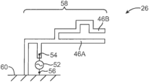
- FIG. 7 shows yet another illustrative configuration that may be used for the antenna elements of the antenna system 26 .
- antenna resonating element 58 has two main arms 46 A and 46 B.
- the arm 46 A is shorter than the arm 46 B and is therefore associated with higher frequencies of operation than the arm 46 A.
- the antenna resonating element 58 can be configured to cover a wider bandwidth or more than a single communications band of interest.
- the circuit structure may be particularly well suited for high frequency antennas and antenna arrays for use in base stations, repeaters (e.g., “femtocells”), relay stations, terminals, user devices, and/or other suitable components of 5G systems.
- 5G generally refers to high speed data communication over radio frequency signals. 5G networks and systems are capable of communicating data at much faster rates than previous generations of data communication standards (e.g., “4G, “LTE”).
- 5G frequencies can refer to frequencies that are 1.5 GHz or more, in some embodiments about 2.0 GHz or more, in some embodiments about 2.5 GHz or higher, in some embodiments about 3.0 GHz or higher, in some embodiments from about 3 GHz to about 300 GHz, or higher, in some embodiments from about 4 GHz to about 80 GHz, in some embodiments from about 5 GHz to about 80 GHz, in some embodiments from about 20 GHz to about 80 GHz, and in some embodiments from about 28 GHz to about 60 GHz.
- Various standards and specifications have been released quantifying the requirements of 5G communications. As one example, the International Telecommunications Union (ITU) released the International Mobile Telecommunications-2020 (“IMT-2020”) standard in 2015.
- the IMT-2020 standard specifies various data transmission criteria (e.g., downlink and uplink data rate, latency, etc.) for 5G.
- the IMT-2020 Standard defines uplink and downlink peak data rates as the minimum data rates for uploading and downloading data that a 5G system must support.
- the IMT-2020 standard sets the downlink peak data rate requirement as 20 Gbit/s and the uplink peak data rate as 10 Gbit/s.
- 3GPP 3 rd Generation Partnership Project
- 3GPP 3 rd Generation Partnership Project
- 3GPP 3 rd Generation Partnership Project
- 3GPP 3 rd Generation Partnership Project
- 3GPP published “Release 15” in 2018 defining “Phase 1” for standardization of 5G NR.
- 3GPP defines 5G frequency bands generally as “Frequency Range 1” (FR1) including sub-6 GHz frequencies and “Frequency Range 2” (FR2) as frequency bands ranging from 20-60 GHz.
- Antenna systems described herein can satisfy or qualify as “5G” under standards released by 3GPP, such as Release 15 (2016), and/or the IMT-2020 Standard.
- antenna elements and arrays may employ small feature sizes/spacing (e.g., fine pitch technology) that can improve antenna performance.
- the feature size spacing between antenna elements, width of antenna elements etc. is generally dependent on the wavelength (“ ⁇ ”) of the desired transmission and/or reception radio frequency propagating through the substrate dielectric on which the antenna element is formed (e.g., n ⁇ /4 where n is an integer).
- beamforming and/or beam steering can be employed to facilitate receiving and transmitting across multiple frequency ranges or channels (e.g., multiple-in-multiple-out (MIMO), massive MIMO).
- the high frequency 5G antenna elements can have a variety of configurations.
- the 5G antenna elements can be or include co-planar waveguide elements, patch arrays (e.g., mesh-grid patch arrays), other suitable 5G antenna configurations.
- the antenna elements can be configured to provide MIMO, massive MIMO functionality, beam steering, and the like.
- massive MIMO functionality generally refers to providing a large number transmission and receiving channels with an antenna array, for example 8 transmission (Tx) and 8 receive (Rx) channels (abbreviated as 8 ⁇ 8).
- Massive MIMO functionality may be provided with 8 ⁇ 8, 12 ⁇ 12, 16 ⁇ 16, 32 ⁇ 32, 64 ⁇ 64, or greater.
- the antenna elements can have a variety of configurations and arrangements and can be fabricated using a variety of manufacturing techniques.
- the antenna elements and/or associated elements e.g., ground elements, feed lines, etc.
- feature dimensions and/or spacing between antenna elements can be about 1,500 micrometers or less, in some embodiments 1,250 micrometers or less, in some embodiments 750 micrometers or less (e.g., center-to-center spacing of 1.5 mm or less), 650 micrometers or less, in some embodiments 550 micrometers or less, in some embodiments 450 micrometers or less, in some embodiments 350 micrometers or less, in some embodiments 250 micrometers or less, in some embodiments 150 micrometers or less, in some embodiments 100 micrometers or less, and in some embodiments 50 micrometers or less.
- feature sizes and/or spacings that are smaller and/or larger may be employed within the scope of this disclosure.
- an antenna array can have an average antenna element concentration of greater than 1,000 antenna elements per square centimeter, in some embodiments greater than 2,000 antenna elements per square centimeter, in some embodiments greater than 3,000 antenna elements per square centimeter, in some embodiments greater than 4,000 antenna elements per square centimeter, in some embodiments greater than 6,000 antenna elements per square centimeter, and in some embodiments greater than about 8,000 antenna elements per square centimeter.
- Such compact arrangement of antenna elements can provide a greater number of channels for MIMO functionality per unit area of the antenna area.
- the number of channels can correspond with (e.g., be equal to or proportional with) the number of antenna elements.
- a 5G antenna system 100 also includes a base station 102 , one or more relay stations 104 , one or more user computing devices 106 , one or more Wi-Fi repeaters 108 (e.g., “femtocells”), and/or other suitable antenna components for the 5G antenna system 100 .
- the relay stations 104 can be configured to facilitate communication with the base station 102 by the user computing devices 106 and/or other relay stations 104 by relaying or “repeating” signals between the base station 102 and the user computing devices 106 and/or relay stations 104 .
- the base station 102 can include a MIMO antenna array 110 configured to receive and/or transmit radio frequency signals 112 with the relay station(s) 104 , Wi-Fi repeaters 108 , and/or directly with the user computing device(s) 106 .
- the user computing device 106 is not necessarily limited by the present invention and include devices such as 5G smartphones.
- the MIMO antenna array 110 can employ beam steering to focus or direct radio frequency signals 112 with respect to the relay stations 104 .
- the MIMO antenna array 110 can be configured to adjust an elevation angle 114 with respect to an X-Y plane and/or a heading angle 116 defined in the Z-Y plane and with respect to the Z direction.
- one or more of the relay stations 104 , user computing devices 106 , Wi-Fi repeaters 108 can employ beam steering to improve reception and/or transmission ability with respect to MIMO antenna array 110 by directionally tuning sensitivity and/or power transmission of the device 104 , 106 , 108 with respect to the MIMO antenna array 110 of the base station 102 (e.g., by adjusting one or both of a relative elevation angle and/or relative azimuth angle of the respective devices).
- FIGS. 9 A and 9 B illustrate a top-down and side elevation view, respectively, of an example user computing device 106 .
- the user computing device 106 may include one or more antenna elements 200 , 202 (e.g., arranged as respective antenna arrays).
- the antenna elements 200 , 202 can be configured to perform beam steering in the X-Y plane (as illustrated by arrows 204 , 206 and corresponding with a relative azimuth angle).
- the antenna elements 200 , 202 can be configured to perform beam steering in the Z-Y plane (as illustrated by arrows 204 , 206 ).
- FIG. 10 depicts a simplified schematic view of a plurality of antenna arrays 302 connected using respective feed lines 304 (e.g., with a front end module).
- the antenna arrays 302 can be mounted to a side surface 306 of a substrate 308 , which may be formed from the polymer composition of the present invention.
- the antenna arrays 302 can include a plurality of vertically connected elements (e.g., as a mesh-grid array).
- the antenna array 302 can generally extend parallel with the side surface 306 of the substrate 308 .
- Shielding can optionally be provided on the side surface 306 of the substrate 308 such that the antenna arrays 302 are located outside of the shielding with respect to the substrate 308 .
- the vertical spacing distance between the vertically connected elements of the antenna array 302 can correspond with the “feature sizes” of the antenna arrays 302 . As such, in some embodiments, these spacing distances may be relatively small (e.g., less than about 750 micrometers) such that the antenna array 302 is a “fine pitch” antenna array 302 .
- FIG. 11 illustrates a side elevation view of a co-planar waveguide antenna 400 configuration.
- One or more co-planar ground layers 402 can be arranged parallel with an antenna element 404 (e.g., a patch antenna element).
- Another ground layer 406 may be spaced apart from the antenna element by a substrate 408 , which may be formed from the polymer composition of the present invention.
- One or more additional antenna elements 410 can be spaced apart from the antenna element 404 by a second layer or substrate 412 , which may also be formed from the polymer composition of the present invention.
- the dimensions “G” and “W” may correspond with “feature sizes” of the antenna 400 .
- the “G” dimension may correspond with a distance between the antenna element 404 and the co-planar ground layer(s) 406 .
- the “W” dimension can correspond with a width (e.g., linewidth) of the antenna element 404 .
- dimensions “G” and “W” may be relatively small (e.g., less than about 750 micrometers) such that the antenna 400 is a “fine pitch” antenna 400 .
- FIG. 12 A illustrates an antenna array 500 according to another aspect of the present disclosure.
- the antenna array 500 can include a substrate 510 , which may be formed from the polymer composition of the present invention, and a plurality of antenna elements 520 formed thereon.
- the plurality of antenna elements 520 can be approximately equally sized in the X- and/or Y-directions (e.g., square or rectangular).
- the plurality of antenna elements 520 can be spaced apart approximately equally in the X- and/or Y-directions.
- the dimensions of the antenna elements 520 and/or spacing therebetween can correspond with “feature sizes” of the antenna array 500 .
- the dimensions and/or spacing may be relatively small (e.g., less than about 750 micrometers) such that the antenna array 500 is a “fine pitch” antenna array 500 .
- the number of columns of antenna elements 520 illustrated in FIG. 12 is provided as an example only.
- the number of rows of antenna element 520 is provided as an example only.
- the tuned antenna array 500 can be used to provide massive MIMO functionality, for example in a base station (e.g., as described above with respect to FIG. 8 ). More specifically, radio frequency interactions between the various elements can be controlled or tuned to provide multiple transmitting and/or receiving channels. Transmitting power and/or receiving sensitivity can be directionally controlled to focus or direct radio frequency signals, for example as described with respect to the radio frequency signals 112 of FIG. 8 .
- the tuned antenna array 500 can provide a large number of antenna elements 522 in a small footprint. For example, the tuned antenna 500 can have an average antenna element concentration of 1,000 antenna elements per square cm or greater. Such compact arrangement of antenna elements can provide a greater number of channels for MIMO functionality per unit area. For example, the number of channels can correspond with (e.g., be equal to or proportional with) the number of antenna elements.
- FIG. 12 B illustrates an antenna array 540 formed with laser direct structuring, which may optionally be employed to form the antenna elements.
- the antenna array 540 can include a plurality of antenna elements 542 and plurality of feed lines 544 connecting the antenna elements 542 (e.g., with other antenna elements 542 , a front end module, or other suitable component).
- the antenna elements 542 can have respective widths “w” and spacing distances “S 1 ” and “S 2 ” therebetween (e.g., in the X-direction and Y-direction, respectively). These dimensions can be selected to achieve 5G radio frequency communication at a desired 5G frequency.
- the dimensions can be selected to tune the antenna array 540 for transmission and/or reception of data using radio frequency signals that are within the 5G frequency spectrum.
- the dimensions can be selected based on the material properties of the substrate. For example, one or more of “w”, “S 1 ,” or “S 2 ” can correspond with a multiple of a propagation wavelength (“ ⁇ ”) of the desired frequency through the substrate material (e.g., n ⁇ /4 where n is an integer).
- A can be calculated as follows:
- ⁇ c f ⁇ ⁇ R
- c the speed of light in a vacuum
- ⁇ R the dielectric constant of the substrate (or surrounding material)
- f the desired frequency
- FIG. 12 C illustrates an example antenna configuration 560 according to aspects of the present disclosure.
- the antenna configuration 560 can include multiple antenna elements 562 arranged in parallel long edges of a substrate 564 , which may be formed from the polymer composition of the present invention.
- the various antenna elements 562 can have respective lengths, “L” (and spacing distances therebetween) that tune the antenna configuration 560 for reception and/or transmission at a desired frequency and/or frequency range. More specifically, such dimensions can be selected based on a propagation wavelength, ⁇ , at the desired frequency for the substrate material, for example as described above with reference to FIG. 12 B .
- FIGS. 13 A through 13 C depict simplified sequential diagrams of a laser direct structuring manufacturing process that can be used to form antenna elements and/or arrays according to aspects of the present disclosure.
- a substrate 600 can be formed from the polymer composition of the present invention using any desired technique (e.g., injection molding).
- a laser 602 can be used to activate the laser activatable additive to form a circuit pattern 604 that can include one or more of the antenna elements and/or arrays.
- the laser can melt conductive particles in the polymer composition to form the circuit pattern 604 .
- the substrate 600 can be submerged in an electroless copper bath to plate the circuit pattern 604 and form the antenna elements, elements arrays, other components, and/or conductive lines therebetween.
- the melt viscosity may be determined in accordance with ISO Test No. 11443:2014 at a shear rate of 400 s ⁇ 1 and temperature 15° C. above the melting temperature (e.g., about 350° C.) using a Dynisco LCR7001 capillary rheometer.
- the rheometer orifice (die) had a diameter of 1 mm, length of 20 mm, L/D ratio of 20.1, and an entrance angle of 180°.
- the diameter of the barrel was 9.55 mm+0.005 mm and the length of the rod was 233.4 mm.
- the melting temperature may be determined by differential scanning calorimetry (“DSC”) as is known in the art.
- the melting temperature is the differential scanning calorimetry (DSC) peak melt temperature as determined by ISO Test No. 11357-3:2018. Under the DSC procedure, samples were heated and cooled at 20° C. per minute as stated in ISO Standard 10350 using DSC measurements conducted on a TA Q2000 Instrument.
- the deflection temperature under load may be determined in accordance with ISO Test No. 75-2:2013 (technically equivalent to ASTM D648). More particularly, a test strip sample having a length of 80 mm, thickness of 10 mm, and width of 4 mm may be subjected to an edgewise three-point bending test in which the specified load (maximum outer fibers stress) was 1.8 Megapascals. The specimen may be lowered into a silicone oil bath where the temperature is raised at 2° C. per minute until it deflects 0.25 mm (0.32 mm for ISO Test No. 75-2:2013).
- Tensile Modulus, Tensile Stress, and Tensile Elongation Tensile properties may be tested according to ISO Test No. 527:2019 (technically equivalent to ASTM D638). Modulus and strength measurements may be made on the same test strip sample having a length of 80 mm, thickness of 10 mm, and width of 4 mm. The testing temperature may be 23° C., and the testing speeds may be 1 or 5 mm/min.
- Flexural Modulus, Flexural Stress, and Flexural Elongation Flexural properties may be tested according to ISO Test No. 178:2019 (technically equivalent to ASTM D790). This test may be performed on a 64 mm support span. Tests may be run on the center portions of uncut ISO 3167 multi-purpose bars. The testing temperature may be 23° C. and the testing speed may be 2 mm/min.
- Charpy Impact Strength Charpy properties may be tested according to ISO Test No. ISO 179-1:2010) (technically equivalent to ASTM D256-10, Method B). This test may be run using a Type 1 specimen size (length of 80 mm, width of 10 mm, and thickness of 4 mm). When testing the notched impact strength, the notch may be a Type A notch (0.25 mm base radius). Specimens may be cut from the center of a multi-purpose bar using a single tooth milling machine. The testing temperature may be 23° C.
- Dielectric Constant (“Dk”) and Dissipation Factor (“Df”): The dielectric constant (or relative static permittivity) and dissipation factor are determined using a known split-post dielectric resonator technique, such as described in Baker-Jarvis, et al., IEEE Trans. on Dielectric and Electrical Insulation, 5(4), p. 571 (1998) and Krupka, et al., Proc. 7 th International Conference on Dielectric Materials: Measurements and Applications, IEEE Conference Publication No. 430 (September 1996). More particularly, a plaque sample having a size of 80 mm ⁇ 90 mm ⁇ 3 mm was inserted between two fixed dielectric resonators. The resonator measured the permittivity component in the plane of the specimen. Five (5) samples are tested and the average value is recorded. The split-post resonator can be used to make dielectric measurements in the low gigahertz region, such as 1 GHz from 2 GHz.
- Heat Cycle Test Specimens are placed in a temperature control chamber and heated/cooled within a temperature range of from ⁇ 30° C. and 100° C. Initially, the samples are heated until reaching a temperature of 100° C., when they were immediately cooled. When the temperature reaches ⁇ 30° C., the specimens are immediately heated again until reaching 100° C. Twenty three (23) heating/cooling cycles may be performed over a 3-hour time period.
- the surface and volume resistivity values may be determined in accordance with IEC 62631-3-1:2016 or ASTM D257-14. According to this procedure, a standard specimen (e.g., 1 meter cube) is placed between two electrodes. A voltage is applied for sixty (60) seconds and the resistance is measured. The surface resistivity is the quotient of the potential gradient (in V/m) and the current per unit of electrode length (in A/m), and generally represents the resistance to leakage current along the surface of an insulating material.
- volume resistivity is also determined as the ratio of the potential gradient parallel to the current in a material to the current density. In SI units, volume resistivity is numerically equal to the direct-current resistance between opposite faces of a one-meter cube of the material (ohm-m or ohm-cm).
- Samples 1-4 are formed from various percentages of a liquid crystalline polymer (“LCP 1” and “LCP 2”), wollastonite fibers (NyglosTM 8), carbon black pigment, carbon fibers, and a lubricant (GlycolubeTM P).
- LCP 1 is formed from 60 mol. % HBA, 5 mol. % HNA, 12 mol. % BP, 17.5 mol. % TA, and 5 mol. % APAP.
- LCP 2 is formed from 73 mol. % HBA and 27 mol. % HNA. Compounding was performed using an 18-mm single screw extruder. The samples are injection molded into plaques (60 mm ⁇ 60 mm).
- Samples 3-4 were also subjected to a heat cycle test as described above. Upon testing, it was determined that the resulting dissipation factor for the samples was 0.021 and 0.015, respectively. Thus, the ratio of the dissipation factor after heat cycle testing to the initial dissipation factor for Samples 3 and 4 was 1.24 and 0.86, respectively. Upon testing, it was also determined that the resulting dielectric constant for the samples was 12.9 and 12.6, respectively. Thus, the ratio of the dielectric constant after heat cycle testing to the initial dielectric constant for Samples 3 and 4 was 0.98 and 1.01, respectively.
- Samples 5-9 are formed from various percentages of a liquid crystalline polymer (“LCP 1” and “LCP 2”), NyglosTM 8, carbon black pigment, graphite, and GlycolubeTM P. Compounding was performed using an 18-mm single screw extruder. The samples are injection molded into plaques (60 mm ⁇ 60 mm).
- Samples 5-7 were also subjected to a heat cycle test as described above. Upon testing, it was determined that the resulting dissipation factor for the samples was 0.0578, 0.0214, and 0.0098, respectively. Thus, the ratio of the dissipation factor after heat cycle testing to the initial dissipation factor for Samples 5, 6, and 7 was 1.17, 1.06, and 1.09, respectively. Upon testing, it was also determined that the resulting dielectric constant for the samples was 12.6, 8.9, and 6.3, respectively. Thus, the ratio of the dielectric constant after heat cycle testing to the initial dielectric constant for Samples 5, 6, and 7 was 1.0, 1.0, and, 1.0, respectively.
Abstract
A circuit structure that comprises a substrate and one or more conductive elements disposed on the substrate is provided. The substrate comprises a polymer composition that comprises an electrically conductive filler distributed within a polymer matrix. The polymer matrix contains at least one thermoplastic high performance polymer having a deflection temperature under load of about 40° C. or more as determined in accordance with ISO 75-2:2013 at a load of 1.8 MPa, and the polymer composition exhibits a dielectric constant of about 4 or more and a dissipation factor of about 0.3 or less, as determined at a frequency of 2 GHz.
Description
The present application claims filing benefit of United States Provisional Patent Application Serial Nos. 62/981,667 (filing date of Feb. 26, 2020), 62/981,681 (filing date of Feb. 26, 2020), 63/057,345 (filing date of Jul. 28, 2020), and 63/057,349 (filing date of Jul. 28, 2020), which are incorporated herein by reference in their entirety.
Molded interconnect devices (“MIDs”) are three-dimensional electromechanical parts that typically include plastic components and electronic circuit traces. A plastic substrate is created and electrical circuits and devices are plated, layered or implanted upon the plastic substrate. MIDs typically have fewer parts than conventionally produced devices, which results in space and weight savings. Current processes for manufacturing MIDs include two-shot molding and laser direct structuring. Laser direct structuring, for instance, involves the use of spinel crystals (e.g., copper chromite) that act as a seed for initiating metallization of the substrate. After the metal layer is formed, a laser etches a wiring pattern onto the part and prepares it for metallization. Despite its benefits, one of the limitations of laser direct structured materials is that the spinel crystals tend to adversely impact the performance of the composition at the high frequencies often encountered in antenna systems. As such, a need currently exists for an improved polymer substrate that can be plated and yet retain good performance at high frequency ranges.
In accordance with one embodiment of the present invention, a circuit structure is disclosed that comprises a substrate and one or more conductive elements disposed on the substrate. The substrate comprises a polymer composition that comprises an electrically conductive filler distributed within a polymer matrix. The polymer matrix contains at least one thermoplastic high performance polymer having a deflection under load of about 40° C. or more as determined in accordance with ISO 75-2:2013 at a load of 1.8 MPa, and the polymer composition exhibits a dielectric constant of about 4 or more and a dissipation factor of about 0.3 or less, as determined at a frequency of 2 GHz.
Other features and aspects of the present invention are set forth in greater detail below.
A full and enabling disclosure of the present invention, including the best mode thereof to one skilled in the art, is set forth more particularly in the remainder of the specification, including reference to the accompanying figures, in which:
It is to be understood by one of ordinary skill in the art that the present discussion is a description of exemplary embodiments only, and is not intended as limiting the broader aspects of the present invention.
Generally speaking, the present invention is directed to a circuit structure that contains a substrate and one or more conductive elements disposed thereon. The substrate contains a polymer composition that includes an electrically conductive filler, which is distributed within a polymer matrix that includes a high performance thermoplastic polymer. By selectively controlling various aspects of the composition, the present inventor has discovered that the resulting composition is able to maintain a unique combination of a high dielectric constant and low dissipation factor for use in various types of electronic components, such as an antenna system. For example, the polymer composition may exhibit a high dielectric constant of about 4 or more, in some embodiments about 5 or more, in some embodiments about 6 or more, in some embodiments from about 8 to about 30, in some embodiments from about 10 to about 25, and in some embodiments, from about 12 to about 24, as determined by the split post resonator method at a frequency of 2 GHz. Such a high dielectric constant can facilitate the ability to form a thin substrate and also allow multiple conductive elements (e.g., antennae) to be employed that operate simultaneously with only a minimal level of electrical interference. The dissipation factor, a measure of the loss rate of energy, may also be relatively low, such as about 0.3 or less, in some embodiments about 0.2 or less, in some embodiments about 0.1 or less, in some embodiments about 0.06 or less, in some embodiments about 0.04 or less, and in some embodiments, from about 0.001 to about 0.03, as determined by the split post resonator method at a frequency of 2 GHz. The present inventor has also discovered that the dielectric constant and dissipation factor can be maintained within the ranges noted above even when exposed to various temperatures, such as a temperature of from about −30° C. to about 100° C. For example, when subjected to a heat cycle test as described herein, the ratio of the dielectric constant after heat cycling to the initial dielectric constant may be about 0.8 or more, in some embodiments about 0.9 or more, and in some embodiments, from about 0.95 to about 1.1. Likewise, the ratio of the dissipation factor after being exposed to the high temperature to the initial dissipation factor may be about 1.3 or less, in some embodiments about 1.2 or less, in some embodiments about 1.1 or less, in some embodiments about 1.0 or less, in some embodiments about 0.95 or less, in some embodiments from about 0.1 to about 0.95, and in some embodiments, from about 0.2 to about 0.9. The change in dissipation factor (i.e., the initial dissipation factor—the dissipation factor after heat cycling) may also range from about −0.1 to about 0.1, in some embodiments from about −0.05 to about 0.01, and in some embodiments, from about −0.001 to 0.
Conventionally, it was believed that polymer compositions that possess the combination of a high dielectric constant and low dissipation factor would not also possess a high enough electrical conductivity to allow for metallization of the substrate. The present inventor has discovered, however, that the polymer composition may exhibit a controlled resistivity that allows it to remain generally antistatic in nature such that a substantial amount of electrical current does not flow through the part, but nevertheless exhibits a sufficient degree of electrostatic dissipation to facilitate plating and formation of conductive traces thereon. The surface resistivity may, for instance, range from about 1×10¹² ohms to about 1×10¹⁸ ohms, in some embodiments from about 1×10¹³ ohms to about 1×10¹⁸ ohms, in some embodiments from about 1×10¹⁴ ohms to about 1×10¹⁷ ohms, and in some embodiments, from about 1×10¹⁵ ohms to about 1×10¹⁷ ohms, such as determined in accordance with ASTM D257-14 (technically equivalent to IEC 62631-3-1). Likewise, the composition may also exhibit a volume resistivity of from about 1×10¹⁰ ohm-m to about 1×10¹⁶ ohm-m, in some embodiments from about 1×10¹¹ ohm-m to about 1×10¹⁶ ohm-m, in some embodiments from about 1×10¹² ohm-m to about 1×10¹⁵ ohm-m, and in some embodiments, from about 1×10¹³ ohm-m to about 1×10¹⁵ ohm-m, such as determined at a temperature of about 20° C. in accordance with ASTM D257-14 (technically equivalent to IEC 62631-3-1).
The polymer composition of the present invention may also possess excellent strength properties. For example, the composition may exhibit a Charpy unnotched and/or notched impact strength of about 2 kJ/m2, in some embodiments from about 4 to about 40 kJ/m2, and in some embodiments, from about 6 to about 30 kJ/m2, measured at 23° C. according to ISO Test No. 179-1:2010. The composition may also exhibit a tensile strength of from about 20 to about 500 MPa, in some embodiments from about 50 to about 400 MPa, and in some embodiments, from about 60 to about 350 MPa; tensile break strain of about 0.5% or more, in some embodiments from about 0.8% to about 15%, and in some embodiments, from about 1% to about 10%; and/or tensile modulus of from about 5,000 MPa to about 30,000 MPa, in some embodiments from about 7,000 MPa to about 25,000 MPa, and in some embodiments, from about 10,000 MPa to about 20,000 MPa. The tensile properties may be determined in accordance with ISO Test No. 527:2019 at 23° C. The composition may also exhibit a flexural strength of from about 40 to about 500 MPa, in some embodiments from about 50 to about 400 MPa, and in some embodiments, from about 100 to about 350 MPa; flexural break strain of about 0.5% or more, in some embodiments from about 0.8% to about 15%, and in some embodiments, from about 1% to about 10%; and/or flexural modulus of about 7,000 MPa or more, in some embodiments from about 9,000 MPa or more, in some embodiments, from about 10,000 MPa to about 30,000 MPa, and in some embodiments, from about 12,000 MPa to about 25,000 MPa. The flexural properties may be determined in accordance with ISO Test No. 178:2019 at 23° C.
As indicated above, one benefit of the present invention is that a substrate formed from the polymer composition can be readily plated without the use of conventional laser activatable spinel crystals, which generally have the formula, AB2O4, wherein A is a metal cation having a valance of 2 (e.g., cadmium, chromium, manganese, nickel, zinc, copper, cobalt, iron, magnesium, tin, or titanium) and B is a metal cation having a valance of 3 (e.g., chromium, iron, aluminum, nickel, manganese, or tin). Typically, A in the formula above provides the primary cation component of a first metal oxide cluster and B provides the primary cation component of a second metal oxide cluster. For example, the first metal oxide cluster generally has a tetrahedral structure and the second metal oxide cluster generally has an octahedral cluster. Particular examples of such spinel crystals include, for instance, MgAl2O4, ZnAl2O4, FeAl2O4, CuFe2O4, CuCr2O4, MnFe2O4, NiFe2O4, TiFe2O4, FeCr2O4, or MgCr2O4. The polymer composition may be free of such spinel crystals (i.e., 0 wt. %), or such crystals may be present in only a small concentration, such as in an amount of about 1 wt. % or less, in some embodiments about 0.5 wt. % or less, and in some embodiments, from about 0.001 wt. % to about 0.2 wt. %.
Various embodiments of the present invention will now be described in more detail.
I. Polymer Composition
A. Polymer Matrix
The polymer matrix generally contains one or more thermoplastic high performance polymers, generally in an amount of from about 30 wt. % to about 80 wt. %, in some embodiments from about 40 wt. % to about 75 wt. %, and in some embodiments, from about 50 wt. % to about 70 wt. % of the entire polymer composition. The high performance polymers may have a high degree of heat resistance, such as reflected by a deflection temperature under load (“DTUL”) of about 40° C. or more, in some embodiments about 50° C. or more, in some embodiments about 60° C. or more, in some embodiments from about from about 100° C. to about 320° C., in some embodiments from about 150° C. to about 310° C., and in some embodiments, from about 220° C. to about 300° C., as determined in accordance with ISO 75-2:2013 at a load of 1.8 MPa. In addition to exhibiting a high degree of heat resistance, the polymers also typically have a high glass transition temperature, such as about 40° C. or more, in some embodiments about 50° C. or more, in some embodiments about 60° C. or more, in some embodiments about 70° C. or more, in some embodiments about 80° C. or more, and in some embodiments, from about 100° C. to about 320° C. When semi-crystalline or crystalline polymers are employed, the high performance polymers may also have a high melting temperature, such as about 140° C. or more, in some embodiments from about 150° C. to about 420° C., and in some embodiments, in some embodiments from about 200° C. to about 410° C., and in some embodiments, from about 300° C. to about 400° C. The glass transition and melting temperatures may be determined as is well known in the art using differential scanning calorimetry (“DSC”), such as determined by ISO 11357-2:2020 (glass transition) and 11357-3:2018 (melting).
Suitable high performance, thermoplastic polymers for this purpose may include, for instance, polyamides (e.g., aliphatic, semi-aromatic, or aromatic polyamides), polyesters, polyarylene sulfides, liquid crystalline polymers (e.g., wholly aromatic polyesters, polyesteramides, etc.), polycarbonates, polyphenylene ethers, polyphenylene oxides, polyimides (e.g., polyetherimide), etc., as well as blends thereof. The exact choice of the polymer system will depend upon a variety of factors, such as the nature of other fillers included within the composition, the manner in which the composition is formed and/or processed, and the specific requirements of the intended application.
Aromatic polymers, for instance, are particularly suitable for use in the polymer matrix. The aromatic polymers can be substantially amorphous, semi-crystalline, or crystalline in nature. One example of a suitable semi-crystalline aromatic polymer, for instance, is an aromatic polyester, which may be a condensation product of at least one diol (e.g., aliphatic and/or cycloaliphatic) with at least one aromatic dicarboxylic acid, such as those having from 4 to 20 carbon atoms, and in some embodiments, from 8 to 14 carbon atoms. Suitable diols may include, for instance, neopentyl glycol, cyclohexanedimethanol, 2,2-dimethyl-1,3-propane diol and aliphatic glycols of the formula HO(CH2)nOH where n is an integer of 2 to 10. Suitable aromatic dicarboxylic acids may include, for instance, isophthalic acid, terephthalic acid, 1,2-di(p-carboxyphenyl)ethane, 4,4′-dicarboxydiphenyl ether, etc., as well as combinations thereof. Fused rings can also be present such as in 1,4- or 1,5- or 2,6-naphthalene-dicarboxylic acids. Particular examples of such aromatic polyesters may include, for instance, poly(ethylene terephthalate) (PET), poly(1,4-butylene terephthalate) (PBT), poly(1,3-propylene terephthalate) (PPT), poly(1,4-butylene 2,6-naphthalate) (PBN), poly(ethylene 2,6-naphthalate) (PEN), poly(1,4-cyclohexylene dimethylene terephthalate) (PCT), as well as mixtures of the foregoing.
Derivatives and/or copolymers of aromatic polyesters (e.g., polyethylene terephthalate) may also be employed. For instance, in one embodiment, a modifying acid and/or diol may be used to form a derivative of such polymers. As used herein, the terms “modifying acid” and “modifying diol” are meant to define compounds that can form part of the acid and diol repeat units of a polyester, respectively, and which can modify a polyester to reduce its crystallinity or render the polyester amorphous. Examples of modifying acid components may include, but are not limited to, isophthalic acid, phthalic acid, 1,3-cyclohexanedicarboxylic acid, 1,4-cyclohexane dicarboxylic acid, 2,6-naphthaline dicarboxylic acid, succinic acid, glutaric acid, adipic acid, sebacic acid, suberic acid, 1,12-dodecanedioic acid, etc. In practice, it is often preferable to use a functional acid derivative thereof such as the dimethyl, diethyl, or dipropyl ester of the dicarboxylic acid. The anhydrides or acid halides of these acids also may be employed where practical. Examples of modifying diol components may include, but are not limited to, neopentyl glycol, 1,4-cyclohexanedimethanol, 1,2-propanediol, 1,3-propanediol, 2-methy-1,3-propanediol, 1,4-butanediol, 1,6-hexanediol, 1,2-cyclohexanediol, 1,4-cyclohexanediol, 1,2-cyclohexanedimethanol, 1,3-cyclohexanedimethanol, 2,2,4,4-tetramethyl 1,3-cyclobutane diol, Z,8-bis(hydroxymethyltricyclo-[5.2.1.0]-decane wherein Z represents 3, 4, or 5; 1,4-bis(2-hydroxyethoxy)benzene, 4,4′-bis(2-hydroxyethoxy) diphenylether [bis-hydroxyethyl bisphenol A], 4,4′-Bis(2-hydroxyethoxy)diphenylsulfide [bis-hydroxyethyl bisphenol S] and diols containing one or more oxygen atoms in the chain, e.g. diethylene glycol, triethylene glycol, dipropylene glycol, tripropylene glycol, etc. In general, these diols contain 2 to 18, and in some embodiments, 2 to 8 carbon atoms. Cycloaliphatic diols can be employed in their cis- or trans-configuration or as mixtures of both forms.
The aromatic polyesters, such as described above, typically have a DTUL value of from about 40° C. to about 80° C., in some embodiments from about 45° C. to about 75° C., and in some embodiments, from about 50° C. to about 70° C. as determined in accordance with ISO 75-2:2013 at a load of 1.8 MPa. The aromatic polyesters likewise typically have a glass transition temperature of from about 30° C. to about 120° C., in some embodiments from about 40° C. to about 110° C., and in some embodiments, from about 50° C. to about 100° C., such as determined by ISO 11357-2:2020, as well as a melting temperature of from about 170° C. to about 300° C., in some embodiments from about 190° C. to about 280° C., and in some embodiments, from about 210° C. to about 260° C., such as determined in accordance with ISO 11357-2:2018. The aromatic polyesters may also have an intrinsic viscosity of from about 0.1 dl/g to about 6 dl/g, in some embodiments from about 0.2 to about 5 dl/g, and in some embodiments from about 0.3 to about 1 dl/g, such as determined in accordance with ISO 1628-5:1998.
Polyarylene sulfides are also suitable semi-crystalline aromatic polymers. The polyarylene sulfide may be homopolymers or copolymers. For instance, selective combination of dihaloaromatic compounds can result in a polyarylene sulfide copolymer containing not less than two different units. For instance, when p-dichlorobenzene is used in combination with m-dichlorobenzene or 4,4′-dichlorodiphenylsulfone, a polyarylene sulfide copolymer can be formed containing segments having the structure of formula:
and segments having the structure of formula:

or segments having the structure of formula:
The polyarylene sulfide may be linear, semi-linear, branched or crosslinked. Linear polyarylene sulfides typically contain 80 mol % or more of the repeating unit —(Ar—S)—. Such linear polymers may also include a small amount of a branching unit or a cross-linking unit, but the amount of branching or cross-linking units is typically less than about 1 mol % of the total monomer units of the polyarylene sulfide. A linear polyarylene sulfide polymer may be a random copolymer or a block copolymer containing the above-mentioned repeating unit. Semi-linear polyarylene sulfides may likewise have a cross-linking structure or a branched structure introduced into the polymer a small amount of one or more monomers having three or more reactive functional groups. By way of example, monomer components used in forming a semi-linear polyarylene sulfide can include an amount of polyhaloaromatic compounds having two or more halogen substituents per molecule which can be utilized in preparing branched polymers. Such monomers can be represented by the formula R′Xn, where each X is selected from chlorine, bromine, and iodine, n is an integer of 3 to 6, and R′ is a polyvalent aromatic radical of valence n which can have up to about 4 methyl substituents, the total number of carbon atoms in R′ being within the range of 6 to about 16. Examples of some polyhaloaromatic compounds having more than two halogens substituted per molecule that can be employed in forming a semi-linear polyarylene sulfide include 1,2,3-trichlorobenzene, 1,2,4-trichlorobenzene, 1,3-dichloro-5-bromobenzene, 1,2,4-triiodobenzene, 1,2,3,5-tetrabromobenzene, hexachlorobenzene, 1,3,5-trichloro-2,4,6-trimethylbenzene, 2,2′,4,4′-tetrachlorobiphenyl, 2,2′,5,5′-tetra-iodobiphenyl, 2,2′,6,6′-tetrabromo-3,3′,5,5′-tetramethylbiphenyl, 1,2,3,4-tetrachloronaphthalene, 1,2,4-tribromo-6-methylnaphthalene, etc., and mixtures thereof.
The polyarylene sulfides, such as described above, typically have a DTUL value of from about 70° C. to about 220° C., in some embodiments from about 90° C. to about 200° C., and in some embodiments, from about 120° C. to about 180° C. as determined in accordance with ISO 75-2:2013 at a load of 1.8 MPa. The polyarylene sulfides likewise typically have a glass transition temperature of from about 50° C. to about 120° C., in some embodiments from about 60° C. to about 115° C., and in some embodiments, from about 70° C. to about 110° C., such as determined by ISO 11357-2:2020, as well as a melting temperature of from about 220° C. to about 340° C., in some embodiments from about 240° C. to about 320° C., and in some embodiments, from about 260° C. to about 300° C., such as determined in accordance with ISO 11357-3:2018.
As indicated above, substantially amorphous polymers may also be employed that lack a distinct melting point temperature. Suitable amorphous polymers may include, for instance, aromatic polycarbonates, which typically contains repeating structural carbonate units of the formula —R1—O—C(O)—O—. The polycarbonate is aromatic in that at least a portion (e.g., 60% or more) of the total number of R1 groups contain aromatic moieties and the balance thereof are aliphatic, alicyclic, or aromatic. In one embodiment, for instance, R1 may a C6-30 aromatic group, that is, contains at least one aromatic moiety. Typically, R1 is derived from a dihydroxy aromatic compound of the general formula HO—R1—OH, such as those having the specific formula referenced below:
HO-A1-Y1-A2-OH
wherein,
HO-A1-Y1-A2-OH
wherein,
A1 and A2 are independently a monocyclic divalent aromatic group; and
Y1 is a single bond or a bridging group having one or more atoms that separate A1 from A2. In one particular embodiment, the dihydroxy aromatic compound may be derived from the following formula (I):

wherein,
Ra and Rb are each independently a halogen or C1-12 alkyl group, such as a C1-3 alkyl group (e.g., methyl) disposed meta to the hydroxy group on each arylene group;
p and q are each independently 0 to 4 (e.g., 1); and
Xa represents a bridging group connecting the two hydroxy-substituted aromatic groups, where the bridging group and the hydroxy substituent of each C6 arylene group are disposed ortho, meta, or para (specifically para) to each other on the C6 arylene group.
In one embodiment, Xa may be a substituted or unsubstituted C3-18 cycloalkylidene, a C1-25 alkylidene of formula —C(Rc)(Rd)— wherein Rc and Rd are each independently hydrogen, C1-12 alkyl, C1-12 cycloalkyl, C7-12 arylalcyl, C7-12 heteroalkyl, or cyclic C7-12 heteroarylalkyl, or a group of the formula —C(═Re)— wherein Re is a divalent C1-12 hydrocarbon group. Exemplary groups of this type include methylene, cyclohexylmethylene, ethylidene, neopentylidene, and isopropylidene, as well as 2-[2.2.1]-bicycloheptylidene, cyclohexylidene, cyclopentylidene, cyclododecylidene, and adamantylidene. A specific example wherein Xa is a substituted cycloalkylidene is the cyclohexylidene-bridged, alkyl-substituted bisphenol of the following formula (II):

wherein,
Ra′ and Rb′ are each independently C1-12 alkyl (e.g., C1-4 alkyl, such as methyl), and may optionally be disposed meta to the cyclohexylidene bridging group;
Rg is C1-12 alkyl (e.g., C1-4 alkyl) or halogen;
r and s are each independently 1 to 4 (e.g., 1); and
t is 0 to 10, such as 0 to 5.
The cyclohexylidene-bridged bisphenol can be the reaction product of two moles of o-cresol with one mole of cyclohexanone. In another embodiment, the cyclohexylidene-bridged bisphenol can be the reaction product of two moles of a cresol with one mole of a hydrogenated isophorone (e.g., 1,1,3-trimethyl-3-cyclohexane-5-one). Such cyclohexane-containing bisphenols, for example the reaction product of two moles of a phenol with one mole of a hydrogenated isophorone, are useful for making polycarbonate polymers with high glass transition temperatures and high heat distortion temperatures.
In another embodiment, Xa may be a C1-18 alkylene group, a C3-18 cycloalkylene group, a fused C6-18 cycloalkylene group, or a group of the formula —B1—W—B2—, wherein B1 and B2 are independently a C1-6 alkylene group and W is a C3-12 cycloalkylidene group or a C6-16 arylene group.
Xa may also be a substituted C3-18 cycloalkylidene of the following formula (III):

wherein,
Rr, Rp, Rq, and Rt are each independently hydrogen, halogen, oxygen, or C1-12 organic groups;
l is a direct bond, a carbon, or a divalent oxygen, sulfur, or —N(Z)—, wherein Z is hydrogen, halogen, hydroxy, C1-12 alkyl, C1-12 alkoxy, or C1-12 acyl;
h is 0 to 2;
j is 1 or 2;
i is 0 or 1; and
k is 0 to 3, with the proviso that at least two of Rr, Rp, Rq, and Rt taken together are a fused cycloaliphatic, aromatic, or heteroaromatic ring.
Other useful aromatic dihydroxy aromatic compounds include those having the following formula (IV):

wherein,
Rh is independently a halogen atom (e.g., bromine), C1-10 hydrocarbyl (e.g., C1-10 alkyl group), a halogen-substituted C1-10 alkyl group, a C6-10 aryl group, or a halogen-substituted C6-10 aryl group;
n is 0 to 4.
Specific examples of bisphenol compounds of formula (I) include, for instance, 1,1-bis(4-hydroxyphenyl) methane, 1,1-bis(4-hydroxyphenyl) ethane, 2,2-bis(4-hydroxyphenyl)propane (hereinafter “bisphenol A” or “BPA”), 2,2-bis(4-hydroxyphenyl)butane, 2,2-bis(4-hydroxyphenyl)octane, 1,1-bis(4-hydroxyphenyl)propane, 1,1-bis(4-hydroxyphenyl) n-butane, 2,2-bis(4-hydroxy-1-methylphenyl)propane, 1,1-bis(4-hydroxy-t-butylphenyl)propane, 3,3-bis(4-hydroxyphenyl)phthalimidine, 2-phenyl-3,3-bis(4-hydroxyphenyl)phthalimidine (PPPBP), and 1,1-bis(4-hydroxy-3-methylphenyl)cyclohexane (DMBPC). In one specific embodiment, the polycarbonate may be a linear homopolymer derived from bisphenol A, in which each of A1 and A2 is p-phenylene and Y1 is isopropylidene in formula (I).
Other examples of suitable aromatic dihydroxy compounds may include, but not limited to, 4,4′-dihydroxybiphenyl, 1,6-dihydroxynaphthalene, 2,6-dihydroxynaphthalene, bis(4-hydroxyphenyl)methane, bis(4-hydroxyphenyl)diphenylmethane, bis(4-hydroxyphenyl)-1-naphthylmethane, 1,2-bis(4-hydroxyphenyl)ethane, 1,1-bis(4-hydroxyphenyl)-1-phenylethane, 2-(4-hydroxyphenyl)-2-(3-hydroxyphenyl)propane, bis(4-hydroxyphenyl)phenylmethane, 2,2-bis(4-hydroxy-3-bromophenyl)propane, 1,1-bis(hydroxyphenyl)cyclopentane, 1,1-bis(4-hydroxyphenyl)cyclohexane, 1,1-bis(4-hydroxyphenyl)isobutene, 1,1-bis(4-hydroxyphenyl)cyclododecane, trans-2,3-bis(4-hydroxyphenyl)-2-butene, 2,2-bis(4-hydroxyphenyl)adamantane, alpha, alpha′-bis(4-hydroxyphenyl)toluene, bis(4-hydroxyphenyl)acetonitrile, 2,2-bis(3-methyl-4-hydroxyphenyl)propane, 2,2-bis(3-ethyl-4-hydroxyphenyl)propane, 2,2-bis(3-n-propyl-4-hydroxyphenyl)propane, 2,2-bis(3-isopropyl-4-hydroxyphenyl)propane, 2,2-bis(3-sec-butyl-4-hydroxyphenyl)propane, 2,2-bis(3-t-butyl-4-hydroxyphenyl)propane, 2,2-bis(3-cyclohexyl-4-hydroxyphenyl)propane, 2,2-bis(3-allyl-4-hydroxyphenyl)propane, 2,2-bis(3-methoxy-4-hydroxyphenyl)propane, 2,2-bis(4-hydroxyphenyl)hexafluoropropane, 1,1-dichloro-2,2-bis(4-hydroxyphenyl)ethylene, 1,1-dibromo-2,2-bis(4-hydroxyphenyl)ethylene, 1,1-dichloro-2,2-bis(5-phenoxy-4-hydroxyphenyl)ethylene 4,4′-dihydroxybenzophenone, 3,3-bis(4-hydroxyphenyl)-2-butanone, 1,6-bis(4-hydroxyphenyl)-1,6-hexanedione, ethylene glycol bis(4-hydroxyphenyl)ether, bis(4-hydroxyphenyl)ether, bis(4-hydroxyphenyl)sulfide, bis(4-hydroxyphenyl)sulfoxide, bis(4-hydroxyphenyl)sulfone, 9,9-bis(4-hydroxyphenyl)fluorine, 2,7-dihydroxypyrene, 6,6′-dihydroxy-3,3,3′,3′-tetramethylspiro(bis)indane (“spirobiindane bisphenol”), 3,3-bis(4-hydroxyphenyl)phthalimide, 2,6-dihydroxydibenzo-p-dioxin, 2,6-dihydroxythianthrene, 2,7-dihydroxyphenoxathin, 2,7-dihydroxy-9,10-dimethylphenazine, 3,6-dihydroxydibenzofuran, 3,6-dihydroxydibenzothiophene, and 2,7-dihydroxycarbazole, resorcinol, substituted resorcinol compounds such as 5-methyl resorcinol, 5-ethyl resorcinol, 5-propyl resorcinol, 5-butyl resorcinol, 5-t-butyl resorcinol, 5-phenyl resorcinol, 5-cumyl resorcinol, 2,4,5,6-tetrafluoro resorcinol, 2,4,5,6-tetrabromo resorcinol, or the like; catechol; hydroquinone; substituted hydroquinones such as 2-methyl hydroquinone, 2-ethyl hydroquinone, 2-propyl hydroquinone, 2-butyl hydroquinone, 2-t-butyl hydroquinone, 2-phenyl hydroquinone, 2-cumyl hydroquinone, 2,3,5,6-tetramethyl hydroquinone, 2,3,5,6-tetra-t-butyl hydroquinone, 2,3,5,6-tetrafluoro hydroquinone, 2,3,5,6-tetrabromo hydroquinone, etc., as well as combinations thereof.
Aromatic polycarbonates, such as described above, typically have a DTUL value of from about 80° C. to about 300° C., in some embodiments from about 100° C. to about 250° C., and in some embodiments, from about 140° C. to about 220° C., as determined in accordance with ISO 75-2:2013 at a load of 1.8 MPa. The glass transition temperature may also be from about 50° C. to about 250° C., in some embodiments from about 90° C. to about 220° C., and in some embodiments, from about 100° C. to about 200° C., such as determined by ISO 11357-2:2020. Such polycarbonates may also have an intrinsic viscosity of from about 0.1 dl/g to about 6 dl/g, in some embodiments from about 0.2 to about 5 dl/g, and in some embodiments from about 0.3 to about 1 dl/g, such as determined in accordance with ISO 1628-4:1998.
In addition to the polymers referenced above, highly crystalline aromatic polymers may also be employed in the polymer composition. Particularly suitable examples of such polymers are liquid crystalline polymers, which have a high degree of crystallinity that enables them to effectively fill the small spaces of a mold. Liquid crystalline polymers are generally classified as “thermotropic” to the extent that they can possess a rod-like structure and exhibit a crystalline behavior in their molten state (e.g., thermotropic nematic state). Such polymers typically have a DTUL value of from about 120° C. to about 340° C., in some embodiments from about 140° C. to about 320° C., and in some embodiments, from about 150° C. to about 300° C., as determined in accordance with ISO 75-2:2013 at a load of 1.8 MPa. The polymers also have a relatively high melting temperature, such as from about 250° C. to about 400° C., in some embodiments from about 280° C. to about 390° C., and in some embodiments, from about 300° C. to about 380° C. Such polymers may be formed from one or more types of repeating units as is known in the art. A liquid crystalline polymer may, for example, contain one or more aromatic ester repeating units generally represented by the following Formula (I):

wherein,
ring B is a substituted or unsubstituted 6-membered aryl group (e.g., 1,4-phenylene or 1,3-phenylene), a substituted or unsubstituted 6-membered aryl group fused to a substituted or unsubstituted 5- or 6-membered aryl group (e.g., 2,6-naphthalene), or a substituted or unsubstituted 6-membered aryl group linked to a substituted or unsubstituted 5- or 6-membered aryl group (e.g., 4,4-biphenylene); and
Y1 and Y2 are independently O, C(O), NH, C(O)HN, or NHC(O).
Typically, at least one of Y1 and Y2 are C(O). Examples of such aromatic ester repeating units may include, for instance, aromatic dicarboxylic repeating units (Y1 and Y2 in Formula I are C(O)), aromatic hydroxycarboxylic repeating units (Y1 is O and Y2 is C(O) in Formula I), as well as various combinations thereof.
Aromatic hydroxycarboxylic repeating units, for instance, may be employed that are derived from aromatic hydroxycarboxylic acids, such as, 4-hydroxybenzoic acid; 4-hydroxy-4′-biphenylcarboxylic acid; 2-hydroxy-6-naphthoic acid; 2-hydroxy-5-naphthoic acid; 3-hydroxy-2-naphthoic acid; 2-hydroxy-3-naphthoic acid; 4′-hydroxyphenyl-4-benzoic acid; 3′-hydroxyphenyl-4-benzoic acid; 4′-hydroxyphenyl-3-benzoic acid, etc., as well as alkyl, alkoxy, aryl and halogen substituents thereof, and combination thereof. Particularly suitable aromatic hydroxycarboxylic acids are 4-hydroxybenzoic acid (“HBA”) and 6-hydroxy-2-naphthoic acid (“HNA”). When employed, repeating units derived from hydroxycarboxylic acids (e.g., HBA and/or HNA) typically constitute about 40 mol. % or more, in some embodiments about 45 mol. % or more, and in some embodiments, from about 50 mol. % to 100 mol. % of the polymer. In one embodiment, for example, repeating units derived from HBA may constitute from about 30 mol. % to about 90 mol. % of the polymer, in some embodiments from about 40 mol. % to about 85 mol. % of the polymer, and in some embodiments, from about 50 mol. % to about 80 mol. % of the polymer. Repeating units derived from HNA may likewise constitute from about 1 mol. % to about 30 mol. % of the polymer, in some embodiments from about 2 mol. % to about 25 mol. % of the polymer, and in some embodiments, from about 3 mol. % to about 15 mol. % of the polymer.
Aromatic dicarboxylic repeating units may also be employed that are derived from aromatic dicarboxylic acids, such as terephthalic acid, isophthalic acid, 2,6-naphthalenedicarboxylic acid, diphenyl ether-4,4′-dicarboxylic acid, 1,6-naphthalenedicarboxylic acid, 2,7-naphthalenedicarboxylic acid, 4,4′-dicarboxybiphenyl, bis(4-carboxyphenyl)ether, bis(4-carboxyphenyl)butane, bis(4-carboxyphenyl)ethane, bis(3-carboxyphenyl)ether, bis(3-carboxyphenyl)ethane, etc., as well as alkyl, alkoxy, aryl and halogen substituents thereof, and combinations thereof. Particularly suitable aromatic dicarboxylic acids may include, for instance, terephthalic acid (“TA”), isophthalic acid (“IA”), and 2,6-naphthalenedicarboxylic acid (“NDA”). When employed, repeating units derived from aromatic dicarboxylic acids (e.g., IA, TA, and/or NDA) typically constitute from about 1 mol. % to about 50 mol. %, in some embodiments from about 2 mol. % to about 40 mol. %, and in some embodiments, from about 5 mol. % to about 30% of the polymer.
Other repeating units may also be employed in the polymer. In certain embodiments, for instance, repeating units may be employed that are derived from aromatic diols, such as hydroquinone, resorcinol, 2,6-dihydroxynaphthalene, 2,7-dihydroxynaphthalene, 1,6-dihydroxynaphthalene, 4,4′-dihydroxybiphenyl (or 4,4′-biphenol), 3,3′-dihydroxybiphenyl, 3,4′-dihydroxybiphenyl, 4,4′-dihydroxybiphenyl ether, bis(4-hydroxyphenyl)ethane, etc., as well as alkyl, alkoxy, aryl and halogen substituents thereof, and combinations thereof. Particularly suitable aromatic diols may include, for instance, hydroquinone (“HQ”) and 4,4′-biphenol (“BP”). When employed, repeating units derived from aromatic diols (e.g., HQ and/or BP) typically constitute from about 1 mol. % to about 30 mol. %, in some embodiments from about 2 mol. % to about 25 mol. %, and in some embodiments, from about 5 mol. % to about 20% of the polymer. Repeating units may also be employed, such as those derived from aromatic amides (e.g., acetaminophen (“APAP”)) and/or aromatic amines (e.g., 4-aminophenol (“AP”), 3-aminophenol, 1,4-phenylenediamine, 1,3-phenylenediamine, etc.). When employed, repeating units derived from aromatic amides (e.g., APAP) and/or aromatic amines (e.g., AP) typically constitute from about 0.1 mol. % to about 20 mol. %, in some embodiments from about 0.5 mol. % to about 15 mol. %, and in some embodiments, from about 1 mol. % to about 10% of the polymer. It should also be understood that various other monomeric repeating units may be incorporated into the polymer. For instance, in certain embodiments, the polymer may contain one or more repeating units derived from non-aromatic monomers, such as aliphatic or cycloaliphatic hydroxycarboxylic acids, dicarboxylic acids, diols, amides, amines, etc. Of course, in other embodiments, the polymer may be “wholly aromatic” in that it lacks repeating units derived from non-aromatic (e.g., aliphatic or cycloaliphatic) monomers.
Although not necessarily required, the liquid crystalline polymer may be a “low naphthenic” polymer to the extent that it contains a relatively high content of repeating units derived from naphthenic hydroxycarboxylic acids and naphthenic dicarboxylic acids, such as naphthalene-2,6-dicarboxylic acid (“NDA”), 6-hydroxy-2-naphthoic acid (“HNA”), or combinations thereof. That is, the total amount of repeating units derived from naphthenic hydroxycarboxylic and/or dicarboxylic acids (e.g., NDA, HNA, or a combination of HNA and NDA) is typically about 15 mol. % or less, in some embodiments about 10 mol. % or less, and in some embodiments, from about 1 mol. % to about 8 mol. % of the polymer. In one particular embodiment, for instance, the repeating units derived from naphthalene-2,6-dicarboxylic acid (“HNA”) may be present in an amount of only from about 0.5 mol. % to about 15 mol. %, in some embodiments from about 1 mol. % to about 10 mol. %, and in some embodiments, from about 2 mol. % to about 8 mol. % of the polymer. In such embodiments, the liquid crystalline polymer may also contain various other monomers, such as aromatic hydroxycarboxylic acid(s) (e.g., HBA) in an amount of from about 30 mol. % to about 70 mol. %, and in some embodiments, from about 40 mol. % to about 65 mol. %; aromatic dicarboxylic acid(s) (e.g., IA and/or TA) in an amount of from about 2 mol. % to about 30 mol. %, and in some embodiments, from about 5 mol. % to about 25 mol. %; and/or aromatic diol(s) (e.g., BP and/or HQ) in an amount of from about 2 mol. % to about 40 mol. %, and in some embodiments, from about 5 mol. % to about 35 mol. %.
Of course, in other embodiments, the liquid crystalline polymer may be a “high naphthenic” polymer to the extent that it contains a relatively high content of repeating units derived from naphthenic hydroxycarboxylic acids and naphthenic dicarboxylic acids, such as naphthalene-2,6-dicarboxylic acid (“NDA”), 6-hydroxy-2-naphthoic acid (“HNA”), or combinations thereof. That is, the total amount of repeating units derived from naphthenic hydroxycarboxylic and/or dicarboxylic acids (e.g., NDA, HNA, or a combination of HNA and NDA) is typically greater than about 15 mol. %, in some embodiments about 18 mol. % or more, and in some embodiments, from about 20 mol. % to about 60 mol. % of the polymer. In one particular embodiment, for instance, the repeating units derived from naphthalene-2,6-dicarboxylic acid (“NDA”) may constitute from about 10 mol. % to about 40 mol. %, in some embodiments from about 12 mol. % to about 35 mol. %, and in some embodiments, from about 15 mol. % to about 30 mol. % of the polymer. In such embodiments, the liquid crystalline polymer may also contain various other monomers, such as aromatic hydroxycarboxylic acid(s) (e.g., HBA) in an amount of from about 20 mol. % to about 60 mol. %, and in some embodiments, from about 30 mol. % to about 50 mol. %; aromatic dicarboxylic acid(s) (e.g., IA and/or TA) in an amount of from about 2 mol. % to about 30 mol. %, and in some embodiments, from about 5 mol. % to about 25 mol. %; and/or aromatic diol(s) (e.g., BP and/or HQ) in an amount of from about 2 mol. % to about 40 mol. %, and in some embodiments, from about 5 mol. % to about 35 mol. %.
In certain embodiments, all of the liquid crystalline polymers are “low naphthenic” polymers such as described above. In other embodiments, all of the liquid crystalline polymers are “high naphthenic” polymers such as described above. In some cases, blends of such polymers may also be used. For example, low naphthenic liquid crystalline polymers may constitute from about 1 wt. % to about 50 wt. %, in some embodiments from about 2 wt. % to about 40 wt. %, and in some embodiments, from about 5 wt. % to about 30 wt. % of the total amount of liquid crystalline polymers in the composition, and high naphthenic liquid crystalline polymers may constitute from about 50 wt. % to about 99 wt. %, in some embodiments from about 60 wt. % to about 98 wt. %, and in some embodiments, from about 70 wt. % to about 95 wt. % of the total amount of liquid crystalline polymers in the composition.
B. Electrically Conductive Filler
As indicated above, an electrically conductive filler is also employed in the polymer composition to help achieve the desired surface and/or volume resistivity values for the polymer composition. This may be accomplished by selecting a single material for the filler having the desired resistivity, or by blending multiple materials together (e.g., insulative and electrically conductive) so that the resulting filler has the desired resistivity. In one particular embodiment, for example, an electrically conductive material may be employed that has a volume resistivity of less than about 1 ohm-cm, in some embodiments about less than about 0.1 ohm-cm, and in some embodiments, from about 1×10⁻⁸ ohm-cm to about 1×10⁻² ohm-cm, such as determined at a temperature of about 20° C. in accordance with ASTM D257-14 (technically equivalent to IEC 62631-3-1). Suitable electrically conductive carbon materials may include, for instance, graphite, carbon black, carbon fibers, graphene, carbon nanotubes, etc. Other suitable electrically conductive fillers may likewise include metals (e.g., metal particles, metal flakes, metal fibers, etc.), ionic liquids, and so forth. Regardless of the materials employed, the electrically conductive filler typically constitutes from about 0.5 to about 20 parts, in some embodiments from about 1 to about 15 parts, and in some embodiments, from about 2 to about 8 parts by weight per 100 parts by weight of the polymer matrix. For example, the electrically conductive filler may constitute from about 0.1 wt. % to about 10 wt. %, in some embodiments from about 0.2 wt. % to about 8 wt. %, and in some embodiments, from about 0.5 wt. % to about 4 wt. % of the polymer composition.
C. Mineral Filler
If desired, the polymer composition may also contain one or more mineral fillers distributed within the polymer matrix. Such mineral fillers typically constitute from about 10 to about 80 parts, in some embodiments from about 20 to about 70 parts, and in some embodiments, from about 30 to about 60 parts per 100 parts by weight of the polymer matrix. The mineral filler may, for instance, constitute from about 5 wt. % to about 60 wt. %, in some embodiments from about 10 wt. % to about 55 wt. %, and in some embodiments, from about 25 wt. % to about 40 wt. % of the polymer composition. Further, the weight ratio of the mineral filler to the electrically conductive filler may range from about 2 to about 500, in some embodiments from about 3 to about 150, in some embodiments from about 4 to about 75, and in some embodiments, from about 5 to about 15. By selectively tailoring the type and relative amount of the mineral filler, the present inventor has not only discovered that the mechanical properties can be improved, but also that the thermal conductivity can be increased without significantly impacting the overall electrical conductivity of the polymer composition. This allows the composition to be capable of creating a thermal pathway for heat transfer away from the resulting electronic device so that “hot spots” can be quickly eliminated and the overall temperature can be lowered during use. The composition may, for example, exhibit an in-plane thermal conductivity of about 0.2 W/m-K or more, in some embodiments about 0.5 W/m-K or more, in some embodiments about 0.6 W/m-K or more, in some embodiments about 0.8 W/m-K or more, and in some embodiments, from about 1 to about 3.5 W/m-K, as determined in accordance with ASTM E 1461-13. The composition may also exhibit a through-plane thermal conductivity of about 0.3 W/m-K or more, in some embodiments about 0.5 W/m-K or more, in some embodiments about 0.40 W/m-K or more, and in some embodiments, from about 0.7 to about 2 W/m-K, as determined in accordance with ASTM E 1461-13. Notably, it has been discovered that such a thermal conductivity can be achieved without use of conventional materials having a high degree of intrinsic thermal conductivity. For example, the polymer composition may be generally free of fillers having an intrinsic thermal conductivity of 50 W/m-K or more, in some embodiments 100 W/m-K or more, and in some embodiments, 150 W/m-K or more. Examples of such high intrinsic thermally conductive materials may include, for instance, boron nitride, aluminum nitride, magnesium silicon nitride, graphite (e.g., expanded graphite), silicon carbide, carbon nanotubes, zinc oxide, magnesium oxide, beryllium oxide, zirconium oxide, yttrium oxide, aluminum powder, and copper powder. While it is normally desired to minimize the presence of such high intrinsic thermally conductive materials, they may nevertheless be present in a relatively small percentage in certain embodiments, such as in an amount of about 10 wt. % or less, in some embodiments about 5 wt. % or less, and in some embodiments, from about 0.01 wt. % to about 2 wt. % of the polymer composition.
The nature of the mineral filler employed in the polymer composition may vary, such as mineral particles, mineral fibers (or “whiskers”), etc., as well as blends thereof. Suitable mineral fibers may, for instance, include those that are derived from silicates, such as neosilicates, sorosilicates, inosilicates (e.g., calcium inosilicates, such as wollastonite; calcium magnesium inosilicates, such as tremolite; calcium magnesium iron inosilicates, such as actinolite; magnesium iron inosilicates, such as anthophyllite; etc.), phyllosilicates (e.g., aluminum phyllosilicates, such as palygorskite), tectosilicates, etc.; sulfates, such as calcium sulfates (e.g., dehydrated or anhydrous gypsum); mineral wools (e.g., rock or slag wool); and so forth. Particularly suitable are inosilicates, such as wollastonite fibers available from Nyco Minerals under the trade designation NYGLOS® (e.g., NYGLOS® 4 W or NYGLOS® 8). The mineral fibers may have a median diameter of from about 1 to about 35 micrometers, in some embodiments from about 2 to about 20 micrometers, in some embodiments from about 3 to about 15 micrometers, and in some embodiments, from about 7 to about 12 micrometers. The mineral fibers may also have a narrow size distribution. That is, at least about 60% by volume of the fibers, in some embodiments at least about 70% by volume of the fibers, and in some embodiments, at least about 80% by volume of the fibers may have a size within the ranges noted above. Without intending to be limited by theory, it is believed that mineral fibers having the size characteristics noted above can more readily move through molding equipment, which enhances the distribution within the polymer matrix and minimizes the creation of surface defects. In addition to possessing the size characteristics noted above, the mineral fibers may also have a relatively high aspect ratio (average length divided by median diameter) to help further improve the mechanical properties and surface quality of the resulting polymer composition. For example, the mineral fibers may have an aspect ratio of from about 2 to about 100, in some embodiments from about 2 to about 50, in some embodiments from about 3 to about 20, and in some embodiments, from about 4 to about 15. The volume average length of such mineral fibers may, for example, range from about 1 to about 200 micrometers, in some embodiments from about 2 to about 150 micrometers, in some embodiments from about 5 to about 100 micrometers, and in some embodiments, from about 10 to about 50 micrometers.
Other suitable mineral fillers are mineral particles. The average diameter of the particles may, for example, range from about 5 micrometers to about 200 micrometers, in some embodiments from about 8 micrometers to about 150 micrometers, and in some embodiments, from about 10 micrometers to about 100 micrometers. The shape of the particles may vary as desired, such as granular, flake-shaped, etc. Flake-shaped particles, for instance, may be employed that have a relatively high aspect ratio (e.g., average diameter divided by average thickness), such as about 4 or more, in some embodiments about 8 or more, and in some embodiments, from about 10 to about 500. The average thickness of such flake-shaped particles may likewise be about 2 micrometers or less, in some embodiments from about 5 nanometers to about 1 micrometer, and in some embodiments, from about 20 nanometers to about 500 nanometers. Regardless of their shape and size, the particles are typically formed from a natural and/or synthetic silicate mineral, such as talc, mica, halloysite, kaolinite, illite, montmorillonite, vermiculite, palygorskite, pyrophyllite, calcium silicate, aluminum silicate, wollastonite, etc. Talc and mica are particularly suitable. Any form of mica may generally be employed, including, for instance, muscovite (KAl2(AlSi3)O10(OH)2), biotite (K(Mg,Fe)3(AlSi3)O10(OH)2), phlogopite (KMg3(AlSi3)O10(OH)2), lepidolite (K(Li,Al)2-3(AlSi3)O10(OH)2), glauconite (K,Na)(Al,Mg,Fe)2(Si,Al)4O10(OH)2), etc. Muscovite-based mica is particularly suitable for use in the polymer composition.
D. Optional Additives
A wide variety of additional additives can also be included in the polymer composition, such as glass fibers, impact modifiers, lubricants, pigments (e.g., carbon black), antioxidants, stabilizers, surfactants, waxes, flame retardants, anti-drip additives, nucleating agents (e.g., boron nitride) and other materials added to enhance properties and processability. Lubricants, for example, may be employed in the polymer composition in an amount from about 0.05 wt. % to about 1.5 wt. %, and in some embodiments, from about 0.1 wt. % to about 0.5 wt. % (by weight) of the polymer composition. Examples of such lubricants include fatty acids esters, the salts thereof, esters, fatty acid amides, organic phosphate esters, and hydrocarbon waxes of the type commonly used as lubricants in the processing of engineering plastic materials, including mixtures thereof. Suitable fatty acids typically have a backbone carbon chain of from about 12 to about 60 carbon atoms, such as myristic acid, palmitic acid, stearic acid, arachic acid, montanic acid, octadecinic acid, parinric acid, and so forth. Suitable esters include fatty acid esters, fatty alcohol esters, wax esters, glycerol esters, glycol esters and complex esters. Fatty acid amides include fatty primary amides, fatty secondary amides, methylene and ethylene bisamides and alkanolamides such as, for example, palmitic acid amide, stearic acid amide, oleic acid amide, N,N′-ethylenebisstearamide and so forth. Also suitable are the metal salts of fatty acids such as calcium stearate, zinc stearate, magnesium stearate, and so forth; hydrocarbon waxes, including paraffin waxes, polyolefin and oxidized polyolefin waxes, and microcrystalline waxes. Particularly suitable lubricants are acids, salts, or amides of stearic acid, such as pentaerythritol tetrastearate, calcium stearate, or N,N′-ethylenebisstearamide. Yet another suitable lubricant may be a siloxane polymer that improves internal lubrication and that also helps to bolster the wear and friction properties of the composition encountering another surface. Such siloxane polymers typically constitute from about 0.2 to about 20 parts, in some embodiments from about 0.5 to about 10 parts, and in some embodiments, from about 0.8 to about 5 parts per 100 parts of the polymer matrix employed in the composition. Any of a variety of siloxane polymers may generally be employed. The siloxane polymer may, for instance, encompass any polymer, co-polymer or oligomer that includes siloxane units in the backbone having the formula:
RrSiO(4-r/2)
RrSiO(4-r/2)
wherein
R is independently hydrogen or substituted or unsubstituted hydrocarbon radicals, and
r is 0, 1, 2 or 3.
Some examples of suitable radicals R include, for instance, alkyl, aryl, alkylaryl, alkenyl or alkynyl, or cycloalkyl groups, optionally substituted, and which may be interrupted by heteroatoms, i.e., may contain heteroatom(s) in the carbon chains or rings. Suitable alkyl radicals, may include, for instance, methyl, ethyl, n-propyl, isopropyl, n-butyl, isobutyl, tert-butyl, n-pentyl, isopentyl, neopentyl and tert-pentyl radicals, hexyl radicals (e.g., n-hexyl), heptyl radicals (e.g., n-heptyl), octyl radicals (e.g., n-octyl), isooctyl radicals (e.g., 2,2,4-trimethylpentyl radical), nonyl radicals (e.g., n-nonyl), decyl radicals (e.g., n-decyl), dodecyl radicals (e.g., n-dodecyl), octadecyl radicals (e.g., n-octadecyl), and so forth. Likewise, suitable cycloalkyl radicals may include cyclopentyl, cyclohexyl, cycloheptyl radicals, methylcyclohexyl radicals, and so forth; suitable aryl radicals may include phenyl, biphenyl, naphthyl, anthryl, and phenanthryl radicals; suitable alkylaryl radicals may include o-, m- or p-tolyl radicals, xylyl radicals, ethylphenyl radicals, and so forth; and suitable alkenyl or alkynyl radicals may include vinyl, 1-propenyl, 1-butenyl, 1-pentenyl, 5-hexenyl, butadienyl, hexadienyl, cyclopentenyl, cyclopentadienyl, cyclohexenyl, ethynyl, propargyl, 1-propynyl, and so forth. Examples of substituted hydrocarbon radicals are halogenated alkyl radicals (e.g., 3-chloropropyl, 3,3,3-trifluoropropyl, and perfluorohexylethyl) and halogenated aryl radicals (e.g., p-chlorophenyl and p-chlorobenzyl). In one particular embodiment, the siloxane polymer includes alkyl radicals (e.g., methyl radicals) bonded to at least 70 mol % of the Si atoms and optionally vinyl and/or phenyl radicals bonded to from 0.001 to 30 mol % of the Si atoms. The siloxane polymer is also preferably composed predominantly of diorganosiloxane units. The end groups of the polyorganosiloxanes may be trialkylsiloxy groups, in particular the trimethylsiloxy radical or the dimethylvinylsiloxy radical. However, it is also possible for one or more of these alkyl groups to have been replaced by hydroxy groups or alkoxy groups, such as methoxy or ethoxy radicals. Particularly suitable examples of the siloxane polymer include, for instance, dimethylpolysiloxane, phenylmethylpolysiloxane, vinylmethylpolysiloxane, and trifluoropropylpolysiloxane.
The siloxane polymer may also include a reactive functionality on at least a portion of the siloxane monomer units of the polymer, such as one or more of vinyl groups, hydroxyl groups, hydrides, isocyanate groups, epoxy groups, acid groups, halogen atoms, alkoxy groups (e.g., methoxy, ethoxy and propoxy), acyloxy groups (e.g., acetoxy and octanoyloxy), ketoximate groups (e.g., dimethylketoxime, methylketoxime and methylethylketoxime), amino groups (e.g., dimethylamino, diethylamino and butylamino), amido groups (e.g., N-methylacetamide and N-ethylacetamide), acid amido groups, amino-oxy groups, mercapto groups, alkenyloxy groups (e.g., vinyloxy, isopropenyloxy, and 1-ethyl-2-methylvinyloxy), alkoxyalkoxy groups (e.g., methoxyethoxy, ethoxyethoxy and methoxypropoxy), aminoxy groups (e.g., dimethylaminoxy and diethylaminoxy), mercapto groups, etc.
Regardless of its particular structure, the siloxane polymer typically has a relatively high molecular weight, which reduces the likelihood that it migrates or diffuses to the surface of the polymer composition and thus further minimizes the likelihood of phase separation. For instance, the siloxane polymer typically has a weight average molecular weight of about 100,000 grams per mole or more, in some embodiments about 200,000 grams per mole or more, and in some embodiments, from about 500,000 grams per mole to about 2,000,000 grams per mole. The siloxane polymer may also have a relative high kinematic viscosity, such as about 10,000 centistokes or more, in some embodiments about 30,000 centistokes or more, and in some embodiments, from about 50,000 to about 500,000 centistokes.
If desired, silica particles (e.g., fumed silica) may also be employed in combination with the siloxane polymer to help improve its ability to be dispersed within the composition. Such silica particles may, for instance, have a particle size of from about 5 nanometers to about 50 nanometers, a surface area of from about 50 square meters per gram (m2/g) to about 600 m2/g, and/or a density of from about 160 kilogram per cubic meter (kg/m3) to about 190 kg/m3. When employed, the silica particles typically constitute from about 1 to about 100 parts, and in some some embodiments, from about 20 to about 60 parts by weight based on 100 parts by weight of the siloxane polymer. In one embodiment, the silica particles can be combined with the siloxane polymer prior to addition of this mixture to the polymer composition. For instance, a mixture including an ultrahigh molecular weight polydimethylsiloxane and fumed silica can be incorporated in the polymer composition. Such a pre-formed mixture is available as Genioplast® Pellet S from Wacker Chemie, AG.
The components used to form the polymer composition may be combined together using any of a variety of different techniques as is known in the art. In one particular embodiment, for example, a thermoplastic high performance polymer, electrically conductive filler, and other optional additives are melt processed as a mixture within an extruder to form the polymer composition. The mixture may be melt-kneaded in a single-screw or multi-screw extruder, such as at a temperature of from about 250° C. to about 450° C. In one embodiment, the mixture may be melt processed in an extruder that includes multiple temperature zones. The temperature of individual zones is typically set within about −60° C. to about 25° C. relative to the melting temperature of the polymer. By way of example, the mixture may be melt processed using a twin screw extruder such as a Leistritz 18-mm co-rotating fully intermeshing twin screw extruder. A general purpose screw design can be used to melt process the mixture. In one embodiment, the mixture including all of the components may be fed to the feed throat in the first barrel by means of a volumetric feeder. In another embodiment, different components may be added at different addition points in the extruder, as is known. For example, the polymer may be applied at the feed throat, and certain additives (e.g., electrically conductive filler) may be supplied at the same or different temperature zone located downstream therefrom. Regardless, the resulting mixture can be melted and mixed then extruded through a die. The extruded polymer composition can then be quenched in a water bath to solidify and granulated in a pelletizer followed by drying.
The melt viscosity of the resulting composition is generally low enough that it can readily flow into the cavity of a mold to form the small-sized circuit substrate. For example, in one particular embodiment, the polymer composition may have a melt viscosity of from about 10 to about 250 Pa-s, in some embodiments from about 15 to about 200 Pa-s, in some embodiments from about 20 to about 150 Pa-s, and in some embodiments, from about 30 to about 100 Pa-s, determined at a shear rate of 1,000 seconds−1. Melt viscosity may be determined in accordance with ISO Test No. 11443:2014 at a temperature that is 15° C. higher than the melting temperature of the composition (e.g., about 340° C. for a melting temperature of about 325° C.).
II. Substrate
The substrate may be formed from the polymer composition using a variety of different techniques. Suitable techniques may include, for instance, injection molding, low-pressure injection molding, extrusion compression molding, gas injection molding, foam injection molding, low-pressure gas injection molding, low-pressure foam injection molding, gas extrusion compression molding, foam extrusion compression molding, extrusion molding, foam extrusion molding, compression molding, foam compression molding, gas compression molding, etc. For example, an injection molding system may be employed that includes a mold within which the polymer composition may be injected. The time inside the injector may be controlled and optimized so that polymer matrix is not pre-solidified. When the cycle time is reached and the barrel is full for discharge, a piston may be used to inject the composition to the mold cavity. Compression molding systems may also be employed. As with injection molding, the shaping of the polymer composition into the desired article also occurs within a mold. The composition may be placed into the compression mold using any known technique, such as by being picked up by an automated robot arm. The temperature of the mold may be maintained at or above the solidification temperature of the polymer composition for a desired time period to allow for solidification. The molded product may then be solidified by bringing it to a temperature below that of the melting temperature. The resulting product may be de-molded. The cycle time for each molding process may be adjusted to suit the polymer composition, to achieve sufficient bonding, and to enhance overall process productivity. Due in part to the beneficial properties of the polymer composition, the resulting substrate may have a very small size, such as a thickness of about 5 millimeters or less, in some embodiments about 4 millimeters or less, and in some embodiments, from about 0.5 to about 3 millimeters. Typically, the shaped parts are molded using a one-component injection molding process.
III. Conductive Elements
One or more conductive elements may be deposited on the substrate using any of a variety of known metal deposition techniques, such as plating (e.g., electrolytic plating, electroless plating, etc.), printing (e.g., digital printing, aerosol jet printing, etc.), and so forth. The conductive elements may contain one or more of a variety of conductive materials, such as a metal, e.g. gold, silver, nickel, aluminum, copper, as well as mixture or alloys thereof. In one embodiment, for instance, the conductive elements may include copper and/or nickel (e.g., pure or alloys thereof). If desired, a seed layer may initially be formed on the substrate to facilitate the metal deposition process.
When plating is employed as a deposition technique, the process may vary as desired. In certain embodiments, for instance, the process may include initially forming a pattern on the surface of the substrate based on the desired circuit interconnect pattern. This may be accomplished using various known techniques, such as laser ablation or patterning, plasma etching, ultraviolet light treatment, acid etching, etc. Regardless, after forming the desired pattern on the substrate, the patterned regions may then optionally be subjected to an activation process to prepare for subsequent metal deposition. During this process, the patterned substrate may be contacted with an activation solution that contains a metal, such as palladium, platinum, iridium, rhodium, etc., as well as mixtures thereof. Palladium is particularly suitable. Once the surface has been conditioned as described above, a first metal layer may then be formed thereon on the patterned substrate, such as through a process known as electroless plating. Electroless plating may occur through auto-catalytic reactions in which the metal deposited on the surface acts as a catalyst for further depositing. Typically, nickel and/or copper are electrolessly plated onto the surface of the patterned substrate. Electroless nickel plating may be accomplished, for example, using a solution that contains a nickel salt (e.g., nickel sulfate). If desired, the patterned substrate may also be subjected to one or more additional steps to form the final metal coating layer(s). Additional coating layer(s) are typically deposited using a process known as electrolytic plating, during which the patterned substrate is contacted with a metal solution and subjected to an electrical current to initiate deposition of the metal. For example, a second metal layer may be electrolytically deposited over the first metal layer (e.g., electrolessly plated copper and/or nickel). The second metal layer may include, for instance, copper or nickel. In certain embodiments, one or more additional metal layer(s), such as copper and/or nickel, may also be electrolytically deposited over the second metal layer.
IV. Electronic Component
The circuit structure of the present invention may be employed in a wide variety of electronic components, such as a printed circuit board, flex circuit, connector, thermal management feature, EMI shielding, high current conductor, RFID apparatus, antenna, wireless power device, sensor, MEMS apparatus, LED device, microprocessor, memory device, ASIC, passive device, impedance control device, electro-mechanical apparatus, sensors, or a combination thereof. In one embodiment, for instance, the conductive elements may be antenna elements (e.g., antenna resonating elements) so that the resulting part forms an antenna system. The conductive elements can form antennas of a variety of different types, such as antennae with resonating elements that are formed from patch antenna elements, inverted-F antenna elements, closed and open slot antenna elements, loop antenna elements, monopoles, dipoles, planar inverted-F antenna elements, hybrids of these designs, etc. The resulting antenna system can be employed in a variety of different electronic components. As an example, the antenna system may be formed in electronic components, such as desktop computers, portable computers, handheld electronic devices, automotive equipment, etc. In one suitable configuration, the antenna system is formed in the housing of a relatively compact portable electronic component in which the available interior space is relatively small. Examples of suitable portable electronic components include cellular telephones, laptop computers, small portable computers (e.g., ultraportable computers, netbook computers, and tablet computers), wrist-watch devices, pendant devices, headphone and earpiece devices, media players with wireless communications capabilities, handheld computers (also sometimes called personal digital assistants), remote controllers, global positioning system (GPS) devices, handheld gaming devices, etc. The antenna could also be integrated with other components such as camera module, speaker or battery cover of a handheld device.
One particularly suitable electronic component is shown in FIGS. 1-2 is a handheld device 10 with cellular telephone capabilities. As shown in FIG. 1 , the device 10 may have a housing 12 formed from plastic, metal, other suitable dielectric materials, other suitable conductive materials, or combinations of such materials. A display 14 may be provided on a front surface of the device 10, such as a touch screen display. The device 10 may also have a speaker port 40 and other input-output ports. One or more buttons 38 and other user input devices may be used to gather user input. As shown in FIG. 2 , an antenna system 26 is also provided on a rear surface 42 of device 10, although it should be understood that the antenna system can generally be positioned at any desired location of the device. The antenna system may be electrically connected to other components within the electronic device using any of a variety of known techniques. Referring again to FIGS. 1-2 , for example, the housing 12 or a part of housing 12 may serve as a conductive ground plane for the antenna system 26. This is more particularly illustrated in FIG. 3 , which shows the antenna system 26 as being fed by a radio-frequency source 52 at a positive antenna feed terminal 54 and a ground antenna feed terminal 56. The positive antenna feed terminal 54 may be coupled to an antenna resonating element 58, and the ground antenna feed terminal 56 may be coupled to a ground element 60. The resonating element 58 may have a main arm 46 and a shorting branch 48 that connects main arm 46 to ground 60.
Various other configurations for electrically connecting the antenna system are also contemplated. In FIG. 4 , for instance, the antenna system is based on a monopole antenna configuration and the resonating element 58 has a meandering serpentine path shape. In such embodiments, the feed terminal 54 may be connected to one end of resonating element 58, and the ground feed terminal 56 may be coupled to housing 12 or another suitable ground plane element. In another embodiment as shown in FIG. 5 , conductive antenna elements 62 are configured to define a closed slot 64 and an open slot 66. The antenna formed from structures 62 may be fed using positive antenna feed terminal 54 and ground antenna feed terminal 56. In this type of arrangement, slots 64 and 66 serve as antenna resonating elements for the antenna element 26. The sizes of the slots 64 and 66 may be configured so that the antenna element 26 operates in desired communications bands (e.g., 2.4 GHz and 5 GHz, etc.). Another possible configuration for the antenna system 26 is shown in FIG. 6 . In this embodiment, the antenna element 26 has a patch antenna resonating element 68 and may be fed using positive antenna feed terminal 54 and ground antenna feed terminal 56. The ground 60 may be associated with housing 12 or other suitable ground plane elements in device 10. FIG. 7 shows yet another illustrative configuration that may be used for the antenna elements of the antenna system 26. As shown, antenna resonating element 58 has two main arms 46A and 46B. The arm 46A is shorter than the arm 46B and is therefore associated with higher frequencies of operation than the arm 46A. By using two or more separate resonating element structures of different sizes, the antenna resonating element 58 can be configured to cover a wider bandwidth or more than a single communications band of interest.
In certain embodiments of the present invention, the circuit structure may be particularly well suited for high frequency antennas and antenna arrays for use in base stations, repeaters (e.g., “femtocells”), relay stations, terminals, user devices, and/or other suitable components of 5G systems. As used herein, “5G” generally refers to high speed data communication over radio frequency signals. 5G networks and systems are capable of communicating data at much faster rates than previous generations of data communication standards (e.g., “4G, “LTE”). For example, as used herein, “5G frequencies” can refer to frequencies that are 1.5 GHz or more, in some embodiments about 2.0 GHz or more, in some embodiments about 2.5 GHz or higher, in some embodiments about 3.0 GHz or higher, in some embodiments from about 3 GHz to about 300 GHz, or higher, in some embodiments from about 4 GHz to about 80 GHz, in some embodiments from about 5 GHz to about 80 GHz, in some embodiments from about 20 GHz to about 80 GHz, and in some embodiments from about 28 GHz to about 60 GHz. Various standards and specifications have been released quantifying the requirements of 5G communications. As one example, the International Telecommunications Union (ITU) released the International Mobile Telecommunications-2020 (“IMT-2020”) standard in 2015. The IMT-2020 standard specifies various data transmission criteria (e.g., downlink and uplink data rate, latency, etc.) for 5G. The IMT-2020 Standard defines uplink and downlink peak data rates as the minimum data rates for uploading and downloading data that a 5G system must support. The IMT-2020 standard sets the downlink peak data rate requirement as 20 Gbit/s and the uplink peak data rate as 10 Gbit/s. As another example, 3rd Generation Partnership Project (3GPP) recently released new standards for 5G, referred to as “5G NR.” 3GPP published “Release 15” in 2018 defining “Phase 1” for standardization of 5G NR. 3GPP defines 5G frequency bands generally as “Frequency Range 1” (FR1) including sub-6 GHz frequencies and “Frequency Range 2” (FR2) as frequency bands ranging from 20-60 GHz. Antenna systems described herein can satisfy or qualify as “5G” under standards released by 3GPP, such as Release 15 (2018), and/or the IMT-2020 Standard.
To achieve high speed data communication at high frequencies, antenna elements and arrays may employ small feature sizes/spacing (e.g., fine pitch technology) that can improve antenna performance. For example, the feature size (spacing between antenna elements, width of antenna elements) etc. is generally dependent on the wavelength (“λ”) of the desired transmission and/or reception radio frequency propagating through the substrate dielectric on which the antenna element is formed (e.g., nλ/4 where n is an integer). Further, beamforming and/or beam steering can be employed to facilitate receiving and transmitting across multiple frequency ranges or channels (e.g., multiple-in-multiple-out (MIMO), massive MIMO).
The high frequency 5G antenna elements can have a variety of configurations. For example, the 5G antenna elements can be or include co-planar waveguide elements, patch arrays (e.g., mesh-grid patch arrays), other suitable 5G antenna configurations. The antenna elements can be configured to provide MIMO, massive MIMO functionality, beam steering, and the like. As used herein “massive” MIMO functionality generally refers to providing a large number transmission and receiving channels with an antenna array, for example 8 transmission (Tx) and 8 receive (Rx) channels (abbreviated as 8×8). Massive MIMO functionality may be provided with 8×8, 12×12, 16×16, 32×32, 64×64, or greater.
The antenna elements can have a variety of configurations and arrangements and can be fabricated using a variety of manufacturing techniques. As one example, the antenna elements and/or associated elements (e.g., ground elements, feed lines, etc.) can employ fine pitch technology. Fine pitch technology generally refers to small or fine spacing between their components or leads. For example, feature dimensions and/or spacing between antenna elements (or between an antenna element and a ground plane) can be about 1,500 micrometers or less, in some embodiments 1,250 micrometers or less, in some embodiments 750 micrometers or less (e.g., center-to-center spacing of 1.5 mm or less), 650 micrometers or less, in some embodiments 550 micrometers or less, in some embodiments 450 micrometers or less, in some embodiments 350 micrometers or less, in some embodiments 250 micrometers or less, in some embodiments 150 micrometers or less, in some embodiments 100 micrometers or less, and in some embodiments 50 micrometers or less. However, it should be understood that feature sizes and/or spacings that are smaller and/or larger may be employed within the scope of this disclosure.
As a result of such small feature dimensions, antenna systems can be achieved with a large number of antenna elements in a small footprint. For example, an antenna array can have an average antenna element concentration of greater than 1,000 antenna elements per square centimeter, in some embodiments greater than 2,000 antenna elements per square centimeter, in some embodiments greater than 3,000 antenna elements per square centimeter, in some embodiments greater than 4,000 antenna elements per square centimeter, in some embodiments greater than 6,000 antenna elements per square centimeter, and in some embodiments greater than about 8,000 antenna elements per square centimeter. Such compact arrangement of antenna elements can provide a greater number of channels for MIMO functionality per unit area of the antenna area. For example, the number of channels can correspond with (e.g., be equal to or proportional with) the number of antenna elements.
Referring to FIG. 8 , one embodiment of a 5G antenna system 100 is shown that also includes a base station 102, one or more relay stations 104, one or more user computing devices 106, one or more Wi-Fi repeaters 108 (e.g., “femtocells”), and/or other suitable antenna components for the 5G antenna system 100. The relay stations 104 can be configured to facilitate communication with the base station 102 by the user computing devices 106 and/or other relay stations 104 by relaying or “repeating” signals between the base station 102 and the user computing devices 106 and/or relay stations 104. The base station 102 can include a MIMO antenna array 110 configured to receive and/or transmit radio frequency signals 112 with the relay station(s) 104, Wi-Fi repeaters 108, and/or directly with the user computing device(s) 106. The user computing device 106 is not necessarily limited by the present invention and include devices such as 5G smartphones.
The MIMO antenna array 110 can employ beam steering to focus or direct radio frequency signals 112 with respect to the relay stations 104. For example, the MIMO antenna array 110 can be configured to adjust an elevation angle 114 with respect to an X-Y plane and/or a heading angle 116 defined in the Z-Y plane and with respect to the Z direction. Similarly, one or more of the relay stations 104, user computing devices 106, Wi-Fi repeaters 108 can employ beam steering to improve reception and/or transmission ability with respect to MIMO antenna array 110 by directionally tuning sensitivity and/or power transmission of the device 104, 106, 108 with respect to the MIMO antenna array 110 of the base station 102 (e.g., by adjusting one or both of a relative elevation angle and/or relative azimuth angle of the respective devices).
The tuned antenna array 500 can be used to provide massive MIMO functionality, for example in a base station (e.g., as described above with respect to FIG. 8 ). More specifically, radio frequency interactions between the various elements can be controlled or tuned to provide multiple transmitting and/or receiving channels. Transmitting power and/or receiving sensitivity can be directionally controlled to focus or direct radio frequency signals, for example as described with respect to the radio frequency signals 112 of FIG. 8 . The tuned antenna array 500 can provide a large number of antenna elements 522 in a small footprint. For example, the tuned antenna 500 can have an average antenna element concentration of 1,000 antenna elements per square cm or greater. Such compact arrangement of antenna elements can provide a greater number of channels for MIMO functionality per unit area. For example, the number of channels can correspond with (e.g., be equal to or proportional with) the number of antenna elements.
As one example, A can be calculated as follows:
where c is the speed of light in a vacuum, ∈R is the dielectric constant of the substrate (or surrounding material), f is the desired frequency.
The present invention may be better understood with reference to the following examples.
Melt Viscosity: The melt viscosity (Pa-s) may be determined in accordance with ISO Test No. 11443:2014 at a shear rate of 400 s−1 and temperature 15° C. above the melting temperature (e.g., about 350° C.) using a Dynisco LCR7001 capillary rheometer. The rheometer orifice (die) had a diameter of 1 mm, length of 20 mm, L/D ratio of 20.1, and an entrance angle of 180°. The diameter of the barrel was 9.55 mm+0.005 mm and the length of the rod was 233.4 mm.
Melting Temperature: The melting temperature (“Tm”) may be determined by differential scanning calorimetry (“DSC”) as is known in the art. The melting temperature is the differential scanning calorimetry (DSC) peak melt temperature as determined by ISO Test No. 11357-3:2018. Under the DSC procedure, samples were heated and cooled at 20° C. per minute as stated in ISO Standard 10350 using DSC measurements conducted on a TA Q2000 Instrument.
Deflection Temperature Under Load (“DTUL”): The deflection temperature under load may be determined in accordance with ISO Test No. 75-2:2013 (technically equivalent to ASTM D648). More particularly, a test strip sample having a length of 80 mm, thickness of 10 mm, and width of 4 mm may be subjected to an edgewise three-point bending test in which the specified load (maximum outer fibers stress) was 1.8 Megapascals. The specimen may be lowered into a silicone oil bath where the temperature is raised at 2° C. per minute until it deflects 0.25 mm (0.32 mm for ISO Test No. 75-2:2013).
Tensile Modulus, Tensile Stress, and Tensile Elongation: Tensile properties may be tested according to ISO Test No. 527:2019 (technically equivalent to ASTM D638). Modulus and strength measurements may be made on the same test strip sample having a length of 80 mm, thickness of 10 mm, and width of 4 mm. The testing temperature may be 23° C., and the testing speeds may be 1 or 5 mm/min.
Flexural Modulus, Flexural Stress, and Flexural Elongation: Flexural properties may be tested according to ISO Test No. 178:2019 (technically equivalent to ASTM D790). This test may be performed on a 64 mm support span. Tests may be run on the center portions of uncut ISO 3167 multi-purpose bars. The testing temperature may be 23° C. and the testing speed may be 2 mm/min.
Charpy Impact Strength: Charpy properties may be tested according to ISO Test No. ISO 179-1:2010) (technically equivalent to ASTM D256-10, Method B). This test may be run using a Type 1 specimen size (length of 80 mm, width of 10 mm, and thickness of 4 mm). When testing the notched impact strength, the notch may be a Type A notch (0.25 mm base radius). Specimens may be cut from the center of a multi-purpose bar using a single tooth milling machine. The testing temperature may be 23° C.
Dielectric Constant (“Dk”) and Dissipation Factor (“Df”): The dielectric constant (or relative static permittivity) and dissipation factor are determined using a known split-post dielectric resonator technique, such as described in Baker-Jarvis, et al., IEEE Trans. on Dielectric and Electrical Insulation, 5(4), p. 571 (1998) and Krupka, et al., Proc. 7th International Conference on Dielectric Materials: Measurements and Applications, IEEE Conference Publication No. 430 (September 1996). More particularly, a plaque sample having a size of 80 mm×90 mm×3 mm was inserted between two fixed dielectric resonators. The resonator measured the permittivity component in the plane of the specimen. Five (5) samples are tested and the average value is recorded. The split-post resonator can be used to make dielectric measurements in the low gigahertz region, such as 1 GHz from 2 GHz.
Heat Cycle Test: Specimens are placed in a temperature control chamber and heated/cooled within a temperature range of from −30° C. and 100° C. Initially, the samples are heated until reaching a temperature of 100° C., when they were immediately cooled. When the temperature reaches −30° C., the specimens are immediately heated again until reaching 100° C. Twenty three (23) heating/cooling cycles may be performed over a 3-hour time period.
Surface/Volume Resistivity: The surface and volume resistivity values may be determined in accordance with IEC 62631-3-1:2016 or ASTM D257-14. According to this procedure, a standard specimen (e.g., 1 meter cube) is placed between two electrodes. A voltage is applied for sixty (60) seconds and the resistance is measured. The surface resistivity is the quotient of the potential gradient (in V/m) and the current per unit of electrode length (in A/m), and generally represents the resistance to leakage current along the surface of an insulating material. Because the four (4) ends of the electrodes define a square, the lengths in the quotient cancel and surface resistivities are reported in ohms, although it is also common to see the more descriptive unit of ohms per square. Volume resistivity is also determined as the ratio of the potential gradient parallel to the current in a material to the current density. In SI units, volume resistivity is numerically equal to the direct-current resistance between opposite faces of a one-meter cube of the material (ohm-m or ohm-cm).
Samples 1-4 are formed from various percentages of a liquid crystalline polymer (“LCP 1” and “LCP 2”), wollastonite fibers (Nyglos™ 8), carbon black pigment, carbon fibers, and a lubricant (Glycolube™ P). LCP 1 is formed from 60 mol. % HBA, 5 mol. % HNA, 12 mol. % BP, 17.5 mol. % TA, and 5 mol. % APAP. LCP 2 is formed from 73 mol. % HBA and 27 mol. % HNA. Compounding was performed using an 18-mm single screw extruder. The samples are injection molded into plaques (60 mm×60 mm).
| TABLE 1 | ||||||
| Sample | 1 | 2 | 3 | 4 | ||
| LCP 1 | 37.2 | 47.2 | 57.2 | 62.2 | ||
| LCP 2 | 21.0 | 14.0 | 7.0 | 3.5 | ||
| Wollastonite Fibers | 30 | 30 | 30 | 30 | ||
| Carbon Black Pigment | 2.5 | 2.5 | 2.5 | 2.5 | ||
| Carbon Fibers | 9.0 | 6.0 | 3.0 | 1.5 | ||
| Lubricant | 0.3 | 0.3 | 0.3 | 0.3 | ||
Samples 1-4 were tested for thermal and mechanical properties. The results are set forth below in Table 2.
| TABLE 2 | ||||
| Sample | 1 | 2 | 3 | 4 |
| Surface Resistivity (ohm) | 4.20E+15 | 7.30E+15 | 1.40E+16 | 6.40E+15 |
| Volume Resistivity (ohm-m) | 5.00E+13 | 1.60E+14 | 1.20E+14 | 9.30E+13 |
| Dielectric Constant (2 GHz) | — | — | 13.1 | 12.5 |
| Dissipation Factor (2 GHz) | — | — | 0.0170 | 0.0176 |
| Notched Charpy (kJ/m2) | 7.1 | 6.7 | 7.6 | 8.1 |
| Unnotched Charpy (kJ/m2) | 11 | 18 | 34 | 28 |
| Tensile Strength (MPa) | 124 | 127 | 133 | 134 |
| Tensile Modulus (MPa) | 18,916 | 16,690 | 13,067 | 14,278 |
| Tensile Elongation (%) | 1.29 | 1.5 | 2.12 | 1.9 |
| Flexural Strength (MPa) | 177 | 179 | 166 | 171 |
| Flexural Modulus (MPa) | 18,466 | 16,180 | 13,364 | 14,466 |
| Flexural Elongation (%) | 1.59 | 1.77 | 2.54 | 2.21 |
| Melt Viscosity (Pa-s) at 1,000 s−1 | 38.3 | 42.3 | 40.3 | 41.8 |
| Melting Temperature (° C., 1st heat of DSC) | 319.15 | 317.2 | 328.11 | 325.28 |
| DTUL (1.8 MPa, ° C.) | 235 | 231 | 234 | 233 |
Samples 3-4 were also subjected to a heat cycle test as described above. Upon testing, it was determined that the resulting dissipation factor for the samples was 0.021 and 0.015, respectively. Thus, the ratio of the dissipation factor after heat cycle testing to the initial dissipation factor for Samples 3 and 4 was 1.24 and 0.86, respectively. Upon testing, it was also determined that the resulting dielectric constant for the samples was 12.9 and 12.6, respectively. Thus, the ratio of the dielectric constant after heat cycle testing to the initial dielectric constant for Samples 3 and 4 was 0.98 and 1.01, respectively.
Samples 5-9 are formed from various percentages of a liquid crystalline polymer (“LCP 1” and “LCP 2”), Nyglos™ 8, carbon black pigment, graphite, and Glycolube™ P. Compounding was performed using an 18-mm single screw extruder. The samples are injection molded into plaques (60 mm×60 mm).
| TABLE 3 | ||||||
| Sample | 1 | 2 | 3 | 4 | ||
| LCP 1 | 37.2 | 47.2 | 57.2 | 62.2 | ||
| LCP 2 | 22.5 | 15.5 | 7.5 | 3.75 | ||
| Wollastonite Fibers | 30 | 30 | 30 | 30 | ||
| Carbon Black Pigment | 2.5 | 2.5 | 2.5 | 2.5 | ||
| Graphite | 7.5 | 4.5 | 2.5 | 1.25 | ||
| Lubricant | 0.3 | 0.3 | 0.3 | 0.3 | ||
Samples 5-9 were tested for thermal and mechanical properties. The results are set forth below in Table 4.
| TABLE 4 | ||||
| Sample | 5 | 6 | 7 | 8 |
| Surface Resistivity (ohm) | 4.10E+16 | 2.80E+17 | 1.40E+16 | 3.50E+16 |
| Volume Resistivity (ohm-m) | 1.10E+14 | 3.50E+14 | 2.30E+14 | 7.80E+13 |
| Dielectric Constant (2 GHz) | 12.6 | 8.8 | 6.3 | — |
| Dissipation Factor (2 GHz) | 0.0492 | 0.0201 | 0.009 | — |
| Notched Charpy (kJ/m2) | 4.3 | 5.3 | 7.8 | 12.6 |
| Unnotched Charpy (kJ/m2) | 26 | 30 | 43 | 50 |
| Tensile Strength (MPa) | 109 | 132 | 139 | 130 |
| Tensile Modulus (MPa) | 13491 | 14737 | 14562 | 14229 |
| Tensile Elongation (%) | 1.53 | 1.68 | 1.96 | 1.79 |
| Flexural Strength (MPa) | 144 | 167 | 177 | 176 |
| Flexural Modulus (MPa) | 13689 | 13858 | 14259 | 14091 |
| Flexural Elongation (%) | 1.7 | 2.4 | 2.54 | 2.47 |
| Melt Viscosity (Pa-s) at 1,000 s−1 | 46.7 | 45.5 | 43.5 | 39.4 |
| Melting Temperature (° C., 1st heat of DSC) | 329.28 | 327.96 | 330.63 | 329.94 |
| DTUL (1.8 MPa, ° C.) | 221 | 228 | 234 | 239 |
Samples 5-7 were also subjected to a heat cycle test as described above. Upon testing, it was determined that the resulting dissipation factor for the samples was 0.0578, 0.0214, and 0.0098, respectively. Thus, the ratio of the dissipation factor after heat cycle testing to the initial dissipation factor for Samples 5, 6, and 7 was 1.17, 1.06, and 1.09, respectively. Upon testing, it was also determined that the resulting dielectric constant for the samples was 12.6, 8.9, and 6.3, respectively. Thus, the ratio of the dielectric constant after heat cycle testing to the initial dielectric constant for Samples 5, 6, and 7 was 1.0, 1.0, and, 1.0, respectively.
These and other modifications and variations of the present invention may be practiced by those of ordinary skill in the art, without departing from the spirit and scope of the present invention. In addition, it should be understood that aspects of the various embodiments may be interchanged both in whole or in part. Furthermore, those of ordinary skill in the art will appreciate that the foregoing description is by way of example only, and is not intended to limit the invention so further described in such appended claims.
Claims (38)
1. A circuit structure comprising:
a substrate comprising a polymer composition, the polymer composition comprising an electrically conductive filler distributed within a polymer matrix, wherein the polymer matrix contains at least one thermoplastic high performance polymer having a deflection temperature under load of about 40° C. or more as determined in accordance with ISO 75-2:2013 at a load of 1.8 MPa, and further wherein the polymer composition exhibits a dielectric constant of about 4 or more and a dissipation factor of about 0.3 or less, as determined at a frequency of 2 GHz; and
one or more conductive elements disposed on the substrate.
2. The circuit structure of claim 1 , wherein the composition exhibits a dielectric constant after being exposed to a temperature cycle of from about −30° C. to about 100° C., wherein the ratio of the dielectric constant after the temperature cycle to the dielectric constant prior to the heat cycle is about 0.8 or more.
3. The circuit structure of claim 1 , wherein the composition exhibits a dissipation factor after being exposed to a temperature cycle of from about −30° C. to about 100° C., wherein the ratio of the dissipation factor after the temperature cycle to the dissipation factor prior to the heat cycle is about 1.3 or less.
4. The circuit structure of claim 1 , wherein the thermoplastic high performance polymer has a deflection temperature under load of from about 150° C. to about 310° C. as determined in accordance with ISO 75-2:2013 at a load of 1.8 MPa.
5. The circuit structure of claim 1 , wherein the thermoplastic high performance polymer has a glass transition temperature of from about 100° C. to about 320° C. and/or a melting temperature of from about 200° C. to about 410° C.
6. The circuit structure of claim 1 , wherein the thermoplastic high performance polymer includes a polyphenylene ether, polyphenylene oxide, polycarbonate, polyarylene sulfide, polyester, polyimide, polyimide, liquid crystalline polymer, or a combination thereof.
7. The circuit structure of claim 6 , wherein the thermoplastic high performance polymer includes a wholly aromatic liquid crystalline polymer.
8. The circuit structure of claim 7 , wherein the liquid crystalline polymer has a total amount of repeating units derived from naphthenic hydroxycarboxylic and/or naphthenic dicarboxylic acids of about 15 mol. % or less.
9. The circuit structure of claim 8 , wherein the liquid crystalline polymer contains HBA in an amount of from about 30 mol. % to about 70 mol. %, IA and/or TA in an amount of from about 2 mol. % to about 30 mol. %, and BP and/or HQ in an amount of from about 2 mol. % to about 40 mol. %.
10. The circuit structure of claim 1 , wherein the polymer composition exhibits a volume resistivity of from about 1×10¹⁰ ohm-m to about 1×10¹⁶ ohm-m and/or a surface resistivity of from about 1×10¹² ohm to about 1×10¹⁸ ohm, as determined at a temperature of about 20° C. in accordance with ASTM D257-14.
11. The circuit structure of claim 1 , wherein the polymer composition is free of spinel crystals.
12. The circuit structure of claim 1 , wherein the polymer matrix constitutes from about 30 wt. % to about 80 wt. % of the polymer composition.
13. The circuit structure of claim 1 , wherein the electrically conductive filler has a volume resistivity of less than about 1 ohm-cm.
14. The circuit structure of claim 1 , wherein the electrically conductive filler includes a carbon material.
15. The circuit structure of claim 14 , wherein the carbon material includes graphite, carbon black, carbon fibers, graphene, carbon nanotubes, or a combination thereof.
16. The circuit structure of claim 1 , wherein the electrically conductive filler is present in the polymer composition in an amount of from about 0.5 to about 20 parts by weight per 100 parts by weight of the polymer matrix.
17. The circuit structure of claim 1 , wherein the polymer composition further comprises a mineral filler.
18. The circuit structure of claim 17 , wherein the mineral filler is present in the polymer composition in an amount of from about 10 to about 80 parts by weight per 100 parts by weight of the polymer matrix.
19. The circuit structure of claim 17 , wherein the weight ratio of the mineral filler to the electrically conductive filler ranges from about 2 to about 500.
20. The circuit structure of claim 17 , wherein the mineral filler contains mineral particles, mineral fibers, or a combination thereof.
21. The circuit structure of claim 20 , wherein the mineral particles include talc, mica, or a combination thereof.
22. The circuit structure of claim 20 , wherein the mineral fibers include wollastonite.
23. The circuit structure of claim 22 , wherein the mineral fibers have a median diameter of from about 1 to about 35 micrometers.
24. The circuit structure of claim 22 , wherein the mineral fibers have an aspect ratio of from about 1 to about 50.
25. The circuit structure of claim 1 , wherein the polymer composition has a melt viscosity of from about 10 to about 250 Pa-s, as determined in accordance with ISO Test No. 11443:2014 at a shear rate of 1,000 s−1 and temperature that is 15° C. above the melting temperature of the composition.
26. The circuit structure of claim 1 , wherein the conductive elements include copper, nickel, or a combination thereof.
27. A method of forming the circuit structure of claim 1 , the method comprising:
molding the substrate;
forming a pattern on the surface of a substrate; and
subjecting the patterned surface to a plating process to form the conductive elements.
28. The method of claim 27 , wherein the pattern is formed by a process that includes laser ablation.
29. The method of claim 27 , further comprising forming a seed layer on the surface prior to the plating process.
30. The method of claim 27 , wherein the plating process includes electroless plating.
31. An antenna system that comprises the circuit structure of claim 1 , wherein the conductive elements are antenna elements configured to transmit and receive radio frequency signals.
32. The antenna system of claim 31 , wherein the radio frequency signals are 5G signals.
33. The antenna system of claim 31 , wherein the at least one antenna elements have a feature size that is less than about 1,500 micrometers.
34. The antenna system of claim 31 , wherein antenna elements are spaced apart by a spacing distance that is less than about 1,500 micrometers.
35. The antenna system of claim 31 , wherein at least 16 antenna elements are disposed on the substrate.
36. The antenna system of claim 31 , wherein the antenna elements are arranged in an array.
37. The antenna system of claim 36 , wherein the array is configured for at least 8 transmission channels and at least 8 reception channels.
38. The antenna system of claim 36 , wherein the array has an average antenna element concentration of greater than 1,000 antenna elements per square centimeter.
Priority Applications (9)
| Application Number | Priority Date | Filing Date | Title |
|---|---|---|---|
| US17/178,312 US11729908B2 (en) | 2020-02-26 | 2021-02-18 | Circuit structure |
| US17/374,299 US11728065B2 (en) | 2020-07-28 | 2021-07-13 | Molded interconnect device |
| KR1020237003507A KR20230042702A (en) | 2020-07-28 | 2021-07-14 | Molded Interconnect Devices |
| JP2022581419A JP2023539000A (en) | 2020-07-28 | 2021-07-14 | molded interconnect device |
| PCT/US2021/041513 WO2022026178A1 (en) | 2020-07-28 | 2021-07-14 | Molded interconnect device |
| EP21848526.6A EP4189735A1 (en) | 2020-07-28 | 2021-07-14 | Molded interconnect device |
| CN202180059587.1A CN116134603A (en) | 2020-07-28 | 2021-07-14 | Molded interconnect device |
| TW110127655A TW202224098A (en) | 2020-07-28 | 2021-07-28 | Molded interconnect device |
| US18/341,796 US20230354515A1 (en) | 2020-02-26 | 2023-06-27 | Circuit Structure |
Applications Claiming Priority (5)
| Application Number | Priority Date | Filing Date | Title |
|---|---|---|---|
| US202062981667P | 2020-02-26 | 2020-02-26 | |
| US202062981681P | 2020-02-26 | 2020-02-26 | |
| US202063057349P | 2020-07-28 | 2020-07-28 | |
| US202063057345P | 2020-07-28 | 2020-07-28 | |
| US17/178,312 US11729908B2 (en) | 2020-02-26 | 2021-02-18 | Circuit structure |
Related Parent Applications (2)
| Application Number | Title | Priority Date | Filing Date |
|---|---|---|---|
| US17/178,295 Continuation US11702539B2 (en) | 2020-02-26 | 2021-02-18 | Polymer composition for an electronic device |
| US17/184,948 Continuation US20210261755A1 (en) | 2020-02-26 | 2021-02-25 | Electronic Device |
Related Child Applications (3)
| Application Number | Title | Priority Date | Filing Date |
|---|---|---|---|
| US17/178,295 Continuation US11702539B2 (en) | 2020-02-26 | 2021-02-18 | Polymer composition for an electronic device |
| US17/178,292 Continuation US11715579B2 (en) | 2020-02-26 | 2021-02-18 | Electronic device |
| US18/341,796 Continuation US20230354515A1 (en) | 2020-02-26 | 2023-06-27 | Circuit Structure |
Publications (2)
| Publication Number | Publication Date |
|---|---|
| US20210274652A1 US20210274652A1 (en) | 2021-09-02 |
| US11729908B2 true US11729908B2 (en) | 2023-08-15 |
Family
ID=77464241
Family Applications (2)
| Application Number | Title | Priority Date | Filing Date |
|---|---|---|---|
| US17/178,312 Active 2042-01-29 US11729908B2 (en) | 2020-02-26 | 2021-02-18 | Circuit structure |
| US18/341,796 Pending US20230354515A1 (en) | 2020-02-26 | 2023-06-27 | Circuit Structure |
Family Applications After (1)
| Application Number | Title | Priority Date | Filing Date |
|---|---|---|---|
| US18/341,796 Pending US20230354515A1 (en) | 2020-02-26 | 2023-06-27 | Circuit Structure |
Country Status (7)
| Country | Link |
|---|---|
| US (2) | US11729908B2 (en) |
| EP (1) | EP4111834A1 (en) |
| JP (1) | JP2023515976A (en) |
| KR (1) | KR20220145385A (en) |
| CN (1) | CN115700014A (en) |
| TW (1) | TW202203719A (en) |
| WO (1) | WO2021173412A1 (en) |
Families Citing this family (11)
| Publication number | Priority date | Publication date | Assignee | Title |
|---|---|---|---|---|
| US11637365B2 (en) | 2019-08-21 | 2023-04-25 | Ticona Llc | Polymer composition for use in an antenna system |
| US11258184B2 (en) | 2019-08-21 | 2022-02-22 | Ticona Llc | Antenna system including a polymer composition having a low dissipation factor |
| US11555113B2 (en) | 2019-09-10 | 2023-01-17 | Ticona Llc | Liquid crystalline polymer composition |
| US11912817B2 (en) | 2019-09-10 | 2024-02-27 | Ticona Llc | Polymer composition for laser direct structuring |
| US11646760B2 (en) | 2019-09-23 | 2023-05-09 | Ticona Llc | RF filter for use at 5G frequencies |
| US11917753B2 (en) | 2019-09-23 | 2024-02-27 | Ticona Llc | Circuit board for use at 5G frequencies |
| US11721888B2 (en) | 2019-11-11 | 2023-08-08 | Ticona Llc | Antenna cover including a polymer composition having a low dielectric constant and dissipation factor |
| CN115151607A (en) | 2020-02-26 | 2022-10-04 | 提克纳有限责任公司 | Electronic device |
| US11702539B2 (en) | 2020-02-26 | 2023-07-18 | Ticona Llc | Polymer composition for an electronic device |
| US11728065B2 (en) | 2020-07-28 | 2023-08-15 | Ticona Llc | Molded interconnect device |
| US11728559B2 (en) | 2021-02-18 | 2023-08-15 | Ticona Llc | Polymer composition for use in an antenna system |
Citations (366)
| Publication number | Priority date | Publication date | Assignee | Title |
|---|---|---|---|---|
| US4162466A (en) | 1977-09-28 | 1979-07-24 | University Of Illinois Foundation | Surface acoustic wave resonator |
| US4458039A (en) | 1983-02-07 | 1984-07-03 | Celanese Corporation | Thermotropic liquid crystalline polymer blend with reduced surface abrasion |
| EP0312331A2 (en) | 1987-10-12 | 1989-04-19 | Nippon Paint Co., Ltd. | Thermosetting polyester resin and powder coating resinous composition containing the same |
| US4943606A (en) | 1987-09-01 | 1990-07-24 | Sumitomo Chemical Company, Limited | Resin composition for printed circuit board |
| US4960654A (en) | 1988-08-29 | 1990-10-02 | Matsushita Electric Industrial Co., Ltd. | Metal composition comprising zinc oxide whiskers |
| JPH0481451A (en) | 1990-07-25 | 1992-03-16 | Toray Ind Inc | Liquid crystal polyester resin composition |
| JPH05140282A (en) | 1991-11-22 | 1993-06-08 | Mitsubishi Petrochem Co Ltd | Preparation of thermotropic liquid crystalline polyester |
| US5352746A (en) | 1989-05-11 | 1994-10-04 | Sumitomo Chemical Company, Limited | Liquid crystal polyester resin composition improved in fluidity |
| US5375403A (en) | 1993-10-28 | 1994-12-27 | Collins Border Holdings Ltd. | Lowbush berry harvester |
| JPH0718162A (en) | 1993-07-01 | 1995-01-20 | Toray Ind Inc | Liquid crystalline resin composition |
| US5492946A (en) | 1990-06-04 | 1996-02-20 | Amoco Corporation | Liquid crystalline polymer blends and molded articles therefrom |
| US5508374A (en) | 1991-04-19 | 1996-04-16 | Hoechst Celanese Corp. | Melt processable poly(ester amide) capable of forming an anisotropic melt containing an aromatic moiety capable of forming an amide linkage |
| US5538666A (en) | 1994-08-27 | 1996-07-23 | Samsung Display Devices Co., Ltd. | Conducting polymeric side-chain liquid crystals and an orientation layer using the same |
| JPH09143347A (en) | 1995-11-28 | 1997-06-03 | Sumitomo Chem Co Ltd | Liquid crystal polyester resin mixture and method for molding the same |
| JPH09297256A (en) | 1996-04-30 | 1997-11-18 | Toray Ind Inc | Camera lens barrel and its production |
| US5830940A (en) | 1993-12-28 | 1998-11-03 | Toray Industries, Inc. | Shaped article of liquid crystalline polymer |
| US5847039A (en) | 1995-06-09 | 1998-12-08 | Sumitomo Chemical Company, Limited | Liquid crystalline polyester resin compositions |
| JPH1160927A (en) | 1997-06-13 | 1999-03-05 | Nippon Petrochem Co Ltd | Thermotropic liquid crystal polymer composition |
| JPH1180517A (en) | 1997-09-09 | 1999-03-26 | Shikoku Chem Corp | Resin composition |
| JPH1180518A (en) | 1997-09-09 | 1999-03-26 | Shikoku Chem Corp | Resin composition for optical pickup part |
| JPH11147999A (en) | 1997-11-18 | 1999-06-02 | Sumitomo Chem Co Ltd | Liquid crystalline polyester resin composition, sheet or file produced therefrom, and production of the sheet or film |
| US5928589A (en) | 1987-12-28 | 1999-07-27 | Teijin Limited | Processing for producing shaped wholly aromatic polyamide resin composition article and shaped article produced thereby |
| US5962122A (en) | 1995-11-28 | 1999-10-05 | Hoechst Celanese Corporation | Liquid crystalline polymer composites having high dielectric constant |
| US5997765A (en) | 1996-02-19 | 1999-12-07 | Sumitomo Chemical Company, Limited | Liquid crystal polyester resin composition |
| US6010760A (en) | 1994-10-18 | 2000-01-04 | Polyplastics Co., Ltd. | Thermoplastic resin composition, injection molding method thereof, and injection molded article |
| JP2000080289A (en) | 1998-09-07 | 2000-03-21 | Toray Ind Inc | Liquid crystalline resin composition |
| US6046300A (en) | 1997-12-26 | 2000-04-04 | Toray Industries, Inc. | Liquid-crystalline resin and thermoplastic resin composition |
| US6063848A (en) | 1995-12-27 | 2000-05-16 | Polyplastics Co., Ltd. | Liquid crystalline polymer composition and moldings |
| JP2000273320A (en) | 1999-03-19 | 2000-10-03 | Polyplastics Co | Liquid crystal polymer composition for optical pickup and optical pickup |
| JP2000273292A (en) | 1999-03-19 | 2000-10-03 | Polyplastics Co | Liquid crystalline polymer composition for optical pickup and optical pickup |
| JP2000281885A (en) | 1999-03-31 | 2000-10-10 | Toray Ind Inc | Liquid crystalline resin composition for antistatic use |
| US6140455A (en) | 1998-11-12 | 2000-10-31 | Sumitomo Chemical Company, Limited | Liquid crystalline polyester resin for extrusion molding |
| US6153121A (en) | 1997-01-31 | 2000-11-28 | Toray Industries, Inc. | Liquid-crystalline resin composition and precision moldings of the composition |
| EP1116769A2 (en) | 2000-01-17 | 2001-07-18 | Fuji Photo Film Co., Ltd. | Electrolyte composition, electrochemical cell and ionic liquid crystal monomer |
| US6303524B1 (en) | 2001-02-20 | 2001-10-16 | Mattson Thermal Products Inc. | High temperature short time curing of low dielectric constant materials using rapid thermal processing techniques |
| US6346864B1 (en) | 1999-02-19 | 2002-02-12 | Murata Manufacturing Co., Ltd | Saw resonator filter and duplexer utilizing SH waves, substrate edge reflection, and sub-interdigital transducer portions |
| US6379795B1 (en) | 1999-01-19 | 2002-04-30 | E. I. Du Pont De Nemours And Company | Injection moldable conductive aromatic thermoplastic liquid crystalline polymeric compositions |
| US20020064701A1 (en) | 2000-09-11 | 2002-05-30 | Hand Doris I. | Conductive liquid crystalline polymer film and method of manufacture thereof |
| US6492463B1 (en) | 1994-08-31 | 2002-12-10 | E. I. Du Pont De Nemours And Company | Liquid crystalline polymer composition |
| US6495616B2 (en) | 1999-12-16 | 2002-12-17 | Sumitomo Chemical Company, Limited | Liquid crystal polyester resin composition and molded product thereof |
| US20020190432A1 (en) | 2000-03-14 | 2002-12-19 | Toshio Shiwaku | Liquid-crystalline polymer composition and molding method |
| US6613847B2 (en) | 1998-04-09 | 2003-09-02 | E. I. Du Pont De Nemours | Low viscosity liquid crystalline polymer compositions |
| JP2003268241A (en) | 2002-03-13 | 2003-09-25 | Toray Ind Inc | Liquid crystalline resin composition for molding and molded circuit board |
| JP2003268089A (en) | 2002-03-13 | 2003-09-25 | Toray Ind Inc | Liquid crystalline polyester resin for molded product and molded circuit board |
| US6641928B2 (en) | 2000-10-06 | 2003-11-04 | Sony Chemicals Corp. | Adhesives and electric devices |
| US6680002B2 (en) | 2002-02-25 | 2004-01-20 | Sumitomo Chemical Company, Limited | Liquid crystalline polyester resin composition for a connector |
| EP1382437A2 (en) | 2002-07-11 | 2004-01-21 | Polymatech Co., Ltd. | Thermal conductive polymer molded article and method for producing the same |
| US6702956B2 (en) | 2001-06-28 | 2004-03-09 | Sumitomo Chemical Company, Limited | Liquid crystal polyester resin mixture |
| US6702955B1 (en) | 1998-12-18 | 2004-03-09 | Polyplastics Co., Ltd. | Liquid crystal polymer composition for connectors and connector |
| US6733691B2 (en) | 2001-03-28 | 2004-05-11 | Sumitomo Chemical Company, Limited | Liquid crystal polyester resin composition |
| US6755992B2 (en) | 2001-11-12 | 2004-06-29 | Sumitomo Chemical Company, Limited | Liquid crystalline polyester and method for producing thereof |
| JP2004182895A (en) | 2002-12-04 | 2004-07-02 | Polyplastics Co | Electrically conductive resin composition |
| US6758989B2 (en) | 2000-01-24 | 2004-07-06 | Polyplastics Co. Ltd. | Liquid-crystalline polymer molding |
| US20040165390A1 (en) | 2003-02-26 | 2004-08-26 | Sumitomo Chemical Company, Limited | Liquid crystalline polyester resin for reflector plate |
| JP2004263162A (en) | 2003-02-28 | 2004-09-24 | Japan Science & Technology Agency | Aromatic electroconductive polymer liquid crystal |
| US6797198B1 (en) | 1999-10-08 | 2004-09-28 | Polyplastics Co., Ltd. | Liquid-crystalline polymer composition |
| JP2004277539A (en) | 2003-03-14 | 2004-10-07 | Sumitomo Chem Co Ltd | Liquid-crystal polyester resin composition |
| US6818821B2 (en) | 2002-02-15 | 2004-11-16 | Hitachi, Ltd. | Electromagnetic wave absorption material and an associated device |
| US6833405B1 (en) | 1998-07-31 | 2004-12-21 | E. I. Du Pont De Nemours And Company | Compositions containing liquid crystalline polymers |
| US6861463B2 (en) | 2000-01-13 | 2005-03-01 | E.I. Du Pont De Nemours And Company | Liquid crystalline polymer compositions containing small particle size fillers |
| JP2005078806A (en) | 2003-08-29 | 2005-03-24 | Sumitomo Chemical Co Ltd | High dielectric resin composite |
| US20050077498A1 (en) | 2002-01-22 | 2005-04-14 | Takashi Kato | Polymerizable ion-conductive liquid-crystalline composite, anisotropically ion-conductive polymeric liquid-crystal composite, and process for producing the same |
| US20050130447A1 (en) | 1999-12-28 | 2005-06-16 | Tdk Corporation | Composite dielectric material, composite dielectric substrate, prepreg, coated metal foil, molded sheet, composite magnetic substrate, substrate, double side metal foil-clad substrate, flame retardant substrate, polyvinylbenzyl ether resin composition, and method for preparing thermosetting polyvinylbenzyl ether resin composition |
| JP2005187696A (en) | 2003-12-26 | 2005-07-14 | Polyplastics Co | Conductive resin composition |
| US20050176835A1 (en) | 2004-01-12 | 2005-08-11 | Toshikazu Kobayashi | Thermally conductive thermoplastic resin compositions |
| US20050191877A1 (en) | 2004-03-01 | 2005-09-01 | Peter Huang | Electrical connector |
| US20050260361A1 (en) | 2003-05-15 | 2005-11-24 | Alms Gregory R | Polyester composition |
| US20060009580A1 (en) | 2003-05-15 | 2006-01-12 | Alms Gregory R | Fast crystallizing polyester compositions |
| US20060014876A1 (en) | 2002-09-03 | 2006-01-19 | Solvay Advanced Polymers, Llc | Thermally conductive liquid crystalline polymer compositions and articles formed therefrom |
| US20060025561A1 (en) | 2004-07-30 | 2006-02-02 | Polyplastics Co., Ltd. | Liquid crystalline polyester resin composition |
| EP1699228A1 (en) | 2005-03-04 | 2006-09-06 | Premier Image Technology Corporation | Camera module and the manufacturing process thereof |
| WO2006104701A1 (en) | 2005-03-29 | 2006-10-05 | Eastman Kodak Company | Ionic liquid and electronically conductive polymer mixtures |
| WO2006126861A1 (en) | 2005-05-27 | 2006-11-30 | Busan National University Industry-University Cooperation Foundation | Solid-state electrolyte composition containing liquid crystal materials and dye-sensitized solar cells using thereof |
| US7166238B2 (en) | 2001-03-30 | 2007-01-23 | Japan Science And Technology Corporation | Liquid-crystalline ionic conductor and method for producing the same |
| US7175779B1 (en) | 1999-05-03 | 2007-02-13 | Optatech Corporation | Thermotropic main-chain liquid crystalline polymers and method of increasing the melt processibility of polyester-based liquid crystalline polymers |
| US7180172B2 (en) | 2003-06-19 | 2007-02-20 | World Properties, Inc. | Circuits, multi-layer circuits, and methods of manufacture thereof |
| US7189778B2 (en) | 2002-07-22 | 2007-03-13 | Polymatech Co., Ltd. | Thermally conductive polymer molded article and method for producing the same |
| US20070057236A1 (en) | 2005-09-12 | 2007-03-15 | Sumitomo Chemical Company, Limited | Conductive resin composition and the use thereof |
| US7223807B2 (en) | 2003-01-30 | 2007-05-29 | Sumitomo Chemical Company, Limited | High dielectric resin composition |
| US7247590B2 (en) | 2003-07-04 | 2007-07-24 | Tdk Corporation | Composite dielectric, composite dielectric sheet, composite dielectric paste, metal-layered composite dielectric, wiring board and multilayer wiring board |
| US7251405B2 (en) | 2004-12-22 | 2007-07-31 | Rohm And Haas Electronic Materials Llc | Optical dry-films and methods of forming optical devices with dry films |
| US20070190346A1 (en) | 2004-03-10 | 2007-08-16 | Matsushita Electric Works, Ltd. | Metal-coated resin molded article and production method therefor |
| US7276284B2 (en) | 2003-12-18 | 2007-10-02 | Sgl-Carbon Ag | Carbon fiber reinforced coke from the delayed coker |
| JP2007273537A (en) | 2006-03-30 | 2007-10-18 | Tdk Corp | Multilayer substrate and its production process |
| US7344657B2 (en) | 2004-09-30 | 2008-03-18 | Sumitomo Chemical Company, Limited | Aromatic liquid-crystalline polyester composition and film of the same |
| JP2008075079A (en) | 2006-08-22 | 2008-04-03 | Japan Gore Tex Inc | Method for producing liquid crystal polymer composition |
| JP2008214573A (en) | 2007-03-07 | 2008-09-18 | Toray Ind Inc | Liquid-crystalline resin composition and molded article made from the same |
| US7455901B2 (en) | 2003-07-31 | 2008-11-25 | Kyoto University | Fiber-reinforced composite material, method for manufacturing the same and applications thereof |
| WO2009005317A2 (en) | 2007-07-03 | 2009-01-08 | Optomecha Co., Ltd. | Lens unit composed of different materials and camera module and method for manufacturing the same |
| US20090027586A1 (en) | 2006-02-13 | 2009-01-29 | Toshiko Kumai | Thermoplastic Resin Composition, and Liquid Crystal Display Component Thereof or Information Recording Media Component Thereof |
| US7504150B2 (en) | 2005-06-15 | 2009-03-17 | E.I. Du Pont De Nemours & Company | Polymer-based capacitor composites capable of being light-activated and receiving direct metalization, and methods and compositions related thereto |
| US7531204B2 (en) | 2005-06-15 | 2009-05-12 | E. I. Du Pont De Nemours And Company | Compositions useful in electronic circuitry type applications, patternable using amplified light, and methods and compositions relating thereto |
| US7540991B2 (en) | 2004-07-05 | 2009-06-02 | Polymatech Co., Ltd. | Ion conductive polymer electrolyte membrane and production method for the same |
| US7547403B2 (en) | 2003-07-02 | 2009-06-16 | Polyplastics Co., Ltd. | Electroconductive resin composition |
| JP2009155436A (en) | 2007-12-26 | 2009-07-16 | Toyo Ink Mfg Co Ltd | Carbon nanotube dispersion and resin composition and molded article using the same |
| US20090212684A1 (en) | 2008-02-25 | 2009-08-27 | Sumitomo Chemical Company, Limited | Reflection plate and light emitting device |
| US7583226B2 (en) | 2004-02-25 | 2009-09-01 | Murata Manufacturing Co., Ltd. | Dielectric antenna |
| US7601771B2 (en) | 2002-07-05 | 2009-10-13 | Goldschmidt Gmbh | Polymer compositions containing polymers and ionic liquids |
| JP2009242454A (en) | 2008-03-28 | 2009-10-22 | Nippon Oil Corp | Liquid crystal polyester resin composition for camera module |
| JP2009242455A (en) | 2008-03-28 | 2009-10-22 | Nippon Oil Corp | Liquid crystal polyester resin composition for camera module |
| US7618553B2 (en) | 2006-09-29 | 2009-11-17 | Samsung Electro-Mechanics Co., Ltd. | Insulating material for printed circuit board |
| US7641833B2 (en) | 2004-04-15 | 2010-01-05 | Polyplastics Co., Ltd. | Method for producing a pellet from a fiber-filled resin composition and injection-molded products thereof |
| US7648758B2 (en) | 2007-02-06 | 2010-01-19 | Innegrity, Llc | Low dielectric loss composite material |
| US7648748B2 (en) | 2005-10-13 | 2010-01-19 | Polyplastics Co., Ltd. | Liquid crystalline resin composition for blow molding |
| US20100012354A1 (en) | 2008-07-14 | 2010-01-21 | Logan Brook Hedin | Thermally conductive polymer based printed circuit board |
| WO2010013578A1 (en) | 2008-07-31 | 2010-02-04 | ポリプラスチックス株式会社 | Connector |
| US20100053972A1 (en) | 2007-03-23 | 2010-03-04 | Nippon Oil Corporation | Liquid crystal polyester resin composition having excellent light reflectance and strength |
| US20100051999A1 (en) | 2008-09-04 | 2010-03-04 | Sumitomo Chemical Company, Limited | Liquid-crystalline polyester resin mixture, and reflecting plate and light-emitting device using the same |
| US7704408B2 (en) | 2004-11-29 | 2010-04-27 | Polyplastics Co., Ltd. | Resin-molded component for signal reader and method for molding thereof |
| US7713439B2 (en) | 2006-03-24 | 2010-05-11 | Nippon Oil Corporation | Wholly aromatic thermotropic liquid crystal polyester resin composition, injection molded article thereof, and optical device using the molded article |
| US7737198B2 (en) | 2002-06-25 | 2010-06-15 | Nippon Oil Corporation | Wholly aromatic liquid crystal polyester resin molded product |
| US7740770B2 (en) | 2007-02-26 | 2010-06-22 | Sumitomo Chemical Company, Limited | Resin molded article and method for producing the same |
| US7789670B2 (en) | 2004-03-26 | 2010-09-07 | Polyplastics Co., Ltd. | Planar connector |
| US20100263919A1 (en) | 2005-12-30 | 2010-10-21 | Yueh-Ling Lee | Substrates for Electronic Circuitry Type Applications |
| US7824572B2 (en) | 2007-06-27 | 2010-11-02 | Sumitomo Chemical Company, Limited | Liquid crystalline polyester composition |
| US7825176B2 (en) | 2005-08-31 | 2010-11-02 | Sabic Innovative Plastics Ip B.V. | High flow polyester composition |
| JP2010254875A (en) | 2009-04-28 | 2010-11-11 | Sumitomo Chemical Co Ltd | Prepreg and printed wiring board |
| US20100327728A1 (en) | 2009-06-30 | 2010-12-30 | Sumitomo Chemical Company, Limited | Method for producing resin composition, resin composition, reflection plate and light-emitting device |
| US7892450B2 (en) | 2007-04-23 | 2011-02-22 | Ueno Fine Chemicals Industry, Ltd. | Liquid crystalline polymer composition and molded article made of the same |
| JP2011052037A (en) | 2009-08-31 | 2011-03-17 | Sumitomo Chemical Co Ltd | Liquid crystal polyester resin composition, molding, and antenna |
| US7931824B2 (en) | 2006-07-03 | 2011-04-26 | The Regents Of The University Of Colorado | Surfactants and polymerizable surfactants based on room-temperature ionic liquids that form lyotropic liquid crystal phases with water and room-temperature ionic liquids |
| US20110171452A1 (en) | 2008-07-23 | 2011-07-14 | Oettinger Oswin | Procedure for making pre-impregnated reinforced composite, as well as fiber reinforced composite, and their application |
| US7980897B2 (en) | 2006-08-24 | 2011-07-19 | Polyplastics Co., Ltd. | Asymmetric electronic parts |
| US7985351B2 (en) | 2004-08-03 | 2011-07-26 | Sumitomo Chemical Co., Ltd. | Liquid-crystal polyester resin composition |
| US20110189454A1 (en) | 2010-01-29 | 2011-08-04 | Sumitomo Chemical Company, Limited | Liquid crystalline polyester composition, method for producing the same, and connector |
| US8012352B1 (en) | 2010-09-20 | 2011-09-06 | American Water Works Company, Inc. | Optimized nutrient removal from wastewater |
| US8025814B2 (en) | 2008-06-23 | 2011-09-27 | Sumitomo Chemical Company, Limited | Resin composition and molded article using the same |
| US8029694B2 (en) | 2007-04-24 | 2011-10-04 | E.I. Du Pont De Nemours And Company | Thermally conductive and electrically resistive liquid crystalline polymer composition |
| US8066907B2 (en) | 2009-09-29 | 2011-11-29 | Sumitomo Chemical Company, Limited | Liquid crystalline polyester resin composition, molded article and holder for optical pickup lenses |
| US20120040128A1 (en) | 2010-08-12 | 2012-02-16 | Feinics Amatech Nominee Limited | Transferring antenna structures to rfid components |
| US8142683B2 (en) | 2008-03-28 | 2012-03-27 | Jx Nippon Oil & Energy Corporation | Liquid crystal polyester resin composition for camera module |
| WO2012050082A1 (en) | 2010-10-15 | 2012-04-19 | Jx日鉱日石エネルギー株式会社 | Liquid crystal polyester resin composition and camera module component |
| US20120135228A1 (en) | 2010-11-30 | 2012-05-31 | Sumitomo Chemical Company, Limited | Liquid crystalline polyester composition |
| US8192645B2 (en) | 2008-03-28 | 2012-06-05 | Jx Nippon Oil & Energy Corporation | Liquid crystal polyester resin composition for camera module |
| JP4945097B2 (en) | 2005-07-05 | 2012-06-06 | Jx日鉱日石エネルギー株式会社 | Totally aromatic liquid crystal polyester resin composition and optical pickup lens holder |
| US8202448B2 (en) | 2008-12-25 | 2012-06-19 | Sumitomo Chemical Company, Limited | Liquid-crystalline polyester resin composition and connector using the same |
| US8222802B2 (en) | 2008-03-28 | 2012-07-17 | Sumitomo Chemical Company, Limited | Resin composition, reflective plate and light-emitting device |
| US8231805B2 (en) | 2009-11-16 | 2012-07-31 | Sumitomo Chemical Company, Limited | Liquid crystalline polyester composition for connector and connector using the same |
| US8231807B2 (en) | 2009-06-15 | 2012-07-31 | Ueno Fine Chemicals Industry, Ltd. | Liquid-crystalline polyester blend compositions |
| US20120199790A1 (en) | 2009-10-21 | 2012-08-09 | Samsung Fine Chemicals Co., Ltd. | Wholly aromatic liquid crystal polyester resin compound, preparation method thereof, parts for optical pickup, and preparation method thereof |
| US8272879B2 (en) | 2008-05-23 | 2012-09-25 | Polyplastics Co., Ltd. | Planar connector |
| KR20120114048A (en) | 2011-04-06 | 2012-10-16 | 삼성정밀화학 주식회사 | Thermally conductive polymer composite material and article including the same |
| US20120276390A1 (en) | 2010-10-26 | 2012-11-01 | Sabic Innovative Plastics Ip B.V. | Laser direct structuring materials with all color capability |
| US8309640B2 (en) | 2008-05-23 | 2012-11-13 | Sabic Innovative Plastics Ip B.V. | High dielectric constant laser direct structuring materials |
| US8324307B2 (en) | 2007-08-24 | 2012-12-04 | Ems-Patent Ag | High-temperature polyamide molding compounds reinforced with flat glass fibers |
| US8337719B2 (en) | 2007-12-03 | 2012-12-25 | Sumitomo Chemical Company, Limited | Liquid crystalline polyester and molded article thereof |
| US20130015411A1 (en) | 2009-12-30 | 2013-01-17 | Daelim Corporation | Method for manufacturing a wholly aromatic polyimide powder having an antistatic or conductive property |
| US20130052447A1 (en) | 2011-08-29 | 2013-02-28 | Ticona Llc | Liquid Crystalline Polymer Composition Containing a Fibrous Filler |
| JP5172279B2 (en) | 2006-11-06 | 2013-03-27 | 上野製薬株式会社 | Liquid crystal polymer composition and molded article comprising the same |
| US8425798B2 (en) | 2010-07-30 | 2013-04-23 | Sumitomo Chemical Company, Limited | Liquid crystal polyester composition, reflective plate and light-emitting device |
| US8432484B2 (en) | 2007-10-31 | 2013-04-30 | STMicroelectronics (R&D) Ltd. | Camera modules |
| KR20130047456A (en) | 2011-10-31 | 2013-05-08 | 삼성정밀화학 주식회사 | Wholly aromatic liquid crystalline polyester resin compound with anti static property and an article including the same |
| US8440780B2 (en) | 2010-12-27 | 2013-05-14 | Toray Industries, Inc. | Wholly aromatic liquid crystalline polyester and method of producing the same |
| US20130123420A1 (en) | 2011-11-15 | 2013-05-16 | Ticona Llc | Liquid Crystalline Polymer Composition for High Voltage Electronic Components |
| WO2013074469A1 (en) | 2011-11-15 | 2013-05-23 | Ticona Llc | Compact camera module |
| US8465670B2 (en) | 2009-07-30 | 2013-06-18 | Sumitomo Chemical Company, Limited | Liquid crystal polyester composition and electronic circuit board using the same |
| US8475924B2 (en) | 2007-07-09 | 2013-07-02 | E.I. Du Pont De Nemours And Company | Compositions and methods for creating electronic circuitry |
| US8492464B2 (en) | 2008-05-23 | 2013-07-23 | Sabic Innovative Plastics Ip B.V. | Flame retardant laser direct structuring materials |
| US20130200297A1 (en) | 2010-02-25 | 2013-08-08 | Yuji Saga | Thermally conductive and dimensionally stable liquid crystalline polymer composition |
| JP5280281B2 (en) | 2009-04-06 | 2013-09-04 | 上野製薬株式会社 | Liquid crystal polymer composition and molded article comprising the same |
| WO2013129338A1 (en) | 2012-02-29 | 2013-09-06 | ポリプラスチックス株式会社 | Liquid crystal resin composition for camera modules |
| US8545719B2 (en) | 2011-02-28 | 2013-10-01 | Sumitomo Chemical Company, Limited | Liquid crystal polyester composition and process for producing the same |
| US8545718B2 (en) | 2009-03-31 | 2013-10-01 | Jx Nippon Oil & Energy Corporation | Wholly aromatic thermotropic liquid-crystal polyester resin composition, molded object, and LED reflector |
| JP5332081B2 (en) | 2006-06-07 | 2013-11-06 | 東レ株式会社 | Resin composition and molded article comprising the same |
| US8580145B2 (en) | 2009-08-11 | 2013-11-12 | Toray Industries, Inc. | Liquid crystalline polyester and process for producing same |
| US8642682B2 (en) | 2004-04-30 | 2014-02-04 | Kureha Corporation | Resin composition for encapsulation and semiconductor unit encapsulated with resin |
| US8658057B2 (en) | 2009-09-28 | 2014-02-25 | Jx Nippon Oil & Energy Corporation | Liquid crystal polyester resin composition |
| US20140060899A1 (en) | 2012-08-31 | 2014-03-06 | Samsung Electro-Mechanics Co., Ltd. | Prepreg, copper clad laminate, and printed circuit board |
| US8692272B2 (en) | 2008-10-28 | 2014-04-08 | Sumitomo Chemical Company, Limited | Resin composition, reflective board and light-emitting apparatus |
| US8697817B2 (en) | 2003-09-04 | 2014-04-15 | Ticona Llc | Manufacturing process for liquid crystalline polymer |
| US8696932B2 (en) | 2011-07-27 | 2014-04-15 | Ueno Fine Chemicals Industry, Ltd. | Liquid-crystalline polymer composition |
| US8715526B2 (en) | 2010-03-16 | 2014-05-06 | Jx Nippon Oil & Energy Corporation | Fully-aromatic thermotropic liquid crystal polyester resin composition, molded object, and LED reflector |
| US20140128545A1 (en) | 2011-06-30 | 2014-05-08 | Dow Global Technologies Llc | Curable compositions |
| US20140142571A1 (en) | 2012-11-21 | 2014-05-22 | Ticona Llc | Liquid Crystalline Polymer Composition for Melt-Extruded Substrates |
| US20140159285A1 (en) | 2011-05-03 | 2014-06-12 | Digital Graphics Incorporation | Composition for laser direct structuring and laser direct structuring method using same |
| US20140171567A1 (en) | 2012-12-14 | 2014-06-19 | Sabic Innovative Plastics Ip B.V. | Thermally conductive flame retardant polymer compositions and uses thereof |
| US8778220B2 (en) | 2009-10-09 | 2014-07-15 | Samsung Fine Chemicals Co., Ltd. | Wholly aromatic liquid crystal polyester resin compound with improved heat resistance, and preparation method thereof |
| US8778247B2 (en) | 2009-01-16 | 2014-07-15 | Dsm Ip Assets B.V. | Polyamide films for flexible printed circuit boards |
| US8778222B2 (en) | 2010-12-28 | 2014-07-15 | Toray Industries, Inc. | Liquid crystalline polyester composition, method of producing the same and molded product manufactured from the same |
| US8784683B2 (en) | 2010-12-28 | 2014-07-22 | Toray Industries, Inc. | Liquid crystalline polyester composition, method of producing the same and molded product manufactured from the same |
| US8816019B2 (en) | 2013-01-07 | 2014-08-26 | Sabic Global Technologies B.V. | Thermoplastic compositions for laser direct structuring and methods for the manufacture and use thereof |
| US8841367B2 (en) | 2012-05-24 | 2014-09-23 | Sabic Innovative Plastics Ip B.V. | Flame retardant polycarbonate compositions, methods of manufacture thereof and articles comprising the same |
| US20140296411A1 (en) | 2013-04-01 | 2014-10-02 | Sabic Innovative Plastics Ip B.V. | High modulus laser direct structuring composites |
| WO2014162254A1 (en) | 2013-04-01 | 2014-10-09 | Sabic Innovative Plastics Ip B.V. | High modulus laser direct structuring composites |
| US8883900B2 (en) | 2010-10-25 | 2014-11-11 | Sabic Global Technologies B.V. | Electroless plating performance of laser direct structuring materials |
| WO2014180550A1 (en) | 2013-05-07 | 2014-11-13 | Merck Patent Gmbh | Additive for lds plastics |
| US20140353543A1 (en) | 2013-06-04 | 2014-12-04 | Sabic Global Technologies B.V. | Thermally conductive polymer compositions with laser direct structuring function |
| US8906259B2 (en) | 2011-11-15 | 2014-12-09 | Ticona Llc | Naphthenic-rich liquid crystalline polymer composition with improved flammability performance |
| WO2014203227A2 (en) | 2013-06-21 | 2014-12-24 | Sabic Innovative Plastics Ip B.V. | Flame retardant laser direct structuring materials |
| US8926862B2 (en) | 2011-11-15 | 2015-01-06 | Ticona Llc | Low naphthenic liquid crystalline polymer composition for use in molded parts with a small dimensional tolerance |
| US8932483B2 (en) | 2011-11-15 | 2015-01-13 | Ticona Llc | Low naphthenic liquid crystalline polymer composition |
| US8946333B2 (en) | 2012-09-19 | 2015-02-03 | Momentive Performance Materials Inc. | Thermally conductive plastic compositions, extrusion apparatus and methods for making thermally conductive plastics |
| US8980986B2 (en) | 2010-11-12 | 2015-03-17 | Shenzhen Wote Advanced Materials Co., Ltd. | Reflective body and a light-emitting device equipped with the same |
| US8992805B2 (en) | 2011-04-15 | 2015-03-31 | Jx Nippon Oil & Energy Corporation | Liquid crystal polyester resin composition, molded body, and LED reflector |
| US9045685B2 (en) | 2011-08-29 | 2015-06-02 | Ticona Llc | Cast molded parts formed from a liquid crystalline polymer |
| US9045621B2 (en) | 2011-02-28 | 2015-06-02 | Toray Industries, Inc. | Liquid crystalline polyester composition and metal composite molded product using the same |
| US9051514B2 (en) | 2011-08-29 | 2015-06-09 | Ticona Llc | High flow liquid crystalline polymer composition |
| US20150175805A1 (en) | 2013-12-19 | 2015-06-25 | Ticona Llc | Polyarylene Sulfide Composition for Use in Forming a Laser Direct Structured Substrate |
| US9074070B2 (en) | 2011-10-31 | 2015-07-07 | Ticona Llc | Thermoplastic composition for use in forming a laser direct structured substrate |
| US9096794B2 (en) | 2011-08-29 | 2015-08-04 | Ticona Llc | High flow liquid crystalline polymer composition |
| US9103020B2 (en) | 2010-02-26 | 2015-08-11 | Byd Company Limited | Metalized plastic articles and methods thereof |
| US9109111B2 (en) | 2010-11-16 | 2015-08-18 | Shenzhen Wote Advanced Materials Co., Ltd. | Wholly aromatic liquid crystalline polyester resin compound having improved fluidity |
| US20150274965A1 (en) | 2014-03-26 | 2015-10-01 | Ticona Llc | Laminate for a Printed Circuit Board |
| CN104961916A (en) | 2015-07-11 | 2015-10-07 | 刘帅 | Modified LDS (Laser Direct Structuring) additive and LCP (Liquid Crystal Polymer) composition containing same |
| CN104961922A (en) | 2015-07-11 | 2015-10-07 | 刘帅 | Co-modified LDS (Laser Direct Structuring) additive and LCP (Liquid Crystal Polymer) composition containing same |
| US9185800B2 (en) | 2012-09-17 | 2015-11-10 | Sabic Global Technologies B.V. | Laser direct structuring materials with improved plating performance and acceptable mechanical properties |
| US20150337132A1 (en) | 2012-12-19 | 2015-11-26 | Dsm Ip Assets B.V. | Thermoplastic composition |
| WO2016003588A1 (en) | 2014-07-01 | 2016-01-07 | Ticona Llc | Laser activatable polymer composition |
| US9234092B2 (en) | 2009-09-29 | 2016-01-12 | Jx Nippon Oil & Energy Corporation | Liquid-crystal polyester resin composition, molded object thereof, and optical device |
| US9258892B2 (en) | 2013-07-23 | 2016-02-09 | Rogers Corporation | Circuit materials, circuits laminates, and method of manufacture thereof |
| JP5866423B2 (en) | 2014-10-10 | 2016-02-17 | Jx日鉱日石エネルギー株式会社 | Liquid crystal polyester resin composition, molded article and LED reflector |
| US9284435B2 (en) | 2012-10-16 | 2016-03-15 | Ticona Llc | Antistatic liquid crystalline polymer composition |
| US9283707B2 (en) | 2008-09-11 | 2016-03-15 | Sumitomo Chemical Company, Limited | Method for producing liquid-crystalline polyester resin composition |
| JP2016041828A (en) | 2016-01-04 | 2016-03-31 | Jx日鉱日石エネルギー株式会社 | Liquid crystal polyester resin composition, molded product, and led reflector |
| US20160116948A1 (en) | 2014-10-23 | 2016-04-28 | Shenzhen Futaihong Precision Industry Co., Ltd. | Housing, electronic device using the same, and method for making the same |
| CN105542408A (en) | 2015-12-29 | 2016-05-04 | 江苏沃特特种材料制造有限公司 | Modified wholly aromatic liquid crystal polyester resin composition and preparation method thereof |
| JP5919613B2 (en) | 2012-03-29 | 2016-05-18 | 住友化学株式会社 | Liquid crystal polyester resin composition and method for producing molded article |
| JP5924527B2 (en) | 2012-03-29 | 2016-05-25 | 住友化学株式会社 | Liquid crystal polyester composition, liquid crystal polyester molded body, and connector using liquid crystal polyester composition |
| US9355753B2 (en) | 2012-12-05 | 2016-05-31 | Ticona Llc | Conductive liquid crystalline polymer composition |
| CN105623206A (en) | 2016-03-09 | 2016-06-01 | 深圳华力兴新材料股份有限公司 | NMT polyester composition with LDS function |
| US20160301141A1 (en) | 2013-05-01 | 2016-10-13 | Byron del Castillo | Radio Communication System With Antenna Array |
| US9512293B2 (en) | 2013-03-13 | 2016-12-06 | Ticona Llc | Antistatic liquid crystalline polymer composition |
| WO2016209792A1 (en) | 2015-06-24 | 2016-12-29 | Sharp Laboratories Of America, Inc. | Light emitting device and fluidic manufacture thereof |
| US9538646B2 (en) | 2011-10-31 | 2017-01-03 | Kuraray Co., Ltd. | Thermoplastic liquid crystal polymer film, and laminate and circuit board using same |
| US20170002193A1 (en) | 2013-11-27 | 2017-01-05 | Sabic Global Technologies B.V. | High modulus laser direct structuring polycarbonate composites with enhanced plating performance and broad laser window by reflection additives |
| WO2017004064A1 (en) | 2015-06-29 | 2017-01-05 | Molex, Llc | Application specific electronics packaging systems, methods and devices |
| US9574065B2 (en) | 2011-12-27 | 2017-02-21 | Toray Industries, Inc. | Thermoplastic resin composition and its molded product |
| WO2017029608A1 (en) | 2015-08-19 | 2017-02-23 | Sabic Global Technologies B.V. | Camera module having traces formed by laser direct structuring |
| CN106633680A (en) | 2016-12-29 | 2017-05-10 | 江苏沃特特种材料制造有限公司 | Modified liquid crystal polyester resin composition, preparation method thereof and application of composition |
| CN106633860A (en) | 2016-12-29 | 2017-05-10 | 江苏沃特特种材料制造有限公司 | Liquid crystal polyester resin complex with low dielectric constant and preparation method of liquid crystal polyester resin complex |
| JP2017119378A (en) | 2015-12-28 | 2017-07-06 | 住友電工ファインポリマー株式会社 | Laminate, substrate for printed wiring board, and method for manufacturing laminate |
| JP2017120826A (en) | 2015-12-28 | 2017-07-06 | 住友電工ファインポリマー株式会社 | Substrate and base material for printed wiring board |
| CN107022171A (en) | 2016-12-29 | 2017-08-08 | 江苏沃特特种材料制造有限公司 | Liquid-crystal polyester resin compound and preparation method and application |
| JP6181587B2 (en) | 2014-03-26 | 2017-08-16 | 上野製薬株式会社 | Liquid crystal polyester blend |
| US20170273179A1 (en) | 2016-03-21 | 2017-09-21 | Ticona Llc | Laminate for a Printed Circuit Board |
| US9822254B2 (en) | 2014-04-09 | 2017-11-21 | Ticona Llc | Camera module |
| US20170367182A1 (en) | 2014-12-12 | 2017-12-21 | Sabic Global Technologies B.V. | Laser direct structured materials and their methods of making |
| US20170361584A1 (en) | 2014-12-12 | 2017-12-21 | Sabic Global Technologies B.V. | Laser-direct structuring of polymeric films and sheets and methods of making |
| US20170362731A1 (en) | 2014-12-23 | 2017-12-21 | Sabic Global Technologies B.V. | Platable resin compositions |
| JP2018016754A (en) | 2016-07-29 | 2018-02-01 | 上野製薬株式会社 | Liquid crystal polymer composition |
| JP2018016753A (en) | 2016-07-29 | 2018-02-01 | 上野製薬株式会社 | Liquid crystal polymer composition |
| WO2018026601A1 (en) | 2016-08-05 | 2018-02-08 | Sabic Global Technologies B.V. | Laminates for laser-direct structuring, method for the manufacture thereof, molded articles prepared therefrom, and device comprising the molded article |
| JP6295013B2 (en) | 2016-02-29 | 2018-03-14 | ポリプラスチックス株式会社 | Resin composition containing liquid crystal polymer particles, molded product using the same, and production method thereof |
| WO2018056294A1 (en) | 2016-09-26 | 2018-03-29 | 東レ株式会社 | Liquid crystal polyester resin composition, molded article, and method for producing molded article |
| CN108045022A (en) | 2018-01-08 | 2018-05-18 | 昆山雅森电子材料科技有限公司 | LCP or fluorine system polymer high frequency high-transmission Double-sided copper clad laminate and FPC |
| US9982113B2 (en) | 2014-06-23 | 2018-05-29 | Merck Patent Gmbh | Additive for LDS plastics |
| CN108102314A (en) | 2017-12-26 | 2018-06-01 | 上海普利特化工新材料有限公司 | A kind of high temperature resistant conduction liquid crystal polyester composite |
| CN108148433A (en) | 2017-12-26 | 2018-06-12 | 上海普利特化工新材料有限公司 | A kind of low warpage high temperature resistant conduction liquid crystal polyester composite and preparation method thereof |
| CN108178906A (en) | 2017-12-26 | 2018-06-19 | 上海普利特化工新材料有限公司 | A kind of liquid crystal polymer/polyphenylene sulfide alloy material and preparation method thereof |
| CN108250692A (en) | 2016-12-28 | 2018-07-06 | 珠海万通特种工程塑料有限公司 | A kind of polyester molding compounds and its preparation method and application |
| JP2018109090A (en) | 2016-12-28 | 2018-07-12 | 株式会社クラレ | Thermoplastic liquid crystal polymer film and circuit board using the same |
| JP6359225B2 (en) | 2016-04-15 | 2018-07-18 | ポリプラスチックス株式会社 | Liquid crystalline resin composition |
| US20180215894A1 (en) | 2015-07-30 | 2018-08-02 | Sabic Global Technologies B.V. | Materials exhibiting improved metal bonding strength via addition of photopermeable colorant |
| WO2018141769A1 (en) | 2017-02-03 | 2018-08-09 | Merck Patent Gmbh | Additive for lds plastics |
| US20180230294A1 (en) | 2015-08-26 | 2018-08-16 | Sabic Global Technologies B.V. | Alkylphospinate salts as impact modifier for laser platable materials and the process thereby |
| CN207772540U (en) | 2018-01-08 | 2018-08-28 | 昆山雅森电子材料科技有限公司 | LCP or fluorine system polymer high frequency high-transmission Double-sided copper clad laminate and FPC |
| JP6405818B2 (en) | 2014-09-16 | 2018-10-17 | 株式会社村田製作所 | Film for electronic circuit board and electronic circuit board |
| JP6405817B2 (en) | 2014-09-16 | 2018-10-17 | 株式会社村田製作所 | Laminate for electronic circuit board and electronic circuit board |
| US10106682B2 (en) | 2015-08-17 | 2018-10-23 | Ticona Llc | Liquid crystalline polymer composition for camera modules |
| US10119021B2 (en) | 2008-05-23 | 2018-11-06 | Sabic Global Technologies B.V. | Flame retardant laser direct structuring materials |
| US20180332710A1 (en) | 2017-05-10 | 2018-11-15 | Kunshan Aplus Tec. Corporation | Composite LCP high-frequency high-speed double-sided copper foil substrate and preparation method thereof |
| US20180346711A1 (en) | 2015-12-15 | 2018-12-06 | Dsm Ip Assets B.V. | Impact modified lds composition |
| US10150863B2 (en) | 2013-09-06 | 2018-12-11 | Sabic Global Technologies B.V. | Plating performance using combination metal oxide and metal powder as additives |
| US20180362758A1 (en) | 2015-12-21 | 2018-12-20 | Sabic Global Technologies B.V. | Thermoplastic compositions for laser direct structuring and methods for the manufacture and use thereof |
| US10174180B2 (en) | 2014-03-25 | 2019-01-08 | Dsm Ip Asset B.V. | Polymer composition, an article thereof and a process for preparing the same |
| JP2019006973A (en) | 2017-06-28 | 2019-01-17 | 東レ株式会社 | Liquid crystal polyester resin composition, molded article and method for manufacturing molded article |
| US20190027813A1 (en) | 2017-07-21 | 2019-01-24 | Guangdong Oppo Mobile Telecommunications Corp., Ltd. | Method for manufacturing rear cover, rear cover and electronic device having the same |
| US20190031879A1 (en) | 2016-03-24 | 2019-01-31 | Ticona Llc | Polyarylene Sulfide Composition with Improved Adhesion to Metal Components |
| CN109301507A (en) | 2018-09-05 | 2019-02-01 | 深圳市信维通信股份有限公司 | Millimeter wave antenna system and mobile terminal based on LCP material |
| JP6470295B2 (en) | 2014-08-19 | 2019-02-13 | Jxtgエネルギー株式会社 | Totally aromatic liquid crystal polyester resin |
| WO2019042906A1 (en) | 2017-08-29 | 2019-03-07 | Merck Patent Gmbh | Laser additive and additive for lds plastics |
| CN109467722A (en) | 2018-09-29 | 2019-03-15 | 苏州市新广益电子有限公司 | A kind of LCP film and preparation method thereof for FPC industry |
| CN109467643A (en) | 2018-09-29 | 2019-03-15 | 苏州市新广益电子有限公司 | A kind of LCP glue film and preparation method thereof for FPC industry |
| US10233301B2 (en) | 2014-01-30 | 2019-03-19 | Zeon Corporation | Polymer composition and molded body |
| CN109509975A (en) | 2018-12-23 | 2019-03-22 | 上海电力学院 | A kind of flexible 5G multifrequency antenna based on liquid crystal polymer |
| CN208675597U (en) | 2018-07-25 | 2019-03-29 | 昆山雅森电子材料科技有限公司 | Has the LCP high frequency substrate of high Dk and low Df characteristic |
| JP2019065263A (en) | 2017-09-29 | 2019-04-25 | 東レ株式会社 | Liquid crystalline polyester resin composition and molded article formed of the same |
| US10273362B2 (en) | 2015-05-25 | 2019-04-30 | Sabic Global Technologies B.V. | Poly(phenylene ether) composition and article |
| US10280332B2 (en) | 2011-05-23 | 2019-05-07 | Ppg Industries Ohio, Inc. | Phosphatized polyesters and coating compositions containing the same |
| CN109742534A (en) | 2019-02-19 | 2019-05-10 | 上海电力学院 | A kind of flexible multifrequency antenna based on liquid crystal polymer substrate |
| CN109735060A (en) | 2018-12-28 | 2019-05-10 | 上海普利特化工新材料有限公司 | A kind of thermoplastic composite and preparation method thereof for laser direct structuring technique |
| CN109755733A (en) | 2018-12-11 | 2019-05-14 | 上海电力学院 | A kind of double trap UWB antennas based on liquid crystal polymer |
| CN109755729A (en) | 2018-12-11 | 2019-05-14 | 上海电力学院 | A kind of dual-attenuation ultra wide band mimo antenna flexible |
| US10290389B2 (en) | 2013-01-22 | 2019-05-14 | Sabic Global Technologies B.V. | Thermoplastic compositions containing nanoscale-sized particle additives for laser direct structuring and methods for the manufacture and use thereof |
| US20190153216A1 (en) | 2016-04-28 | 2019-05-23 | Sabic Global Technologies B.V. | Thermoplastic compositions for laser direct structuring and methods for the manufacture and use thereof |
| CN208904227U (en) | 2018-09-05 | 2019-05-24 | 深圳市信维通信股份有限公司 | Millimeter wave antenna system and mobile terminal based on LCP material |
| JP2019099618A (en) | 2017-11-29 | 2019-06-24 | 上野製薬株式会社 | Polymethylpentene resin for electronic components, and electronic component comprising the resin composition |
| JP2019106434A (en) | 2017-12-12 | 2019-06-27 | 東レ株式会社 | Radio wave transmitting/receiving module, method of manufacturing radio wave transmitting/receiving module, and liquid crystal polyester resin composition for radio wave transmitting/receiving module |
| JP2019116586A (en) | 2017-12-27 | 2019-07-18 | Jxtgエネルギー株式会社 | Resin film and metal foil laminate |
| JP2019127557A (en) | 2018-01-26 | 2019-08-01 | 上野製薬株式会社 | Liquid crystal polyester resin composition |
| JP2019127556A (en) | 2018-01-26 | 2019-08-01 | 上野製薬株式会社 | Liquid crystal polyester resin composition |
| US20190237851A1 (en) | 2018-01-26 | 2019-08-01 | Huanhuan GU | Antenna device and mimo antenna arrays for electronic device |
| CN209266570U (en) | 2018-12-11 | 2019-08-16 | 上海电力学院 | A kind of double trap UWB antennas based on liquid crystal polymer |
| CN209266571U (en) | 2018-12-23 | 2019-08-16 | 上海电力学院 | A kind of flexible 5G multifrequency antenna based on liquid crystal polymer |
| CN209266563U (en) | 2018-12-11 | 2019-08-16 | 上海电力学院 | A kind of dual-attenuation ultra wide band mimo antenna flexible |
| CN110154464A (en) | 2019-06-14 | 2019-08-23 | 赣州龙邦材料科技有限公司 | Aramid fiber paper base flexibility coat copper plate and its manufacturing method |
| US20190269012A1 (en) | 2016-11-30 | 2019-08-29 | Dsm Ip Assets B.V. | Thermoplastic composition |
| JP6576754B2 (en) | 2015-09-15 | 2019-09-18 | 上野製薬株式会社 | Liquid crystal polymer composition |
| JP6576808B2 (en) | 2015-11-26 | 2019-09-18 | 上野製薬株式会社 | Liquid crystal polymer |
| CN209516005U (en) | 2019-02-19 | 2019-10-18 | 上海电力学院 | A kind of flexible multifrequency antenna based on liquid crystal polymer substrate |
| US20190322861A1 (en) | 2016-04-29 | 2019-10-24 | Sabic Global Technologies B.V. | Engineering thermoplastic compositions with high nano molding bonding strength and laser direct structuring function |
| CN209544599U (en) | 2019-03-01 | 2019-10-25 | 深圳市信维通信股份有限公司 | 5G broadband millimeter-wave aerial array based on LCP material |
| JP2019189735A (en) | 2018-04-24 | 2019-10-31 | 上野製薬株式会社 | Liquid crystal polyester resin having excellent mechanical properties and dielectric properties |
| JP2019189734A (en) | 2018-04-24 | 2019-10-31 | 上野製薬株式会社 | Liquid crystal polyester resin having excellent dielectric properties |
| JP2019189736A (en) | 2018-04-24 | 2019-10-31 | 上野製薬株式会社 | Liquid crystal polyester resin having excellent low-temperature moldability and dielectric properties |
| JP2019189737A (en) | 2018-04-24 | 2019-10-31 | 上野製薬株式会社 | Liquid crystal polyester resin having excellent mechanical strength and dielectric properties |
| US20190341696A1 (en) | 2018-05-01 | 2019-11-07 | Rogers Corporation | Electromagnetic dielectric structure adhered to a substrate and methods of making the same |
| WO2019213920A1 (en) | 2018-05-10 | 2019-11-14 | Ticona Llc | Polymer composition with reduced dielectric constant |
| US20190352503A1 (en) | 2017-01-11 | 2019-11-21 | Sabic Global Technologies B.V. | Laser platable thermoplastic compositions with a laser activatable metal compound and shaped articles therefrom |
| US20190352501A1 (en) | 2017-01-11 | 2019-11-21 | Sabic Global Technologies B.V. | Laser direct structure compositions with high heat stability and broader color space |
| CN110505753A (en) | 2019-08-12 | 2019-11-26 | 隽美经纬电路有限公司 | A kind of COP material and its preparation method and application applied to high-frequency high-speed flexible circuit board |
| US20200017769A1 (en) | 2017-03-31 | 2020-01-16 | Kuraray Co., Ltd. | Thermoplastic liquid crystal polymer and film of same |
| US20200022264A1 (en) | 2017-03-02 | 2020-01-16 | Sabic Global Technologies B.V. | Ultra-thin, removable, catalytic film for laser direct structuring (lds) on a black or opaque substrate and the process thereby |
| CN110746754A (en) | 2019-09-25 | 2020-02-04 | 广东格瑞新材料股份有限公司 | Laser-engraved liquid crystal polymer composition and preparation method thereof |
| US20200040133A1 (en) | 2017-03-28 | 2020-02-06 | Jxtg Nippon Oil & Energy Corporation | Wholly aromatic liquid crystalline polyester resin, molded article, and electric and electronic components |
| CN110769594A (en) | 2018-07-25 | 2020-02-07 | 昆山雅森电子材料科技有限公司 | LCP high-frequency substrate with high Dk and low Df characteristics and preparation method thereof |
| US20200076035A1 (en) | 2018-08-30 | 2020-03-05 | Dongwoo Fine-Chem Co., Ltd. | High frequency film transmission line, antenna including the same and antenna-integrated image display device |
| US20200091608A1 (en) | 2016-12-21 | 2020-03-19 | Intel Corporation | Wireless communication technology, apparatuses, and methods |
| CN110903612A (en) | 2019-12-20 | 2020-03-24 | 江门市德众泰工程塑胶科技有限公司 | Liquid crystal polyester composition and preparation method thereof |
| US10604649B2 (en) | 2015-09-03 | 2020-03-31 | Mitsubishi Engineering-Plastics Corporation | Polyester resin composition for laser direct structuring |
| KR102104753B1 (en) | 2019-07-31 | 2020-04-24 | 세양폴리머주식회사 | A polymer composition for a laser direct structuring having low-dielectric properties in a high frequency region. |
| KR102104752B1 (en) | 2019-07-31 | 2020-04-24 | 세양폴리머주식회사 | An aromatic liquid crystalline polyester resin having low-dielectric properties in a high frequency region |
| CN111087797A (en) | 2018-10-23 | 2020-05-01 | 中国石油化工股份有限公司 | Laser direct forming resin composition with improved impact resistance, preparation method and application thereof |
| CN111117169A (en) | 2019-12-26 | 2020-05-08 | 江苏沃特特种材料制造有限公司 | High-dielectric-constant liquid crystal polymer and preparation method thereof |
| CN210706390U (en) | 2019-06-05 | 2020-06-09 | 嘉兴领科材料技术有限公司 | Laser direct-forming polymer composite material with multilayer structure |
| KR20200070501A (en) | 2018-12-07 | 2020-06-18 | 주식회사 동성코퍼레이션 | Resin composition for laser direct structuring, method for producing the same and molding product therfrom |
| US10697065B2 (en) | 2015-11-30 | 2020-06-30 | Intel Corporation | Sam assisted selective e-less plating on packaging materials |
| EP3674080A1 (en) | 2017-10-03 | 2020-07-01 | Mitsubishi Engineering-Plastics Corporation | Metal-resin composite, and method for producing metal-resin composite |
| EP3674368A1 (en) | 2017-10-03 | 2020-07-01 | Mitsubishi Engineering-Plastics Corporation | Metal resin composite body, resin composition and method for producing metal resin composite body |
| US20200219861A1 (en) | 2017-12-28 | 2020-07-09 | Intel Corporation | Front end system having an acoustic wave resonator (awr) on an interposer substrate |
| US10714810B2 (en) | 2014-10-22 | 2020-07-14 | Samsung Electronics Co., Ltd. | Antenna apparatus for use in wireless devices |
| US10741932B2 (en) | 2017-09-30 | 2020-08-11 | Intel IP Corporation | Compact radio frequency (RF) communication modules with endfire and broadside antennas |
| US10784030B2 (en) | 2015-10-05 | 2020-09-22 | Amogreentech Co., Ltd. | Magnetic sheet, module comprising same, and portable device comprising same |
| US20200299582A1 (en) | 2017-10-31 | 2020-09-24 | Sumitomo Chemical Company, Limited | Liquid crystal polyester resin composition and injection molded body |
| WO2020194196A1 (en) | 2019-03-28 | 2020-10-01 | Sabic Global Technologies B.V. | Multilayer sheets, methods of manufacture, and articles formed therefrom |
| KR102167337B1 (en) | 2018-12-12 | 2020-10-20 | 유림특수화학 주식회사 | Manufacturing method of laser direct structuring type circuit substrate with coherence and adhesion |
| JP6773824B2 (en) | 2019-01-25 | 2020-10-21 | ポリプラスチックス株式会社 | Composite molded product |
| EP3730545A1 (en) | 2019-04-26 | 2020-10-28 | SABIC Global Technologies B.V. | Laser platable thermoplastic compositions |
| US10822452B2 (en) | 2018-01-26 | 2020-11-03 | Ueno Fine Chemicals Industry, Ltd. | Liquid crystal polyester resin composition |
| US10822453B2 (en) | 2016-07-04 | 2020-11-03 | Eneos Corporation | Wholly aromatic liquid crystalline polyester resin, molded article, and electric and electronic components |
| US20200347303A1 (en) | 2017-12-05 | 2020-11-05 | Ticona Llc | Liquid Crystalline Polymer Composition |
| US10829634B2 (en) | 2017-12-05 | 2020-11-10 | Ticona Llc | Aromatic polymer composition for use in a camera module |
| US20200369884A1 (en) | 2018-12-18 | 2020-11-26 | Lg Chem, Ltd. | Polyphenylene sulfide resin composition, method of preparing polyphenylene sulfide resin composition, and injection-molded article manufactured using polyphenylene sulfide resin composition |
| US10899900B2 (en) | 2016-12-26 | 2021-01-26 | Lotte Advanced Materials Co., Ltd. | Thermoplastic resin composition for laser direct structuring, and molded article comprising same |
| US20210024701A1 (en) | 2018-03-21 | 2021-01-28 | Sabic Global Technologies B.V. | Laser platable thermoplastic compositions with good flame retardancy, high heat property and good ductility and shaped articles made therefrom |
| US20210057811A1 (en) | 2019-08-21 | 2021-02-25 | Ticona Llc | Polymer Composition for Use in an Antenna System |
| US20210054190A1 (en) | 2019-08-21 | 2021-02-25 | Ticona Llc | Polymer Composition For Laser Direct Structuring |
| US20210057827A1 (en) | 2019-08-21 | 2021-02-25 | Ticona Llc | Antenna System Including a Polymer Composition having a Low Dissipation Factor |
| US20210070983A1 (en) | 2019-09-10 | 2021-03-11 | Ticona Llc | Liquid Crystalline Polymer Composition |
| US20210070927A1 (en) | 2019-09-10 | 2021-03-11 | Ticona Llc | Polymer Composition and Film for Use in 5G Applications |
| US20210075093A1 (en) | 2019-09-10 | 2021-03-11 | Ticona Llc | 5G System Containing A Polymer Composition |
| US20210075162A1 (en) | 2019-09-10 | 2021-03-11 | Ticona Llc | Electrical Connector Formed from a Polymer Composition having a Low Dielectric Constant and Dissipation Factor |
| US20210070929A1 (en) | 2019-09-10 | 2021-03-11 | Ticona Llc | Polymer Composition For Laser Direct Structuring |
| US20210092836A1 (en) | 2019-09-23 | 2021-03-25 | Ticona Llc | Circuit Board for Use at 5G Frequencies |
| US20210091818A1 (en) | 2019-09-23 | 2021-03-25 | Ticona Llc | RF Filter for Use at 5G Frequencies |
| US20210130604A1 (en) | 2016-12-27 | 2021-05-06 | Sabic Global Technologies B.V. | Compositions for use in selective laser sintering and other additive manufacturing processes |
| US20210130585A1 (en) | 2017-01-11 | 2021-05-06 | Sabic Global Technologies B.V. | Laser platable thermoplastic compositions with a laser activatable metal compound and shaped articles therefrom |
| US20210143539A1 (en) | 2019-11-11 | 2021-05-13 | Ticona Llc | Antenna Cover Including a Polymer Composition having a Low Dielectric Constant and Dissipation Factor |
| US11028250B2 (en) | 2017-01-11 | 2021-06-08 | Shpp Global Technologies B.V. | Composition with thermal conductivity and laser plating performance by core-shell structure LDS additive with metal compounds coated on mineral filler surface |
| US11075442B2 (en) | 2017-05-31 | 2021-07-27 | Huawei Technologies Co., Ltd. | Broadband sub 6GHz massive MIMO antennas for electronic device |
| US20210265075A1 (en) | 2020-02-26 | 2021-08-26 | Ticona Llc | Electronic Device |
| US20210261755A1 (en) | 2020-02-26 | 2021-08-26 | Ticona Llc | Electronic Device |
| US20210261771A1 (en) | 2020-02-26 | 2021-08-26 | Ticona Llc | Polymer Composition for an Electronic Device |
| US20210269588A1 (en) | 2018-06-26 | 2021-09-02 | Eneos Corporation | Resin molded article comprising wholly aromatic liquid crystalline polyester resin capable of reducing dielectric loss tangent by heat treatment and electrical and electronic component |
| US20220037050A1 (en) | 2020-07-28 | 2022-02-03 | Ticona Llc | Molded Interconnect Device |
| US20220127499A1 (en) | 2020-10-26 | 2022-04-28 | Ticona Llc | Laminate Structure |
-
2021
- 2021-02-18 CN CN202180030954.5A patent/CN115700014A/en active Pending
- 2021-02-18 US US17/178,312 patent/US11729908B2/en active Active
- 2021-02-18 KR KR1020227033173A patent/KR20220145385A/en unknown
- 2021-02-18 EP EP21761386.8A patent/EP4111834A1/en active Pending
- 2021-02-18 WO PCT/US2021/018486 patent/WO2021173412A1/en unknown
- 2021-02-18 JP JP2022551595A patent/JP2023515976A/en active Pending
- 2021-02-19 TW TW110105776A patent/TW202203719A/en unknown
-
2023
- 2023-06-27 US US18/341,796 patent/US20230354515A1/en active Pending
Patent Citations (402)
| Publication number | Priority date | Publication date | Assignee | Title |
|---|---|---|---|---|
| US4162466A (en) | 1977-09-28 | 1979-07-24 | University Of Illinois Foundation | Surface acoustic wave resonator |
| US4458039A (en) | 1983-02-07 | 1984-07-03 | Celanese Corporation | Thermotropic liquid crystalline polymer blend with reduced surface abrasion |
| US4943606A (en) | 1987-09-01 | 1990-07-24 | Sumitomo Chemical Company, Limited | Resin composition for printed circuit board |
| EP0312331A2 (en) | 1987-10-12 | 1989-04-19 | Nippon Paint Co., Ltd. | Thermosetting polyester resin and powder coating resinous composition containing the same |
| US5928589A (en) | 1987-12-28 | 1999-07-27 | Teijin Limited | Processing for producing shaped wholly aromatic polyamide resin composition article and shaped article produced thereby |
| US4960654A (en) | 1988-08-29 | 1990-10-02 | Matsushita Electric Industrial Co., Ltd. | Metal composition comprising zinc oxide whiskers |
| US5352746A (en) | 1989-05-11 | 1994-10-04 | Sumitomo Chemical Company, Limited | Liquid crystal polyester resin composition improved in fluidity |
| US5492946A (en) | 1990-06-04 | 1996-02-20 | Amoco Corporation | Liquid crystalline polymer blends and molded articles therefrom |
| JPH0481451A (en) | 1990-07-25 | 1992-03-16 | Toray Ind Inc | Liquid crystal polyester resin composition |
| US5508374A (en) | 1991-04-19 | 1996-04-16 | Hoechst Celanese Corp. | Melt processable poly(ester amide) capable of forming an anisotropic melt containing an aromatic moiety capable of forming an amide linkage |
| JPH05140282A (en) | 1991-11-22 | 1993-06-08 | Mitsubishi Petrochem Co Ltd | Preparation of thermotropic liquid crystalline polyester |
| JPH0718162A (en) | 1993-07-01 | 1995-01-20 | Toray Ind Inc | Liquid crystalline resin composition |
| US5375403A (en) | 1993-10-28 | 1994-12-27 | Collins Border Holdings Ltd. | Lowbush berry harvester |
| US5830940A (en) | 1993-12-28 | 1998-11-03 | Toray Industries, Inc. | Shaped article of liquid crystalline polymer |
| US5538666A (en) | 1994-08-27 | 1996-07-23 | Samsung Display Devices Co., Ltd. | Conducting polymeric side-chain liquid crystals and an orientation layer using the same |
| US6492463B1 (en) | 1994-08-31 | 2002-12-10 | E. I. Du Pont De Nemours And Company | Liquid crystalline polymer composition |
| US6010760A (en) | 1994-10-18 | 2000-01-04 | Polyplastics Co., Ltd. | Thermoplastic resin composition, injection molding method thereof, and injection molded article |
| US5847039A (en) | 1995-06-09 | 1998-12-08 | Sumitomo Chemical Company, Limited | Liquid crystalline polyester resin compositions |
| JPH09143347A (en) | 1995-11-28 | 1997-06-03 | Sumitomo Chem Co Ltd | Liquid crystal polyester resin mixture and method for molding the same |
| US5962122A (en) | 1995-11-28 | 1999-10-05 | Hoechst Celanese Corporation | Liquid crystalline polymer composites having high dielectric constant |
| US6063848A (en) | 1995-12-27 | 2000-05-16 | Polyplastics Co., Ltd. | Liquid crystalline polymer composition and moldings |
| US5997765A (en) | 1996-02-19 | 1999-12-07 | Sumitomo Chemical Company, Limited | Liquid crystal polyester resin composition |
| JPH09297256A (en) | 1996-04-30 | 1997-11-18 | Toray Ind Inc | Camera lens barrel and its production |
| US6153121A (en) | 1997-01-31 | 2000-11-28 | Toray Industries, Inc. | Liquid-crystalline resin composition and precision moldings of the composition |
| JPH1160927A (en) | 1997-06-13 | 1999-03-05 | Nippon Petrochem Co Ltd | Thermotropic liquid crystal polymer composition |
| JPH1180517A (en) | 1997-09-09 | 1999-03-26 | Shikoku Chem Corp | Resin composition |
| JPH1180518A (en) | 1997-09-09 | 1999-03-26 | Shikoku Chem Corp | Resin composition for optical pickup part |
| JPH11147999A (en) | 1997-11-18 | 1999-06-02 | Sumitomo Chem Co Ltd | Liquid crystalline polyester resin composition, sheet or file produced therefrom, and production of the sheet or film |
| US6046300A (en) | 1997-12-26 | 2000-04-04 | Toray Industries, Inc. | Liquid-crystalline resin and thermoplastic resin composition |
| US6613847B2 (en) | 1998-04-09 | 2003-09-02 | E. I. Du Pont De Nemours | Low viscosity liquid crystalline polymer compositions |
| US6833405B1 (en) | 1998-07-31 | 2004-12-21 | E. I. Du Pont De Nemours And Company | Compositions containing liquid crystalline polymers |
| JP2000080289A (en) | 1998-09-07 | 2000-03-21 | Toray Ind Inc | Liquid crystalline resin composition |
| US6140455A (en) | 1998-11-12 | 2000-10-31 | Sumitomo Chemical Company, Limited | Liquid crystalline polyester resin for extrusion molding |
| US6702955B1 (en) | 1998-12-18 | 2004-03-09 | Polyplastics Co., Ltd. | Liquid crystal polymer composition for connectors and connector |
| US6379795B1 (en) | 1999-01-19 | 2002-04-30 | E. I. Du Pont De Nemours And Company | Injection moldable conductive aromatic thermoplastic liquid crystalline polymeric compositions |
| US6346864B1 (en) | 1999-02-19 | 2002-02-12 | Murata Manufacturing Co., Ltd | Saw resonator filter and duplexer utilizing SH waves, substrate edge reflection, and sub-interdigital transducer portions |
| JP2000273320A (en) | 1999-03-19 | 2000-10-03 | Polyplastics Co | Liquid crystal polymer composition for optical pickup and optical pickup |
| JP2000273292A (en) | 1999-03-19 | 2000-10-03 | Polyplastics Co | Liquid crystalline polymer composition for optical pickup and optical pickup |
| JP2000281885A (en) | 1999-03-31 | 2000-10-10 | Toray Ind Inc | Liquid crystalline resin composition for antistatic use |
| US7175779B1 (en) | 1999-05-03 | 2007-02-13 | Optatech Corporation | Thermotropic main-chain liquid crystalline polymers and method of increasing the melt processibility of polyester-based liquid crystalline polymers |
| US6797198B1 (en) | 1999-10-08 | 2004-09-28 | Polyplastics Co., Ltd. | Liquid-crystalline polymer composition |
| US6495616B2 (en) | 1999-12-16 | 2002-12-17 | Sumitomo Chemical Company, Limited | Liquid crystal polyester resin composition and molded product thereof |
| US20050130447A1 (en) | 1999-12-28 | 2005-06-16 | Tdk Corporation | Composite dielectric material, composite dielectric substrate, prepreg, coated metal foil, molded sheet, composite magnetic substrate, substrate, double side metal foil-clad substrate, flame retardant substrate, polyvinylbenzyl ether resin composition, and method for preparing thermosetting polyvinylbenzyl ether resin composition |
| US6861463B2 (en) | 2000-01-13 | 2005-03-01 | E.I. Du Pont De Nemours And Company | Liquid crystalline polymer compositions containing small particle size fillers |
| EP1116769A2 (en) | 2000-01-17 | 2001-07-18 | Fuji Photo Film Co., Ltd. | Electrolyte composition, electrochemical cell and ionic liquid crystal monomer |
| US6758989B2 (en) | 2000-01-24 | 2004-07-06 | Polyplastics Co. Ltd. | Liquid-crystalline polymer molding |
| US20020190432A1 (en) | 2000-03-14 | 2002-12-19 | Toshio Shiwaku | Liquid-crystalline polymer composition and molding method |
| US20020064701A1 (en) | 2000-09-11 | 2002-05-30 | Hand Doris I. | Conductive liquid crystalline polymer film and method of manufacture thereof |
| US6641928B2 (en) | 2000-10-06 | 2003-11-04 | Sony Chemicals Corp. | Adhesives and electric devices |
| US6303524B1 (en) | 2001-02-20 | 2001-10-16 | Mattson Thermal Products Inc. | High temperature short time curing of low dielectric constant materials using rapid thermal processing techniques |
| US6733691B2 (en) | 2001-03-28 | 2004-05-11 | Sumitomo Chemical Company, Limited | Liquid crystal polyester resin composition |
| US7166238B2 (en) | 2001-03-30 | 2007-01-23 | Japan Science And Technology Corporation | Liquid-crystalline ionic conductor and method for producing the same |
| US6702956B2 (en) | 2001-06-28 | 2004-03-09 | Sumitomo Chemical Company, Limited | Liquid crystal polyester resin mixture |
| US6755992B2 (en) | 2001-11-12 | 2004-06-29 | Sumitomo Chemical Company, Limited | Liquid crystalline polyester and method for producing thereof |
| US20050077498A1 (en) | 2002-01-22 | 2005-04-14 | Takashi Kato | Polymerizable ion-conductive liquid-crystalline composite, anisotropically ion-conductive polymeric liquid-crystal composite, and process for producing the same |
| US7239261B2 (en) | 2002-02-15 | 2007-07-03 | Hitachi Ltd. | Electromagnetic wave absorption material and an associated device |
| US6818821B2 (en) | 2002-02-15 | 2004-11-16 | Hitachi, Ltd. | Electromagnetic wave absorption material and an associated device |
| US6680002B2 (en) | 2002-02-25 | 2004-01-20 | Sumitomo Chemical Company, Limited | Liquid crystalline polyester resin composition for a connector |
| JP2003268241A (en) | 2002-03-13 | 2003-09-25 | Toray Ind Inc | Liquid crystalline resin composition for molding and molded circuit board |
| JP2003268089A (en) | 2002-03-13 | 2003-09-25 | Toray Ind Inc | Liquid crystalline polyester resin for molded product and molded circuit board |
| US7737198B2 (en) | 2002-06-25 | 2010-06-15 | Nippon Oil Corporation | Wholly aromatic liquid crystal polyester resin molded product |
| US7601771B2 (en) | 2002-07-05 | 2009-10-13 | Goldschmidt Gmbh | Polymer compositions containing polymers and ionic liquids |
| EP1382437A2 (en) | 2002-07-11 | 2004-01-21 | Polymatech Co., Ltd. | Thermal conductive polymer molded article and method for producing the same |
| US7079405B2 (en) | 2002-07-11 | 2006-07-18 | Polymatech Co., Ltd. | Thermal conductive polymer molded article and method for producing the same |
| US7189778B2 (en) | 2002-07-22 | 2007-03-13 | Polymatech Co., Ltd. | Thermally conductive polymer molded article and method for producing the same |
| US20060014876A1 (en) | 2002-09-03 | 2006-01-19 | Solvay Advanced Polymers, Llc | Thermally conductive liquid crystalline polymer compositions and articles formed therefrom |
| JP2004182895A (en) | 2002-12-04 | 2004-07-02 | Polyplastics Co | Electrically conductive resin composition |
| US7223807B2 (en) | 2003-01-30 | 2007-05-29 | Sumitomo Chemical Company, Limited | High dielectric resin composition |
| US20040165390A1 (en) | 2003-02-26 | 2004-08-26 | Sumitomo Chemical Company, Limited | Liquid crystalline polyester resin for reflector plate |
| JP2004263162A (en) | 2003-02-28 | 2004-09-24 | Japan Science & Technology Agency | Aromatic electroconductive polymer liquid crystal |
| JP2004277539A (en) | 2003-03-14 | 2004-10-07 | Sumitomo Chem Co Ltd | Liquid-crystal polyester resin composition |
| US20060009580A1 (en) | 2003-05-15 | 2006-01-12 | Alms Gregory R | Fast crystallizing polyester compositions |
| US20050260361A1 (en) | 2003-05-15 | 2005-11-24 | Alms Gregory R | Polyester composition |
| US7180172B2 (en) | 2003-06-19 | 2007-02-20 | World Properties, Inc. | Circuits, multi-layer circuits, and methods of manufacture thereof |
| US7547403B2 (en) | 2003-07-02 | 2009-06-16 | Polyplastics Co., Ltd. | Electroconductive resin composition |
| US7247590B2 (en) | 2003-07-04 | 2007-07-24 | Tdk Corporation | Composite dielectric, composite dielectric sheet, composite dielectric paste, metal-layered composite dielectric, wiring board and multilayer wiring board |
| US7455901B2 (en) | 2003-07-31 | 2008-11-25 | Kyoto University | Fiber-reinforced composite material, method for manufacturing the same and applications thereof |
| JP2005078806A (en) | 2003-08-29 | 2005-03-24 | Sumitomo Chemical Co Ltd | High dielectric resin composite |
| US8697817B2 (en) | 2003-09-04 | 2014-04-15 | Ticona Llc | Manufacturing process for liquid crystalline polymer |
| US9018315B2 (en) | 2003-09-04 | 2015-04-28 | Ticona Llc | Manufacturing process for liquid crystalline polymer |
| US7276284B2 (en) | 2003-12-18 | 2007-10-02 | Sgl-Carbon Ag | Carbon fiber reinforced coke from the delayed coker |
| WO2005063889A1 (en) | 2003-12-26 | 2005-07-14 | Polyplastics Co., Ltd. | Electroconductive resin composition |
| JP2005187696A (en) | 2003-12-26 | 2005-07-14 | Polyplastics Co | Conductive resin composition |
| US20050176835A1 (en) | 2004-01-12 | 2005-08-11 | Toshikazu Kobayashi | Thermally conductive thermoplastic resin compositions |
| US7583226B2 (en) | 2004-02-25 | 2009-09-01 | Murata Manufacturing Co., Ltd. | Dielectric antenna |
| US20050191877A1 (en) | 2004-03-01 | 2005-09-01 | Peter Huang | Electrical connector |
| US20070190346A1 (en) | 2004-03-10 | 2007-08-16 | Matsushita Electric Works, Ltd. | Metal-coated resin molded article and production method therefor |
| US7789670B2 (en) | 2004-03-26 | 2010-09-07 | Polyplastics Co., Ltd. | Planar connector |
| US7641833B2 (en) | 2004-04-15 | 2010-01-05 | Polyplastics Co., Ltd. | Method for producing a pellet from a fiber-filled resin composition and injection-molded products thereof |
| US8642682B2 (en) | 2004-04-30 | 2014-02-04 | Kureha Corporation | Resin composition for encapsulation and semiconductor unit encapsulated with resin |
| US7540991B2 (en) | 2004-07-05 | 2009-06-02 | Polymatech Co., Ltd. | Ion conductive polymer electrolyte membrane and production method for the same |
| US20060025561A1 (en) | 2004-07-30 | 2006-02-02 | Polyplastics Co., Ltd. | Liquid crystalline polyester resin composition |
| US7985351B2 (en) | 2004-08-03 | 2011-07-26 | Sumitomo Chemical Co., Ltd. | Liquid-crystal polyester resin composition |
| US7344657B2 (en) | 2004-09-30 | 2008-03-18 | Sumitomo Chemical Company, Limited | Aromatic liquid-crystalline polyester composition and film of the same |
| US7704408B2 (en) | 2004-11-29 | 2010-04-27 | Polyplastics Co., Ltd. | Resin-molded component for signal reader and method for molding thereof |
| US7251405B2 (en) | 2004-12-22 | 2007-07-31 | Rohm And Haas Electronic Materials Llc | Optical dry-films and methods of forming optical devices with dry films |
| EP1699228A1 (en) | 2005-03-04 | 2006-09-06 | Premier Image Technology Corporation | Camera module and the manufacturing process thereof |
| WO2006104701A1 (en) | 2005-03-29 | 2006-10-05 | Eastman Kodak Company | Ionic liquid and electronically conductive polymer mixtures |
| US7438832B2 (en) | 2005-03-29 | 2008-10-21 | Eastman Kodak Company | Ionic liquid and electronically conductive polymer mixtures |
| WO2006126861A1 (en) | 2005-05-27 | 2006-11-30 | Busan National University Industry-University Cooperation Foundation | Solid-state electrolyte composition containing liquid crystal materials and dye-sensitized solar cells using thereof |
| US7504150B2 (en) | 2005-06-15 | 2009-03-17 | E.I. Du Pont De Nemours & Company | Polymer-based capacitor composites capable of being light-activated and receiving direct metalization, and methods and compositions related thereto |
| US7547849B2 (en) | 2005-06-15 | 2009-06-16 | E.I. Du Pont De Nemours And Company | Compositions useful in electronic circuitry type applications, patternable using amplified light, and methods and compositions relating thereto |
| US7531204B2 (en) | 2005-06-15 | 2009-05-12 | E. I. Du Pont De Nemours And Company | Compositions useful in electronic circuitry type applications, patternable using amplified light, and methods and compositions relating thereto |
| JP4945097B2 (en) | 2005-07-05 | 2012-06-06 | Jx日鉱日石エネルギー株式会社 | Totally aromatic liquid crystal polyester resin composition and optical pickup lens holder |
| US7825176B2 (en) | 2005-08-31 | 2010-11-02 | Sabic Innovative Plastics Ip B.V. | High flow polyester composition |
| US20070057236A1 (en) | 2005-09-12 | 2007-03-15 | Sumitomo Chemical Company, Limited | Conductive resin composition and the use thereof |
| US7648748B2 (en) | 2005-10-13 | 2010-01-19 | Polyplastics Co., Ltd. | Liquid crystalline resin composition for blow molding |
| US20100263919A1 (en) | 2005-12-30 | 2010-10-21 | Yueh-Ling Lee | Substrates for Electronic Circuitry Type Applications |
| US20090027586A1 (en) | 2006-02-13 | 2009-01-29 | Toshiko Kumai | Thermoplastic Resin Composition, and Liquid Crystal Display Component Thereof or Information Recording Media Component Thereof |
| US7713439B2 (en) | 2006-03-24 | 2010-05-11 | Nippon Oil Corporation | Wholly aromatic thermotropic liquid crystal polyester resin composition, injection molded article thereof, and optical device using the molded article |
| JP2007273537A (en) | 2006-03-30 | 2007-10-18 | Tdk Corp | Multilayer substrate and its production process |
| JP5332081B2 (en) | 2006-06-07 | 2013-11-06 | 東レ株式会社 | Resin composition and molded article comprising the same |
| US7931824B2 (en) | 2006-07-03 | 2011-04-26 | The Regents Of The University Of Colorado | Surfactants and polymerizable surfactants based on room-temperature ionic liquids that form lyotropic liquid crystal phases with water and room-temperature ionic liquids |
| JP2008075079A (en) | 2006-08-22 | 2008-04-03 | Japan Gore Tex Inc | Method for producing liquid crystal polymer composition |
| US7980897B2 (en) | 2006-08-24 | 2011-07-19 | Polyplastics Co., Ltd. | Asymmetric electronic parts |
| US7618553B2 (en) | 2006-09-29 | 2009-11-17 | Samsung Electro-Mechanics Co., Ltd. | Insulating material for printed circuit board |
| JP5172279B2 (en) | 2006-11-06 | 2013-03-27 | 上野製薬株式会社 | Liquid crystal polymer composition and molded article comprising the same |
| US7648758B2 (en) | 2007-02-06 | 2010-01-19 | Innegrity, Llc | Low dielectric loss composite material |
| US7740770B2 (en) | 2007-02-26 | 2010-06-22 | Sumitomo Chemical Company, Limited | Resin molded article and method for producing the same |
| JP2008214573A (en) | 2007-03-07 | 2008-09-18 | Toray Ind Inc | Liquid-crystalline resin composition and molded article made from the same |
| US20100053972A1 (en) | 2007-03-23 | 2010-03-04 | Nippon Oil Corporation | Liquid crystal polyester resin composition having excellent light reflectance and strength |
| US7892450B2 (en) | 2007-04-23 | 2011-02-22 | Ueno Fine Chemicals Industry, Ltd. | Liquid crystalline polymer composition and molded article made of the same |
| US8029694B2 (en) | 2007-04-24 | 2011-10-04 | E.I. Du Pont De Nemours And Company | Thermally conductive and electrically resistive liquid crystalline polymer composition |
| US7824572B2 (en) | 2007-06-27 | 2010-11-02 | Sumitomo Chemical Company, Limited | Liquid crystalline polyester composition |
| WO2009005317A2 (en) | 2007-07-03 | 2009-01-08 | Optomecha Co., Ltd. | Lens unit composed of different materials and camera module and method for manufacturing the same |
| US8475924B2 (en) | 2007-07-09 | 2013-07-02 | E.I. Du Pont De Nemours And Company | Compositions and methods for creating electronic circuitry |
| US8324307B2 (en) | 2007-08-24 | 2012-12-04 | Ems-Patent Ag | High-temperature polyamide molding compounds reinforced with flat glass fibers |
| US8432484B2 (en) | 2007-10-31 | 2013-04-30 | STMicroelectronics (R&D) Ltd. | Camera modules |
| US8337719B2 (en) | 2007-12-03 | 2012-12-25 | Sumitomo Chemical Company, Limited | Liquid crystalline polyester and molded article thereof |
| JP2009155436A (en) | 2007-12-26 | 2009-07-16 | Toyo Ink Mfg Co Ltd | Carbon nanotube dispersion and resin composition and molded article using the same |
| US20090212684A1 (en) | 2008-02-25 | 2009-08-27 | Sumitomo Chemical Company, Limited | Reflection plate and light emitting device |
| JP2009242454A (en) | 2008-03-28 | 2009-10-22 | Nippon Oil Corp | Liquid crystal polyester resin composition for camera module |
| JP2009242455A (en) | 2008-03-28 | 2009-10-22 | Nippon Oil Corp | Liquid crystal polyester resin composition for camera module |
| US8142683B2 (en) | 2008-03-28 | 2012-03-27 | Jx Nippon Oil & Energy Corporation | Liquid crystal polyester resin composition for camera module |
| US8192645B2 (en) | 2008-03-28 | 2012-06-05 | Jx Nippon Oil & Energy Corporation | Liquid crystal polyester resin composition for camera module |
| US8222802B2 (en) | 2008-03-28 | 2012-07-17 | Sumitomo Chemical Company, Limited | Resin composition, reflective plate and light-emitting device |
| US8492464B2 (en) | 2008-05-23 | 2013-07-23 | Sabic Innovative Plastics Ip B.V. | Flame retardant laser direct structuring materials |
| US10119021B2 (en) | 2008-05-23 | 2018-11-06 | Sabic Global Technologies B.V. | Flame retardant laser direct structuring materials |
| US8309640B2 (en) | 2008-05-23 | 2012-11-13 | Sabic Innovative Plastics Ip B.V. | High dielectric constant laser direct structuring materials |
| US10329422B2 (en) | 2008-05-23 | 2019-06-25 | Sabic Global Technologies B.V. | Flame retardant laser direct structuring materials |
| US8272879B2 (en) | 2008-05-23 | 2012-09-25 | Polyplastics Co., Ltd. | Planar connector |
| US8025814B2 (en) | 2008-06-23 | 2011-09-27 | Sumitomo Chemical Company, Limited | Resin composition and molded article using the same |
| US20100012354A1 (en) | 2008-07-14 | 2010-01-21 | Logan Brook Hedin | Thermally conductive polymer based printed circuit board |
| US20110171452A1 (en) | 2008-07-23 | 2011-07-14 | Oettinger Oswin | Procedure for making pre-impregnated reinforced composite, as well as fiber reinforced composite, and their application |
| WO2010013578A1 (en) | 2008-07-31 | 2010-02-04 | ポリプラスチックス株式会社 | Connector |
| US20100051999A1 (en) | 2008-09-04 | 2010-03-04 | Sumitomo Chemical Company, Limited | Liquid-crystalline polyester resin mixture, and reflecting plate and light-emitting device using the same |
| US9283707B2 (en) | 2008-09-11 | 2016-03-15 | Sumitomo Chemical Company, Limited | Method for producing liquid-crystalline polyester resin composition |
| US8692272B2 (en) | 2008-10-28 | 2014-04-08 | Sumitomo Chemical Company, Limited | Resin composition, reflective board and light-emitting apparatus |
| US8202448B2 (en) | 2008-12-25 | 2012-06-19 | Sumitomo Chemical Company, Limited | Liquid-crystalline polyester resin composition and connector using the same |
| US8778247B2 (en) | 2009-01-16 | 2014-07-15 | Dsm Ip Assets B.V. | Polyamide films for flexible printed circuit boards |
| US8545718B2 (en) | 2009-03-31 | 2013-10-01 | Jx Nippon Oil & Energy Corporation | Wholly aromatic thermotropic liquid-crystal polyester resin composition, molded object, and LED reflector |
| JP5280281B2 (en) | 2009-04-06 | 2013-09-04 | 上野製薬株式会社 | Liquid crystal polymer composition and molded article comprising the same |
| JP2010254875A (en) | 2009-04-28 | 2010-11-11 | Sumitomo Chemical Co Ltd | Prepreg and printed wiring board |
| US8231807B2 (en) | 2009-06-15 | 2012-07-31 | Ueno Fine Chemicals Industry, Ltd. | Liquid-crystalline polyester blend compositions |
| US20100327728A1 (en) | 2009-06-30 | 2010-12-30 | Sumitomo Chemical Company, Limited | Method for producing resin composition, resin composition, reflection plate and light-emitting device |
| US8465670B2 (en) | 2009-07-30 | 2013-06-18 | Sumitomo Chemical Company, Limited | Liquid crystal polyester composition and electronic circuit board using the same |
| US8580145B2 (en) | 2009-08-11 | 2013-11-12 | Toray Industries, Inc. | Liquid crystalline polyester and process for producing same |
| JP2011052037A (en) | 2009-08-31 | 2011-03-17 | Sumitomo Chemical Co Ltd | Liquid crystal polyester resin composition, molding, and antenna |
| US8658057B2 (en) | 2009-09-28 | 2014-02-25 | Jx Nippon Oil & Energy Corporation | Liquid crystal polyester resin composition |
| US9234092B2 (en) | 2009-09-29 | 2016-01-12 | Jx Nippon Oil & Energy Corporation | Liquid-crystal polyester resin composition, molded object thereof, and optical device |
| US8066907B2 (en) | 2009-09-29 | 2011-11-29 | Sumitomo Chemical Company, Limited | Liquid crystalline polyester resin composition, molded article and holder for optical pickup lenses |
| US8778220B2 (en) | 2009-10-09 | 2014-07-15 | Samsung Fine Chemicals Co., Ltd. | Wholly aromatic liquid crystal polyester resin compound with improved heat resistance, and preparation method thereof |
| US20120199790A1 (en) | 2009-10-21 | 2012-08-09 | Samsung Fine Chemicals Co., Ltd. | Wholly aromatic liquid crystal polyester resin compound, preparation method thereof, parts for optical pickup, and preparation method thereof |
| US8231805B2 (en) | 2009-11-16 | 2012-07-31 | Sumitomo Chemical Company, Limited | Liquid crystalline polyester composition for connector and connector using the same |
| US20130015411A1 (en) | 2009-12-30 | 2013-01-17 | Daelim Corporation | Method for manufacturing a wholly aromatic polyimide powder having an antistatic or conductive property |
| US20110189454A1 (en) | 2010-01-29 | 2011-08-04 | Sumitomo Chemical Company, Limited | Liquid crystalline polyester composition, method for producing the same, and connector |
| US20130200297A1 (en) | 2010-02-25 | 2013-08-08 | Yuji Saga | Thermally conductive and dimensionally stable liquid crystalline polymer composition |
| US9103020B2 (en) | 2010-02-26 | 2015-08-11 | Byd Company Limited | Metalized plastic articles and methods thereof |
| US8715526B2 (en) | 2010-03-16 | 2014-05-06 | Jx Nippon Oil & Energy Corporation | Fully-aromatic thermotropic liquid crystal polyester resin composition, molded object, and LED reflector |
| US8425798B2 (en) | 2010-07-30 | 2013-04-23 | Sumitomo Chemical Company, Limited | Liquid crystal polyester composition, reflective plate and light-emitting device |
| US20120040128A1 (en) | 2010-08-12 | 2012-02-16 | Feinics Amatech Nominee Limited | Transferring antenna structures to rfid components |
| US8012352B1 (en) | 2010-09-20 | 2011-09-06 | American Water Works Company, Inc. | Optimized nutrient removal from wastewater |
| US8834741B2 (en) | 2010-10-15 | 2014-09-16 | Jx Nippon Oil & Energy Corporation | Liquid crystal polyester resin composition and camera module component |
| WO2012050082A1 (en) | 2010-10-15 | 2012-04-19 | Jx日鉱日石エネルギー株式会社 | Liquid crystal polyester resin composition and camera module component |
| US8883900B2 (en) | 2010-10-25 | 2014-11-11 | Sabic Global Technologies B.V. | Electroless plating performance of laser direct structuring materials |
| US20120276390A1 (en) | 2010-10-26 | 2012-11-01 | Sabic Innovative Plastics Ip B.V. | Laser direct structuring materials with all color capability |
| US8980986B2 (en) | 2010-11-12 | 2015-03-17 | Shenzhen Wote Advanced Materials Co., Ltd. | Reflective body and a light-emitting device equipped with the same |
| US9109111B2 (en) | 2010-11-16 | 2015-08-18 | Shenzhen Wote Advanced Materials Co., Ltd. | Wholly aromatic liquid crystalline polyester resin compound having improved fluidity |
| US20120135228A1 (en) | 2010-11-30 | 2012-05-31 | Sumitomo Chemical Company, Limited | Liquid crystalline polyester composition |
| US8440780B2 (en) | 2010-12-27 | 2013-05-14 | Toray Industries, Inc. | Wholly aromatic liquid crystalline polyester and method of producing the same |
| US8778222B2 (en) | 2010-12-28 | 2014-07-15 | Toray Industries, Inc. | Liquid crystalline polyester composition, method of producing the same and molded product manufactured from the same |
| US8784683B2 (en) | 2010-12-28 | 2014-07-22 | Toray Industries, Inc. | Liquid crystalline polyester composition, method of producing the same and molded product manufactured from the same |
| US8545719B2 (en) | 2011-02-28 | 2013-10-01 | Sumitomo Chemical Company, Limited | Liquid crystal polyester composition and process for producing the same |
| US9045621B2 (en) | 2011-02-28 | 2015-06-02 | Toray Industries, Inc. | Liquid crystalline polyester composition and metal composite molded product using the same |
| KR20120114048A (en) | 2011-04-06 | 2012-10-16 | 삼성정밀화학 주식회사 | Thermally conductive polymer composite material and article including the same |
| US8992805B2 (en) | 2011-04-15 | 2015-03-31 | Jx Nippon Oil & Energy Corporation | Liquid crystal polyester resin composition, molded body, and LED reflector |
| US20140159285A1 (en) | 2011-05-03 | 2014-06-12 | Digital Graphics Incorporation | Composition for laser direct structuring and laser direct structuring method using same |
| US10280332B2 (en) | 2011-05-23 | 2019-05-07 | Ppg Industries Ohio, Inc. | Phosphatized polyesters and coating compositions containing the same |
| US20140128545A1 (en) | 2011-06-30 | 2014-05-08 | Dow Global Technologies Llc | Curable compositions |
| US8696932B2 (en) | 2011-07-27 | 2014-04-15 | Ueno Fine Chemicals Industry, Ltd. | Liquid-crystalline polymer composition |
| WO2013032970A1 (en) | 2011-08-29 | 2013-03-07 | Ticona Llc | Liquid crystalline polymer composition containing a fibrous filler |
| US9051514B2 (en) | 2011-08-29 | 2015-06-09 | Ticona Llc | High flow liquid crystalline polymer composition |
| US9045685B2 (en) | 2011-08-29 | 2015-06-02 | Ticona Llc | Cast molded parts formed from a liquid crystalline polymer |
| US9096794B2 (en) | 2011-08-29 | 2015-08-04 | Ticona Llc | High flow liquid crystalline polymer composition |
| US20130052447A1 (en) | 2011-08-29 | 2013-02-28 | Ticona Llc | Liquid Crystalline Polymer Composition Containing a Fibrous Filler |
| KR20130047456A (en) | 2011-10-31 | 2013-05-08 | 삼성정밀화학 주식회사 | Wholly aromatic liquid crystalline polyester resin compound with anti static property and an article including the same |
| EP2774952B1 (en) | 2011-10-31 | 2019-06-19 | Shenzhen Wote Advanced Materials Co., Ltd. | Wholly aromatic liquid crystal polyester resin compound and product having antistatic properties |
| US9538646B2 (en) | 2011-10-31 | 2017-01-03 | Kuraray Co., Ltd. | Thermoplastic liquid crystal polymer film, and laminate and circuit board using same |
| US9074070B2 (en) | 2011-10-31 | 2015-07-07 | Ticona Llc | Thermoplastic composition for use in forming a laser direct structured substrate |
| WO2013066003A1 (en) | 2011-10-31 | 2013-05-10 | 삼성정밀화학(주) | Wholly aromatic liquid crystal polyester resin compound and product having antistatic properties |
| US8646994B2 (en) | 2011-11-15 | 2014-02-11 | Ticona Llc | Compact camera module |
| US8926862B2 (en) | 2011-11-15 | 2015-01-06 | Ticona Llc | Low naphthenic liquid crystalline polymer composition for use in molded parts with a small dimensional tolerance |
| US8932483B2 (en) | 2011-11-15 | 2015-01-13 | Ticona Llc | Low naphthenic liquid crystalline polymer composition |
| US20130123420A1 (en) | 2011-11-15 | 2013-05-16 | Ticona Llc | Liquid Crystalline Polymer Composition for High Voltage Electronic Components |
| US8906259B2 (en) | 2011-11-15 | 2014-12-09 | Ticona Llc | Naphthenic-rich liquid crystalline polymer composition with improved flammability performance |
| WO2013074469A1 (en) | 2011-11-15 | 2013-05-23 | Ticona Llc | Compact camera module |
| WO2013074475A1 (en) | 2011-11-15 | 2013-05-23 | Ticona Llc | Liquid crystalline polymer composition for high voltage electronic components |
| US9574065B2 (en) | 2011-12-27 | 2017-02-21 | Toray Industries, Inc. | Thermoplastic resin composition and its molded product |
| WO2013129338A1 (en) | 2012-02-29 | 2013-09-06 | ポリプラスチックス株式会社 | Liquid crystal resin composition for camera modules |
| JP5919613B2 (en) | 2012-03-29 | 2016-05-18 | 住友化学株式会社 | Liquid crystal polyester resin composition and method for producing molded article |
| JP5924527B2 (en) | 2012-03-29 | 2016-05-25 | 住友化学株式会社 | Liquid crystal polyester composition, liquid crystal polyester molded body, and connector using liquid crystal polyester composition |
| US8927661B2 (en) | 2012-05-24 | 2015-01-06 | Sabic Global Technologies B.V. | Flame retardant polycarbonate compositions, methods of manufacture thereof and articles comprising the same |
| US9023923B2 (en) | 2012-05-24 | 2015-05-05 | Sabic Global Technologies B.V. | Flame retardant polycarbonate compositions, methods of manufacture thereof and articles comprising the same |
| US9018286B2 (en) | 2012-05-24 | 2015-04-28 | Sabic Global Technologies B.V. | Flame retardant polycarbonate compositions, methods of manufacture thereof and articles comprising the same |
| US9394483B2 (en) | 2012-05-24 | 2016-07-19 | Sabic Global Technologies B.V. | Flame retardant polycarbonate compositions, methods of manufacture thereof and articles comprising the same |
| US8841367B2 (en) | 2012-05-24 | 2014-09-23 | Sabic Innovative Plastics Ip B.V. | Flame retardant polycarbonate compositions, methods of manufacture thereof and articles comprising the same |
| US8895649B2 (en) | 2012-05-24 | 2014-11-25 | Sabic Global Technologies B.V. | Flame retardant polycarbonate compositions, methods of manufacture thereof and articles comprising the same |
| US20140060899A1 (en) | 2012-08-31 | 2014-03-06 | Samsung Electro-Mechanics Co., Ltd. | Prepreg, copper clad laminate, and printed circuit board |
| US9185800B2 (en) | 2012-09-17 | 2015-11-10 | Sabic Global Technologies B.V. | Laser direct structuring materials with improved plating performance and acceptable mechanical properties |
| US8946333B2 (en) | 2012-09-19 | 2015-02-03 | Momentive Performance Materials Inc. | Thermally conductive plastic compositions, extrusion apparatus and methods for making thermally conductive plastics |
| US9988519B2 (en) | 2012-10-16 | 2018-06-05 | Ticona Llc | Antistatic liquid crystalline polymer composition |
| US9284435B2 (en) | 2012-10-16 | 2016-03-15 | Ticona Llc | Antistatic liquid crystalline polymer composition |
| US20140142571A1 (en) | 2012-11-21 | 2014-05-22 | Ticona Llc | Liquid Crystalline Polymer Composition for Melt-Extruded Substrates |
| US9355753B2 (en) | 2012-12-05 | 2016-05-31 | Ticona Llc | Conductive liquid crystalline polymer composition |
| US20140171567A1 (en) | 2012-12-14 | 2014-06-19 | Sabic Innovative Plastics Ip B.V. | Thermally conductive flame retardant polymer compositions and uses thereof |
| US20150337132A1 (en) | 2012-12-19 | 2015-11-26 | Dsm Ip Assets B.V. | Thermoplastic composition |
| US8816019B2 (en) | 2013-01-07 | 2014-08-26 | Sabic Global Technologies B.V. | Thermoplastic compositions for laser direct structuring and methods for the manufacture and use thereof |
| US10290389B2 (en) | 2013-01-22 | 2019-05-14 | Sabic Global Technologies B.V. | Thermoplastic compositions containing nanoscale-sized particle additives for laser direct structuring and methods for the manufacture and use thereof |
| US11136445B2 (en) | 2013-03-13 | 2021-10-05 | Ticona Llc | Liquid crystalline polymer composition |
| US20220025153A1 (en) | 2013-03-13 | 2022-01-27 | Ticona Llc | Liquid Crystalline Polymer Composition |
| US10941275B2 (en) | 2013-03-13 | 2021-03-09 | Ticona Llc | Compact camera module |
| US20210189095A1 (en) | 2013-03-13 | 2021-06-24 | Ticona Llc | Compact Camera Module |
| US9512293B2 (en) | 2013-03-13 | 2016-12-06 | Ticona Llc | Antistatic liquid crystalline polymer composition |
| US10280282B2 (en) | 2013-03-13 | 2019-05-07 | Ticona Llc | Compact camera module |
| WO2014162254A1 (en) | 2013-04-01 | 2014-10-09 | Sabic Innovative Plastics Ip B.V. | High modulus laser direct structuring composites |
| US9944768B2 (en) | 2013-04-01 | 2018-04-17 | Sabic Global Technologies B.V. | High modulus laser direct structuring polycarbonate composites with enhanced plating performance and broad laser window and methods for the manufacture and use thereof |
| US20140296411A1 (en) | 2013-04-01 | 2014-10-02 | Sabic Innovative Plastics Ip B.V. | High modulus laser direct structuring composites |
| EP2981573B1 (en) | 2013-04-01 | 2018-06-20 | SABIC Global Technologies B.V. | High modulus laser direct structuring composites |
| US20160301141A1 (en) | 2013-05-01 | 2016-10-13 | Byron del Castillo | Radio Communication System With Antenna Array |
| WO2014180550A1 (en) | 2013-05-07 | 2014-11-13 | Merck Patent Gmbh | Additive for lds plastics |
| US20140353543A1 (en) | 2013-06-04 | 2014-12-04 | Sabic Global Technologies B.V. | Thermally conductive polymer compositions with laser direct structuring function |
| WO2014203227A2 (en) | 2013-06-21 | 2014-12-24 | Sabic Innovative Plastics Ip B.V. | Flame retardant laser direct structuring materials |
| US9258892B2 (en) | 2013-07-23 | 2016-02-09 | Rogers Corporation | Circuit materials, circuits laminates, and method of manufacture thereof |
| US10150863B2 (en) | 2013-09-06 | 2018-12-11 | Sabic Global Technologies B.V. | Plating performance using combination metal oxide and metal powder as additives |
| US20170002193A1 (en) | 2013-11-27 | 2017-01-05 | Sabic Global Technologies B.V. | High modulus laser direct structuring polycarbonate composites with enhanced plating performance and broad laser window by reflection additives |
| US20150175805A1 (en) | 2013-12-19 | 2015-06-25 | Ticona Llc | Polyarylene Sulfide Composition for Use in Forming a Laser Direct Structured Substrate |
| US10233301B2 (en) | 2014-01-30 | 2019-03-19 | Zeon Corporation | Polymer composition and molded body |
| US10174180B2 (en) | 2014-03-25 | 2019-01-08 | Dsm Ip Asset B.V. | Polymer composition, an article thereof and a process for preparing the same |
| US20150274965A1 (en) | 2014-03-26 | 2015-10-01 | Ticona Llc | Laminate for a Printed Circuit Board |
| JP6181587B2 (en) | 2014-03-26 | 2017-08-16 | 上野製薬株式会社 | Liquid crystal polyester blend |
| US9822254B2 (en) | 2014-04-09 | 2017-11-21 | Ticona Llc | Camera module |
| US9982113B2 (en) | 2014-06-23 | 2018-05-29 | Merck Patent Gmbh | Additive for LDS plastics |
| US9896566B2 (en) | 2014-07-01 | 2018-02-20 | Ticona Llc | Laser activatable polymer composition |
| WO2016003588A1 (en) | 2014-07-01 | 2016-01-07 | Ticona Llc | Laser activatable polymer composition |
| JP6470295B2 (en) | 2014-08-19 | 2019-02-13 | Jxtgエネルギー株式会社 | Totally aromatic liquid crystal polyester resin |
| JP6405817B2 (en) | 2014-09-16 | 2018-10-17 | 株式会社村田製作所 | Laminate for electronic circuit board and electronic circuit board |
| JP6405818B2 (en) | 2014-09-16 | 2018-10-17 | 株式会社村田製作所 | Film for electronic circuit board and electronic circuit board |
| JP5866423B2 (en) | 2014-10-10 | 2016-02-17 | Jx日鉱日石エネルギー株式会社 | Liquid crystal polyester resin composition, molded article and LED reflector |
| US10714810B2 (en) | 2014-10-22 | 2020-07-14 | Samsung Electronics Co., Ltd. | Antenna apparatus for use in wireless devices |
| US20160116948A1 (en) | 2014-10-23 | 2016-04-28 | Shenzhen Futaihong Precision Industry Co., Ltd. | Housing, electronic device using the same, and method for making the same |
| US20170367182A1 (en) | 2014-12-12 | 2017-12-21 | Sabic Global Technologies B.V. | Laser direct structured materials and their methods of making |
| US20170361584A1 (en) | 2014-12-12 | 2017-12-21 | Sabic Global Technologies B.V. | Laser-direct structuring of polymeric films and sheets and methods of making |
| US20170362731A1 (en) | 2014-12-23 | 2017-12-21 | Sabic Global Technologies B.V. | Platable resin compositions |
| US10273362B2 (en) | 2015-05-25 | 2019-04-30 | Sabic Global Technologies B.V. | Poly(phenylene ether) composition and article |
| WO2016209792A1 (en) | 2015-06-24 | 2016-12-29 | Sharp Laboratories Of America, Inc. | Light emitting device and fluidic manufacture thereof |
| US10667407B2 (en) | 2015-06-29 | 2020-05-26 | Molex, Llc | Application specific electronics packaging systems, methods and devices |
| WO2017004064A1 (en) | 2015-06-29 | 2017-01-05 | Molex, Llc | Application specific electronics packaging systems, methods and devices |
| US10433428B2 (en) | 2015-06-29 | 2019-10-01 | Molex, Llc | Application specific electronics packaging systems, methods and devices |
| CN104961916A (en) | 2015-07-11 | 2015-10-07 | 刘帅 | Modified LDS (Laser Direct Structuring) additive and LCP (Liquid Crystal Polymer) composition containing same |
| CN104961922A (en) | 2015-07-11 | 2015-10-07 | 刘帅 | Co-modified LDS (Laser Direct Structuring) additive and LCP (Liquid Crystal Polymer) composition containing same |
| US20180215894A1 (en) | 2015-07-30 | 2018-08-02 | Sabic Global Technologies B.V. | Materials exhibiting improved metal bonding strength via addition of photopermeable colorant |
| US10767049B2 (en) | 2015-08-17 | 2020-09-08 | Ticona Llc | Liquid crystalline polymer composition for camera modules |
| US10106682B2 (en) | 2015-08-17 | 2018-10-23 | Ticona Llc | Liquid crystalline polymer composition for camera modules |
| WO2017029608A1 (en) | 2015-08-19 | 2017-02-23 | Sabic Global Technologies B.V. | Camera module having traces formed by laser direct structuring |
| US20180230294A1 (en) | 2015-08-26 | 2018-08-16 | Sabic Global Technologies B.V. | Alkylphospinate salts as impact modifier for laser platable materials and the process thereby |
| US10604649B2 (en) | 2015-09-03 | 2020-03-31 | Mitsubishi Engineering-Plastics Corporation | Polyester resin composition for laser direct structuring |
| JP6576754B2 (en) | 2015-09-15 | 2019-09-18 | 上野製薬株式会社 | Liquid crystal polymer composition |
| US10784030B2 (en) | 2015-10-05 | 2020-09-22 | Amogreentech Co., Ltd. | Magnetic sheet, module comprising same, and portable device comprising same |
| JP6576808B2 (en) | 2015-11-26 | 2019-09-18 | 上野製薬株式会社 | Liquid crystal polymer |
| US10697065B2 (en) | 2015-11-30 | 2020-06-30 | Intel Corporation | Sam assisted selective e-less plating on packaging materials |
| US20180346711A1 (en) | 2015-12-15 | 2018-12-06 | Dsm Ip Assets B.V. | Impact modified lds composition |
| US20180362758A1 (en) | 2015-12-21 | 2018-12-20 | Sabic Global Technologies B.V. | Thermoplastic compositions for laser direct structuring and methods for the manufacture and use thereof |
| JP2017120826A (en) | 2015-12-28 | 2017-07-06 | 住友電工ファインポリマー株式会社 | Substrate and base material for printed wiring board |
| JP2017119378A (en) | 2015-12-28 | 2017-07-06 | 住友電工ファインポリマー株式会社 | Laminate, substrate for printed wiring board, and method for manufacturing laminate |
| CN105542408A (en) | 2015-12-29 | 2016-05-04 | 江苏沃特特种材料制造有限公司 | Modified wholly aromatic liquid crystal polyester resin composition and preparation method thereof |
| JP2016041828A (en) | 2016-01-04 | 2016-03-31 | Jx日鉱日石エネルギー株式会社 | Liquid crystal polyester resin composition, molded product, and led reflector |
| JP6295013B2 (en) | 2016-02-29 | 2018-03-14 | ポリプラスチックス株式会社 | Resin composition containing liquid crystal polymer particles, molded product using the same, and production method thereof |
| CN105623206A (en) | 2016-03-09 | 2016-06-01 | 深圳华力兴新材料股份有限公司 | NMT polyester composition with LDS function |
| US20170273179A1 (en) | 2016-03-21 | 2017-09-21 | Ticona Llc | Laminate for a Printed Circuit Board |
| US20190031879A1 (en) | 2016-03-24 | 2019-01-31 | Ticona Llc | Polyarylene Sulfide Composition with Improved Adhesion to Metal Components |
| JP6359225B2 (en) | 2016-04-15 | 2018-07-18 | ポリプラスチックス株式会社 | Liquid crystalline resin composition |
| US20190153216A1 (en) | 2016-04-28 | 2019-05-23 | Sabic Global Technologies B.V. | Thermoplastic compositions for laser direct structuring and methods for the manufacture and use thereof |
| US20190322861A1 (en) | 2016-04-29 | 2019-10-24 | Sabic Global Technologies B.V. | Engineering thermoplastic compositions with high nano molding bonding strength and laser direct structuring function |
| US10822453B2 (en) | 2016-07-04 | 2020-11-03 | Eneos Corporation | Wholly aromatic liquid crystalline polyester resin, molded article, and electric and electronic components |
| JP2018016754A (en) | 2016-07-29 | 2018-02-01 | 上野製薬株式会社 | Liquid crystal polymer composition |
| JP2018016753A (en) | 2016-07-29 | 2018-02-01 | 上野製薬株式会社 | Liquid crystal polymer composition |
| WO2018026601A1 (en) | 2016-08-05 | 2018-02-08 | Sabic Global Technologies B.V. | Laminates for laser-direct structuring, method for the manufacture thereof, molded articles prepared therefrom, and device comprising the molded article |
| CN109790361A (en) | 2016-09-26 | 2019-05-21 | 东丽株式会社 | The manufacturing method of liquid crystalline polyester resin composition, molded product and molded product |
| WO2018056294A1 (en) | 2016-09-26 | 2018-03-29 | 東レ株式会社 | Liquid crystal polyester resin composition, molded article, and method for producing molded article |
| US20190269012A1 (en) | 2016-11-30 | 2019-08-29 | Dsm Ip Assets B.V. | Thermoplastic composition |
| US20200091608A1 (en) | 2016-12-21 | 2020-03-19 | Intel Corporation | Wireless communication technology, apparatuses, and methods |
| US10899900B2 (en) | 2016-12-26 | 2021-01-26 | Lotte Advanced Materials Co., Ltd. | Thermoplastic resin composition for laser direct structuring, and molded article comprising same |
| US20210130604A1 (en) | 2016-12-27 | 2021-05-06 | Sabic Global Technologies B.V. | Compositions for use in selective laser sintering and other additive manufacturing processes |
| CN108250692A (en) | 2016-12-28 | 2018-07-06 | 珠海万通特种工程塑料有限公司 | A kind of polyester molding compounds and its preparation method and application |
| JP2018109090A (en) | 2016-12-28 | 2018-07-12 | 株式会社クラレ | Thermoplastic liquid crystal polymer film and circuit board using the same |
| CN106633680A (en) | 2016-12-29 | 2017-05-10 | 江苏沃特特种材料制造有限公司 | Modified liquid crystal polyester resin composition, preparation method thereof and application of composition |
| CN106633860A (en) | 2016-12-29 | 2017-05-10 | 江苏沃特特种材料制造有限公司 | Liquid crystal polyester resin complex with low dielectric constant and preparation method of liquid crystal polyester resin complex |
| CN107022171A (en) | 2016-12-29 | 2017-08-08 | 江苏沃特特种材料制造有限公司 | Liquid-crystal polyester resin compound and preparation method and application |
| US20210130585A1 (en) | 2017-01-11 | 2021-05-06 | Sabic Global Technologies B.V. | Laser platable thermoplastic compositions with a laser activatable metal compound and shaped articles therefrom |
| US20190352503A1 (en) | 2017-01-11 | 2019-11-21 | Sabic Global Technologies B.V. | Laser platable thermoplastic compositions with a laser activatable metal compound and shaped articles therefrom |
| US11028250B2 (en) | 2017-01-11 | 2021-06-08 | Shpp Global Technologies B.V. | Composition with thermal conductivity and laser plating performance by core-shell structure LDS additive with metal compounds coated on mineral filler surface |
| US20190352501A1 (en) | 2017-01-11 | 2019-11-21 | Sabic Global Technologies B.V. | Laser direct structure compositions with high heat stability and broader color space |
| WO2018141769A1 (en) | 2017-02-03 | 2018-08-09 | Merck Patent Gmbh | Additive for lds plastics |
| US20200022264A1 (en) | 2017-03-02 | 2020-01-16 | Sabic Global Technologies B.V. | Ultra-thin, removable, catalytic film for laser direct structuring (lds) on a black or opaque substrate and the process thereby |
| US10968311B2 (en) | 2017-03-28 | 2021-04-06 | Jxtg Nippon Oil & Energy Corporation | Wholly aromatic liquid crystalline polyester resin, molded article, and electric and electronic components |
| US20200040133A1 (en) | 2017-03-28 | 2020-02-06 | Jxtg Nippon Oil & Energy Corporation | Wholly aromatic liquid crystalline polyester resin, molded article, and electric and electronic components |
| US20200017769A1 (en) | 2017-03-31 | 2020-01-16 | Kuraray Co., Ltd. | Thermoplastic liquid crystal polymer and film of same |
| US20180332710A1 (en) | 2017-05-10 | 2018-11-15 | Kunshan Aplus Tec. Corporation | Composite LCP high-frequency high-speed double-sided copper foil substrate and preparation method thereof |
| US11075442B2 (en) | 2017-05-31 | 2021-07-27 | Huawei Technologies Co., Ltd. | Broadband sub 6GHz massive MIMO antennas for electronic device |
| JP2019006973A (en) | 2017-06-28 | 2019-01-17 | 東レ株式会社 | Liquid crystal polyester resin composition, molded article and method for manufacturing molded article |
| US20190027813A1 (en) | 2017-07-21 | 2019-01-24 | Guangdong Oppo Mobile Telecommunications Corp., Ltd. | Method for manufacturing rear cover, rear cover and electronic device having the same |
| WO2019042906A1 (en) | 2017-08-29 | 2019-03-07 | Merck Patent Gmbh | Laser additive and additive for lds plastics |
| JP2019065263A (en) | 2017-09-29 | 2019-04-25 | 東レ株式会社 | Liquid crystalline polyester resin composition and molded article formed of the same |
| US10741932B2 (en) | 2017-09-30 | 2020-08-11 | Intel IP Corporation | Compact radio frequency (RF) communication modules with endfire and broadside antennas |
| EP3674368A1 (en) | 2017-10-03 | 2020-07-01 | Mitsubishi Engineering-Plastics Corporation | Metal resin composite body, resin composition and method for producing metal resin composite body |
| EP3674080A1 (en) | 2017-10-03 | 2020-07-01 | Mitsubishi Engineering-Plastics Corporation | Metal-resin composite, and method for producing metal-resin composite |
| US20200299582A1 (en) | 2017-10-31 | 2020-09-24 | Sumitomo Chemical Company, Limited | Liquid crystal polyester resin composition and injection molded body |
| JP2019099618A (en) | 2017-11-29 | 2019-06-24 | 上野製薬株式会社 | Polymethylpentene resin for electronic components, and electronic component comprising the resin composition |
| US10829634B2 (en) | 2017-12-05 | 2020-11-10 | Ticona Llc | Aromatic polymer composition for use in a camera module |
| US20210061994A1 (en) | 2017-12-05 | 2021-03-04 | Ticona Llc | Aromatic Polymer Composition for Use in a Camera Module |
| US20200347303A1 (en) | 2017-12-05 | 2020-11-05 | Ticona Llc | Liquid Crystalline Polymer Composition |
| JP2019106434A (en) | 2017-12-12 | 2019-06-27 | 東レ株式会社 | Radio wave transmitting/receiving module, method of manufacturing radio wave transmitting/receiving module, and liquid crystal polyester resin composition for radio wave transmitting/receiving module |
| CN108102314A (en) | 2017-12-26 | 2018-06-01 | 上海普利特化工新材料有限公司 | A kind of high temperature resistant conduction liquid crystal polyester composite |
| CN108148433A (en) | 2017-12-26 | 2018-06-12 | 上海普利特化工新材料有限公司 | A kind of low warpage high temperature resistant conduction liquid crystal polyester composite and preparation method thereof |
| CN108178906A (en) | 2017-12-26 | 2018-06-19 | 上海普利特化工新材料有限公司 | A kind of liquid crystal polymer/polyphenylene sulfide alloy material and preparation method thereof |
| JP2019116586A (en) | 2017-12-27 | 2019-07-18 | Jxtgエネルギー株式会社 | Resin film and metal foil laminate |
| US20200219861A1 (en) | 2017-12-28 | 2020-07-09 | Intel Corporation | Front end system having an acoustic wave resonator (awr) on an interposer substrate |
| CN207772540U (en) | 2018-01-08 | 2018-08-28 | 昆山雅森电子材料科技有限公司 | LCP or fluorine system polymer high frequency high-transmission Double-sided copper clad laminate and FPC |
| CN108045022A (en) | 2018-01-08 | 2018-05-18 | 昆山雅森电子材料科技有限公司 | LCP or fluorine system polymer high frequency high-transmission Double-sided copper clad laminate and FPC |
| US10822452B2 (en) | 2018-01-26 | 2020-11-03 | Ueno Fine Chemicals Industry, Ltd. | Liquid crystal polyester resin composition |
| JP2019127557A (en) | 2018-01-26 | 2019-08-01 | 上野製薬株式会社 | Liquid crystal polyester resin composition |
| JP2019127556A (en) | 2018-01-26 | 2019-08-01 | 上野製薬株式会社 | Liquid crystal polyester resin composition |
| US20190237851A1 (en) | 2018-01-26 | 2019-08-01 | Huanhuan GU | Antenna device and mimo antenna arrays for electronic device |
| US20210024701A1 (en) | 2018-03-21 | 2021-01-28 | Sabic Global Technologies B.V. | Laser platable thermoplastic compositions with good flame retardancy, high heat property and good ductility and shaped articles made therefrom |
| JP2019189735A (en) | 2018-04-24 | 2019-10-31 | 上野製薬株式会社 | Liquid crystal polyester resin having excellent mechanical properties and dielectric properties |
| JP2019189734A (en) | 2018-04-24 | 2019-10-31 | 上野製薬株式会社 | Liquid crystal polyester resin having excellent dielectric properties |
| JP2019189737A (en) | 2018-04-24 | 2019-10-31 | 上野製薬株式会社 | Liquid crystal polyester resin having excellent mechanical strength and dielectric properties |
| JP2019189736A (en) | 2018-04-24 | 2019-10-31 | 上野製薬株式会社 | Liquid crystal polyester resin having excellent low-temperature moldability and dielectric properties |
| US20190341696A1 (en) | 2018-05-01 | 2019-11-07 | Rogers Corporation | Electromagnetic dielectric structure adhered to a substrate and methods of making the same |
| WO2019213920A1 (en) | 2018-05-10 | 2019-11-14 | Ticona Llc | Polymer composition with reduced dielectric constant |
| US20210269588A1 (en) | 2018-06-26 | 2021-09-02 | Eneos Corporation | Resin molded article comprising wholly aromatic liquid crystalline polyester resin capable of reducing dielectric loss tangent by heat treatment and electrical and electronic component |
| CN208675597U (en) | 2018-07-25 | 2019-03-29 | 昆山雅森电子材料科技有限公司 | Has the LCP high frequency substrate of high Dk and low Df characteristic |
| CN110769594A (en) | 2018-07-25 | 2020-02-07 | 昆山雅森电子材料科技有限公司 | LCP high-frequency substrate with high Dk and low Df characteristics and preparation method thereof |
| US20200076035A1 (en) | 2018-08-30 | 2020-03-05 | Dongwoo Fine-Chem Co., Ltd. | High frequency film transmission line, antenna including the same and antenna-integrated image display device |
| CN208904227U (en) | 2018-09-05 | 2019-05-24 | 深圳市信维通信股份有限公司 | Millimeter wave antenna system and mobile terminal based on LCP material |
| CN109301507A (en) | 2018-09-05 | 2019-02-01 | 深圳市信维通信股份有限公司 | Millimeter wave antenna system and mobile terminal based on LCP material |
| CN109467643A (en) | 2018-09-29 | 2019-03-15 | 苏州市新广益电子有限公司 | A kind of LCP glue film and preparation method thereof for FPC industry |
| CN109467722A (en) | 2018-09-29 | 2019-03-15 | 苏州市新广益电子有限公司 | A kind of LCP film and preparation method thereof for FPC industry |
| CN111087797A (en) | 2018-10-23 | 2020-05-01 | 中国石油化工股份有限公司 | Laser direct forming resin composition with improved impact resistance, preparation method and application thereof |
| KR20200070501A (en) | 2018-12-07 | 2020-06-18 | 주식회사 동성코퍼레이션 | Resin composition for laser direct structuring, method for producing the same and molding product therfrom |
| CN109755733A (en) | 2018-12-11 | 2019-05-14 | 上海电力学院 | A kind of double trap UWB antennas based on liquid crystal polymer |
| CN209266570U (en) | 2018-12-11 | 2019-08-16 | 上海电力学院 | A kind of double trap UWB antennas based on liquid crystal polymer |
| CN209266563U (en) | 2018-12-11 | 2019-08-16 | 上海电力学院 | A kind of dual-attenuation ultra wide band mimo antenna flexible |
| CN109755729A (en) | 2018-12-11 | 2019-05-14 | 上海电力学院 | A kind of dual-attenuation ultra wide band mimo antenna flexible |
| KR102167337B1 (en) | 2018-12-12 | 2020-10-20 | 유림특수화학 주식회사 | Manufacturing method of laser direct structuring type circuit substrate with coherence and adhesion |
| US20200369884A1 (en) | 2018-12-18 | 2020-11-26 | Lg Chem, Ltd. | Polyphenylene sulfide resin composition, method of preparing polyphenylene sulfide resin composition, and injection-molded article manufactured using polyphenylene sulfide resin composition |
| CN109509975A (en) | 2018-12-23 | 2019-03-22 | 上海电力学院 | A kind of flexible 5G multifrequency antenna based on liquid crystal polymer |
| CN209266571U (en) | 2018-12-23 | 2019-08-16 | 上海电力学院 | A kind of flexible 5G multifrequency antenna based on liquid crystal polymer |
| CN109735060A (en) | 2018-12-28 | 2019-05-10 | 上海普利特化工新材料有限公司 | A kind of thermoplastic composite and preparation method thereof for laser direct structuring technique |
| JP6773824B2 (en) | 2019-01-25 | 2020-10-21 | ポリプラスチックス株式会社 | Composite molded product |
| CN109742534A (en) | 2019-02-19 | 2019-05-10 | 上海电力学院 | A kind of flexible multifrequency antenna based on liquid crystal polymer substrate |
| CN209516005U (en) | 2019-02-19 | 2019-10-18 | 上海电力学院 | A kind of flexible multifrequency antenna based on liquid crystal polymer substrate |
| CN209544599U (en) | 2019-03-01 | 2019-10-25 | 深圳市信维通信股份有限公司 | 5G broadband millimeter-wave aerial array based on LCP material |
| WO2020194196A1 (en) | 2019-03-28 | 2020-10-01 | Sabic Global Technologies B.V. | Multilayer sheets, methods of manufacture, and articles formed therefrom |
| EP3730545A1 (en) | 2019-04-26 | 2020-10-28 | SABIC Global Technologies B.V. | Laser platable thermoplastic compositions |
| WO2020217225A1 (en) | 2019-04-26 | 2020-10-29 | Sabic Global Technologies B.V. | Laser platable thermoplastic compositions |
| CN210706390U (en) | 2019-06-05 | 2020-06-09 | 嘉兴领科材料技术有限公司 | Laser direct-forming polymer composite material with multilayer structure |
| CN110154464A (en) | 2019-06-14 | 2019-08-23 | 赣州龙邦材料科技有限公司 | Aramid fiber paper base flexibility coat copper plate and its manufacturing method |
| KR102104752B1 (en) | 2019-07-31 | 2020-04-24 | 세양폴리머주식회사 | An aromatic liquid crystalline polyester resin having low-dielectric properties in a high frequency region |
| KR102104753B1 (en) | 2019-07-31 | 2020-04-24 | 세양폴리머주식회사 | A polymer composition for a laser direct structuring having low-dielectric properties in a high frequency region. |
| CN110505753A (en) | 2019-08-12 | 2019-11-26 | 隽美经纬电路有限公司 | A kind of COP material and its preparation method and application applied to high-frequency high-speed flexible circuit board |
| US20210057827A1 (en) | 2019-08-21 | 2021-02-25 | Ticona Llc | Antenna System Including a Polymer Composition having a Low Dissipation Factor |
| US20210057811A1 (en) | 2019-08-21 | 2021-02-25 | Ticona Llc | Polymer Composition for Use in an Antenna System |
| US20220149541A1 (en) | 2019-08-21 | 2022-05-12 | Ticona Llc | Antenna System Including a Polymer Composition having a Low Dissipation Factor |
| US11258184B2 (en) | 2019-08-21 | 2022-02-22 | Ticona Llc | Antenna system including a polymer composition having a low dissipation factor |
| US20210054190A1 (en) | 2019-08-21 | 2021-02-25 | Ticona Llc | Polymer Composition For Laser Direct Structuring |
| US20210070927A1 (en) | 2019-09-10 | 2021-03-11 | Ticona Llc | Polymer Composition and Film for Use in 5G Applications |
| US20210070929A1 (en) | 2019-09-10 | 2021-03-11 | Ticona Llc | Polymer Composition For Laser Direct Structuring |
| US20210070983A1 (en) | 2019-09-10 | 2021-03-11 | Ticona Llc | Liquid Crystalline Polymer Composition |
| US20210075162A1 (en) | 2019-09-10 | 2021-03-11 | Ticona Llc | Electrical Connector Formed from a Polymer Composition having a Low Dielectric Constant and Dissipation Factor |
| US20210075093A1 (en) | 2019-09-10 | 2021-03-11 | Ticona Llc | 5G System Containing A Polymer Composition |
| US20210092836A1 (en) | 2019-09-23 | 2021-03-25 | Ticona Llc | Circuit Board for Use at 5G Frequencies |
| US20210091818A1 (en) | 2019-09-23 | 2021-03-25 | Ticona Llc | RF Filter for Use at 5G Frequencies |
| CN110746754A (en) | 2019-09-25 | 2020-02-04 | 广东格瑞新材料股份有限公司 | Laser-engraved liquid crystal polymer composition and preparation method thereof |
| US20210143539A1 (en) | 2019-11-11 | 2021-05-13 | Ticona Llc | Antenna Cover Including a Polymer Composition having a Low Dielectric Constant and Dissipation Factor |
| CN110903612A (en) | 2019-12-20 | 2020-03-24 | 江门市德众泰工程塑胶科技有限公司 | Liquid crystal polyester composition and preparation method thereof |
| CN111117169A (en) | 2019-12-26 | 2020-05-08 | 江苏沃特特种材料制造有限公司 | High-dielectric-constant liquid crystal polymer and preparation method thereof |
| US20210261771A1 (en) | 2020-02-26 | 2021-08-26 | Ticona Llc | Polymer Composition for an Electronic Device |
| US20210261755A1 (en) | 2020-02-26 | 2021-08-26 | Ticona Llc | Electronic Device |
| US20210265075A1 (en) | 2020-02-26 | 2021-08-26 | Ticona Llc | Electronic Device |
| US20220037050A1 (en) | 2020-07-28 | 2022-02-03 | Ticona Llc | Molded Interconnect Device |
| US20220127499A1 (en) | 2020-10-26 | 2022-04-28 | Ticona Llc | Laminate Structure |
Non-Patent Citations (18)
| Title |
|---|
| Amato, Ing. Francesco, Ph.D., "A Primer on 5G," Jan. 11, 2019, 19 pages. |
| Article—Liu et al., "Immobilization and melting point depression of imidazolium ionic liquids on the surface of nano-SiOx particles," Dalton Trans., vol. 39, 2010, pp. 3190-3194. |
| Article—Möhwald et al., "Laser Beam Activation of CNT-Filled Polymer Blends," Laser Technik Journal, Feb. 2015, pp. 52-55 (© 2015 Wiley-VCH Verlag GmbH & Co. KGaA, Weinheim). |
| Article—Zaderej et al., "ASEP (Application Specific Electronics Package) A Next Generation Electronics Manufacturing Technology," Proceedings of SMTA International, 2018, 8 pages. |
| Bjornson, Emil, "Massive MIMO for 5G," Tutorial at 2015 IEEE International Workshop on Signal Processing Advances in Wireless Communications, (SPAWC), Jun. 29, Stockholm, Sweden 58 pages. |
| Hassan et al., Massive MIMO Wireless Networks: An Overview, Electronics, 2017, 6, 63, pp. 1-29. |
| International Search Report and Written Opinion for PCT/US2021/018486 dated Jun. 15, 2021, 14 pages. |
| Jilani et al., "Millimeter-wave Liquid Crystal Polymer Based Antenna Array for Conformal 5G Applications," IEEE Antennas and Wireless Propagation Letters, vol. 18, Issue 1, Jan. 2019, pp. 84-88. |
| Paper—Material Solutions for 5G Applications from Sabic, 2018, 4 pages. |
| Paper—The Fifth Generation of Wireless Network Communications from TE Connectivity, Apr. 2019, 20 pages. |
| Product and Property Guide for DuPont™ Zenite® LCP liquid crystal polymer resin, May 2006, 33 pages. |
| Product Information on Talc from Nippon Talc Co., Ltd., 5 pages. |
| Product Information—Sigrafil® C, the Carbon Fiber for Thermoplastic Compounds from SGL Group, 2009, 4 pages. |
| Related Application Form. |
| Search Report and Written Opinion for PCT/US2021/018471 dated May 5, 2021, 9 pages. |
| Takata, et al., "Electrical properties and practical applications of Liquid Crystal Polymer flex," IEEE Polytronic 2007 Conference, pp. 67-72. |
| Technical Article—Plastic Materials—Liquid Crystal Polymers from Steinwall Plastic Injection Molding, May 2016, 3 pages. |
| Theil et al., "The Effect of Thermal Cycling on a-C:F,H Low Dielectric Constant Films Deposited by ECR Plasma Enhanced Chemical Vapor Deposition," Proceedings for the International Interconnect Technology Conference, Jun. 1998, p. 128-131, 3 pages. |
Also Published As
| Publication number | Publication date |
|---|---|
| US20230354515A1 (en) | 2023-11-02 |
| EP4111834A1 (en) | 2023-01-04 |
| KR20220145385A (en) | 2022-10-28 |
| US20210274652A1 (en) | 2021-09-02 |
| WO2021173412A1 (en) | 2021-09-02 |
| CN115700014A (en) | 2023-02-03 |
| TW202203719A (en) | 2022-01-16 |
| JP2023515976A (en) | 2023-04-17 |
Similar Documents
| Publication | Publication Date | Title |
|---|---|---|
| US11729908B2 (en) | Circuit structure | |
| US20210054190A1 (en) | Polymer Composition For Laser Direct Structuring | |
| US11637365B2 (en) | Polymer composition for use in an antenna system | |
| US11912817B2 (en) | Polymer composition for laser direct structuring | |
| US11702539B2 (en) | Polymer composition for an electronic device | |
| US11728559B2 (en) | Polymer composition for use in an antenna system | |
| WO2022177560A1 (en) | Polymer composition for use in an antenna system | |
| US20230407091A1 (en) | Laser Activatable Polymer Composition | |
| US20230078494A1 (en) | Multi-Layered Composite For EMI Shielding | |
| US20230407181A1 (en) | Liquid Crystalline Polymer Composition having a Low Dielectric Constant | |
| US20230167234A1 (en) | Plateable Polymer Composition | |
| US20230167274A1 (en) | Antenna Module | |
| TW202340315A (en) | Plateable polymer composition for use at high frequencies |
Legal Events
| Date | Code | Title | Description |
|---|---|---|---|
| FEPP | Fee payment procedure |
Free format text: ENTITY STATUS SET TO UNDISCOUNTED (ORIGINAL EVENT CODE: BIG.); ENTITY STATUS OF PATENT OWNER: LARGE ENTITY |
|
| AS | Assignment |
Owner name: TICONA LLC, KENTUCKY Free format text: ASSIGNMENT OF ASSIGNORS INTEREST;ASSIGNOR:KIM, YOUNG SHIN;REEL/FRAME:055916/0991 Effective date: 20210413 |
|
| STPP | Information on status: patent application and granting procedure in general |
Free format text: DOCKETED NEW CASE - READY FOR EXAMINATION |
|
| STPP | Information on status: patent application and granting procedure in general |
Free format text: PUBLICATIONS -- ISSUE FEE PAYMENT VERIFIED |
|
| STCF | Information on status: patent grant |
Free format text: PATENTED CASE |