US11799277B2 - Fastening part - Google Patents
Fastening part Download PDFInfo
- Publication number
- US11799277B2 US11799277B2 US17/594,018 US202017594018A US11799277B2 US 11799277 B2 US11799277 B2 US 11799277B2 US 202017594018 A US202017594018 A US 202017594018A US 11799277 B2 US11799277 B2 US 11799277B2
- Authority
- US
- United States
- Prior art keywords
- fastening
- web
- set forth
- fastening part
- foot
- Prior art date
- Legal status (The legal status is an assumption and is not a legal conclusion. Google has not performed a legal analysis and makes no representation as to the accuracy of the status listed.)
- Active, expires
Links
Images


Classifications
-
- H—ELECTRICITY
- H02—GENERATION; CONVERSION OR DISTRIBUTION OF ELECTRIC POWER
- H02G—INSTALLATION OF ELECTRIC CABLES OR LINES, OR OF COMBINED OPTICAL AND ELECTRIC CABLES OR LINES
- H02G3/00—Installations of electric cables or lines or protective tubing therefor in or on buildings, equivalent structures or vehicles
- H02G3/30—Installations of cables or lines on walls, floors or ceilings
- H02G3/32—Installations of cables or lines on walls, floors or ceilings using mounting clamps
-
- B—PERFORMING OPERATIONS; TRANSPORTING
- B25—HAND TOOLS; PORTABLE POWER-DRIVEN TOOLS; MANIPULATORS
- B25J—MANIPULATORS; CHAMBERS PROVIDED WITH MANIPULATION DEVICES
- B25J19/00—Accessories fitted to manipulators, e.g. for monitoring, for viewing; Safety devices combined with or specially adapted for use in connection with manipulators
- B25J19/0025—Means for supplying energy to the end effector
-
- F—MECHANICAL ENGINEERING; LIGHTING; HEATING; WEAPONS; BLASTING
- F16—ENGINEERING ELEMENTS AND UNITS; GENERAL MEASURES FOR PRODUCING AND MAINTAINING EFFECTIVE FUNCTIONING OF MACHINES OR INSTALLATIONS; THERMAL INSULATION IN GENERAL
- F16B—DEVICES FOR FASTENING OR SECURING CONSTRUCTIONAL ELEMENTS OR MACHINE PARTS TOGETHER, e.g. NAILS, BOLTS, CIRCLIPS, CLAMPS, CLIPS OR WEDGES; JOINTS OR JOINTING
- F16B2/00—Friction-grip releasable fastenings
- F16B2/02—Clamps, i.e. with gripping action effected by positive means other than the inherent resistance to deformation of the material of the fastening
- F16B2/06—Clamps, i.e. with gripping action effected by positive means other than the inherent resistance to deformation of the material of the fastening external, i.e. with contracting action
- F16B2/08—Clamps, i.e. with gripping action effected by positive means other than the inherent resistance to deformation of the material of the fastening external, i.e. with contracting action using bands
-
- F—MECHANICAL ENGINEERING; LIGHTING; HEATING; WEAPONS; BLASTING
- F16—ENGINEERING ELEMENTS AND UNITS; GENERAL MEASURES FOR PRODUCING AND MAINTAINING EFFECTIVE FUNCTIONING OF MACHINES OR INSTALLATIONS; THERMAL INSULATION IN GENERAL
- F16L—PIPES; JOINTS OR FITTINGS FOR PIPES; SUPPORTS FOR PIPES, CABLES OR PROTECTIVE TUBING; MEANS FOR THERMAL INSULATION IN GENERAL
- F16L3/00—Supports for pipes, cables or protective tubing, e.g. hangers, holders, clamps, cleats, clips, brackets
-
- F—MECHANICAL ENGINEERING; LIGHTING; HEATING; WEAPONS; BLASTING
- F16—ENGINEERING ELEMENTS AND UNITS; GENERAL MEASURES FOR PRODUCING AND MAINTAINING EFFECTIVE FUNCTIONING OF MACHINES OR INSTALLATIONS; THERMAL INSULATION IN GENERAL
- F16L—PIPES; JOINTS OR FITTINGS FOR PIPES; SUPPORTS FOR PIPES, CABLES OR PROTECTIVE TUBING; MEANS FOR THERMAL INSULATION IN GENERAL
- F16L3/00—Supports for pipes, cables or protective tubing, e.g. hangers, holders, clamps, cleats, clips, brackets
- F16L3/22—Supports for pipes, cables or protective tubing, e.g. hangers, holders, clamps, cleats, clips, brackets specially adapted for supporting a number of parallel pipes at intervals
- F16L3/237—Supports for pipes, cables or protective tubing, e.g. hangers, holders, clamps, cleats, clips, brackets specially adapted for supporting a number of parallel pipes at intervals for two pipes
-
- F—MECHANICAL ENGINEERING; LIGHTING; HEATING; WEAPONS; BLASTING
- F16—ENGINEERING ELEMENTS AND UNITS; GENERAL MEASURES FOR PRODUCING AND MAINTAINING EFFECTIVE FUNCTIONING OF MACHINES OR INSTALLATIONS; THERMAL INSULATION IN GENERAL
- F16L—PIPES; JOINTS OR FITTINGS FOR PIPES; SUPPORTS FOR PIPES, CABLES OR PROTECTIVE TUBING; MEANS FOR THERMAL INSULATION IN GENERAL
- F16L33/00—Arrangements for connecting hoses to rigid members; Rigid hose-connectors, i.e. single members engaging both hoses
- F16L33/02—Hose-clips
Definitions
- the invention concerns a fastening part for fastening an energy guide to a component.
- the fastening part is intended to serve for fastening hose-like energy guides and tubular energy guide chains to a component.
- the components can be of any cross-section, for example a circular, square or rectangular cross-section.
- the components being considered are in particular robot arms, for example arms of collaborative robots (cobots), but also for example desk legs, shelf supports or framework structures, for example for fastening an energy guide chain leading to lamps or other energy consumers.
- a holder for example in the form of a clamp, a hook-and-loop fastener band or a cable binder as well as a holder for the energy guide, for example also in the form of a clamp, a hook-and-loop fastener or cable binder, wherein both holders are fastened to each other rigidly or rotatably relative to each other.
- fastenings are relatively complex in their structure and handling upon fitting to or removal from the energy guide and the component.
- the object of the invention is to structurally simplify the fastening of an energy guide to a component and to make it more universal for use for components of different diameter and energy guides of differing configuration. Further aims of the invention are to provide a compact unitary design with almost no troublesome edges for a lower level of risk of injury, as well as a slender light configuration for the fastening. The aim is to provide that assembly and retro-fitting is to be effected in few manual operations.
- a fastening part for fastening an energy guide to a component comprising a foot web which can be arranged on a component extending in the peripheral direction thereof, wherein in its end regions the foot web has holding means for a first fastening element in strand or band form for fastening the fastening part to the component, and the fastening part has a fastening web which extends in the direction of the foot web and has a plurality of fastening means for fastening a second fastening element of different configuration for fastening an energy guide to the fastening part wherein the foot web and the fastening web are connected together in their central region by way of a connecting element so that side regions of fastening web, that extend beyond the connecting element in the longitudinal direction of the foot web, are arranged at a spacing relative to the foot web, and wherein the side regions have at least some of the fastening means as first fastening means.
- the foot web can be in particular in the form of a flexurally elastic web which by virtue of its flexural elasticity can be adapted to the cross-section of the component in the region of its fastening.
- a flexurally elastic web Preferably in the form of the flexurally elastic web, it can be designed in a pre-curved, straight or angled design configuration in order to simplify fastening thereof on curved or flat components or an outer corner of a component.
- the foot web, the fastening web and the connecting element connecting same can be produced at least predominantly from plastic so that they are simple to manufacture. In particular they can be produced in the form of plastic injection moldings.
- the fastening web can be formed in one piece on the foot web by way of the connecting element, wherein the fastening web, the foot web and the element connecting same are in the form of a double-T-shaped one-piece part.
- the double-T-shaped one-piece part can be produced in the form of a plastic injection molding.
- the connecting element can also be of such a configuration that it permits a relative rotary movement between the foot web and the fastening web.
- the connecting element can be such that it permits a relative swing movement in three dimensions between the foot web and the fastening web.
- the first fastening means can be of such an arrangement and configuration that they permit the fastening of second fastening elements for the energy guide of differing extents along the side regions of the fastening web.
- the first fastening means can have openings for the engagement in particular of self-tapping screws, wherein the openings are arranged spaced from each other in the longitudinal direction of the fastening web.
- the regions of the free ends of the side regions of the fastening web can have constrictions for anchoring an annular elastic strand or band passed around the energy guide.
- the constriction can be of an arcuate configuration at the sides facing transversely to the longitudinal direction of the fastening web and at the underside of the fastening web, that faces towards the foot web.
- the contour of the constrictions can be adapted to the outside contour of the annular elastic strand or band to be used.
- the central region of the fastening web at which the connecting element is arranged can have second fastening means for fastening the second fastening element provided for the energy guide.
- the second fastening means can be in the form of openings for engagement in particular of self-tapping screws, wherein the openings are arranged spaced in the transverse direction relative to the longitudinal direction of the fastening web.
- the connecting element at its side facing transversely relative to the longitudinal direction of the foot web, can have recesses, in the opposite regions of which the openings of the second fastening means are arranged.
- slots extending transversely to the longitudinal direction of the fastening web can be provided in the region of the free ends for passing through a second fastening element in the form of a band for the energy guide.
- the slots can have mutually opposite enlargements facing in the longitudinal direction of the fastening part and which form openings belonging to the first fastening means.
- the openings of the second fastening means can serve for fastening a wear ring (protector).
- the wear ring comprises two ring halves and a connecting means for connecting the two ring halves to form a ring, in particular using snap-action or latching closures.
- the two ring halves are arranged in mutually superposed relationship on the fastening web. Firstly the lower ring half is mounted to the fastening web prior to insertion of the energy guide in hose form or the tubular energy guide chain from the interior with preferably self-tapping screws. For that purpose bores adapted to the position of the openings of the second fastening means are provided in the lower ring half. After insertion of the energy guide in hose form or the tubular energy guide chain the upper ring half is fixed to the lower ring half by known snap-action or latching closures.
- the openings provided in the fastening web as the first fastening means serve for mounting of a second fastening element in the form of a clamp on the fastening web, wherein the clamp has a substantially flat fastening surface extending in the longitudinal direction of the fastening element further than the fastening surface of the wear ring.
- the clamp comprises two halves preferably made from plastic, which are arranged in mutually superposed relationship and preferably comprise plastic. The two halves are connected together pivotably in one of the lateral connecting regions so that they can be pivoted open for insertion of the energy guide and closed to retain the energy guide.
- a snap-action, clamping or latching closure serves as the closure on the side opposite the pivotal connection.
- bores adapted to the positions of the openings of the first fastening means are formed in the bottom wall of the lower half of the clamp, in a pivoted-open position of the upper half and prior to insertion of the energy guide.
- self-tapping screws are passed through the bores and introduced into one or more openings in the first fixing means in the side regions of the fastening web.
- a fastening part according to the invention with an above-described second fastening element for fastening an energy guide to the fastening part is also subject-matter of the present invention.
- a hook-and-loop fastener can serve as the first fastening element.
- the two end regions of the hook-and-loop fastener are drawn from the inside to the outside through the slots in the flexurally elastic web, that extend transversely to the longitudinal direction, and then in the respective peripheral direction over the hook-and-loop fastener which is laid around the component so that the hook-and-loop fastener regions are in opposite relationship.
- the hook-and-loop fastener can thus be easily passed around the component and pulled tight.
- the hook-and-loop fastener holder can easily be adapted to different component diameters which are in a preferred range of between 50 and 150 mm Excess ends can be removed by cutting to length.
- the hook-and-loop fastener can be gummed for elastically bearing against the component. Preferably it is coated to make it non-slip at the side directed towards the component.
- a strap in particular in the form of a webbing strap, preferably with a rubberization woven therein.
- the fastening part according to the invention with the above-described fastening element for fastening the fastening part to a component and/or with the above-described second fastening element for fastening the fastening part to an energy guide are also subject-matter of the present invention.
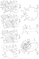
- FIG. 1 shows a perspective view of a fastening part with a first fastening element arranged thereon in the form of an annular elastic band
- FIG. 2 shows an end view of the fastening part shown in FIG. 1 with a first fastening element
- FIG. 3 shows a side view of the fastening part shown in FIG. 1 with a first fastening element
- FIG. 4 shows a view of part of the fastening part shown in FIG. 1 and the first fastening element and a second fastening element holding an energy guide in hose form
- FIG. 5 shows a view of part of the fastening part shown in FIG. 1 and the first fastening element and a second configuration of a second fastening element in the form of a protector, holding the tubular energy guide chain,
- FIG. 6 shows a view of part of the fastening part shown in FIG. 1 and the first fastening element and a third configuration of a second fastening element in the form of an intermediate connection in the form of a clamp for a tubular energy guide chain,
- FIG. 7 shows a view of part of the fastening part shown in FIG. 1 and the first fastening element and a fourth configuration of a second fastening element in the form of a connecting element in the form of a clamp for a tubular energy guide chain
- FIG. 8 shows a perspective view of an alternative embodiment for the fastening part and a first fastening element arranged thereon
- FIG. 9 shows an end view of the fastening part shown in FIG. 8 and the first fastening element
- FIG. 10 shows a side view of the fastening part shown in FIG. 8 and the first fastening element
- FIG. 11 shows a view of part of the fastening part shown in FIG. 8 and the first fastening element with a second fastening element in the form of a hook-and-loop fastener for a energy guide in the form of a hose,
- FIG. 12 shows a view of part of the fastening part shown in FIG. 8 and the first fastening element with a second configuration of the second fastening element in the form of a protector holding a tubular energy guide chain
- FIG. 13 shows a view of part of the fastening part shown in FIG. 8 and the first fastening element with a third configuration of the second fastening element in the form of a clamp for intermediate connection of a tubular energy guide chain, and
- FIG. 14 shows a view of part of the fastening part shown in FIG. 8 and the first fastening element with a fourth configuration of a second fastening element in the form of a connecting element for a tubular energy guide chain.
- the fastening parts 1 and 2 respectively are in the form of double-T-shaped integral parts produced in the form of plastic injection moldings.
- the upper T-limb forms the fastening web 3 and 4 respectively for fastening a second fastening element of differing configuration for an energy guide to be held to a robot arm.
- the lower T-limb forms the foot web or base web which in the embodiments being considered is in the form of a flexurally elastic web 5 and 6 respectively and serves for fastening a first fastening element 7 and 8 for fastening the fastening part 1 and 2 respectively to a robot arm as the component.
- the respective flexurally elastic web 5 and 6 is integrally connected to the associated fastening web 3 and 4 respectively by way of a connecting element 9 .
- the regions of the free ends of the fastening web have two constrictions 10 for being encircled with an annular elastic strand 11 which is passed around the energy guide, as the second fastening element which can be tightened around an energy guide 12 .
- the strand 11 is in the form of a rubber ring.
- the fastening web 3 has side regions 13 , 14 which extend beyond the connecting element 9 in its direction and which are arranged at a spacing relative to the flexurally elastic web 5 and respectively have two openings 15 spaced in the longitudinal direction for fastening other configurations of the second fastening element for the energy guide.
- the openings 15 can serve for fastening a clamp 16 for holding the energy guide, as the second fastening element, as shown in FIG. 6 , wherein the clamp 16 has a substantially flat fastening surface extending in the longitudinal direction of the fastening web 3 .
- the clamp 16 comprises two halves 17 and 18 which are made from plastic and are arranged in mutually superposed relationship. The two halves 17 and 18 are connected together pivotably in one of the lateral connecting regions so that they can be pivoted open for insertion of the energy guide and closed to hold it.
- a snap-action closure serves as a closure on the side opposite to the pivotal connection 19 .
- a clamp 20 serving as a connecting element serving as a second fastening element for clamping an end region of an energy guide, as shown in FIG. 7 .
- the clamp 20 serving as the connecting element is oriented in such a way that the latching closure 21 opposite the pivotal connection 19 can be seen between the upper half 22 and the lower half 23 .
- the clamp 20 is provided at the side facing away from the energy guide chain, around its central opening 24 , with tensile strain-relief elements 25 for the connection of the lines guided through the energy guide chain.
- the wear ring 27 comprises two ring halves 28 and 29 arranged in mutually superposed relationship on the fastening web 3 . In their two oppositely disposed connecting regions the two ring halves 28 and 29 are fastened together by a respective snap-action closure.
- the outside contour of the wear ring 27 is also convextly curved in the longitudinal direction so that there is a very low risk of injury as there are virtually no troublesome or cutting edges.
- the energy guides shown in FIGS. 5 through 7 are in the form of a tubular energy guide chain 30 .
- the connecting element 9 has recesses 31 with an interposed bar, acting as material recesses.
- the two openings 26 are arranged in the regions of the fastening web, that are above the recesses 31 .
- the flexurally elastic web 5 in the end regions thereof has holding means 32 for the first fastening element which is in the form of an annular elastic strand 7 .
- the holding means 32 are in the form of hook-shaped projections which are angled outwardly and towards the connecting element 9 .
- the projections 33 In a plane extending parallel to the flexurally elastic web 5 the projections 33 have a contact surface extending in an arc for the annular elastic strand which can be passed therearound, over which the angled ends 34 of the hook-shaped projections 33 extend.
- the hook-shaped projections 33 are formed in one piece on the fastening part 1 .
- the outside contour of the angled ends 34 of the hook-shaped projections 33 extends arcuately with an incision 35 which extends in aligned relationship with the contact surface for the annular elastic strand and into which a tool can engage from the outside for the purposes of releasing the elastic strand which is under tension where it is guided around the contact surface from its anchored state.
- the fastening web 4 in the region of its free ends has slots 36 extending transversely to its longitudinal direction for passing therethrough a hook-and-loop fastener 37 as a holder for the hose-like or tubular energy guide 12 .
- the two end regions 38 of the hook-and-loop fastener are passed from the exterior inwardly on to the flexurally elastic element 6 through the slots 36 in the fastening web, that extend transversely to the longitudinal direction, then deflected over the ends of the fastening web 4 and placed from the exterior in the respective peripheral direction over the hook-and-loop fastener which is drawn around the energy guide 12 and fastened thereto with the hook-and-loop closure regions 39 , as shown in FIG. 11 .
- slots 36 are provided with enlargements 39 which face in the longitudinal direction of the fastening part 4 and which, together with openings 15 spaced in the longitudinal direction of the fastening web 4 , serve for fastening the clamps 16 and 20 respectively shown in FIGS. 13 and 14 as holders for a tubular energy guide chain 30 .
- clamps 16 and 20 Mounting of the clamps 16 and 20 to the fastening web 4 is effected by the method described hereinbefore with reference to FIGS. 6 and 7 .
- the fastening web 4 in its central region, as in the embodiment shown in FIG. 1 , has two openings 26 which are spaced in the transverse direction and which serve for fastening a wear ring (protector) 27 shown in FIG. 12 .
- the web 6 in the region of its free ends has slots 40 which extend transversely to the longitudinal direction of the flexurally elastic web 4 and through which the hook-and-loop fastener extends.
- the two end regions 41 of the hook-and-loop fastener which is placed around the robot arm are guided from the inside through the slots 40 outwardly, deflected in the respective peripheral direction around holding webs provided between the slots 40 and the free ends of the flexurally elastic web that are adjacent thereto, drawn over the hook-and-loop fastener placed around the robot arm and fastened thereto by hook-and-loop fastener regions.
- Outwardly projecting lateral guide webs 42 for the hook-and-loop fastener are arranged at the sides of the slots 40 and holding webs, arranged transversely relative to the longitudinal direction of the flexurally elastic web 6 .
- the guide webs are formed in one piece on the flexurally elastic web 6 .
Landscapes
- Engineering & Computer Science (AREA)
- General Engineering & Computer Science (AREA)
- Mechanical Engineering (AREA)
- Architecture (AREA)
- Civil Engineering (AREA)
- Structural Engineering (AREA)
- Robotics (AREA)
- Clamps And Clips (AREA)
- Supports For Pipes And Cables (AREA)
- Mutual Connection Of Rods And Tubes (AREA)
- Installation Of Indoor Wiring (AREA)
Applications Claiming Priority (3)
| Application Number | Priority Date | Filing Date | Title |
|---|---|---|---|
| DE202019101830.5 | 2019-04-01 | ||
| DE202019101830.5U DE202019101830U1 (de) | 2019-04-01 | 2019-04-01 | Befestigungsteil |
| PCT/EP2020/058896 WO2020201181A1 (de) | 2019-04-01 | 2020-03-30 | Befestigungsteil |
Publications (2)
| Publication Number | Publication Date |
|---|---|
| US20220166202A1 US20220166202A1 (en) | 2022-05-26 |
| US11799277B2 true US11799277B2 (en) | 2023-10-24 |
Family
ID=66548031
Family Applications (1)
| Application Number | Title | Priority Date | Filing Date |
|---|---|---|---|
| US17/594,018 Active 2040-06-15 US11799277B2 (en) | 2019-04-01 | 2020-03-30 | Fastening part |
Country Status (7)
| Country | Link |
|---|---|
| US (1) | US11799277B2 (de) |
| EP (1) | EP3949050A1 (de) |
| JP (1) | JP7253073B2 (de) |
| KR (1) | KR102700510B1 (de) |
| CN (1) | CN114026760B (de) |
| DE (1) | DE202019101830U1 (de) |
| WO (1) | WO2020201181A1 (de) |
Families Citing this family (5)
| Publication number | Priority date | Publication date | Assignee | Title |
|---|---|---|---|---|
| DE102019108810B4 (de) * | 2019-04-04 | 2021-06-24 | HELLA GmbH & Co. KGaA | Griffelement zur Anordnung an einem Bauteil |
| EP4468540A1 (de) | 2023-05-22 | 2024-11-27 | ABB Schweiz AG | Kabelhalter für kollaboratives roboterkabelmanagement |
| WO2026035330A1 (en) * | 2024-08-07 | 2026-02-12 | Double LEB LLC | Systems and devices for mounting a thermostatic mixing valve and methods thereof |
| US12546097B1 (en) | 2024-08-07 | 2026-02-10 | Double Leb, LLC | Systems and devices for mounting a thermostatic mixing valve and methods thereof |
| WO2026078595A1 (en) * | 2024-10-11 | 2026-04-16 | ESAB Europe GmbH | Cable management system for welding system |
Citations (16)
| Publication number | Priority date | Publication date | Assignee | Title |
|---|---|---|---|---|
| US3539138A (en) | 1968-05-07 | 1970-11-10 | Philip J Desroches | Apparatus for supporting and connecting cylindrical members |
| US4460142A (en) * | 1982-02-04 | 1984-07-17 | Rorke Blondale O | Bracket for supporting a sign to a cylindrical post |
| US4659046A (en) * | 1986-02-24 | 1987-04-21 | Parduhn A Philip | Traffic control device mast arm bracket |
| JP2002373536A (ja) | 2001-06-14 | 2002-12-26 | Akira Saito | 絶縁保護シート |
| CA2429053A1 (en) | 1999-06-09 | 2004-11-20 | Denis E. Libecco | Adjustable elastic tie-down cord |
| US20050028326A1 (en) | 2003-08-06 | 2005-02-10 | Maurus Logan | Method and apparatus for securing cables and the like |
| EP2251553A1 (de) | 2009-05-04 | 2010-11-17 | Waldemar Rothe | Verbindungselement für Rohre, Verfahren zum Verbinden von Rohren und Verwendung des Verbindungselementes |
| US7997546B1 (en) | 2007-05-07 | 2011-08-16 | Pelco Products, Inc. | Mounting assembly for traffic cameras and other traffic control devices |
| DE102011116948B3 (de) | 2011-10-26 | 2013-04-04 | Hydac Accessories Gmbh | Bandschelle |
| CN203666541U (zh) | 2013-12-31 | 2014-06-25 | 安徽江淮汽车股份有限公司 | 一种随车工具的固定装置 |
| US9200654B1 (en) * | 2008-01-28 | 2015-12-01 | Pelco Products, Inc. | Mounting bracket for traffic control device |
| US20160009469A1 (en) | 2012-09-26 | 2016-01-14 | Tigre S.A. - Tubos E Conexões | Clamp for pipe fastening |
| WO2017220976A1 (en) | 2016-06-21 | 2017-12-28 | Advanced Insulation Plc | Mounting arrangement |
| CN207333965U (zh) | 2017-09-28 | 2018-05-08 | Tcl空调器(中山)有限公司 | 一种管道固定装置 |
| WO2018177482A1 (de) | 2017-03-31 | 2018-10-04 | Leoni Kabel Gmbh | Befestigungsvorrichtung für einen versorgungsschlauch und/oder eine versorgungsleitung zum befestigen an einem industrieroboterarm |
| DE102017117087A1 (de) | 2017-07-28 | 2019-01-31 | Murrplastik Systemtechnik Gmbh | Adapter und Vorrichtung zum Befestigen einer Leitung |
Family Cites Families (7)
| Publication number | Priority date | Publication date | Assignee | Title |
|---|---|---|---|---|
| US3917205A (en) * | 1974-04-08 | 1975-11-04 | Southwestern Electric Company | Connector for traffic signal lights |
| JP4274685B2 (ja) * | 2000-12-04 | 2009-06-10 | 本田技研工業株式会社 | ロボットのケーブル案内装置 |
| JP2008098421A (ja) * | 2006-10-12 | 2008-04-24 | Matsushita Electric Ind Co Ltd | リードクランパー |
| JP2009142918A (ja) * | 2007-12-12 | 2009-07-02 | Kwang-Sul Choi | 産業用ロボットのケーブルガイド装置 |
| JP5260082B2 (ja) * | 2008-02-26 | 2013-08-14 | 三菱重工業株式会社 | ターボチャージャの排気バイパス弁 |
| JP5660921B2 (ja) * | 2011-01-19 | 2015-01-28 | 未来工業株式会社 | 配線・配管材保持具および配線・配管材の固定方法 |
| JP6079399B2 (ja) * | 2013-04-16 | 2017-02-15 | 住友電装株式会社 | ワイヤハーネスおよびコネクタ部材 |
-
2019
- 2019-04-01 DE DE202019101830.5U patent/DE202019101830U1/de active Active
-
2020
- 2020-03-30 JP JP2021556487A patent/JP7253073B2/ja active Active
- 2020-03-30 EP EP20716418.7A patent/EP3949050A1/de active Pending
- 2020-03-30 WO PCT/EP2020/058896 patent/WO2020201181A1/de not_active Ceased
- 2020-03-30 US US17/594,018 patent/US11799277B2/en active Active
- 2020-03-30 CN CN202080026668.7A patent/CN114026760B/zh active Active
- 2020-03-30 KR KR1020217034752A patent/KR102700510B1/ko active Active
Patent Citations (17)
| Publication number | Priority date | Publication date | Assignee | Title |
|---|---|---|---|---|
| US3539138A (en) | 1968-05-07 | 1970-11-10 | Philip J Desroches | Apparatus for supporting and connecting cylindrical members |
| US4460142A (en) * | 1982-02-04 | 1984-07-17 | Rorke Blondale O | Bracket for supporting a sign to a cylindrical post |
| US4659046A (en) * | 1986-02-24 | 1987-04-21 | Parduhn A Philip | Traffic control device mast arm bracket |
| CA2429053A1 (en) | 1999-06-09 | 2004-11-20 | Denis E. Libecco | Adjustable elastic tie-down cord |
| JP2002373536A (ja) | 2001-06-14 | 2002-12-26 | Akira Saito | 絶縁保護シート |
| US20050028326A1 (en) | 2003-08-06 | 2005-02-10 | Maurus Logan | Method and apparatus for securing cables and the like |
| US7997546B1 (en) | 2007-05-07 | 2011-08-16 | Pelco Products, Inc. | Mounting assembly for traffic cameras and other traffic control devices |
| US9200654B1 (en) * | 2008-01-28 | 2015-12-01 | Pelco Products, Inc. | Mounting bracket for traffic control device |
| EP2251553A1 (de) | 2009-05-04 | 2010-11-17 | Waldemar Rothe | Verbindungselement für Rohre, Verfahren zum Verbinden von Rohren und Verwendung des Verbindungselementes |
| DE102011116948B3 (de) | 2011-10-26 | 2013-04-04 | Hydac Accessories Gmbh | Bandschelle |
| US20160009469A1 (en) | 2012-09-26 | 2016-01-14 | Tigre S.A. - Tubos E Conexões | Clamp for pipe fastening |
| CN203666541U (zh) | 2013-12-31 | 2014-06-25 | 安徽江淮汽车股份有限公司 | 一种随车工具的固定装置 |
| WO2017220976A1 (en) | 2016-06-21 | 2017-12-28 | Advanced Insulation Plc | Mounting arrangement |
| WO2018177482A1 (de) | 2017-03-31 | 2018-10-04 | Leoni Kabel Gmbh | Befestigungsvorrichtung für einen versorgungsschlauch und/oder eine versorgungsleitung zum befestigen an einem industrieroboterarm |
| US20200055201A1 (en) | 2017-03-31 | 2020-02-20 | Leoni Kabel Gmbh | Fastening device for a supply hose and/or a supply line for fastening to an industrial-robot arm |
| DE102017117087A1 (de) | 2017-07-28 | 2019-01-31 | Murrplastik Systemtechnik Gmbh | Adapter und Vorrichtung zum Befestigen einer Leitung |
| CN207333965U (zh) | 2017-09-28 | 2018-05-08 | Tcl空调器(中山)有限公司 | 一种管道固定装置 |
Non-Patent Citations (3)
| Title |
|---|
| International Preliminary Report on Patentability from corresponding PCT Appln. No PCT/EP2020/058896, dated Mar. 30, 2020. |
| International Search Report from corresponding PCT Appln. No. PCT/EP2020/058896, dated May 12, 2020. |
| Office Action from related Chinese Appln. No. 202080026668.7, dated Feb. 11, 2023. |
Also Published As
| Publication number | Publication date |
|---|---|
| JP7253073B2 (ja) | 2023-04-05 |
| CN114026760B (zh) | 2023-09-22 |
| DE202019101830U1 (de) | 2019-04-29 |
| CN114026760A (zh) | 2022-02-08 |
| US20220166202A1 (en) | 2022-05-26 |
| KR102700510B1 (ko) | 2024-08-30 |
| WO2020201181A1 (de) | 2020-10-08 |
| JP2022526745A (ja) | 2022-05-26 |
| KR20210145216A (ko) | 2021-12-01 |
| EP3949050A1 (de) | 2022-02-09 |
Similar Documents
| Publication | Publication Date | Title |
|---|---|---|
| US11799277B2 (en) | Fastening part | |
| US4898542A (en) | Anti-separation coaxial connector tie-straps | |
| US20030041417A1 (en) | Rubber band retainer apparatus | |
| US3672615A (en) | Strap support | |
| US20130067695A1 (en) | Wide Cushioned Cable Tie for Optical Fiber Bundle | |
| US5093964A (en) | Clip for holding flexible elements such as wire, hose, etc. | |
| CA2694077C (en) | Cable guide | |
| SE530939C2 (sv) | Buntband | |
| US6473945B1 (en) | Flange clamp | |
| US5666709A (en) | Balloon clip fastening device | |
| ITTO20010764A1 (it) | Fascetta di fissaggio reversibile, in particolare per il cablaggio dicavi elettrici su veicoli. | |
| DE3876916D1 (de) | Energiefuehrungskette. | |
| EP0888658A1 (de) | Träger klammer | |
| US9969449B2 (en) | Holder for a two-wheeler accessory | |
| KR200480016Y1 (ko) | 공용화 공체 클립 | |
| CN209796296U (zh) | 束线带 | |
| KR101956199B1 (ko) | 와이어 하네스용 분기 클립장치 | |
| KR101707190B1 (ko) | 풍선 매듭 결착용 바인더 | |
| EP4468540A1 (de) | Kabelhalter für kollaboratives roboterkabelmanagement | |
| JP2004120955A (ja) | ケーブル結束保持具 | |
| KR200367392Y1 (ko) | 원형고무밴드용 체결부재 | |
| CA1219246A (en) | Cable clamp | |
| EP0336654A2 (de) | Halterung eines biegsamen Elementes | |
| DE59811993D1 (de) | Verwendung eines Verbindungselements für Flansche an Behältermündungen von Laborgeräten | |
| US20070158505A1 (en) | Retaining device |
Legal Events
| Date | Code | Title | Description |
|---|---|---|---|
| FEPP | Fee payment procedure |
Free format text: ENTITY STATUS SET TO UNDISCOUNTED (ORIGINAL EVENT CODE: BIG.); ENTITY STATUS OF PATENT OWNER: LARGE ENTITY |
|
| STPP | Information on status: patent application and granting procedure in general |
Free format text: DOCKETED NEW CASE - READY FOR EXAMINATION |
|
| AS | Assignment |
Owner name: IGUS GMBH, GERMANY Free format text: ASSIGNMENT OF ASSIGNORS INTEREST;ASSIGNORS:STEEGER, RALF;OTTERSBACH, JOERG;SIGNING DATES FROM 20210919 TO 20210922;REEL/FRAME:061238/0001 |
|
| STPP | Information on status: patent application and granting procedure in general |
Free format text: NOTICE OF ALLOWANCE MAILED -- APPLICATION RECEIVED IN OFFICE OF PUBLICATIONS |
|
| STPP | Information on status: patent application and granting procedure in general |
Free format text: PUBLICATIONS -- ISSUE FEE PAYMENT RECEIVED |
|
| STPP | Information on status: patent application and granting procedure in general |
Free format text: PUBLICATIONS -- ISSUE FEE PAYMENT VERIFIED |
|
| STCF | Information on status: patent grant |
Free format text: PATENTED CASE |