US11299858B2 - Method for unloading, transporting and installing a railway track - Google Patents
Method for unloading, transporting and installing a railway track Download PDFInfo
- Publication number
- US11299858B2 US11299858B2 US16/310,027 US201716310027A US11299858B2 US 11299858 B2 US11299858 B2 US 11299858B2 US 201716310027 A US201716310027 A US 201716310027A US 11299858 B2 US11299858 B2 US 11299858B2
- Authority
- US
- United States
- Prior art keywords
- unloading
- rails
- rail
- track
- elements
- Prior art date
- Legal status (The legal status is an assumption and is not a legal conclusion. Google has not performed a legal analysis and makes no representation as to the accuracy of the status listed.)
- Active, expires
Links
Images


Classifications
-
- E—FIXED CONSTRUCTIONS
- E01—CONSTRUCTION OF ROADS, RAILWAYS, OR BRIDGES
- E01B—PERMANENT WAY; PERMANENT-WAY TOOLS; MACHINES FOR MAKING RAILWAYS OF ALL KINDS
- E01B29/00—Laying, rebuilding, or taking-up tracks; Tools or machines therefor
- E01B29/16—Transporting, laying, removing, or replacing rails; Moving rails placed on sleepers in the track
- E01B29/17—Lengths of rails assembled into strings, e.g. welded together
-
- B—PERFORMING OPERATIONS; TRANSPORTING
- B66—HOISTING; LIFTING; HAULING
- B66C—CRANES; LOAD-ENGAGING ELEMENTS OR DEVICES FOR CRANES, CAPSTANS, WINCHES, OR TACKLES
- B66C23/00—Cranes comprising essentially a beam, boom, or triangular structure acting as a cantilever and mounted for translatory of swinging movements in vertical or horizontal planes or a combination of such movements, e.g. jib-cranes, derricks, tower cranes
- B66C23/18—Cranes comprising essentially a beam, boom, or triangular structure acting as a cantilever and mounted for translatory of swinging movements in vertical or horizontal planes or a combination of such movements, e.g. jib-cranes, derricks, tower cranes specially adapted for use in particular purposes
- B66C23/36—Cranes comprising essentially a beam, boom, or triangular structure acting as a cantilever and mounted for translatory of swinging movements in vertical or horizontal planes or a combination of such movements, e.g. jib-cranes, derricks, tower cranes specially adapted for use in particular purposes mounted on road or rail vehicles; Manually-movable jib-cranes for use in workshops; Floating cranes
- B66C23/50—Cranes comprising essentially a beam, boom, or triangular structure acting as a cantilever and mounted for translatory of swinging movements in vertical or horizontal planes or a combination of such movements, e.g. jib-cranes, derricks, tower cranes specially adapted for use in particular purposes mounted on road or rail vehicles; Manually-movable jib-cranes for use in workshops; Floating cranes mounted on railway vehicles, e.g. breakdown cranes
-
- E—FIXED CONSTRUCTIONS
- E01—CONSTRUCTION OF ROADS, RAILWAYS, OR BRIDGES
- E01B—PERMANENT WAY; PERMANENT-WAY TOOLS; MACHINES FOR MAKING RAILWAYS OF ALL KINDS
- E01B29/00—Laying, rebuilding, or taking-up tracks; Tools or machines therefor
- E01B29/02—Transporting, laying, removing, or renewing lengths of assembled track, assembled switches, or assembled crossings
-
- E—FIXED CONSTRUCTIONS
- E01—CONSTRUCTION OF ROADS, RAILWAYS, OR BRIDGES
- E01B—PERMANENT WAY; PERMANENT-WAY TOOLS; MACHINES FOR MAKING RAILWAYS OF ALL KINDS
- E01B29/00—Laying, rebuilding, or taking-up tracks; Tools or machines therefor
- E01B29/16—Transporting, laying, removing, or replacing rails; Moving rails placed on sleepers in the track
- E01B29/20—Moving rails placed on installed sleepers in the plane track
-
- E—FIXED CONSTRUCTIONS
- E01—CONSTRUCTION OF ROADS, RAILWAYS, OR BRIDGES
- E01B—PERMANENT WAY; PERMANENT-WAY TOOLS; MACHINES FOR MAKING RAILWAYS OF ALL KINDS
- E01B33/00—Machines or devices for shifting tracks, with or without lifting, e.g. for aligning track, for shifting excavator track
Definitions
- the invention is related to the technical sector for the maintenance and construction of railway infrastructure. More precisely, it is related to a method for unloading, transporting and installing the rails from a rail-carrying train and it positioning at the place of installation.
- the procedure historically employed to transport the rails to be laid on a railroad track was to use a provisional track, comprised of wooden sleepers and second use rails.
- the length of this track for assembling a span of double track is 2,900 meters in spans of 12 meters to optimize its transport.
- the rail-carrying train is the means through which the rails usually arrive to the assembly area of the railroad tracks.
- One of the most analyzed activities within the railroad track assembly process is the unloading of the rails from the rail-carrying train.
- a previously assembled track is required, which can be a track to be replaced or an auxiliary track.
- the rail-carrying train remains stationary on the track, which may be the new track previously laid, and the new rail is removed, which is placed as a continuation of this previously assembled track.
- This second working method has the advantage of not requiring an auxiliary track or a previously assembled track.
- the present invention provides a method for transporting and transferring railway track comprising the following steps:
- This invention achieves a performance clearly superior to that of conventional processes, thanks to the substantial increase in the number of cycles per production day and the release of material assets that are essential in all known systems, substantially reducing the cost of installing the railway tracks.
- This method does not require pulling the rail-carrying train after each unloading cycle of continuous welded rail (CWR), rather the rail-carrying train is stationary at the end of the previously assembled track and does not need to be moved until the unloading of all CWR on the rail-carrying train is finished.
- CWR continuous welded rail
- the versatility of the present invention allows the unloading of rails on sleepers placed on the ballast bed, and particularly on the concrete slab of tunnels, which allows the CWR to be distributed along the tunnel for subsequent plate mounting.
- Another type of advantages of this invention are the environmental ones, since it diminishes the environmental impact on air quality, since it reduces the pollution load, through the reduction of exhaust gas emissions. Proportionally, the environmental impact on the consumption of energy resources is also reduced.
- this new method ostensibly improves the sanitary conditions of the operators of the assembly process, especially when it comes to carrying out the unloading of rails in the form of CWR for the installation of slab track inside tunnels or other confined spaces.
- the disappearance of exhaust gas emitted by the traction locomotives of the rail-carrying train translates into a substantial improvement in air quality and a clear reduction in the need for ventilation.
- FIG. 1 shows a front view of the puller machine where the railway wheels are seen resting on the rails, while the driving elements of the frame are in the air.
- FIG. 2 shows a side view of the puller machine where the railway wheels are seen resting on the rails, while the driving elements of the frame are in the air, and where the transverse beam for tying and pulling and the hinged arm with the clamp for rails is seen.
- FIG. 2A shows, with reference to the previous Figure, an enlargement of the tying element.
- FIG. 3 shows a front view of the puller machine where the railway wheels are seen in the air, not resting on the rails, while the driving elements of the frame are on the ground.
- FIG. 4 shows a side view of the puller machine where the railway wheels are seen in the air, not resting on the rails, while the driving elements of the frame remain resting on the ground, and where the transverse beam for tying and pulling and the hinged arm with the clamp for rails is seen.
- FIG. 5 shows a plan view of the unloading wagon.
- FIG. 6A shows an elevation view of the unloading wagon, where the crane can be seen at one end, while FIG. 6B shows the other end of the unloading with the puller machine supporting said unloading.
- FIG. 6C shows an enlarged detail with respect to FIG. 6A where the support elements appear next to other elements, while FIG. 6D shows the lighting tower in greater detail, also in relation to FIG. 6A .
- FIG. 7 shows a front view of an example support element of greater height, which could be located at the beginning of the rail unloading point.
- the Figure shows the lighting tower which can be incorporated to the wagon.
- FIG. 8 shows a front view of an example support element of medium height, related to the one above.
- FIG. 9 shows a front view of an example support element of lesser height, which could be located at the end of the unloading point on the wagon.
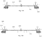
- FIG. 10A shows a front view of a transport element of the railway track transport and transfer system.
- the element is arranged for a narrow track width.
- FIG. 10B shows a front view of the same transport element of the previous Figure arranged for a track width that is wider than the one above.
- FIG. 11A shows the top view of the transport element of the railway track transport and transfer system, in which the pivoting beam remains perpendicular to the direction of the track.
- FIG. 11B shows the top view of the transport element of the railway track transport and transfer system, in which the pivoting beam is rotated to adapt to the curvature of the rail and the track when it is moving along the existing track.
- FIG. 12A shows a top view of the transfer element of the railway track transport and transfer system.
- FIG. 12B shows a front view of the transfer element of the railway track transport and transfer system.
- FIG. 12C shows a side view of the transfer element of the railway track transport and transfer system where the system of connecting rods and drive is observed in an elevated position with respect to the horizontal.
- FIG. 13 shows a side view of a section of the deployment of the railway track transport and transfer system; specifically, the rail that is transported by the transport elements and is already elevated above the transfer element.
- FIG. 14 shows a side view of another section of the deployment of the railway track transport and transfer system; specifically, the rail that is elevated above the transfer element and slid over the sliding elements by pulling with a traction element.
- FIG. 15 shows a side view of another section of the deployment of the railway track transport and transfer system; specifically, the rail that is elevated above the transfer element and slid over the sliding elements by pulling with the traction element, but that, once the rail has reached its final position, it is observed how said traction element elevates the rail by the crane which is incorporated to remove the sliding elements and leave the rail resting on the sleepers.
- FIG. 15A shows an enlargement with the detail of the above figure of the sliding elements.
- FIGS. 16A and 16B show elevation views of the transfer element in two different moments: when pulling the rail, FIG. 16B , and when lifting the assembled rail to recover the transport elements, FIG. 16B .
- FIG. 17 shows the recovery of the translation elements once the operation of unloading and installing the rail is finished.
- the method described below supports a railway track transport and transfer system, consisting of a puller machine for the unloading and placement of railway tracks, a wagon for unloading said railway tracks and elements for the transport and transfer of the rails to the point of installation.
- the puller machine ( 1100 ) makes it possible to unload and lay the railway tracks, which arrive on a rail-carrying train, quickly, safely and precisely.
- the puller machine ( 1100 ) is comprised of several parts that differ based on the function to be performed:
- the puller machine ( 1100 ) has a first part formed by a frame ( 110 ) widened to a distance that allows the circulation of the driving elements ( 120 ) bordering the sleepers placed along the track, and the driving elements ( 120 ) that will be used to move the puller machine ( 1100 ) when the needs of adhesion and fraction are high and it is necessary to drag a pair of rails in the configuration of continuous welded rail (CWR) with a length of up to 270 m.
- CWR continuous welded rail
- the energy required for the movement of the puller machine ( 1100 ) is provided by a diesel engine ( 150 ) which drives hydraulic pumps that transform mechanical energy to hydraulic energy that is transmitted to the motors joined to the driving elements ( 120 ) that will transform the hydraulic energy received into mechanical energy by driving the rotation of said driving elements ( 120 ).
- said driving elements ( 120 ) are of the caterpillar type, mainly for outdoor and irregular terrain, whereas in another embodiment, said driving elements ( 120 ) are made of rubber, mainly when the deployment of railway track is carried out in tunnels with a concrete base.
- the tying elements ( 140 ) for the rail, lugs, flanges and shackles are commercial and foreign to this invention.
- This transverse beam ( 130 ) can be adjusted in height by means of hydraulic bottles attached to the frame ( 110 ) of the puller machine ( 1100 ), and serves to bridge the longitudinal levelling irregularities on the platform or ballast bed. Actuating them upwards in such a way that the end of the rails is higher than the sliding rollers, such that part of the weight of these rail ends will rest on the traction elements, thus improving their adherence if the traction effort to be carried out requires it.
- the device By means of an articulated arm ( 160 ) with a rail clamp ( 170 ) at the end, as a lifting crane, the device carries out the operation of lifting the rail for the recovery of the rail sliding elements placed on the sleepers, the rollers, and the placement of the rail on the sleeper, once the roller has been removed.
- the puller machine ( 1100 ) In order to speed up the movement of the machine and the transport of the sliding elements, the puller machine ( 1100 ) has been equipped with four railway wheels ( 180 ), with the possibility of adapting to the different track widths, which are hydraulically driven, allowing the puller machine ( 1100 ) to swiftly move along the already assembled track when the traction needs are not so demanding, i.e., throughout the whole process except when dragging the track pairs.
- These four wheels ( 180 ) move vertically with respect to the frame ( 110 ) of the puller machine ( 1100 ), so that once resting on the upper surface of the rails, the caterpillars ( 120 ) or rubber wheels ( 120 ) used to split the rail remain in the air, and the movement of the puller machine ( 1100 ) is carried out by these railway wheels ( 180 ).
- It consists of a wagon ( 2100 ) or platform suitable for travelling on railway tracks, equipped with railway mounted axles ( 210 ), suitable for circulation on railway tracks of different widths, which is coupled to the rail-carrying train at the unloading end of the rails.
- this unloading wagon ( 2100 ) or platform is to avoid deflections of the railcar during the unloading, which can produce permanent deformations therein.
- variable height ( 220 ) support elements installed on its upper surface, which serve as a guide to lead the rails from the platform of the rail-carrying train to the transport elements.
- the wagon ( 2100 ) therefore, facilitates the unloading of the rails in pairs of predetermined length (e.g., 270 meters in length), through the support elements ( 220 ) that serve as a guide to lead the rails in a parallel way on the fastenings which receive them and direct them to the transport elements.
- predetermined length e.g., 270 meters in length
- the support elements ( 220 ) can be regulated in height, which makes it easier to adapt the rail from its variable position on the rail-carrying train, and they have vertical and horizontal rolls ( 290 ) which facilitate the job of the puller machine ( 1100 ) for moving the rail forward minimizing the friction between the rail and the support element ( 220 ).
- the wagon ( 2100 ) or unloading platform has a crane ( 230 ) to easily move the slings of twisted wire used to transmit the traction effort to the rail in the first phase of unloading.
- said crane ( 230 ) is ready to fold and deploy and, in its maximum deployment phase, it is ready to reach the support element ( 220 ) that is the furthest from this wagon ( 2100 ).
- the unloading wagon ( 2100 ) can be used to transport materials by using the crane ( 230 ) of the slings as a tool for loading and unloading materials and to facilitate in the same way the unloading of small dimensions and other consumables.
- the wagon ( 2100 ) also functions as a storage hangar for the transport element ( 310 ) of the rail.
- the transport elements ( 310 ) are set aside on a cased track ( 240 ) or additional track on the platform of the wagon itself ( 2100 ), which has a ramp ( 280 ) made up of two longitudinally collapsible rail coupons, cut in wedges to allow the transport element ( 310 ) to pass from the wagon to the assembly track, i.e., the wagon ( 2100 ) has said cased track ( 240 ) on its upper portion, in which said translation transport elements ( 310 ) are stored.
- the wagon ( 2100 ) allows driving the rail from its location on the rail-carrying train to the transport elements and, in addition, doing it without allowing it to flex, which can cause the permanent deformations; this element serves as a guide for the rails.
- Driving is achieved as the puller machine ( 1100 ) pulls the rail for unloading it from the rail-carrying train, through support elements ( 220 ) which are adjustable in height, through which the end of the rail is passed.
- the energy necessary for moving the crane is given by a power-pack or connected power unit ( 260 ) and a generating set powered by a diesel engine.
- This connected power unit ( 260 ) and generating set can also power a lighting tower ( 270 ) that allows these tasks to be carried out in low visibility conditions, whether they are carried out at night or inside tunnels.
- the translation of the track rails to their final position in the installation is carried out in several stages, for each of which different but related and coordinated means of transport are used.
- the rails are carried from the rail-carrying train and the unloading wagon by transport elements ( 310 ) moving on existing track.
- transport elements ( 310 ) moving on existing track.
- this track ends and, therefore, the point is reached where there are sleepers on which to place the new rails, there are sliding elements ( 330 ) placed on the sleepers themselves on which the rails are to slide.
- This rail transport is from the rear or end point of the unloading wagon next to the parked rail-carrying train to the transfer element ( 320 ). To this end, the rail is loaded on said transport elements ( 310 ) and these are the ones that transport the rail on the assembled track, where the force necessary for movement is exerted by the puller machine ( 1100 ).
- the rails are directed towards a pivoting beam ( 313 ) installed in the transport elements ( 310 ) at the end of which a there is a guide ( 314 ) on which the rails of the track are placed for transport.
- the distance between transport elements ( 310 ) and, therefore, the number of transport elements ( 310 ) required to support the weight of the section supported may vary.
- Each of the transport elements ( 310 ) of rail or tanks consists of a pivoting beam ( 313 ) designed to receive the pair of rails on its upper surface, where this beam ( 313 ) is prepared to accommodate and stabilize the rails supported during their transfer.
- the beam ( 313 ) pivots on a vertical central axis ( 315 ) which is fixed to the frame ( 311 ) of the transport element ( 310 ), where this pivoting movement facilitates circulation, allowing it to adapt to different curvatures.
- the frame ( 311 ) is rigid and is equipped with four railway wheels ( 312 ) which allow it to roll on the rail, while these wheels ( 312 ) have a “double tab”.
- the contact of these tabs with the side faces of the rail head guides the transport elements ( 310 ) on the existing track when they are dragged by the supported rail that rests on them.
- the constructive form chosen for these transport elements ( 310 ) makes them suitable for circulation on different track widths, and in particular on the three track widths used in Spain.
- the frame ( 311 ) in its center zone, is disposed so as to increase or decrease in size.
- the system has sliding elements ( 330 ) with rollers previously placed on the sleepers without track at a mounting distance on the basalt bed. These elements with rollers ( 330 ) allow the rail to slide with little friction without the need to have a mobile element moving in the area of trackless sleepers.
- the transfer of the rail from the transport elements ( 310 ) to these sliding elements is carried out by means of a continuous transfer element ( 320 ), which, taking advantage of the pulling force of the puller machine ( 1100 ), said horizontal pull is transformed by the transfer element ( 320 ) into a force with a vertical component which causes the rail to be raised in such a way that it no longer rests on the pivoting beam ( 313 ) of the transport element ( 310 ).
- This mechanical system of continuous transfer ( 320 ) is equipped with rail guiding and sliding devices ( 326 ), which lead it to the sliding elements ( 330 ).
- This device or continuous transfer element ( 320 ) is placed at the end of the assembled track, on a frame ( 324 ) including railroad wheels ( 325 ). It is equipped with a mechanical system of connecting rods and actuations. This system of connecting rods ( 321 ) and actuations ( 322 ), in its initial end position, is folded on the horizontal plane, and allows transit over the puller machine ( 1100 ) that is making the pulling effort during the transport of the rails on the transport elements ( 310 ).
- the actuation ( 322 ) may be a hydraulic system supported by a diesel engine ( 323 ).
- the connecting rod ( 321 ) which rotates on an axis fixed to the frame ( 324 ), starts to move, which causes the sliding element ( 330 ) on its end to contact the lower face of the conveyed rail or rail skid. As the connecting rod ( 321 ) continues to rotate, its end begins to exert a vertical component force that causes the rail to raise, separating it from the transport element ( 310 ), thus stopping said transport element ( 310 ) from being dragged along the rail and stopping against a stop installed at the edge of the transfer element ( 320 ).
- the rail When the actuation ( 322 ) and the connecting rod ( 321 ) reach their final position, the rail will be suspended between the end of the connecting rod ( 321 ) of the transfer device ( 320 ) and the support of the dragged transport element ( 310 ), where the rail describes, due to its own weight, a catenary curve.
- the elevation of the connecting rod ( 321 ) is such that the vertical projection of this catenary on the rolling plane of the transport elements ( 310 ) has a length of at least the sum of the lengths of all the transport elements ( 310 ) that transport the CWR, so that they stop in the span of track assembled prior to the transfer element ( 320 ).
- the sliding elements ( 330 ) of rail are arranged on the sleepers with rollers. Each of these sliding elements ( 330 ) is extended to form a bridge between two consecutive sleepers, spaced by a previously defined spacing.
- Each of these sliding elements ( 330 ) consists of a steel plate or metal profile of such length that it can be extended between sleepers and fixed to two consecutive sleepers as a bridge. This profile is fixed to a roller that is responsible for enabling the movement of a rail, supported on it, during its longitudinal movement in the direction of installation.
- the sliding elements ( 330 ) with these rollers are arranged on both sides of the sleeper, for each rail, successively keeping a certain equidistance.
- the puller machine ( 1100 ) is equipped with crane means, the rail lifting operation is carried out supported on them, for the recovery of the rollers or sliding elements.
- the puller machine ( 1100 ) also has side trays which, like saddlebags on the machine chassis, allow the storage and transport of other components, such as, for example, the sliding elements ( 330 ) for the rails.
- the method for transporting and transferring railway track comprises the following steps:
- the slings of the rail are released and the traction element or puller machine ( 1100 ) approaches the head of the rail and the pulling flange is directly attached to the cross beam ( 130 ) of the element, traction device or puller machine ( 1100 ).
- the puller machine ( 1100 ) begins to move longitudinally away from the unloading wagon ( 2100 ), dragging the rails; as the rail advances, the transport elements ( 310 ) are rolled one by one from the unloading wagon ( 2100 ) to the track assembled by the ramps ( 280 ) placed at the end of the wagon ( 2100 ), and they are inserted under the rails, supporting their weight and enabling, with their wheels ( 312 ), their transport.
- the transport elements ( 310 ) are placed equidistant, at a distance such that the rail, depending on its own weight, does not flex excessively due to the action of gravity. In addition, spacers will be fitted between rails to strengthen the pair of rails and to prevent the rail from tipping over. The puller machine ( 1100 ) will continue to move away until the rails exit the unloading wagon ( 2100 ) completely and are only supported on transport elements ( 310 ).
- the transport elements ( 310 ) then roll along the assembled track, pulled by the puller machine ( 1100 ) to the transfer element ( 320 ).
- the transport elements ( 310 ) can no longer transport the CWR on the existing track; then, the track will cease to be transported by the transport elements ( 310 ) and will be dragged using elements that make it easier to slide.
- These sliding elements ( 330 ) incorporate rollers and have previously been placed on the sleepers that have been previously placed and at a mounting distance on the ballast bed.
- Transfer element ( 320 ) Continuous transfer from the rail transport system ( 310 ) to the rail sliding element ( 330 ) is carried out via transfer element ( 320 ), which, taking advantage of the pulling force of the puller machine ( 1100 ), is transformed by the transfer element ( 320 ) into a force with a vertical component which causes the rail to be raised in such a way that it no longer rests on the pivoting beam ( 313 ) of the transport element ( 310 ).
- the rail sliding elements ( 330 ) are arranged on top of them, with their rollers, each of them extended to form a bridge between two consecutive sleepers as mentioned above, and spaced by a previously defined spacing.
- the pair of rails is transferred from the transport elements ( 310 ) to the sliding rollers, the rails being directed and guided towards their support on the rollers or sliding elements ( 330 ) that were previously placed on the sleepers of the track.
- a cutting, squaring and flanging operation is carried out, i.e., an operation to join the ends of the rails immediately adjacent to each other.
- the rail on each side is lifted to recover the rollers or sliding elements ( 330 ) that allowed the longitudinal movement of each rail.
- This operation is carried out with the lifting equipment or crane ( 160 ) incorporated in the puller machine ( 1100 ), and it consists of lifting the rail, held at one end, the free end, to allow for the recovery of the aforementioned sliding elements ( 330 ), which are then loaded into the puller machine ( 1100 ) itself, as mentioned above, for transport to the new working position.
- one sleeper every certain number of units for example, one sleeper every 7 units.
- the puller machine ( 1100 ) traces back its steps to the unloading wagon ( 2100 ) moving on the assembled track using the railway wheels ( 180 ) of variable track width available and finishes nailing, all components and devices being ready for the beginning of a new cycle.
- the transfer element ( 320 ) When it reaches the transfer element ( 320 ), it must change its sliding mode to the caterpillars ( 120 ) or rubber wheels ( 120 ) and pass the transfer element ( 320 ) that is folded. Once passed, it rests on its railway wheels ( 180 ) and returns to the unloading wagon ( 2100 ), pushing the transport elements ( 310 ), which have previously been tied to each other, to prevent them from rolling out of control in the event of a favorable slope.
- the transport elements ( 310 ) Once the transport elements ( 310 ) reach the unloading wagon, they begin to ascend to it platform by means of the ramps ( 280 ) prepared for this purpose. As the puller machine ( 1100 ) approaches the unloading wagon ( 2100 ), the transport elements ( 310 ) are coupled to the platform, until the puller machine ( 1100 ) is in position to begin the cycle and all transport elements ( 310 ) are on the platform of the unloading wagon ( 2100 ).
Landscapes
- Engineering & Computer Science (AREA)
- Architecture (AREA)
- Civil Engineering (AREA)
- Structural Engineering (AREA)
- Mechanical Engineering (AREA)
- Machines For Laying And Maintaining Railways (AREA)
- Train Traffic Observation, Control, And Security (AREA)
Applications Claiming Priority (3)
| Application Number | Priority Date | Filing Date | Title |
|---|---|---|---|
| ES201630810A ES2646752B1 (es) | 2016-06-14 | 2016-06-14 | Método para descarga, transporte e instalación de carril de vía de ferrocarril |
| ESP201630810 | 2016-06-14 | ||
| PCT/ES2017/070407 WO2017216405A1 (es) | 2016-06-14 | 2017-06-05 | Método para descarga, transporte e instalación de carril de vía de ferrocarril |
Publications (2)
| Publication Number | Publication Date |
|---|---|
| US20190330804A1 US20190330804A1 (en) | 2019-10-31 |
| US11299858B2 true US11299858B2 (en) | 2022-04-12 |
Family
ID=60664015
Family Applications (1)
| Application Number | Title | Priority Date | Filing Date |
|---|---|---|---|
| US16/310,027 Active 2039-03-14 US11299858B2 (en) | 2016-06-14 | 2017-06-05 | Method for unloading, transporting and installing a railway track |
Country Status (13)
| Country | Link |
|---|---|
| US (1) | US11299858B2 (es) |
| EP (1) | EP3470576B8 (es) |
| CA (1) | CA3034174A1 (es) |
| CL (1) | CL2018003618A1 (es) |
| CO (1) | CO2019000352A2 (es) |
| DK (1) | DK3470576T3 (es) |
| ES (2) | ES2646752B1 (es) |
| HR (1) | HRP20221460T1 (es) |
| LT (1) | LT3470576T (es) |
| PE (1) | PE20190548A1 (es) |
| PT (1) | PT3470576T (es) |
| SI (1) | SI3470576T1 (es) |
| WO (1) | WO2017216405A1 (es) |
Families Citing this family (1)
| Publication number | Priority date | Publication date | Assignee | Title |
|---|---|---|---|---|
| CN108468256A (zh) * | 2018-02-06 | 2018-08-31 | 中车工业研究院有限公司 | 一种铁路智能扣件安装机械臂及其扣件安装方法 |
Citations (10)
| Publication number | Priority date | Publication date | Assignee | Title |
|---|---|---|---|---|
| US3465687A (en) | 1966-11-18 | 1969-09-09 | New York Central Railroad Co T | Rail positioning system |
| WO1998013551A1 (en) | 1996-09-09 | 1998-04-02 | Karl Anders Rosenqvist | A method of placing rail sections and a means therefore |
| ES1057004U (es) | 2004-03-18 | 2004-06-01 | Tecsa Empresa Constructora, S.A. | Util para descarga y posicionamiento de carriles en vias ferreas. |
| US20050172849A1 (en) | 2004-02-06 | 2005-08-11 | Herzog Contracting Corp. | Method and apparatus for unloading ribbon rails from rail cars |
| ES2308954A1 (es) | 2008-07-29 | 2008-12-01 | Tecsa Empresa Constructora, S.A | Maquina para la carga y descarga de rodillos de arrastre y posicionamiento de vias ferreas. |
| ES2361309A1 (es) | 2009-06-23 | 2011-06-16 | Fcc Construcicon S.A. | Procedimiento de instalación de vía férrea, sobre balasto, sin vía auxiliar. |
| US20120145032A1 (en) * | 2009-08-21 | 2012-06-14 | Herzog Contracting Corp. | Rail train |
| ES2384150A1 (es) | 2009-12-28 | 2012-07-02 | Ferrovial Agromán S.A. | Sistema para descarga de carriles. |
| KR20140094969A (ko) * | 2013-01-23 | 2014-07-31 | (주)신승엔지니어링 | 철도 레일 하화장비 |
| US20140219735A1 (en) * | 2013-02-06 | 2014-08-07 | Herzog Railroad Services, Inc. | Rail drilling station for a rail loading and unloading machine |
-
2016
- 2016-06-14 ES ES201630810A patent/ES2646752B1/es active Active
-
2017
- 2017-06-05 EP EP17812806.2A patent/EP3470576B8/en active Active
- 2017-06-05 ES ES17812806T patent/ES2932479T3/es active Active
- 2017-06-05 HR HRP20221460TT patent/HRP20221460T1/hr unknown
- 2017-06-05 PT PT178128062T patent/PT3470576T/pt unknown
- 2017-06-05 DK DK17812806.2T patent/DK3470576T3/da active
- 2017-06-05 CA CA3034174A patent/CA3034174A1/en active Pending
- 2017-06-05 LT LTEPPCT/ES2017/070407T patent/LT3470576T/lt unknown
- 2017-06-05 PE PE2018003232A patent/PE20190548A1/es unknown
- 2017-06-05 SI SI201731276T patent/SI3470576T1/sl unknown
- 2017-06-05 WO PCT/ES2017/070407 patent/WO2017216405A1/es unknown
- 2017-06-05 US US16/310,027 patent/US11299858B2/en active Active
-
2018
- 2018-12-14 CL CL2018003618A patent/CL2018003618A1/es unknown
-
2019
- 2019-01-14 CO CONC2019/0000352A patent/CO2019000352A2/es unknown
Patent Citations (12)
| Publication number | Priority date | Publication date | Assignee | Title |
|---|---|---|---|---|
| US3465687A (en) | 1966-11-18 | 1969-09-09 | New York Central Railroad Co T | Rail positioning system |
| WO1998013551A1 (en) | 1996-09-09 | 1998-04-02 | Karl Anders Rosenqvist | A method of placing rail sections and a means therefore |
| US20050172849A1 (en) | 2004-02-06 | 2005-08-11 | Herzog Contracting Corp. | Method and apparatus for unloading ribbon rails from rail cars |
| US6981452B2 (en) * | 2004-02-06 | 2006-01-03 | Herzog Contracting Corp. | Method and apparatus for unloading ribbon rails from rail cars |
| ES1057004U (es) | 2004-03-18 | 2004-06-01 | Tecsa Empresa Constructora, S.A. | Util para descarga y posicionamiento de carriles en vias ferreas. |
| ES2308954A1 (es) | 2008-07-29 | 2008-12-01 | Tecsa Empresa Constructora, S.A | Maquina para la carga y descarga de rodillos de arrastre y posicionamiento de vias ferreas. |
| ES2361309A1 (es) | 2009-06-23 | 2011-06-16 | Fcc Construcicon S.A. | Procedimiento de instalación de vía férrea, sobre balasto, sin vía auxiliar. |
| US8397642B2 (en) | 2009-06-23 | 2013-03-19 | FCC Constructions, S.A. | Method for the installation of railway tracks on ballast, without an auxiliary track |
| US20120145032A1 (en) * | 2009-08-21 | 2012-06-14 | Herzog Contracting Corp. | Rail train |
| ES2384150A1 (es) | 2009-12-28 | 2012-07-02 | Ferrovial Agromán S.A. | Sistema para descarga de carriles. |
| KR20140094969A (ko) * | 2013-01-23 | 2014-07-31 | (주)신승엔지니어링 | 철도 레일 하화장비 |
| US20140219735A1 (en) * | 2013-02-06 | 2014-08-07 | Herzog Railroad Services, Inc. | Rail drilling station for a rail loading and unloading machine |
Also Published As
| Publication number | Publication date |
|---|---|
| CL2018003618A1 (es) | 2019-07-12 |
| ES2646752A1 (es) | 2017-12-15 |
| EP3470576B8 (en) | 2022-12-28 |
| ES2932479T3 (es) | 2023-01-19 |
| PE20190548A1 (es) | 2019-04-16 |
| DK3470576T3 (da) | 2022-12-12 |
| EP3470576A4 (en) | 2019-06-12 |
| PT3470576T (pt) | 2022-12-13 |
| EP3470576A1 (en) | 2019-04-17 |
| ES2646752B1 (es) | 2018-08-09 |
| LT3470576T (lt) | 2023-02-10 |
| EP3470576B1 (en) | 2022-09-07 |
| HRP20221460T1 (hr) | 2023-02-17 |
| US20190330804A1 (en) | 2019-10-31 |
| SI3470576T1 (sl) | 2023-04-28 |
| CO2019000352A2 (es) | 2019-03-29 |
| WO2017216405A1 (es) | 2017-12-21 |
| CA3034174A1 (en) | 2017-12-21 |
Similar Documents
| Publication | Publication Date | Title |
|---|---|---|
| US9969601B2 (en) | Bridge span replacement system | |
| EP2094912B1 (en) | Self-propelled rail unloading machine | |
| WO2019080824A1 (zh) | 一种城市轨道交通工程新型铺轨机及其施工方法 | |
| CA2812336A1 (en) | Bridge span replacement method | |
| RU2132895C1 (ru) | Вагон для разгрузки погруженных на транспортные платформы длинномерных рельсов | |
| US5361704A (en) | Railroad track laying system with multiple railroad tie handling | |
| US20080072783A1 (en) | Railway Rail Handling Apparatus and Method | |
| CA1206808A (en) | Train for laying a new railroad track | |
| JPH0778321B2 (ja) | 軌道盤を取上げ又は敷設しかつ運搬する機械 | |
| US11299858B2 (en) | Method for unloading, transporting and installing a railway track | |
| RU2117721C1 (ru) | Машина для укладки рельсового пути | |
| CZ273487A3 (en) | Mobile device for removing or lying, as well as transport of track panels | |
| CN111691905B (zh) | 综采工作面支架安装方法 | |
| US5243918A (en) | Railroad track laying system with multiple railroad tie handling | |
| US20070025831A1 (en) | Rail car loading apparatus | |
| US4608928A (en) | Track-bound carriage for an assembled track section | |
| US20140366766A1 (en) | Rail-pushing car | |
| CN110318308B (zh) | 一种复杂地段磁浮轨排铺设系统及方法 | |
| JP2019014599A (ja) | フォークリフト用運搬据付治具及びそれを用いた部材運搬据付方法 | |
| US4571825A (en) | Railroad track removing apparatus | |
| US2991725A (en) | Railway tie spacer | |
| RU215390U1 (ru) | Устройство для направления выгружаемых рельсовых плетей внутрь колеи и очистки верхней грани шпал | |
| RU220389U1 (ru) | Устройство для погрузки самоходной гусеничной техники на железнодорожную платформу | |
| RU196372U1 (ru) | Устройство для погрузки самоходной гусеничной техники на железнодорожную платформу | |
| US8807041B2 (en) | Method and system for extending a railway track |
Legal Events
| Date | Code | Title | Description |
|---|---|---|---|
| FEPP | Fee payment procedure |
Free format text: ENTITY STATUS SET TO UNDISCOUNTED (ORIGINAL EVENT CODE: BIG.); ENTITY STATUS OF PATENT OWNER: LARGE ENTITY |
|
| AS | Assignment |
Owner name: CONTRATAS Y VENTAS, S.A.U. (CONVENSA), SPAIN Free format text: ASSIGNMENT OF ASSIGNORS INTEREST;ASSIGNOR:MIGUELEZ TAPIA, FRANCISCO JAVIER;REEL/FRAME:049416/0751 Effective date: 20190304 Owner name: FCC CONSTRUCCION, S.A. (FCCCO), SPAIN Free format text: ASSIGNMENT OF ASSIGNORS INTEREST;ASSIGNOR:MIGUELEZ TAPIA, FRANCISCO JAVIER;REEL/FRAME:049416/0751 Effective date: 20190304 |
|
| STPP | Information on status: patent application and granting procedure in general |
Free format text: DOCKETED NEW CASE - READY FOR EXAMINATION |
|
| STPP | Information on status: patent application and granting procedure in general |
Free format text: NON FINAL ACTION MAILED |
|
| STPP | Information on status: patent application and granting procedure in general |
Free format text: RESPONSE TO NON-FINAL OFFICE ACTION ENTERED AND FORWARDED TO EXAMINER |
|
| STPP | Information on status: patent application and granting procedure in general |
Free format text: NOTICE OF ALLOWANCE MAILED -- APPLICATION RECEIVED IN OFFICE OF PUBLICATIONS |
|
| STPP | Information on status: patent application and granting procedure in general |
Free format text: AWAITING TC RESP., ISSUE FEE NOT PAID |
|
| STPP | Information on status: patent application and granting procedure in general |
Free format text: NOTICE OF ALLOWANCE MAILED -- APPLICATION RECEIVED IN OFFICE OF PUBLICATIONS |
|
| STPP | Information on status: patent application and granting procedure in general |
Free format text: PUBLICATIONS -- ISSUE FEE PAYMENT VERIFIED |
|
| STCF | Information on status: patent grant |
Free format text: PATENTED CASE |